User Manual
1
User Manual
2
Table of Contents
1. Introduction
..................................................................................................................... 8
1.1 Printer outside features ........................................................................................................ 8
1.2. Printer inside features ............................................................................................................ 11
1.3 Ribbon cartridge features................................................................................................... 12
1.4 Display and Buttons ............................................................................................................ 13
2. Printer installation
.............................................................................................................14
2.1. Connecting a power and a USB cable.............................................................................. 14
2.2. Fitting the ribbon .................................................................................................................. 15
2.3. Loading the cards ................................................................................................................ 18
2.4. The withdrawal of printed cards. ...................................................................................... 20
2.5. Rear Stacker (Option) .......................................................................................................... 21
2.6. Driver installation (Windows 7 / 8 / 10) ............................................................................ 22
3. Driver configuration
..........................................................................................................26
3.1. Printer Properties .................................................................................................................... 26
3.2. Advanced Options .................................................................................................................. 30
3.3. Other settings .......................................................................................................................... 33
4. Utilities
................................................................................................................................36
4.1. Card Printer Config ................................................................................................................. 36
4.2. Network configuration ........................................................................................................... 45
5. Optional device driver installation
.................................................................................54
5.1. Contact smartcard reader...................................................................................................... 54
3
5.2. Contactless smartcard reader .............................................................................................. 57
6. Troubleshooting
................................................................................................................60
6.1. Error Message ......................................................................................................................... 60
6.2. Cleaning the printer ................................................................................................................ 64
6.3. TPH (Thermal Print Head) replacement .............................................................................. 68
6.4. Card movement ....................................................................................................................... 70
6.5. Printing quality ........................................................................................................................ 71
6.6. Magnetic stripe encoding ...................................................................................................... 73
6.7. General operation ................................................................................................................... 73
7. Specification
......................................................................................................................75
4
Table of Figures
Figure 1 CP55 front features ............................................................................................................................... 8
Figure 2 CP55 rear features ................................................................................................................................. 9
Figure 3 CP55-S (Standard) ................................................................................................................................. 9
Figure 4 CP55-D (Dual) ......................................................................................................................................... 10
Figure 5 CP55 Inside features ........................................................................................................................... 11
Figure 6 Ribbon cartridge features ................................................................................................................ 12
Figure 7 CP55-S & CP55-D Display and Buttons .................................................................................... 13
Figure 8 CP55 Connection of power and USB cable ............................................................................ 14
Figure 9 CP55 Dual Connection of power and USB cable ................................................................. 14
Figure 10 Top Cover open .................................................................................................................................. 15
Figure 11 Take out the ribbon cartridge ...................................................................................................... 15
Figure 12 Loading the ribbon 1 ........................................................................................................................ 16
Figure 13 Loading the ribbon 2 ........................................................................................................................ 16
Figure 14 Installing the cleaning roller ........................................................................................................ 16
Figure 15 Peeling the protective wrapper .................................................................................................. 17
Figure 16 Installing the ribbon cartridge .................................................................................................... 17
Figure 17 Close Top Cover ................................................................................................................................. 17
Figure 18 Adjusting the card thickness lever .......................................................................................... 18
Figure 19 Preparing the card 1 ......................................................................................................................... 18
Figure 20 Preparing the card 2 ......................................................................................................................... 18
Figure 21 Loading the cards 1 .......................................................................................................................... 19
5
Figure 22 Loading the cards 2 .......................................................................................................................... 19
Figure 23 Loading the cards 3 .......................................................................................................................... 19
Figure 24 Loading the cards 4 .......................................................................................................................... 19
Figure 25 CP55 Withdrawal a card ................................................................................................................. 20
Figure 26 CP55 installation of Rear Stacker ............................................................................................. 21
Figure 27 CP55 Dual installation of Rear Stacker .................................................................................. 21
Figure 28 Setting values in the Configuration program ..................................................................... 21
Figure 29 Install printer driver 1 ...................................................................................................................... 22
Figure 30 Install printer driver 2 ...................................................................................................................... 22
Figure 31 Install printer driver 3 ...................................................................................................................... 22
Figure 32 Install printer driver 4 ...................................................................................................................... 23
Figure 33 Install printer driver 5 ...................................................................................................................... 23
Figure 34 Install printer driver 6 ...................................................................................................................... 23
Figure 35 Install printer driver 7 ...................................................................................................................... 23
Figure 36 Install printer driver 8 ...................................................................................................................... 24
Figure 37 Install printer driver 9 ...................................................................................................................... 24
Figure 38 Install printer driver 10 .................................................................................................................... 24
Figure 39 Install printer driver 11 .................................................................................................................... 25
Figure 40 Install printer driver 12 .................................................................................................................... 25
Figure 41 Printer properties ............................................................................................................................... 26
Figure 42 Layout ...................................................................................................................................................... 26
Figure 43 Input / Output ....................................................................................................................................... 27
Figure 44 Printing .................................................................................................................................................... 27
Figure 45 Encoding ................................................................................................................................................ 28
Figure 46 Magnetic Encoding Advanced Option .................................................................................... 28
Figure 47 Printer sharing..................................................................................................................................... 33
Figure 48 Ports ......................................................................................................................................................... 33
6
Figure 49 Advanced ............................................................................................................................................... 34
Figure 50 Color Management ............................................................................................................................ 34
Figure 51 Security ................................................................................................................................................... 35
Figure 52 Service ..................................................................................................................................................... 35
Figure 53 CardPrinterConfig Log-in .............................................................................................................. 36
Figure 54 CardPrinterConfig start .................................................................................................................. 36
Figure 55 CardPrinterConfig – Card Printer Basic Setup .................................................................. 37
Figure 56 Color density ........................................................................................................................................ 39
Figure 57 Resin Black density .......................................................................................................................... 39
Figure 58 Overlay density ................................................................................................................................... 40
Figure 59 CardPrinterConfig – Card Printer Advanced Setup ......................................................... 41
Figure 60 CardPrinterConfig – Flipper Setup ........................................................................................... 44
Figure 61 Rear view of CP55 printer 1 .......................................................................................................... 45
Figure 62 Rear view of CP55 printer 2 .......................................................................................................... 45
Figure 63 Running the NetAdmin ................................................................................................................... 46
Figure 64 Network printer is not found ........................................................................................................ 46
Figure 65 Connecting to USB port ................................................................................................................. 47
Figure 66 NetAdmin Log-in ................................................................................................................................ 47
Figure 67 USB port state ..................................................................................................................................... 48
Figure 68 Rebooting the network module .................................................................................................. 48
Figure 69 Reset to default ................................................................................................................................... 49
Figure 70 Upgrading the firmware 1 .............................................................................................................. 49
Figure 71 Upgrading the firmware 2 .............................................................................................................. 50
Figure 72 Upgrading the firmware 3 .............................................................................................................. 50
Figure 73 Dynamic IP configuration .............................................................................................................. 51
Figure 74 Static IP configuration .................................................................................................................... 51
Figure 75 Network service configuration ................................................................................................... 52
7
Figure 76 OCP configuration ............................................................................................................................. 52
Figure 77 Network user configuration.......................................................................................................... 53
Figure 78 Contact smartcard reader driver installation ...................................................................... 54
Figure 79 License agreement ............................................................................................................................ 55
Figure 80 Installing the contact smartcard reader driver ................................................................... 55
Figure 81 Completing the smartcard reader driver installation ...................................................... 56
Figure 82 Found New Hardware Wizard ...................................................................................................... 57
Figure 83 Installation method selection ...................................................................................................... 58
Figure 84 Driver location ..................................................................................................................................... 58
Figure 85 Completing the driver installation ............................................................................................ 59
Figure 86 Exclusive cleaning card for CP55 printer ............................................................................. 64
Figure 87 Printer cleaning start ....................................................................................................................... 64
Figure 88 Printer cleaning Step 1 ................................................................................................................... 65
Figure 89 Printer cleaning Step 2 ................................................................................................................... 65
Figure 90 Printer cleaning Step 3 ................................................................................................................... 66
Figure 91 Printer cleaning Step 4 ................................................................................................................... 66
Figure 92 Printer cleaning Step 5 ................................................................................................................... 67
Figure 93 Printer cleaning Step 6 ................................................................................................................... 67
Figure 94 Thermal Print Head ........................................................................................................................... 68
Figure 95 Print head setup ................................................................................................................................. 68
Figure 96 Print head replacement .................................................................................................................. 69
Figure 97 Print head angle ................................................................................................................................. 69
Figure 98 Printing quality trouble 1 ............................................................................................................... 71
Figure 99 Printing quality trouble 2 ............................................................................................................... 71
Figure 100 Printing quality trouble 3 ............................................................................................................. 72
Figure 101 Printing quality trouble 4 ............................................................................................................. 72
Figure 102 Printing quality trouble 5 ............................................................................................................. 72
8
1. Introduction
1.1 Printer outside features
For the user’s convenience, CP55 printer status can be seen through LCD with LED and
the printer can be controlled by two LED buttons. It takes a power via the 24V adaptor
provided with the printer. Using USB and Network port, it is communicated with the user’s
PC.
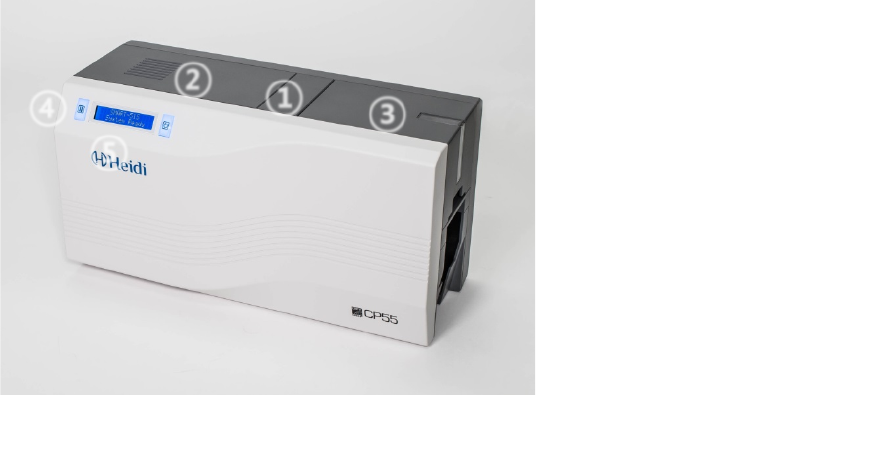
The following shows the outside functional features found on the printer.
Figure 1 CP55 front features
① Top cover open button
②
Fan
③
Input hopper
④
LED buttons
⑤
LCD show the process
status
①
② ③
④
⑤
9
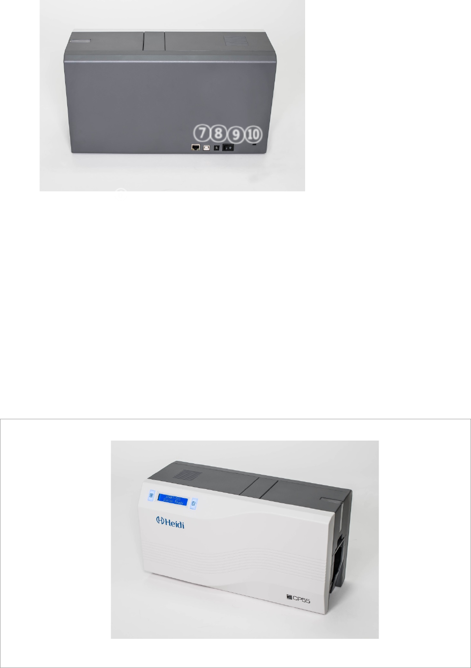
Figure 2 CP55 rear features
There are two models in CP55 card printer series such as CP55, CP55 Dual.
CP55 (Figure.3) is the standard card printer. It can be printed in single side with the encoding.
This manual is prepared based on CP55.
CP55 Dual (Figure.4) has a flipper which can enable to print in both sides. CP55 Dual can print
the both side of the card with the encoding.
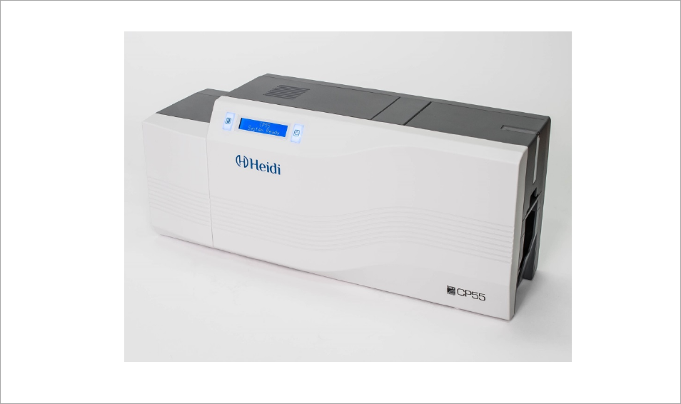
Figure 3 CP55-S (Standard)
⑥ Network port
In case there is no
network option, it is
closed.
⑦
USB port
⑧
24V power connector
⑨
Power switch
⑩
Kensington Lock
⑧
⑨
⑩
⑦
⑥
10
Figure 4 CP55-D (Dual)
11
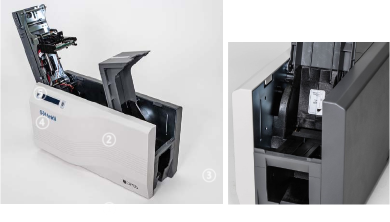
1.2. Printer inside features
In CP55 printer, the ribbon is installed by a ribbon cartridge which can be used semi
permanently. The following shows the inside functional features found on your CP55
printer.
Figure 5 CP55 Inside features
① Output hopper(Stacker)
Collect the printed card and/or encoded cards. Maximum 40 cards are loaded and the
extra printed/encoded card is passed out. It can be withdrawed when pulling forward.
② Input hopper
Load the cards for printing. Maximum 100 cards are loaded when cover is closed;
Maximum 200 cards are loaded when the cover is opened.
③ Card thickness control lever
Adjust the cards thickness.
④ Ribbon cartridge
Install the ribbon and the disposable cleaning roller.
⑤ Thermal Print Head
This enables the cards to be printed.
(Caution!: This is very hot after printing. Do not contact the surface of the Thermal
Print Head with fingers or a sharp metal object to avoid degrading print quality or
damaging printer head permanently.)
①
②
③
④
⑤
12
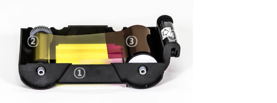
1.3 Ribbon cartridge features
CP55 printer uses the ribbon cartridge as below picture.
Figure 6 Ribbon cartridge features
① Ribbon cartridge
-. Install a ribbon and a disposable cleaning roller provided with the ribbon.
-. This semi-permanent ribbon cartridge is a component of the printer. Printer does
not operate if it is broken or damaged. In this case, please contact printer reseller.
② ③ Take up & Supply parts
-. Ribbon is wrapped to the supply parts as the Picture. It should be installed as the
Figure.6
④ Disposable cleaning roller
-. It removes dust on the surface of card to improve print quality before the card is
printed.
It should be changed together with the ribbon.
-. After installing the disposable cleaning roller to the ribbon cartridge, peel off the
protective film.
-. It is provided with the ribbon.
①
Ribbon cartridge
②
Take up parts
③
Supply parts
④
Disposable
Cleaning Roller
①
② ③ ④
13
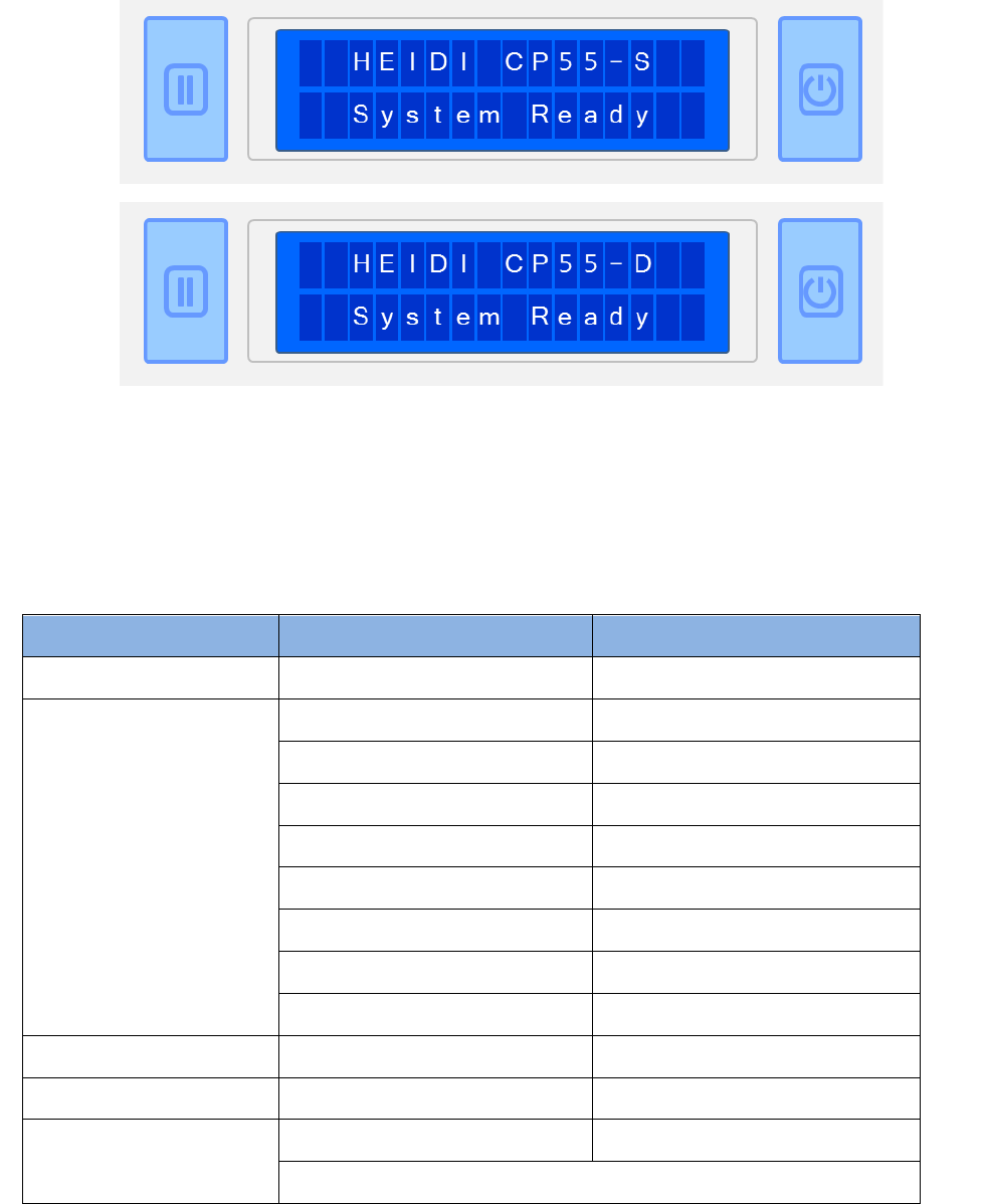
1.4 Display and Buttons
Control panel of Printer consists of 2 lines LCD and 2 buttons. The 2 buttons have the functions
as shown in the Figure 7. The main LCD message of CP55 printer is ‘HEIDI CP55-S’. On the
other hand, CP55 Dual printer is ‘HEIDI CP55-D’.
Figure 7 CP55-S & CP55-D Display and Buttons
The status of CP55 is ‘Initializing’ when boot up. It is changed to ‘System Ready’ if the printer is
fine. It is change to ‘Printing’ when the printer is working. In case of sensing an error, it is
changed to ‘Error’ status. Whenever the top cover is opened, the operation is stopped and the
status is ‘Top Cover Open’.
The functions of the button under each status are as below table.
Status
Left Button
Right Button
Initializing
N/A
N/A
System Ready
Ribbon Type/Balance
Sleep (Hold on 5 sec.)
User Printed Counts
Initializing (when Sleep Mode)
Do Test Print
OK
Network IP Address
Subnet
Gateway
Network MAC Address
Pulling out the card
Printing
N/A
N/A
Error
Retry
Cancel
Top Cover Open
Move to backward a card
Move to forward a card
Cleaning Mode (when both buttons are pushed)
Left
Button
Right
Button
Two Line LCD
14
2. Printer installation
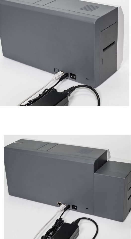
2.1. Connecting a power and a USB cable
Connect the power and USB cable as the below picture. Please refer to the ‘Network
Configuration’ if you use the LAN connection.
Figure 8 CP55 Connection of power and USB cable
Figure 9 CP55 Dual Connection of power and USB cable
15
2.2. Fitting the ribbon
Before printing, prepare the related items such as a card, a ribbon and a cleaning roller.
In this section we invite you to know the proper method of installing the ribbon and the
cleaning roller into the printer.
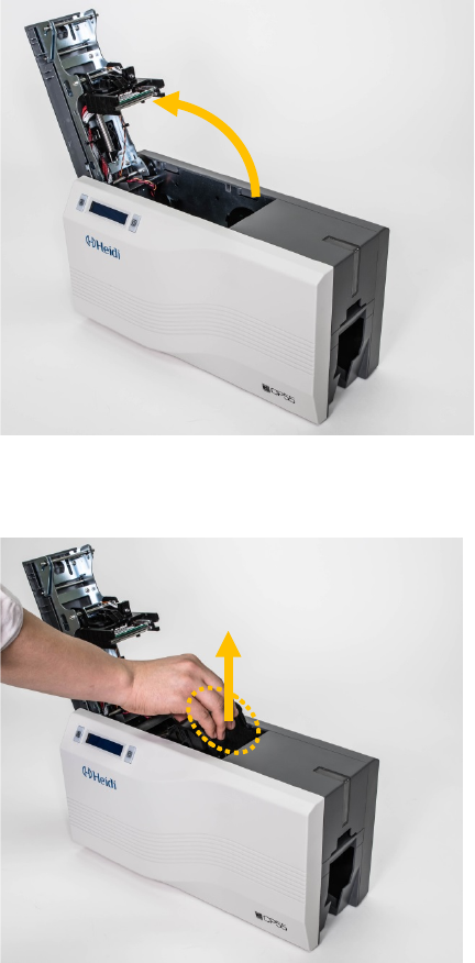
(1) Turn off the printer
(2) Open the printer top cover by
pressing the top cover open button.
Figure 10 Top Cover open
(3) Take out the ribbon cartridge.
Figure 11 Take out the ribbon cartridge
16
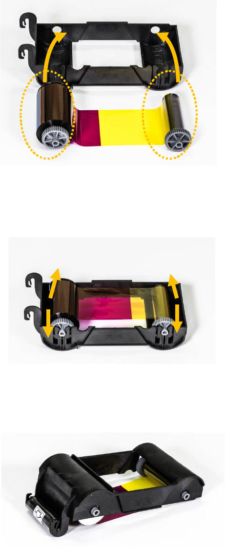
(4) Install a ribbon into the ribbon
cartridge as the right picture.
Figure 12 Loading the ribbon 1
(5) Insert the supply side of the ribbon
to no.1 hole and press the opposite
(no.2). Insert the take-up side of the
ribbon same method to no.3 and no.4.
After inserting, tighten the ribbon.
(Caution! If the ribbon is not tightened, a rolling
up error might be happened.)
Figure 13 Loading the ribbon 2
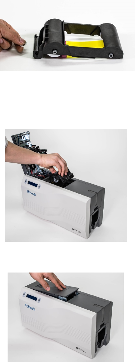
(6) Install the disposable cleaning roller
to the ribbon cartridge.
Figure 14 Installing the cleaning roller
①
②
③
④
17
(7) Peel the protective wrapper from the
cleaning roller.
After removing the protective wrapper, the
cleaning roller should be kept clean from
fingerprints, dust and foreign substances
to avoid contamination because it is
adhesive.
(Caution! Do not use without peeling off
the protective wrapper because the
cleaning roller cannot perform its function.)
Figure 15 Peeling the protective wrapper
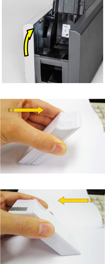
(8) Install the ribbon cartridge into the
printer after installing the ribbon with a
cleaning roller to the cartridge.
Figure 16 Installing the ribbon cartridge
(9) Close the top cover
(If it is not closed properly, check the
installation state of the ribbon cartridge.)
Figure 17 Close Top Cover
18
2.3. Loading the cards
This section shows how to load the plastic cards.
(1) Open the input hopper cover.
Adjust the card thickness with the
card thickness control lever.
(Caution! If the adjustment is not correct, it
will make some error. Use the type of
cards in the specification of this manual.
Always keep the card surface clean state.)
Figure 18 Adjusting the card thickness lever
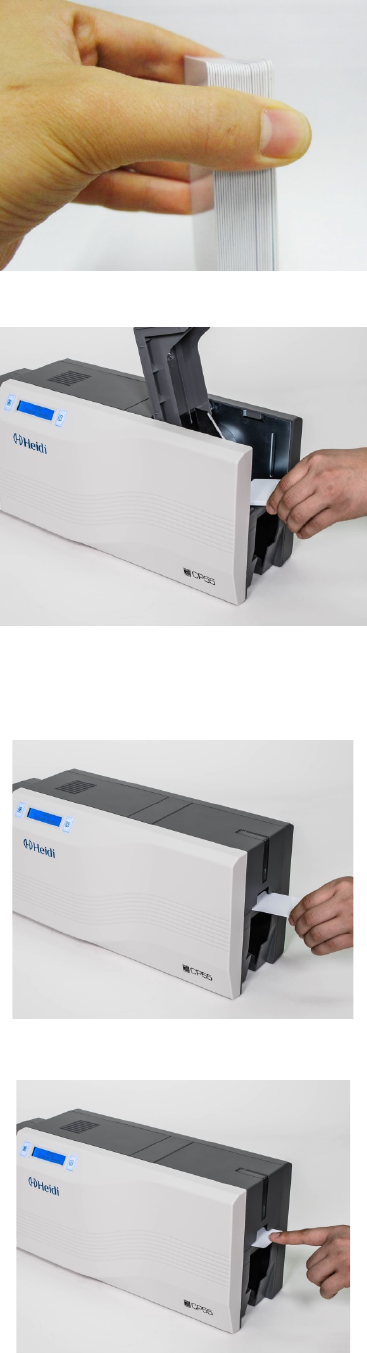
(2) To separate cards from each
other, push a stack of cards back
and forth to an angle about 45
degrees vertically.
(Static charge makes cards stuck with
significant adhesive force. These cards
must be physically separated from each
other before inserted into the feeder. If not
separated, feeding or printing problems
may occur.)
Figure 19 Preparing the card 1
Figure 20 Preparing the card 2
19
(3) Stand the stack of cards
vertically after separating
Figure 21 Loading the cards 1
(4) Load the cards on the input
hopper properly and close the
hopper cover.
Figure 22 Loading the cards 2
(5) When insert each one card,
insert the card to the end as left
picture
(Caution! If the printer has a lock device,
a card can’t be inserted one by one.
You can select the ‘lock device’ option
when you order the printer. It can lock
the top cover and hopper to prevent
extracting the ribbon and cards without
key.)
Figure 23 Loading the cards 3
Figure 24 Loading the cards 4
20
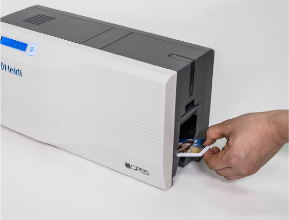
2.4. The withdrawal of printed cards.
Printed cards are passed out to the stacker of front bottom side of CP55 printer.
Figure 25 CP55 Withdrawal a card
CP55’s stacker can be divided as following image. so you can withdraw the printed cards
easily.
21
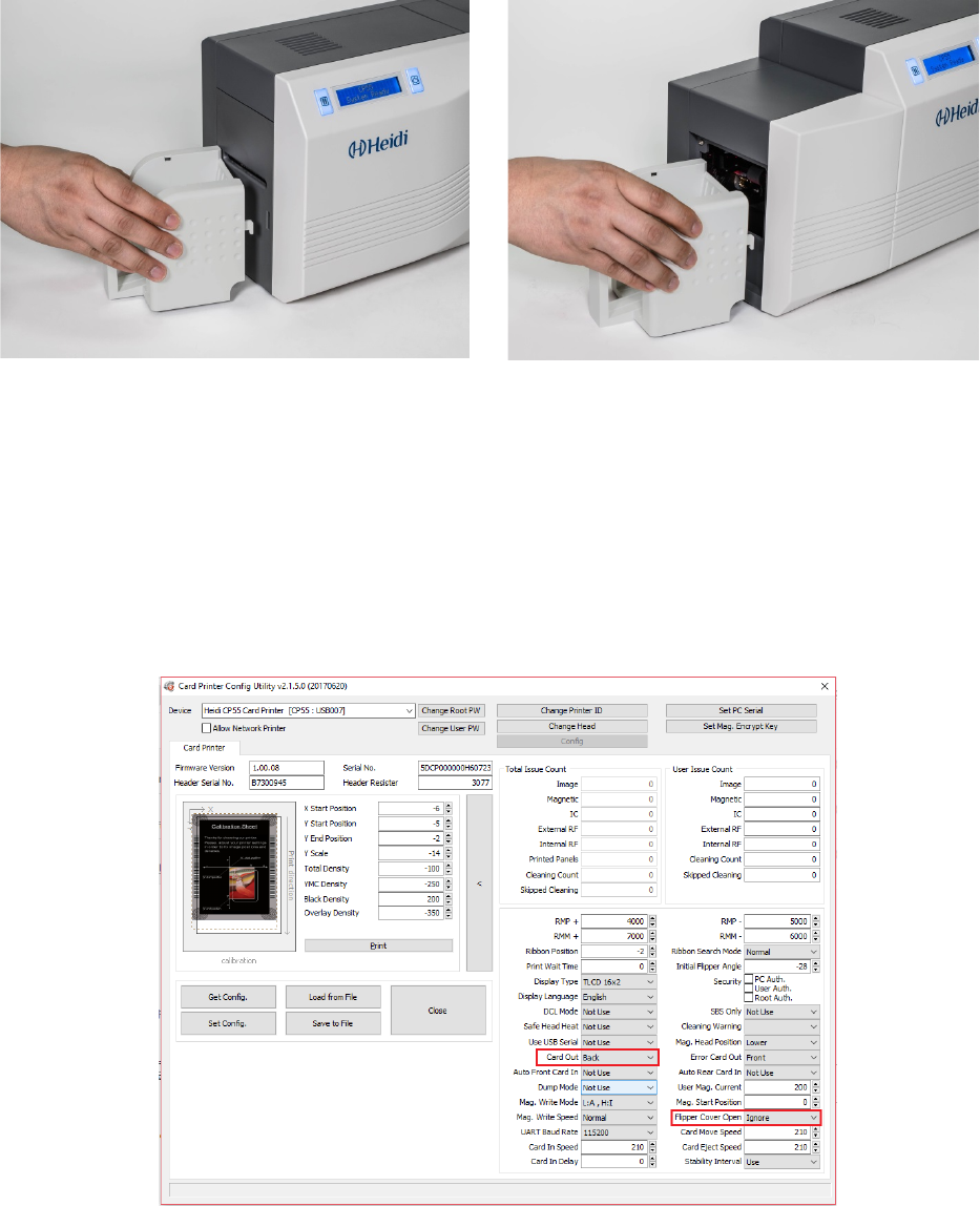
2.5. Rear Stacker (Option)
CP55 can install a rear stacker for option at the back of the printer. In case of CP55, please
install into the slots at the backside. In case of CP55 Dual, please open the back cover of
the printer and install it.
Figure 26 CP55 installation of Rear Stacker
Figure 27 CP55 Dual installation of Rear Stacker
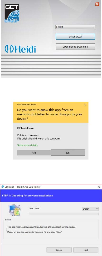
After that, set the value of ‘Card Out’ to ‘Back’ in the Configuration Program.
In case of CP55 Dual, set the value of ‘Flipper Cover Open’ to ‘Ignore’ in the Configuration
Program
Figure 28
Setting values in the Configuration program
22
2.6. Driver installation (Windows 7 / 8 / 10)
(1) Please insert the installation CD.
Please choose language and click
“Driver Install”.
Figure 29 Install printer driver 1
(2) When “User Account Control”
window is opened, click “Yes”
Figure 30 Install printer driver 2
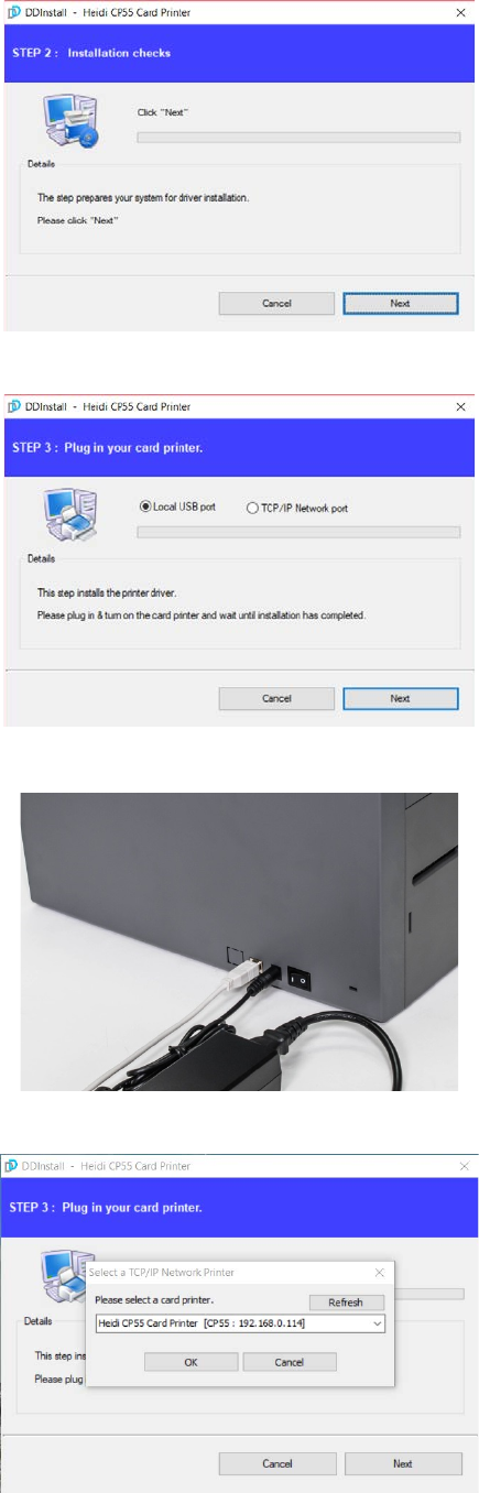
(3) STEP 1:
Please turn off printer if it is
connected to PC. Please click
“Next”.
When you click “Next”, older driver
will be removed automatically.
This process will take several minutes to remove
older driver.
You can select the languages by selecting the
combo box as shown on the left picture.
Figure 31 Install printer driver 3
23
(4) STEP 2:
When you click “Next”, the driver
installation will be ready.
Figure 32 Install printer driver 4
(5) STEP 3: - USB
Please click “Next” if printer is
connected to USB only.
If you want to install the driver for a
printer connected to network, please
select the “TCP/IP Network port” and
select the proper printer as step (7).
Figure 33 Install printer driver 5
(6) Please turn on the printer
(Network cable is not supplied. Please
ask network administrator for more
questions.)
Figure 34 Install printer driver 6
(7) STEP 3: - Network
Please select the printer that you want
to install in the list and click “OK”.
(If no printer comes out on the window,
please check the connection.)
Figure 35 Install printer driver 7
24
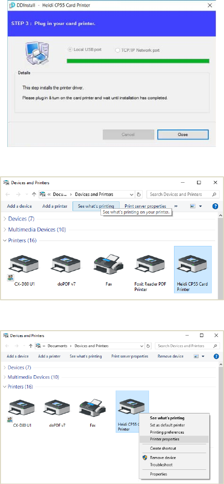
(8) When driver installation is
completed, please click “Close”
Figure 36 Install printer driver 8
(9) Please open “Devices and
Printers” from “Hardware and
Sound”. Please check if “Heidi CP55
Card Printer” is created.
Figure 37 Install printer driver 9
(10) Please click the right mouse
button after cursor is placed on
“Heidi CP55
Card Printer” icon. Click
“Printer properties”.
Figure 38 Install printer driver 10
25
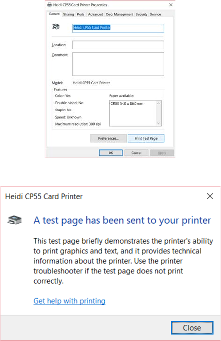
(11) Please select “general” tab and
click “Print test page” in “Heidi
CP55 Card Printer Properties”
window.
Figure 39 Install printer driver 11
(12) Please check test card if it is
printed properly and click “Close” if
a card is printed properly.
(If card is not printed or error comes out,
please refer to “Trouble Shooting”.)
Figure 40 Install printer driver 12
26
3. Driver configuration
3.1. Printer Properties
To check printer properties, you need to open printer driver. Please open
“Devices and Printers” and right-click “Heidi CP55 Card Printer”.
Click “Printer Properties”.
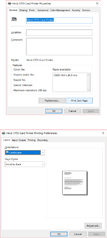
(1) Printing Preferences
Please click “Preferences…” shown on the
bottom of the left picture.
Figure 41 Printer properties
(2) Layout
- You can select either horizontal or
vertical printing direction. To apply your
selection, click “OK”.
Figure 42 Layout
27
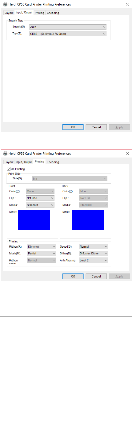
(3) Input / Output
[ Supply Tray ]
Supply : You can select “Auto” if CP55
has 1 input hopper. Please select the
hopper if it has a multi hopper.
Tray : You can select “CR-80” because
CP55 supports CR80 cards only.
Figure 43 Input / Output
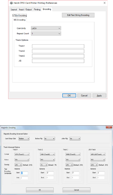
(4) Printing
Do Printing : You can select printing or
not
[ Print Side ]
Side : Please select one side printing or
both sides printing (It is possible only when
you have a flipper.)
[ Front / Back ]
Color : You can select color or mono
print.
Flip : You can flip an image
Media / Mask : You can indicate the area
to print by using a
predefined mask or user
defined mask (white card, smartcard,
Magnetic stripe card, etc.) on front or back
side.
[ Printing ]
Ribbon : It shows the type of installed
ribbon. You don’t need to select this option
as CP55 recognizes ribbon automatically
with RF Tag.
Speed : Set printing speed and quality
Mode : Set printing mode
Standard : Default print mode. Prints all
area of printing
Figure 44 Printing
You can define a mask.
User defined mask uses BITMAP file
(1012 X 636 pixels).
Blue (RGB(0,0,255)): Print and
Overlay
Sky Blue (RGB(0,255,255)): Overlay
only
Pink (RGB(255,0,255)): Print only
Yellow (RGB(255,255,0)): Florescent
28
Partial : Partial print mode. It is printed
partially for the print area only. Printing
speed can be faster than standard mode.
Dither : There are 3 possible selections,
Threshold, Random, and Diffusion Dither.
It is performed with K and KO ribbon only.
(Please select “Diffusion Dither” for high
quality.)
Ribbon Save : Select the split function or
not when K ribbon is installed
K ribbon Split : You can set the both
sides (Front:YMCO, Back:K) to save color
ribbon(YMCKO, HYMCKO, BYMCKO). It is
only activated while printing both sides
option is set.
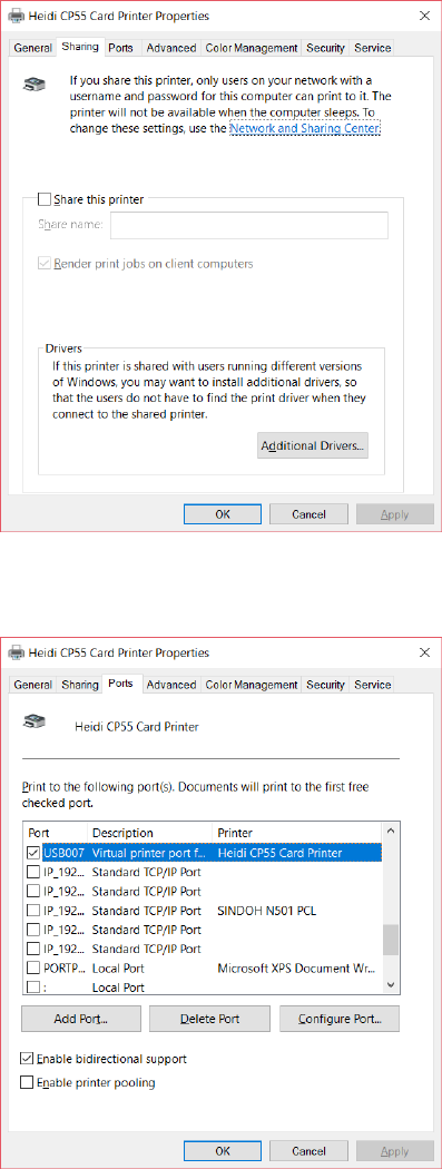
(5) Encoding
This tap will be shown only when
Magnetic encoder is installed.
Do Encoding :
You can select encoding or
not
Coercivity : You can select the coercivity
to encode
Loco : 300, 600 Oe.
HiCo : 2760 Oe.
SpCo : 4000 Oe.
Auto : Defined automatically
Repeat Count : You can select the retry
count to encoding when encoding is
failed
Figure 45 Encoding
(7) Encoding Advanced Option
Card Stripe Side : The location of
magnetic stripe [Bottom / Top]
Before Flip : Do flipping before encoding
[No / Yes]
After Flip :
Do flipping after encoding [No /
Yes]
Track Advanced Options :
Format : Encoding format (IATA, ABA,
MINS, JISII, Bits Mode)
Figure 46
Magnetic Encoding Advanced Option
29
Track 1 : (default) IATA
Track 2 : (default) ABA
Track 3 : (default) MINS
JIS II Track : (default) JIS II
Density: MS encoding density (210, 75)
Text Encoding Sentinels : Start, End
Marker for text magnetic encoding
Start : Start Marker
End : End Marker
30
3.2. Advanced Options
To change the detailed configuration, In the ‘Layout’ tab shown, Please click
“Advanced…” shown on the bottom of the ‘Layout’ tab of the ‘Preferences’.
Reset Default Values: Reset to default.
Color Correction: You can correct gamma for colors. You need to use
CardPrinterConfig to adjust color densities.
- Main [-100:100] : Correct gamma for all panels
- Yellow [-100:100] : Correct gamma for yellow panel
- Magenta [-100:100] : Correct gamma for magenta panel
- Cyan [-100:100] : Correct gamma for cyan panel
- Black [-100:100] : Correct gamma for black panel
- Overlay [-100:100] : Correct gamma for overlay panel
Position Processing: Set criteria for resin black processing.
- Color [-32:32]: to set the position of color panels
- Mono [-32:32]: to set the position of resin or mono panel
- Overlay [-32:32]: to set the position of overlay panel
Resin Black(K) Processing: Set criteria for resin black processing.
- Text [0:100]: to set density criteria for extracting black objects
- Dot [0:100]: to set density criteria for extracting black dots
- Threshold [0:100]: to set density criteria on dithering
- Dithering Degree [0:100]: to set sharpness on dithering
- Resin Extraction: You can set the method to extract resin black when you use
design programs. It will be set automatically.
31
Black Object: to extract resin black automatically for text, line, box,
circle, binary images, etc.
Black Text: to extract resin black for text only
Black Dots: to extract resin black for all of black
Black Dots only: to extract resin black for all of black and not to print on
color panels
Not Use: not to extract resin black
Extra Controls : Other options
- Fast Alignment [On/Off]: to set the position of input card to the magnetic
encoder or normal printing. If it is on, the printer can save the time to encode
- Rewritable Erase Density [0:100] : to set Erase Density on Rewritable printer
Wait Option:
- Wait at Internal Module Contactless Encoding Position [On/Off]: to set
whether to wait at the Internal RF encoder or not
Card Side [Front/Back]: to set the direction of card when waiting
Wait Position [-100:100]: to set the position of card to wait from the
criteria position. Unit is 0.1mm
Wait Time [0:1000]: to set time to wait. Unit is second
- Wait at External Module Contactless Encoding Position [On/Off]: to set
whether to wait at the External RF encoder or not
Card Side [Front/Back]: to set the direction of card when waiting
Wait Position [-100:100]: to set the position of card to wait from the
criteria position. Unit is 0.1mm
Wait Time [0:1000]: to set time to wait. Unit is second
- Wait at Internal Module Contact Encoding Position [On/Off]: to set whether to
wait at the Internal IC encoder or not
Card Side [Front/Back]: to set the direction of card when waiting
32
Wait Position [-100:100]: to set the position of card to wait from the
criteria position. Unit is 0.1mm
Wait Time [0:1000]: to set time to wait. Unit is second
33
3.3. Other settings
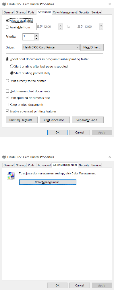
(1) Sharing
You can share a printer with Sharing tab
via Network.
Default is unchecked “Share this printer”.
Figure 47 Printer sharing
(2) Ports
Port tab shows which port is connected
with CP55. CP55 has connection with USB
Virtual printer port as left picture because
CP55 uses USB connected to PC.
(Caution! This port is selected
automatically. It is recommended to
maintain default.)
Figure 48 Ports
34
(3) Advanced
It is available for Working Time setting,
Priority order, Spool print etc. in
“Advanced” tab. “Advanced” setting follows
MS Windows standard. If you want to
change the setting, please refer to the
Window manual.
(It is recommended to maintain default.)
Figure 49 Advanced
(4) Color Management
In “Color management” tab, you can select
color management profile fit to the printer.
CP55 uses color profile to express optimal
color. The driver selects color profile
automatically to fit each ribbon.
(It is recommended to maintain default.)
Figure 50 Color Management
35
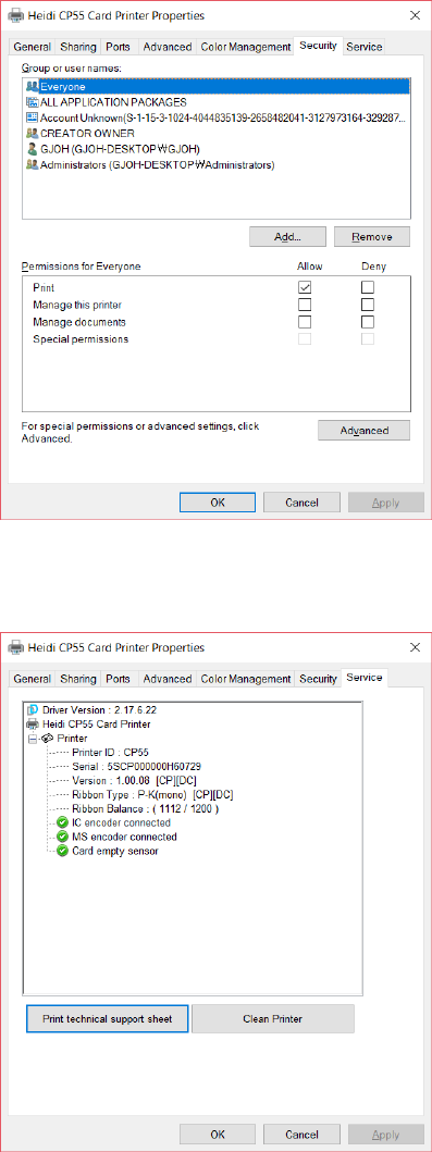
(5) Security
You can set the permission to use a printer.
Depend on the permission, the certain
group or user can print, manage the
printer/documents or not.
Figure 51 Security
(6) Service
You can recognize the modules to connect,
printer serial, printer ID, driver version,
firmware version, type of ribbon & balance
and printer’s status.
You can print the “technical support sheet”
on a card to check printer’s setup value.
To clean printer, please insert a cleaning
card in a hopper and click “Clean Printer”.
For further details, please refer to “4.2.
Cleaning Printer”.
Figure 52 Service
36
4. Utilities
4.1. Card Printer Config
CP55 is produced with optimized setting. You need to adjust setting value if required or
spare parts are replaced using CardPrinterConfig in our Installation CD.
You can adjust following settings with CardPrinterConfig.
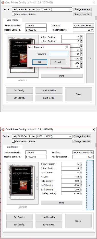
(1) Run CardPrinterConfig
Password input window is displayed when
you run this program. If you input the
correct password, the recorded setup value
will be shown and you can change values.
The password is saved to CP55 printer. So
if you use another PC with same printer,
previous password is required to run this
program. (Default password is none.
Please press OK if you have not set
password.)
Figure 53 CardPrinterConfig Log-in
When you are successful to log-in, you can
set values shown as left picture.
Figure 54 CardPrinterConfig start
37
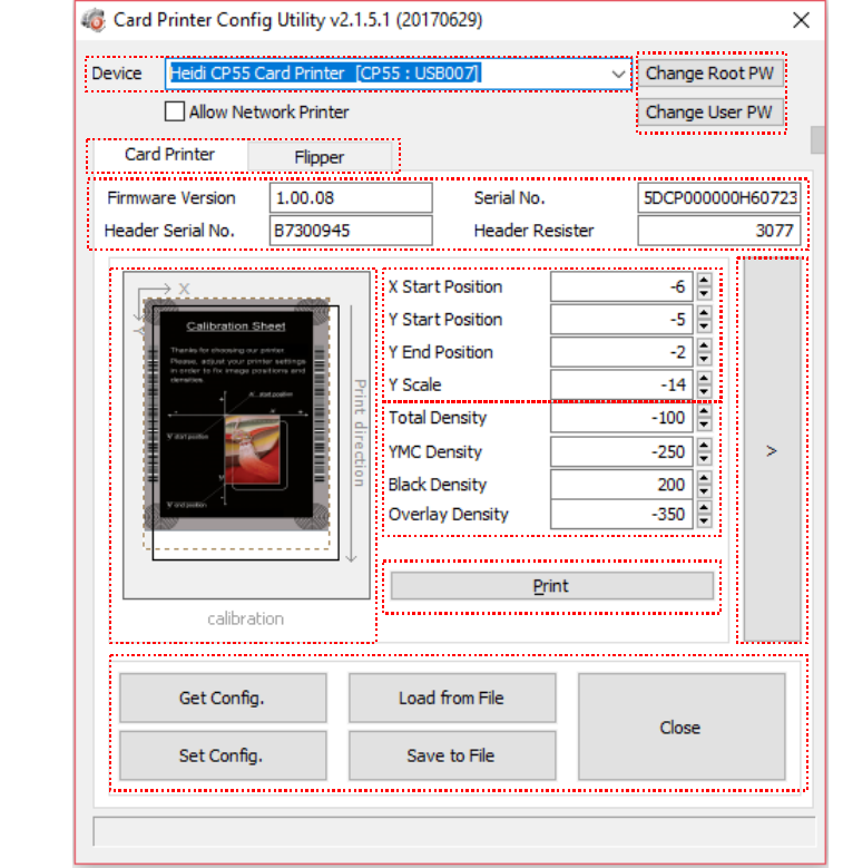
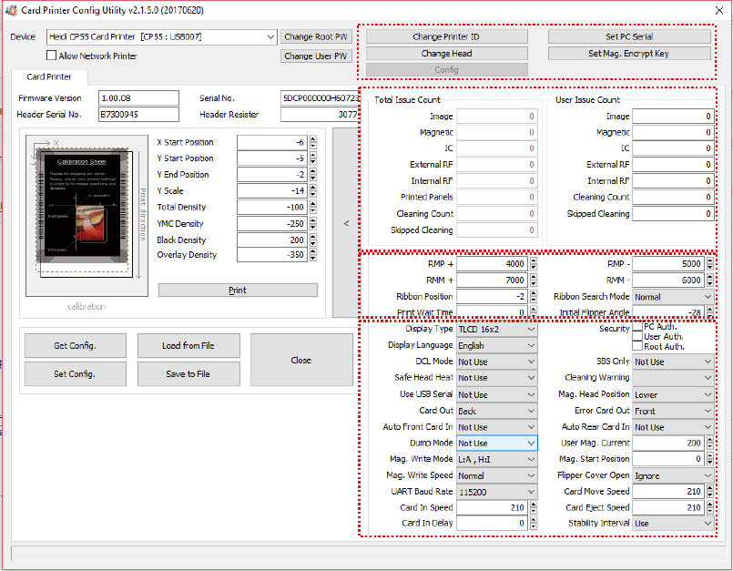
(2) Card Printer Basic Setup
Figure 55 CardPrinterConfig – Card Printer Basic Setup
① To show connected printers
Device: You can select a printer using pull-down menu. “HEIDI CP55 Card Printer”
is a name of printer. “CP55” is printer ID, “USB005” is connected port. If you
connect the Network printer, please check the “Allow Network Printer” and select
in the pull-down menu.
② To set administrator password and user password.
Change Root PW: To set administrator (root) password. This password is used to
verify user authority for CardPrinterConfig and User Authentication. Also it is
required for User password management. (Please set password for security use.)
Change User PW: To set user password for User Authentication.
①
②
③
④
⑤
⑥
⑦
⑧
⑨
⑩
38
③ Click “Card Printer” tab.(If flipper is installed, you can setup flipper setting value by
“Flipper” tab..
④ To show firmware version, serial number of printer and serial number, resister &
type of print head.
⑤ To show print area. It shows exaggeratingly for user convenience.
⑥ To set print area. Please set it properly to print on an entire card because CP55 is
a direct thermal card printer. When you click “⑦ Print”, a card is printed as like “④
example”. Please set values properly that all circles of each corner are printed and
blank spaces are 0.4mm ~ 0.5mm in the top and the bottom of a card. Please set
values by following order.
X Start Position: Please set right and left properly by adjusting X position.
Y Start Position: Please set the start position of printed example image and
blank space in the top is 0.4mm ~ 0.5mm.
Y End Position: Please set the end position of printed example image and blank
space in the bottom is 0.4mm ~ 0.5mm. It is recommended to set bigger
value for “Y scale” than default.
Y Scale: Please set to show circles in the bottom.
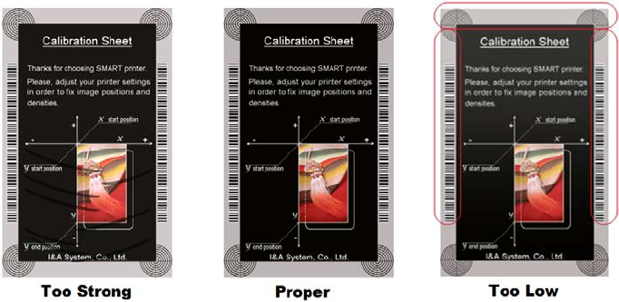
⑦ To set density. CP55 enables to set different density for each color, resin black
and overlay. So, please set each density for high quality. Please optimize the
quality by adjusting each value. To optimize, you repeatedly adjust the density and
print a Calibration card and check the print state until you get the optimum.
Total Density: To set all of the density (Color, Black and Overlay) at one time.
YMC Density: To set color density. Please maximize YMC density as you can,
which enables to express range of color and vivid images. If it is too strong, green
or red marks are appeared. If it is too weak, the print quality will be dull.
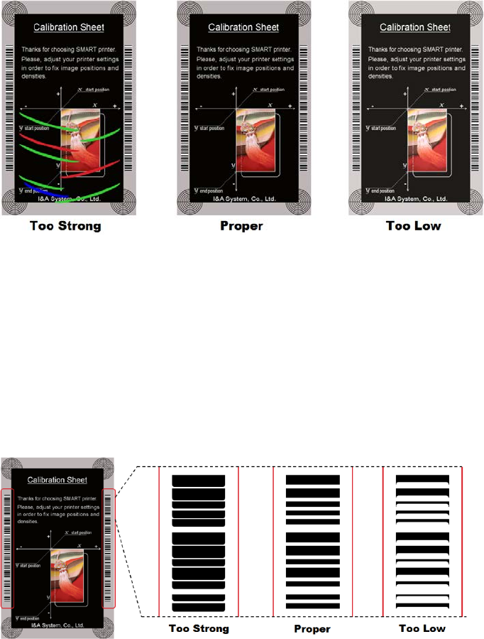
39
Figure 56 Color density
Black Density: To set resin black density. In the picture, barcode is printed to
express density.
When density is too strong, barcode is printed too thick. When density is too weak,
barcode is too thin. Please adjust resin black density to express clear barcode.
Please refer to the following pictures.
Figure 57 Resin Black density
Overlay Density: To set overlay density. Please set it when overlay is printed on
surface regularly. If it is too strong, it is hazy and marks are appeared. If it is too
weak, overlay panel is not printed edge areas. You can check it with printed card
under the light.
40
Figure 58 Overlay density
⑧ To print calibration card.
⑨ To show advanced Setup.
(It is recommended not to set advanced setup.)
⑩ To load or save values.
Get Config.: to get values from current printer
Set Config. : to set values to current printer
Load from File: to load values from file
Save to File : to save values to file
Load Default : to load default. Please adjust values again after load default.
Close : to close CardPrinterConfig
41
(3) Card Printer Advanced Setup
You can set more values.
Figure 59 CardPrinterConfig – Card Printer Advanced Setup
① You can set Printer ID, PC serial, Print head and Magnetic encryption key.
Change Printer ID: When CP55 is used by SDK, you can set unique ID for CP55
printer regardless of whether it is connected by USB or what IP address is. It is useful
to connect and use several printers. Default is “CP55”.
Set PC Serial: One of security function. You can use a printer with specific PC.
It is activated when you click “Set PC Serial” after “PC Auth.” of ④ is checked and
rebooted. At that time, the specific information of used PC is saved to CP55 printer.
Change Head: When you replace thermal print head, you must change head
information for optimal quality. Please change head serial number, resistor and type of
head in the Change Head Dialog window after click “Change Head”.
①
②
③
④
42
Set Mag. Encrypt Key: One of security function. When you use SDK, you can encrypt
magnetic stripe encoding data transmitted by USB. You can define and save the
encryption key to CP55 using “Set Mag. Encrypt Key”.
② To show how many cards are issued with CP55 printer. “Total Issue Count” is the
number of issued cards from factory shipment, “User Issue Count” is the number of
issued cards from replacing head. When you replace a head, please initialize the
number by ticking “Reset User Issue Count”.
③ To show ribbon motor management. CP55 recognizes ribbon color automatically and
controls motor by ribbon remaining. “RMP+”, “RMP-“, “RMM+”, “RMM-“ are necessary
variables to control ribbon motor. Please do not change values for them as it affects
card quality.
RMP+: Set the ribbon motor’s max torque value while printing when the balance is
max.
RMP- : Set the ribbon motor’s min torque value while printing when the balance is min.
RMM+: Set the ribbon motor’s max torque value while moving when the balance is
max.
RMM- : Set the ribbon motor’s min torque value while moving when the balance is min.
Ribbon Position: Set the ribbon arrangement position
Ribbon Search Mode: Set the ribbon Search method
Print Wait Time: Set the time from lifting down the print head to starting print
Initial Flipper Angle: Set the angle of flipper when card is out if the ‘Card Out’ is
‘Back’
④ Please refer as below for other values.
Display Type: Set a type of LCD display module
UART Baud Rate: Set the speed of communication of Internal Serial port. It is used for
the KIOSK model.
Security: There are several ways to set a security function for CP55.
PC Auth.: You can use a printer with specific PC. It is activated when you click “Set
PC Serial”.
User/Root Auth.: You can set passwords for User and Administrator.
DCL Mode: When you use SDK and print cards with DCL mode, you don’t need to
install printer device driver.
43
SBS Only: Please enable it when you issue cards with software programed by SDK.
This option disables printer device driver.
Safe Head Heat: Set not to print if the print head is overheated.
Cleaning Warning: Set to show the ‘Do cleaning’ message periodically
Use USB Serial: When CP55 is connected to USB, it transmits the USB serial number
to PC. Default is the same number used by all CP55. Please set this option when you
use multiple CP55 printers connected to 1 PC via USB. It enables unique serial
numbers for each USB.
Mag. Head Position: CP55 can install the magnetic encoder on lower side of a card.
Card Out: Set the way to eject cards.
Error Card Out: Set the way to eject error cards.
Auto Front Card In: Set to input a card automatically if the front card-in sensor
detects a card. It is used for the KIOSK model.
Auto Rear Card In: Set to input a card automatically if the rear card-in sensor detects
a card. It is used for the KIOSK model.
Dump Mode: It records log data to inspect the operation of printer.
User Mag. Current: The default current value when the user selects to use the
defined value when magnetic encoding
Mag. Write Mode: You can order the way how to encode magnetic stripe.
“L:A, H:I”: encodes 3 tracks at once for LoCo card and encodes at twice by dividing 1,3
and 2 track for HiCo card.
Magnetic Start Position: Set the start position of magnetic stripe when you encode.
Mag. Write Speed: You can order the speed to encode magnetic stripe.
Flipper Cover Open: Set to notify the Flipper cover is opened or not. [Check / Ignore]
UART Baud Rate: To set the communication speed (Baud rate) of the external device
connected to Printer by serial.
Card In Speed: set the speed of inputting a card
Card Move Speed: set the speed of moving a card
Card Eject Speed: set the speed of ejecting a card
Card In Delay: set the delay time to operate the hopper motor.
Stability Interval: select stability or faster speed. Default is ‘on’, stability.
44
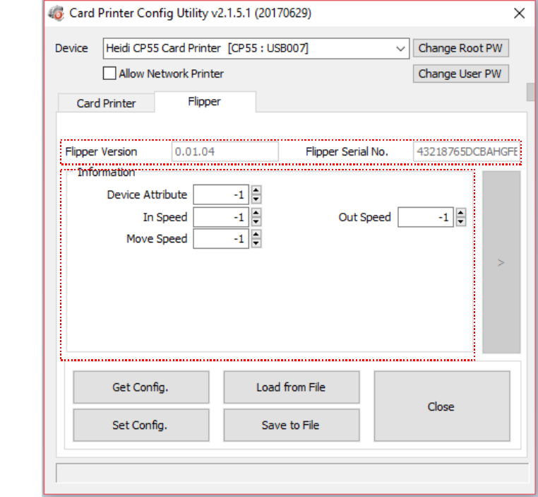
(4) Flipper Setup
This ‘Flipper’ tab is shown when the flipper option is installed.
Figure 60 CardPrinterConfig – Flipper Setup
① To show installed flipper
Firmware version and serial number of flipper
② To set configuration of flipper
Device Attribute: Basic attribute of flipper
Card In Speed: Set the speed of inputting a card into a flipper
Cade Move Speed: Set the speed of moving a card in the flipper
Card Eject Speed: Set the speed of ejecting a card from the flipper
①
②
45
4.2. Network configuration
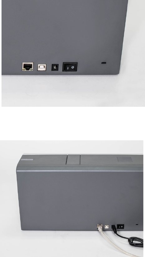
(1) Connecting network port
The printer which installed with
network option has a port for
network connection as shown in the
left picture.
①
Network Port
②
USB port
③
Power Supply Connector
④ Power Switch
Figure 61 Rear view of CP55 printer 1
Please connect network cable
(RJ45) to a printer.
(Network cable is not supplied. Please ask
network administrator for more questions.)
Figure 62 Rear view of CP55 printer 2
Please run NetAdmin.exe in the CP55 installation CD to set or change network configuration.
① ② ③ ④
46
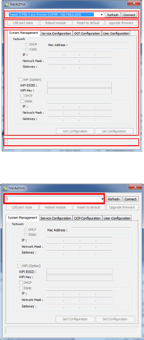
(2) Network configuration
NetAdmin is run as the Pic.72 after
turning on CP55 network printer.
① Printer Connection Status
Searches local network, finds and
shows available network printer.
② Network Module Management
Searches connected encoder on
network module. Reboots, Resets
network module. Firmware upgrade
available
③ Printer Configuration
Sets detailed system configuration.
④ Network Information
Shows firmware version of network
module
Figure 63 Running the NetAdmin
When no printer is connected to
network, there is no printer shown
on the box.
Please click “Refresh”.
If no printer shown, please check as
below,
1. Please check the printer is turned on.
2. Please check network cable is
connected to network hub and works
properly (LED lamp blinking).
3. Please check if there is DHCP server
in the local network. When DHCP
server is not in your local network,
you need to set Static IP.
4. If Static IP is used, please check the
IP configuration. If another device
uses same IP address, it doesn't
work.
Figure 64 Network printer is not found
③
④
②
①
47
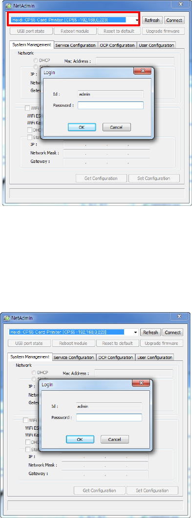
If you are unable to find printer in
local network, please connect
printer
by USB. You can setup network by
USB.
When you click Refresh, you can find a
printer connected by USB as shown in the
left picture..
You don’t need to install device driver
for network configuration by USB.
Please ignore messages related to
device installation.
You can change values of “System
Management” only when you connect a
printer by USB. Please connect a printer
by network to use all of the functions of
Netadmin.exe.
Figure 65 Connecting to USB port
Please select a proper printer and
click “connect”. Please enter
password and click “OK”.
Default password is “admin”.
Figure 66 NetAdmin Log-in
48
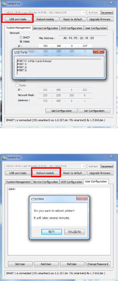
“USB port state” shows USB device
status connected on network
module.
Network module has 4 USB ports.
Network module supports PC/SC.
When you install the encoders that
support PC/SC on network module, you
can recognize the status of encoders.
Figure 67 USB port state
“Reboot module” reboots network
module.
Please click “Yes” when pop-
up window
comes out for reboot.
It takes 1 minute to reboot.
Please click “Refresh” after reboot.
When proper printer shown, please
connect printer by clicking “Connect”.
Figure 68 Rebooting the network module
49
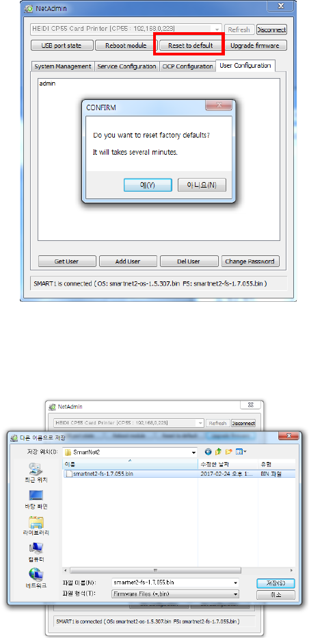
“Reset to default” resets to default
and reboot network module.
Please click “Yes” when pop-up window
comes out for reset.
It takes 1 minute to reboot.
Please click “Refresh” after reboot.
When proper printer shown, please
connect printer by clicking “Connect”.
Figure 69 Reset to default
“Upgrade firmware” enables to
upgrade firmware of network
module.
You can choose a firmware file.
Figure 70 Upgrading the firmware 1
50
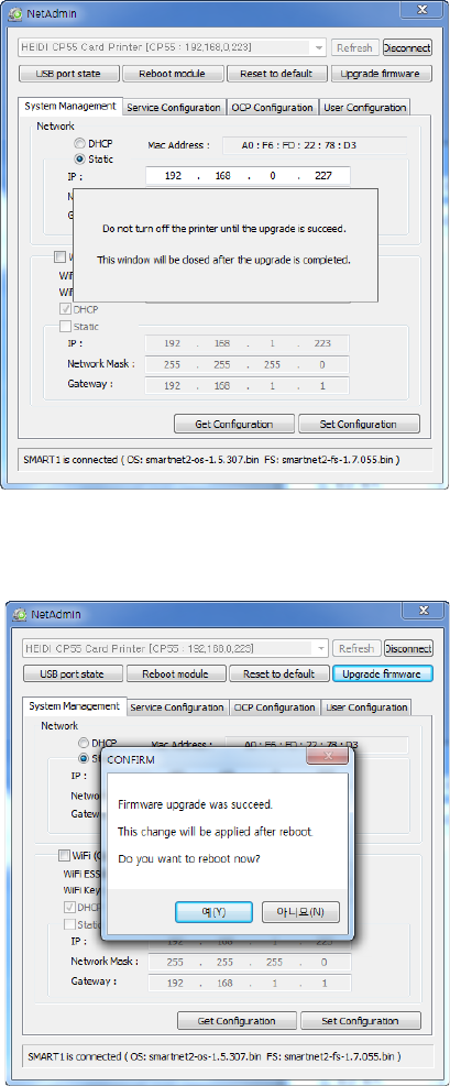
Warning box will be shown during
firmware upgrade for network module.
It is recommended not to do other work
during firmware upgrade for system
reliability.
Please do not turn off a printer until the
upgrade is completed.
Figure 71 Upgrading the firmware 2
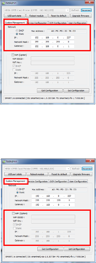
When firmware upgrade is completed,
pop-up comes out for reboot. Please
click “Yes”.
It takes 1 minute to reboot.
Please click “Refresh” after reboot.
When proper printer shown, please
connect printer by clicking “Connect”.
Figure 72 Upgrading the firmware 3
51
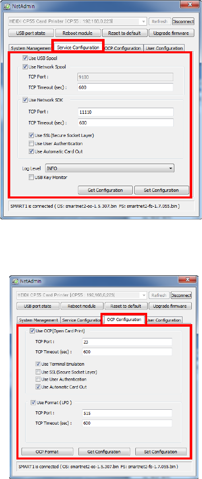
If you setup network automatically,
please choose DHCP.
Please select DHCP or Static.
“DHCP” is default for CP55 printer.
Please enter values for “IP”, “Network
Mask”, and “Gateway”. Click “Set
Configuration”.
Static IP is recommended. DHCP server
assigns IP address automatically but
this IP address is temporary, so the IP
address may be changed. In this case,
the network error may occur in
connecting to CP55 network printer.
If you are not aware of static IP, please
ask network administrator for Static IP.
We recommend using Static IP because
it is more stable for using CP55 network
printer.
Figure 73 Dynamic IP configuration
Wireless Network Configuration
For wireless network, the WIFI option
should be installed in the Network
Module
Check “WiFi (Option)” button to activate
it
Enter the ESSID value in “WiFi ESSID”
to access
Enter the Key value in “WiFi Key”
Set the IP address as the same way of
LAN network
Click “Set Configuration” to save the
configuration value and reboot the
printer
Figure 74 Static IP configuration
52
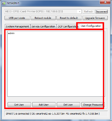
You can change Service
Configuration.
CP55 network printer provides 3 kinds
of service (change “USB Spool”,
“Network Spool” and “Network SDK”).
You can select and change the service
according to the need.
In “Network SDK”, you can control the
printer and print a card well, and the
printer supports SSL (Secure Sockets
Layer) and User Authentication for
security.
Please use default and ask technician
for details.
Figure 75 Network service configuration
You can use Open Card Print
function.
This
function is for send commands and
print through network card regardless of
OS
Click check box “Use OCP”
“Use Terminal Emulation” is value for
getting echo according to the
commands through terminal. For
security, it supports SSL and User
Authentication.
Please do not change default value
except special case..
Figure 76 OCP configuration
53
You can add, change, delete User
and change its password.
“admin” is administrator and you can’t
delete this account. Please don’t forget
password for “admin”
“Get User”: shows available users
“Add User”: makes new user
“Del User”: deletes selected user
“Change Password”: changes password
Figure 77 Network user configuration
54
5. Optional device driver installation
In CP55 printer, you can install the optional devices that encode contact smartcard or
contactless smartcard. If your purchased CP55 printer has optional devices, you should
also install the smart card reader drivers.
5.1. Contact smartcard reader
In CP55 printer, you can install the two types of optional devices which are contact
smartcard reader and mobile SIM smartcard reader. If you have one or more
smartcard reader devices on your printer, you should install the smartcard device
driver as in the following, and connect CP55 printer to your PC.
(1) Run the smartcard driver installer
Insert the smartcard installation CD and find “\Options\Gemalto PC Twin” directory
on your CD. Find the right directory which is installed OS version on your PC, and
run the installer. You can see the smartcard reader driver installation window as the
Figure 51. And click “Next”.
Figure 78 Contact smartcard reader driver installation
55
(2) License agreement
The license agreement window is shown. Check at the agreement and click “Next”.
Figure 79 License agreement
(3) Installation
The installation message is shown as the picture. Click “Install” to install driver.
Figure 80 Installing the contact smartcard reader driver
56
(4) Complete installation
When the installation is completed, the window is shown. Click the “Finish” to
complete the installation steps.
Figure 81 Completing the smartcard reader driver installation
57
5.2. Contactless smartcard reader
In CP55 printer, you can install the two types of smartcard reader which are internal
contactless smartcard reader and external contactless smartcard reader. If you have
one or more contactless smartcard reader devices on your printer, you should install
the contactless smartcard device driver as in the following, and connect CP55 printer
to your PC.
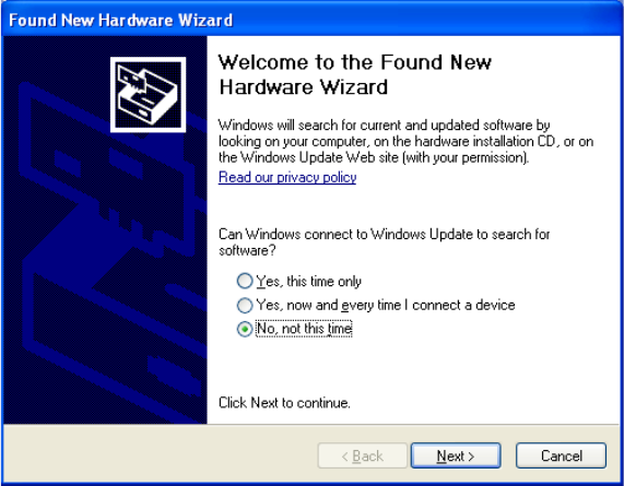
(1) Connect CP55 printer to PC
When you connect the printer to PC and turn on the printer, you can see the “Found
New Hardware Wizard” as the picture, then Check “No, not that time” and Click
“Next” to continue.
Figure 82 Found New Hardware Wizard
58
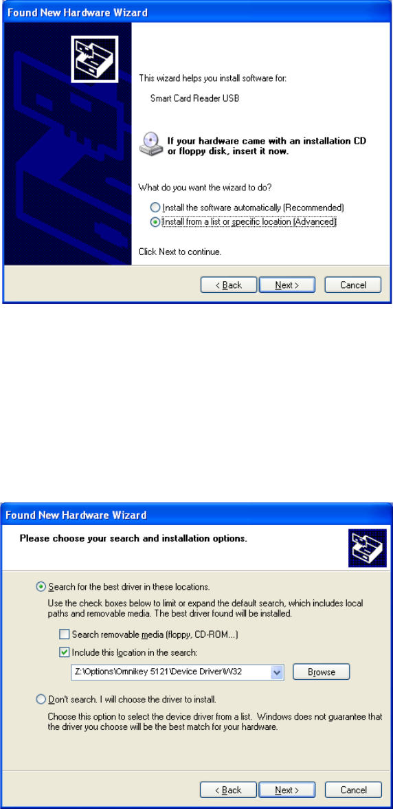
(2) Choose the installation method
At the window as the picture, select “Install from a list or specific location” and click
“Next”.
Figure 83 Installation method selection
(3) Driver location
Insert the smartcard installation CD and find “\Options\ Omnikey 5121” directory on
your CD. Find the right directory which is installed OS version on your PC, and
select the directory as the picture, and click “Next”.
Figure 84 Driver location
59
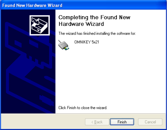
(4) Complete installation
When the installation is completed, the window as the Figure 58 is shown, click
“Finish” to complete the installation steps.
Figure 85 Completing the driver installation

60
6. Troubleshooting
6.1. Error Message
CP55 printer shows the error message in the LCD display when it occurs. Click the Left
button to retry or the right button to cancel an operation.
The following shows the error message on your CP55 Printer. For checking a status of
printer, please use a CardPrinterTest or CardPrinterDiagnostics in the Utilities folder of
Install CD.
No
LCD Message
Description and Countermeasures
1 Card In Error
Fail to move a card from the hopper to the printer inside.
-. Check the card thickness and adjust the card thickness control lever
-. Check cards are stuck because of static electricity
-. Clean Hopper roller and cleaning roller
2 CardMove Int Err
Fail to move a card in the printer.
-. Remove a card if the ribbon is attached
-. Check the rollers and cards, and clean them if they are polluted
-. Check the operating state of the card feeding rollers and sensors
3 CardMove Ext Err
Fail to move a card between printer and other module(flipper)
-. Check the rollers and cards, and clean them if they are polluted
-. Check the operating state of the card feeding rollers and sensors
4 Card Out Error
Fail to discharge a card after printing, encoding.
-. Remove a card if the ribbon is attached
-. Check the rollers and cards, and clean them if they are polluted
-. Check the operating state of the card feeding rollers and sensors
5 TPH UpDown Error
The Head Up/Down Motor or Sensor don’t work correctly in printing or booting up
-. Check the operating state of the Head Up/Down Motor and Sensor.
6 IC UpDown Error
The IC Head Up/Down Motor or Sensor don’t work correctly in printing, encoding
or booting up.
-. Check the state of the Cable between a module and a main board

61
No
LCD Message
Description and Countermeasures
7 Ribbon Seek Err
The printer can’t search the ribbon panel in printing or booting up
-. Check the operating state of the Ribbon Motor
-. Check the operating state of the ribbon encoder sensor and gears
-. Check and clean the Color In/Out Sensor
-. Check the operating state of the color in/out Sensor
8 Ribbon Move Err
The printer can’t wind the ribbon in printing or booting up.
-. Check the operating state of the Ribbon Motor
-. Check the operating state of the ribbon encoder sensor and gears
9 MAG R/W Error
Fail to read or write the magnetic stripe.
-. Check the surface and direction of magnetic card
-. Check the coercivity of magnetic card and encoding configuration
-. Check the rollers, encoder and cards, and clean them if they are polluted
10 MAG T1 Error
Fail to read a track 1 of the magnetic stripe.
-. Check the surface and direction of magnetic card
-. Check the coercivity of magnetic card and encoding configuration
-. Check the rollers, encoder and cards, and clean them if they are polluted
11 MAG T2 Error
Fail to read a track 2 of the magnetic stripe.
-. Check the surface and direction of magnetic card
-. Check the coercivity of magnetic card and encoding configuration
-. Check the rollers, encoder and cards, and clean them if they are polluted
12 MAG T3 Error
Fail to read a track 3 of the magnetic stripe.
-. Check the surface and direction of magnetic card
-. Check the coercivity of magnetic card and encoding configuration
-. Check the rollers, encoder and cards, and clean them if they are polluted
13 Printing Error
Error occurs while printing
-. Check a card is jammed
-. Check usage of a genuine ribbon and cards
-. Check the rollers and cards, and clean them if they are polluted

62
No
LCD Message
Description and Countermeasures
14 Init Error
Error occurs while initializing
-. Check the status of installation of ribbon
15 DeviceCon Error
Fail to communicate between a printer and a flipper
-. Check a cable between a printer and a flipper
16
N/A
17 Flipper Error
Error occurs while operating a flipper
-. Remove a card after opening a flipper cover
-. Check the card size
18 Ribbon Zero
All ribbons are used
-. Install the new ribbon after purchasing it in the place of purchase
19 RibbonNotFound
Ribbon is not installed or not searched
-. Install a ribbon if not
-. Check usage of a genuine ribbon
20 TPH Not Found
Thermal Print Head is not installed or not recognized
-. Check the print head installation
-. Contact the place of purchase
21 TPH Over Heat
Thermal Print Head is overheated
-. Lower the temperature when the temperature of circumstance is too high
-. Take a stop for 10 minutes and print again.
-. Contact the place of purchase if this message is shown regularly
22 Invalid Data
Error occurs when the abnormal printing data is transmitted.
-. Replace the USB cable USB
-. Change the USB port in the PC
-. Reinstall the printer driver
No
LCD Message
Description and Countermeasures
23 Wrong Password
The password is not correct
-. Input the correct password
-. Contact the place of purchase if you forget the password

63
24 SetCommandFail
Failed to execute a command of the printer
-. Replace the USB cable USB
-. Change the USB port in the PC
-. Turn off/on the printer
25 Spool Full
The printing data is full in the spooler
-. This message disappear after printing all data to send
-. Turn off/on the printer if the spool data is full without printing
64
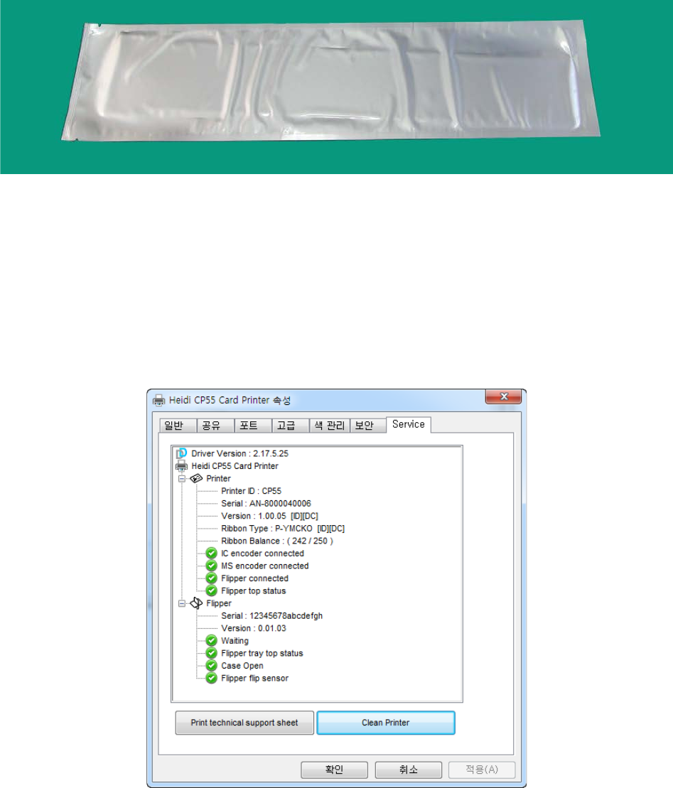
6.2. Cleaning the printer
To maintain the best condition of CP55 printer, you must clean the printer periodically. If
you use the exclusive cleaning card as the picture, you can clean the printer easily. For
purchase the exclusive cleaning card, ask to CP55 printer provider.
Figure 86 Exclusive cleaning card for CP55 printer
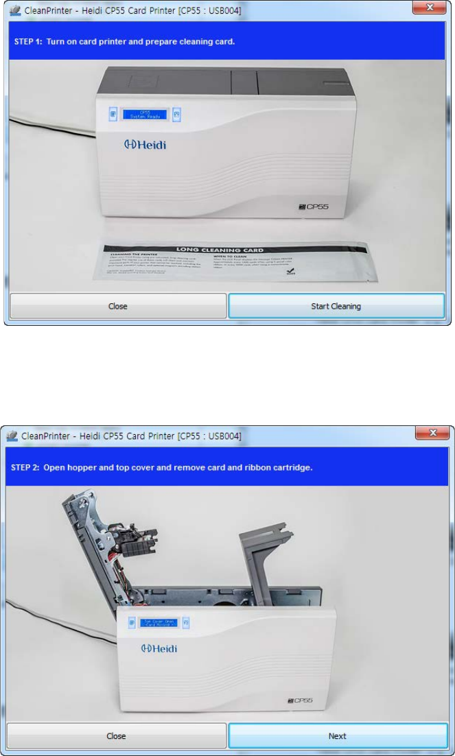
If the exclusive cleaning card is ready, click the “Clean Printer” in the service tab of CP55
printer driver. After click, Clean Printer program to clean the printer is run.
Or, You can set the Cleaning Mode with LCD buttons by pushing both buttons for 5 seconds.
Figure 87 Printer cleaning start
65
Step 1. Connect the CP55 printer to PC and turn it on, and prepare the exclusive cleaning
card.
Figure 88 Printer cleaning Step 1
Step 2. Open the hopper and top cover and remove the card and ribbon cartridge.
Figure 89 Printer cleaning Step 2
66
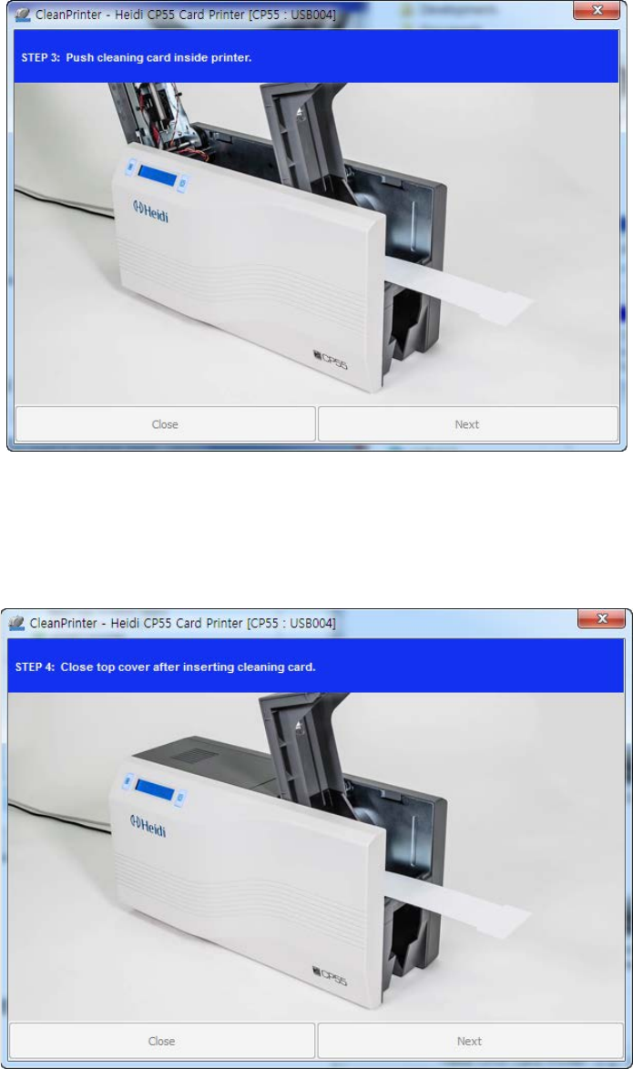
Step 3. Insert the exclusive cleaning card into the printer through input hopper. When the
exclusive cleaning card is inserted to the cleaning roller, it will be move
automatically. It is normal that the exclusive cleaning card is inserted to the ends
and rollers are moving to clean.
Figure 90 Printer cleaning Step 3
Step 4. Close the top cover to clean the Thermal Print Head and the printing roller. When
the top cover is closed, cleaning card will be moving back and forth to clean.
Figure 91 Printer cleaning Step 4
67
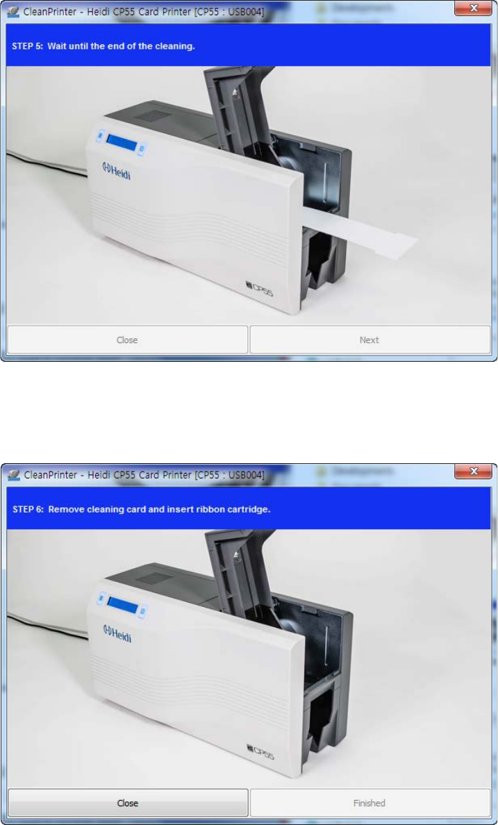
Step 5. Wait until the cleaning is completed. When the cleaning is completed, the
exclusive cleaning card will be ejected automatically as the picture.
Figure 92 Printer cleaning Step 5
Step 6. Remove the exclusive cleaning card and install ribbon cartridge into the printer.
Figure 93 Printer cleaning Step 6
68
6.3. TPH (Thermal Print Head) replacement
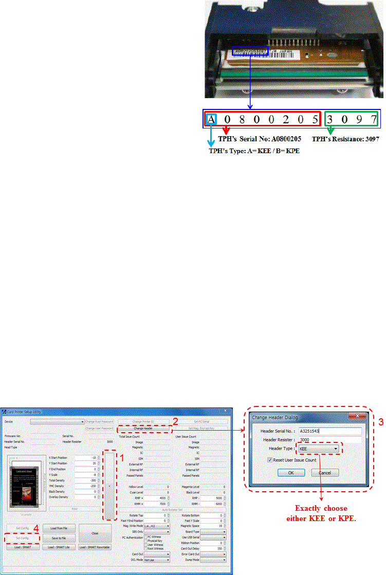
1. Check the serial number and the
resistance of new Thermal Print H
ead as
the Figure.
TPH type: A = KEE, B = KPE
Serial No.: see the red box.
TPH resistance: see the green box.
Figure 94 Thermal Print Head
2. Set up the new TPH’s configuration using CardPrinterSetup program.
Step1: Run ‘Card Printer Setup’ in Utilities of the installation CD and click expansion
button.
Step2: Click “Change Header” in the extended setup.
Step3: Input the TPH’s Serial No., Resistance and Type (choose KEE or KPE) on the
TPH’s label, and click “OK”.
Step4: Click “Set Config” to set the new TPH’s configuration.
Figure 95 Print head setup
69
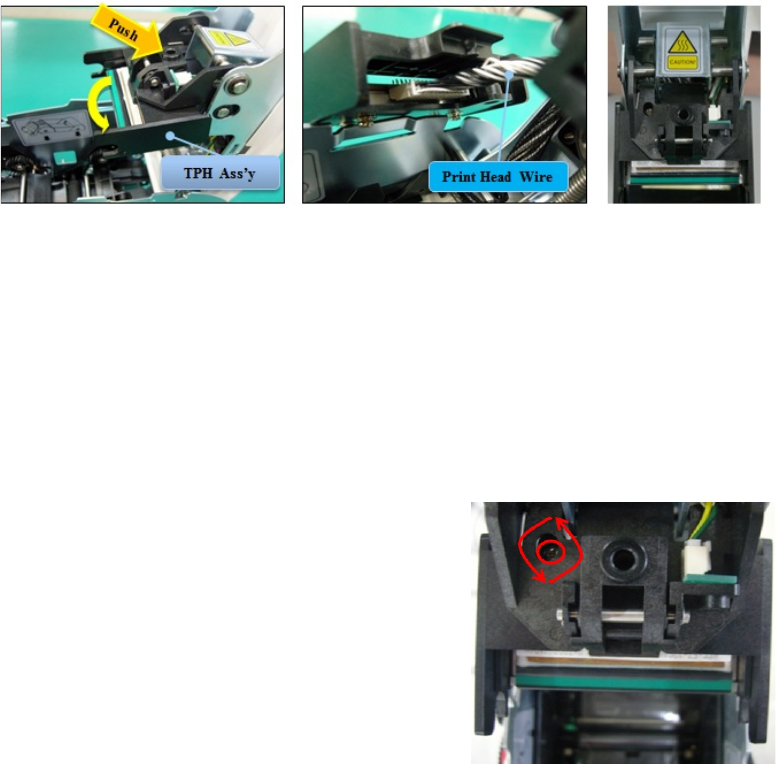
3. Replacing the new TPH
Step1: Remove the old TPH from the top cover.
(1) Turn off the printer and open the top cover.
(2) Hold the TPH and press the locked hook, then the TPH is disconnected..
(3) Disconnect the TPH from print head wire carefully.
(Caution: TPH is possible to HOT.)
Step2: Installing the new TPH
(1) Connect new TPH to the print head wire.
(2). Put the new TPH on the Shift and pull it up until be locked..
Figure 96 Print head replacement
4. Setup the print position and the color density.
After installing the new TPH, you must reset the print position and the color density using
CardPrinterSetup utility. Refer to “4.1.2 Default setting”
5. Calibration of Print Head Angle
To get the best print quality, the TPH
should be located vertically with card
surface.
If print quality has the problem, it
could be caused by print head angle.
Through Adjusting print head angle
by screw (red mark in the right
picture
), you could make good quality
of print.
(Use the appropriate screw driver to
adjust, and turn the screw by 90
degrees at a time.)
Figure 97 Print head angle
70
6.4. Card movement
6.4.1. Cards can’t enter into the printer from input hopper.
Non-standard cards or bad cards.
Change the cards. You can use only ISO CR-80 card (54mm x 86mm).
Card thickness control lever is set improperly.
Regulate the card thickness control lever to fit the current card thickness.
Bad card array.
Array the cards again and put them on input hopper as section 2.2 in this manual.
Cards have static and moisture.
Remove the moisture or static.
6.4.2. Card Transfer Error occurs when the ribbon is coiled around the transfer
roller or the printing roller.
Open the top cover and remove the card and the coiled ribbon from CP55 printer
using front LED buttons. If this problem occurred frequently, check the below things.
Non-standard cards or bad cards.
Change the cards. You can use only ISO CR-80 card (54mm x 86mm).
The transfer roller or the printing roller is contaminated with the dust and dirt
Remove the dust and dirt with the cleaning kit as section 6.1
Wrong printing position setting.
Please contact the local supplier
When operating temperature and humidity is out of the acceptable operating
limit of the printer.
Adjust the operating environment of the printer.
6.4.3. An Error occurs while the card is being transferred.
First of all, check the Error message at LCD display.
Open the top cover and remove the card by LED buttons.
If this problem occurs frequently, check the followings.
Non-standard cards or bad cards.
Change the cards. You can use only ISO CR-80 card (54mm x 86mm).

71
Printer setting is changed or is not proper.
Please contact the local supplier.
The transfer roller or the printing roller is contaminated with the dust and dirt.
Remove the dust and dirt with the cleaning kit as section 6.1.
The card surface is contaminated with the dust and dirt.
Check the card surface and remove the dust and dirt and try again. If this problem
occurs again, retry with new card.
6.5. Printing quality
6.5.1. Not printed or wrong colors printed spot.
The card surface is contaminated with the
dust and dirt.
After checking the card, change it to another
card.
The cleaning roller is contaminated with the
dust and dirt.
Check the cleaning roller. If there is much
dust, change the cleaning roller to the new
one.
Much dust in the printer.
Clean the inside of the printer with the cleaning kit.
6.5.2. Not printed horizontal line.
The ribbon cartridge is installed improperly.
Check the ribbon cartridge installation state
and whether the ribbon has wrinkles.
The printer head is contaminated with the
dust and dirt.
Clean the printer head with cleaning kit.
The printer head is damaged.
Please contact the local supplier to replace the printer head.
Figure 98 Printing quality trouble 1
Figure 99 Printing quality trouble 2

72
6.5.3. Unclear or not uniform print.
Uneven or bad card surface.
Change the card.
Too high or low setting of the color density.
Please contact the local supplier. The color
density default of your printer needs to be
changed.
The printer head is contaminated with the
dust and dirt.
Clean the printer head with cleaning kit.
6.5.4. Not aligned color print.
Non-standard cards or bad cards.
Change the cards. You can use only ISO CR-
80 card (54mm x 86mm).
Uneven or bad card surface.
Change the card.
The transfer roller or printing roller is
contaminated with the dust and dirt.
Clean the rollers with the cleaning kit as section 5.2.
Worn-out printer.
Please contact the local supplier.
6.5.5. Unplanned color print.
Non-standard cards or bad cards.
Change the cards. You can use only ISO CR-80
card (54mm x 86mm).
Uneven or bad card surface.
Change the card.
The transfer roller or printing roller is
contaminated with the dust and dirt.
Clean the rollers with the cleaning kit as section 5.2.
Worn-out printer.
Please contact the local supplier.
Figure 100 Printing quality trouble 3
Figure 101 Printing quality trouble 4
Figure 102 Printing quality trouble 5
73
6.6. Magnetic stripe encoding
6.6.1. Magnetic encoding error.
First of all, Please press left LED button to retry.
The magnetic head is contaminated with the dust and dirt.
Clean the magnetic head with the cleaning kit.
The magnetic encoding data is not transmitted or the wrong data is
transmitted.
Check the setting of the program and the driver and the magnetic encoding data you
transmitted.
The card is not magnetic card, or inserting direction is wrong.
Change the card or the direction.
Bad magnetic stripes on the card.
Change the card.
6.7. General operation
6.7.1. Ribbon snapped during printing.
Open the top cover and take out the cartridge. After putting the snapped pieces on
together, install the cartridge again. Check the followings if this kind of problem occur
frequently.
Non-standard cards or bad cards.
Change the cards. You can use only ISO CR-80 card (54mm x 86mm).
Too high or low setting of the color density.
Please contact the local supplier. The color density default of your printer needs to
be changed.
6.7.2. LCD display “Ribbon Not Found”
Press the left LED button to retry. If it occurs frequently, check the followings.
Not genuine ribbon.
Change to the genuine ribbon.
74
Ribbon is consumed.
Printing is not possible if ribbon is used up. Change the ribbon.
Snapped ribbon.
Open the top cover and take out the cartridge. After putting the snapped pieces on
together, install the cartridge again.
6.7.3. Printer doesn’t operate even if the printing data has been transmitted.
Check the following.
Printer power off.
Check the power. Turn on the printer power.
Check the printer adaptor whether it is connected with a socket and the printer.
Bad power adaptor.
Please contact the local supplier for replacement of the adaptor.
The printer driver is “Offline”.
Change the printer driver to “Online”.
The printer’s USB cable is disconnected or the connection is bad.
Check the cable’s connection between PC and the printer.
If not good, make the USB cable connection again.
Bad USB cable.
Change the USB cable.
The printing is operated with another printer driver.
Select the correct CP55 printer driver again.
Wrong USB port setting of the printer driver.
Check the port setting of the printer driver and change the port setting.
No ribbon in the printer or error occurred.
Install ribbon in the printer or resolve the error.
Too long power or USB cable (more than 1.5M).
Use the cable provided with the printer.
PC’s USB port is down:
Reboot your PC.

75
7. Specification
Model
CP55-S
CP55-D
Printing
Print Type
Direct to card dye-sublimation/resin thermal transfer
Print Area
Edge to Edge
Resolution
300dpi
Dual Side Printing
Option (with Flipper)
Yes
Card
Card Feeding
Automatic
Card Size
ISO CR80
Card Thickness
0.38mm (15mil), 1.0mm (40mil)
Card Type
PVC, Any cards with dye-receiving layer(PET, Composite PVC, PC)
Printing Speed
Monochrome
4.5 sec./card (800 cards/hour)
YMCKO
21 sec./card (170 cards/hour)
YMCKOK
_
27 sec./card (130 cards/hour)
Capacity
Input Hopper
100 Cards / 200 Cards with cover open
Output Hopper
Front : 40 Cards / Rear : 100 Cards (Optional Rear-side Stacker)
System
Memory
64MB RAM
Display
2 Line LCD
Control Panel
2 LED Buttons
Supported Platforms
MS Windows 7/ 8/ 10, Mac OS, Linux
Communication
USB, Ethernet (Option)
Power Supply
DC 24V, 2A
Power Consumption
48
48
Temp. / Humidity
15~35℃ / 35~70%
Dimensions
Millimeter (WxLxH)
166 x 380 x 208
166 x 486 x 208
Inch (WxLxH)
6.5 x 15.0 x 8.2
6.5 x 19.1 x 8.2
Weight
Kg / Lbs
5.1 / 11.2
6.0 / 13.2
Encoding Options
Magnetic
ISO 7811 (Track I, II, III Read/ Write, HiCo/ LoCo)
Contact
ISO 7816 (ID-1)
Contactless
MIFARE, ISO 14443 (Type A/ B), DESFIRE, iCLASS
Certifications
CB, CE, FCC
Specifications and availability may change without notice.
76
RFID(13.56MHz) Usage
The RFID Tag is used for the security and the recognition of the ribbon. To get the
optimized printing quality on the printed card, the genuine ribbon of IDP should be used
to print cards by using SMART printer. SMART printer can recognize the genuine ribbon
by reading the encoded information on the RFID Tag of the ribbons. To support user’s
various requirements for printing cards appropriately, many kinds of ribbons should be
provided and SMART printer should distinguish the type of installed ribbon. To
distinguish the installed ribbon type correctly, SMART printer reads the encoded
information on the RFID Tag of the ribbons. According to the installed ribbon type and
the ribbon supplier, the printer driver of SMART printer can select the color profile and
create the printing data.