IDP SMART-51L Laminator User Manual
IDP Corp., Ltd. Laminator
UserManual.wiki
>
IDP
>
SMART 51L User Manual
User Manual
Navigation menu
Upload a User Manual
Namespaces
Wiki Guide
HTML
PDF
Info
Views
User Manual
Discussion / Help
Navigation

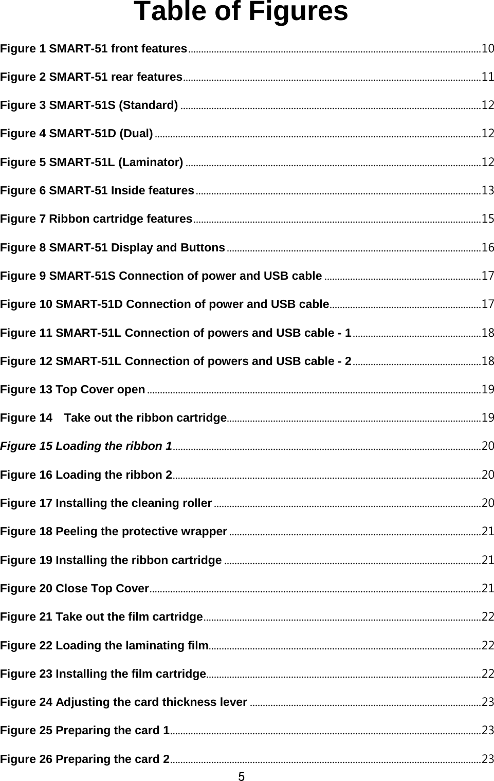
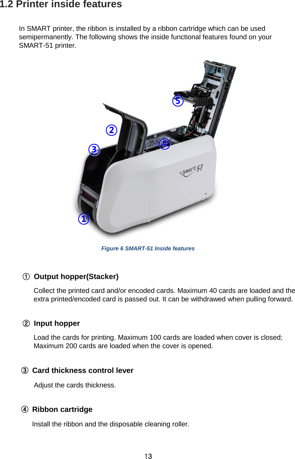
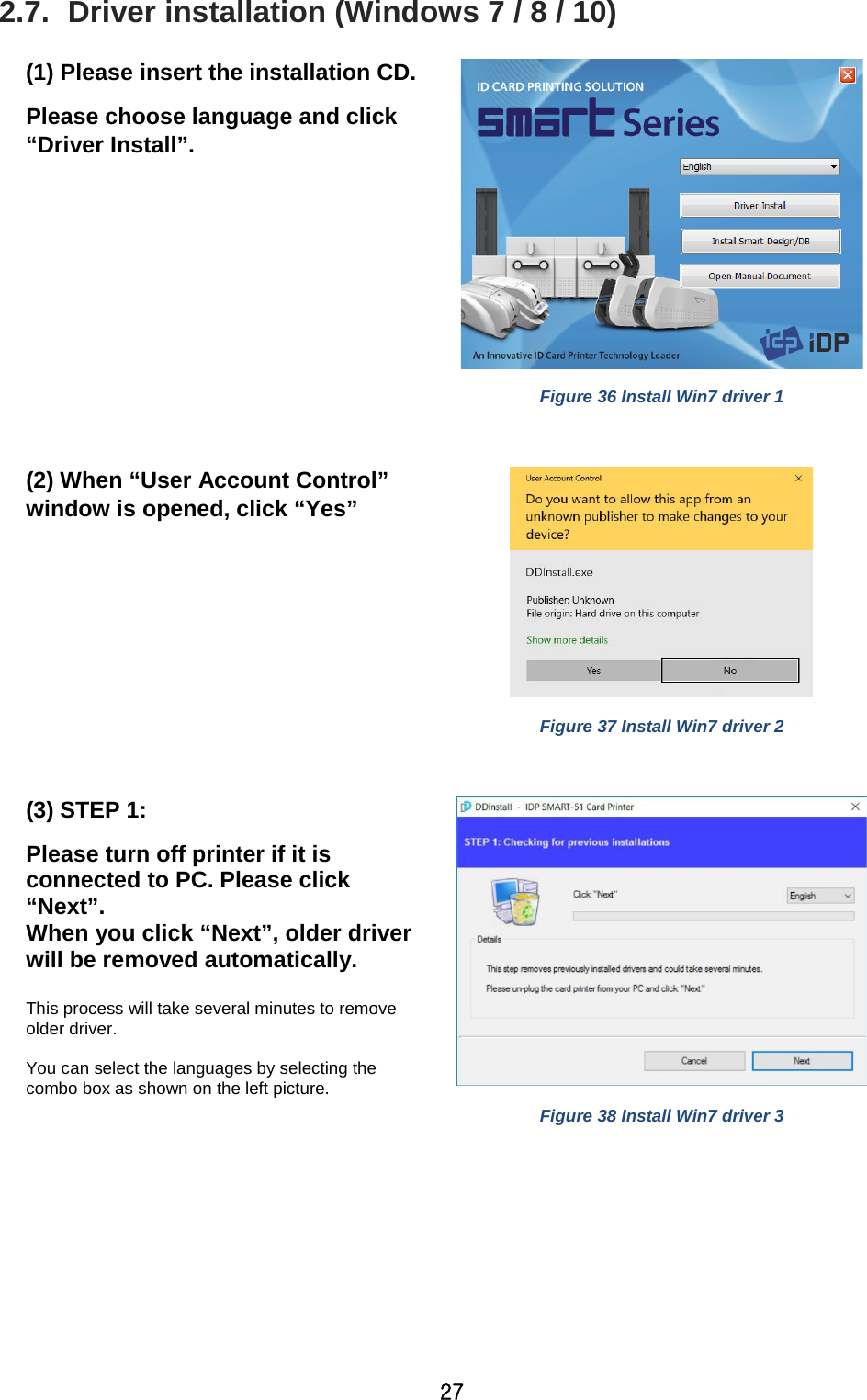
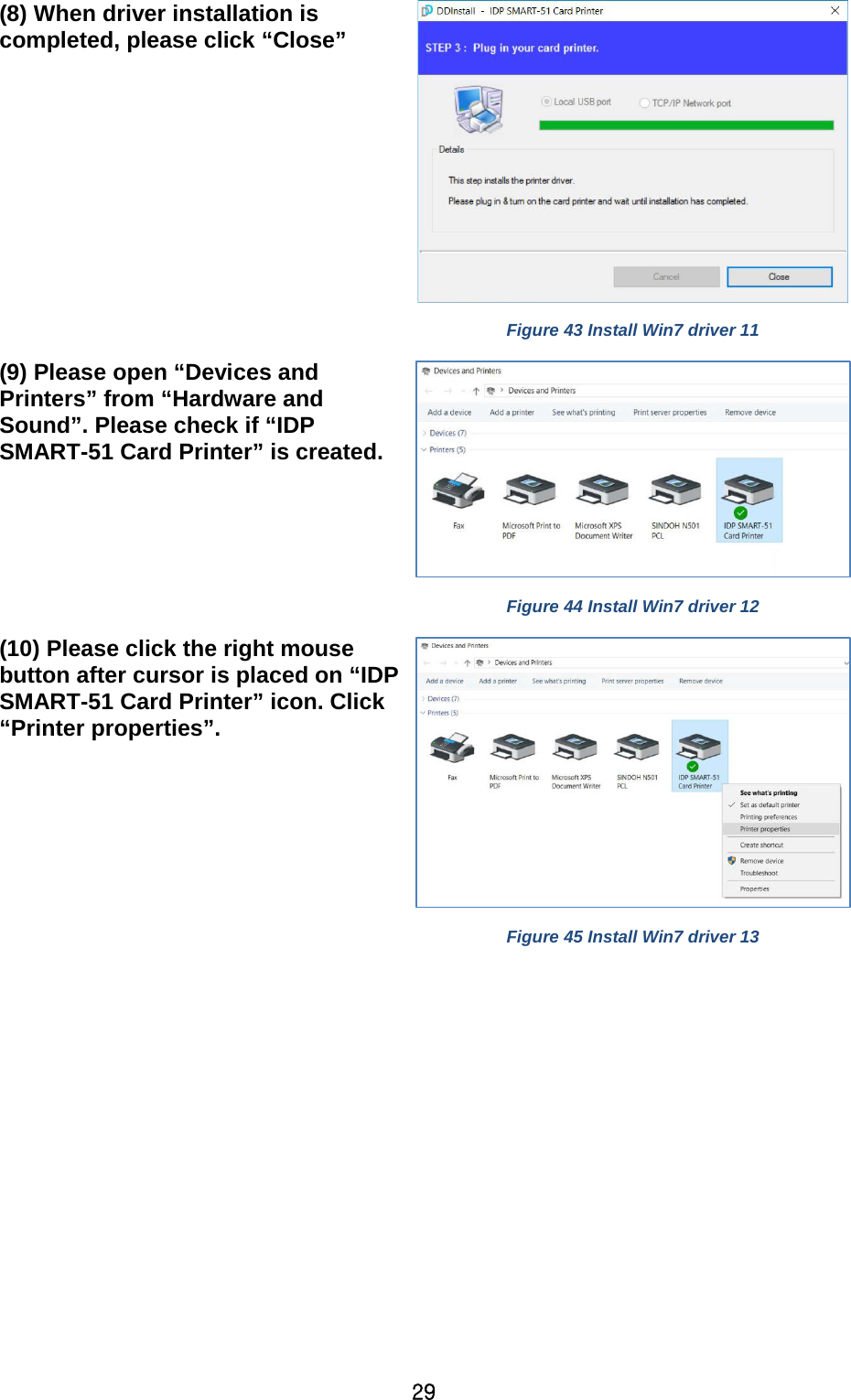
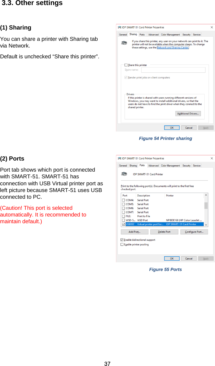
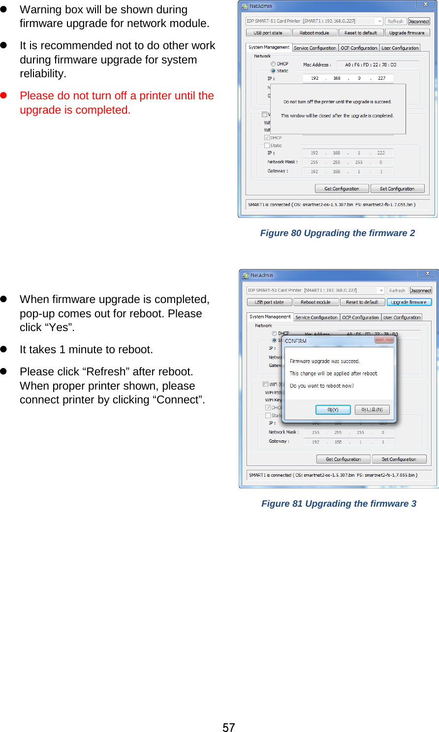
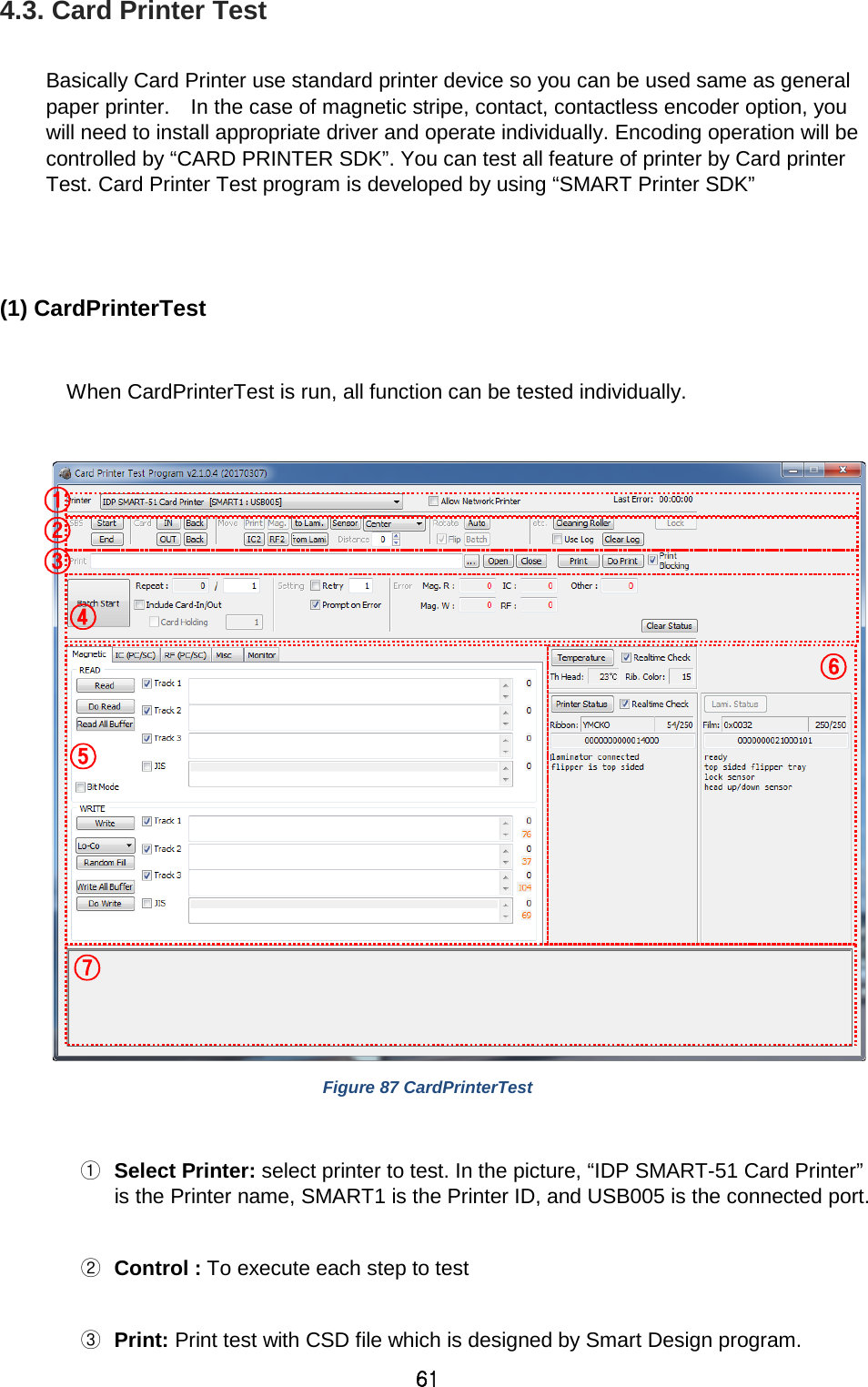
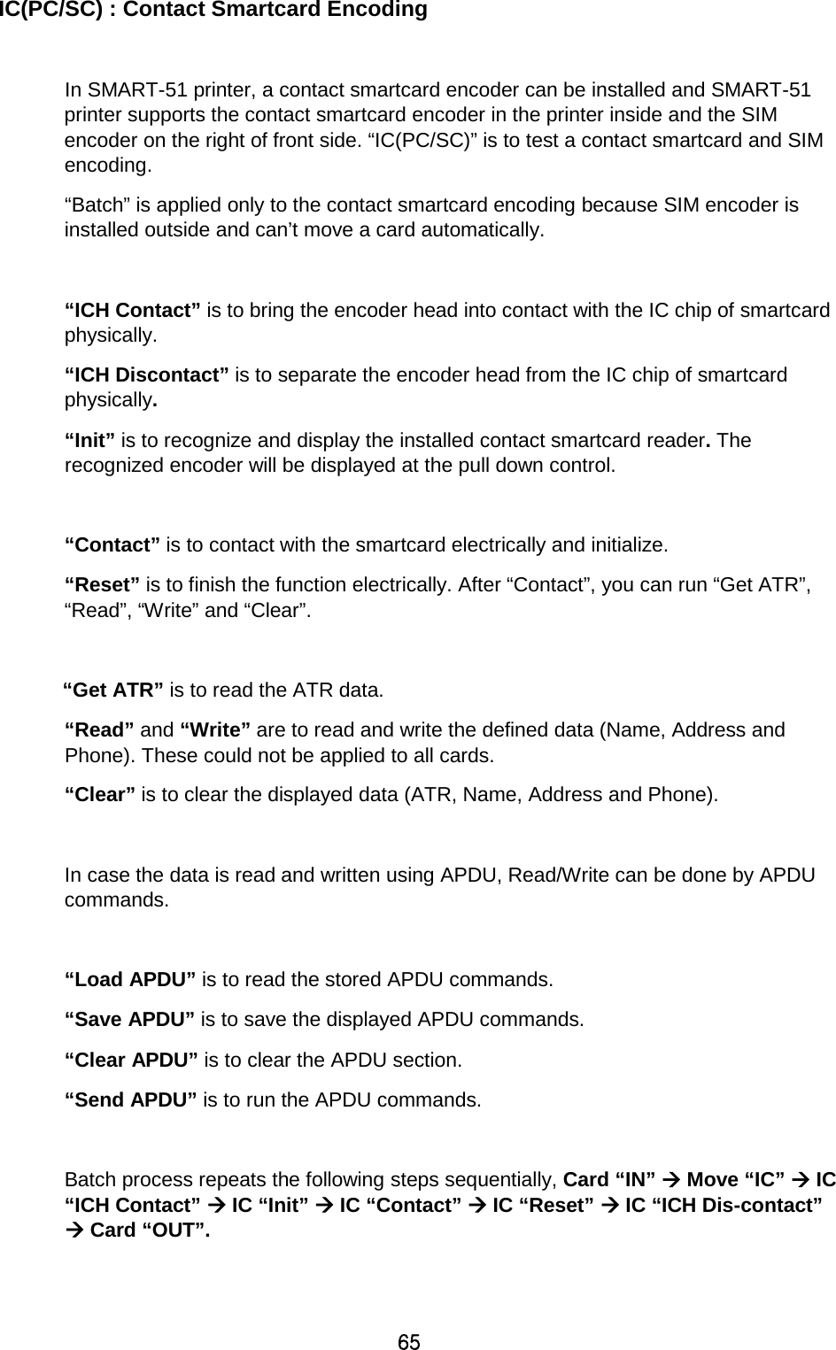
![32 (3) Input / Output [ Supply Tray ] Supply : You can select “Auto” if SMART-51 has 1 input hopper. Please select the hopper if it has a multi hopper. Tray : You can select “CR-80” because SMART-51 supports CR80 cards only. Figure 50 Input / Output (4) Printing Do Printing : You can select printing or not [ Print Side ] Side : Please select one side printing or both sides printing (It is possible only when you have a flipper.) [ Front / Back ] Color : You can select color or mono print. Flip : You can flip an image Media / Mask : You can indicate the area to print by using a predefined mask or user defined mask (white card, smartcard, Magnetic stripe card, etc.) on front or back side. [ Printing ] Ribbon : It shows the type of installed ribbon. You don’t need to select this option as SMART-51 recognizes ribbon automatically with RF Tag. Speed : Set printing speed and quality Mode : Set printing mode Standard : Default print mode. Prints all area of printing Figure 51 Printing You can define a mask. User defined mask uses BITMAP file (1012 X 636 pixels). Blue (RGB(0,0,255)): Print and Overlay Sky Blue (RGB(0,255,255)): Overlay only Pink (RGB(255,0,255)): Print only Yellow (RGB(255,255,0)): Florescent](https://usermanual.wiki/IDP/SMART-51L/User-Guide-3481317-Page-32.png)
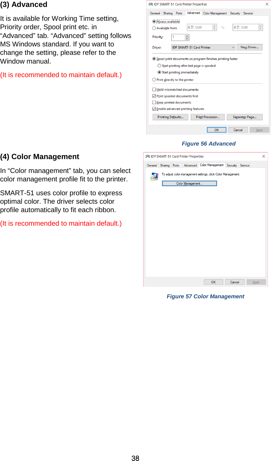
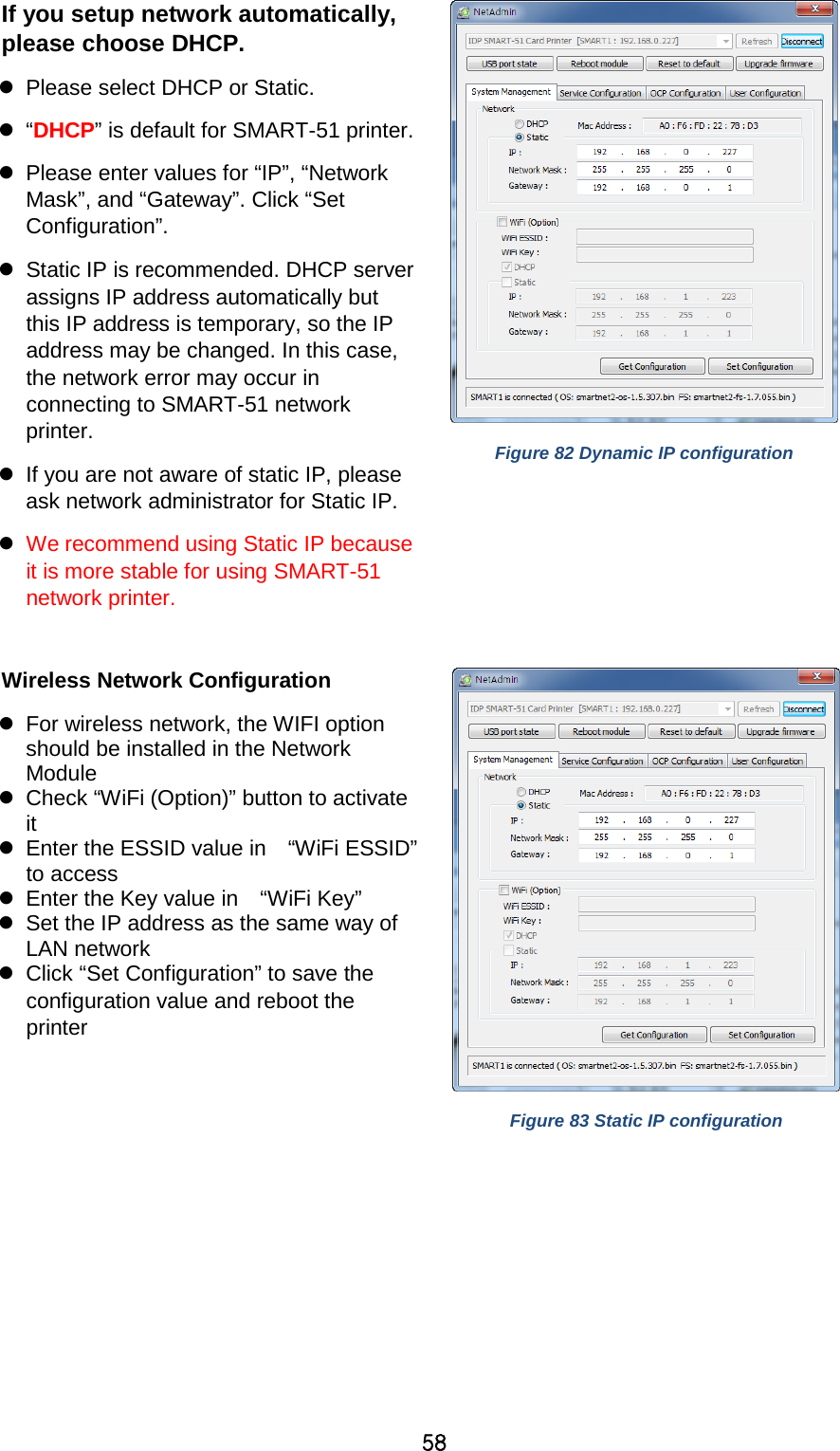
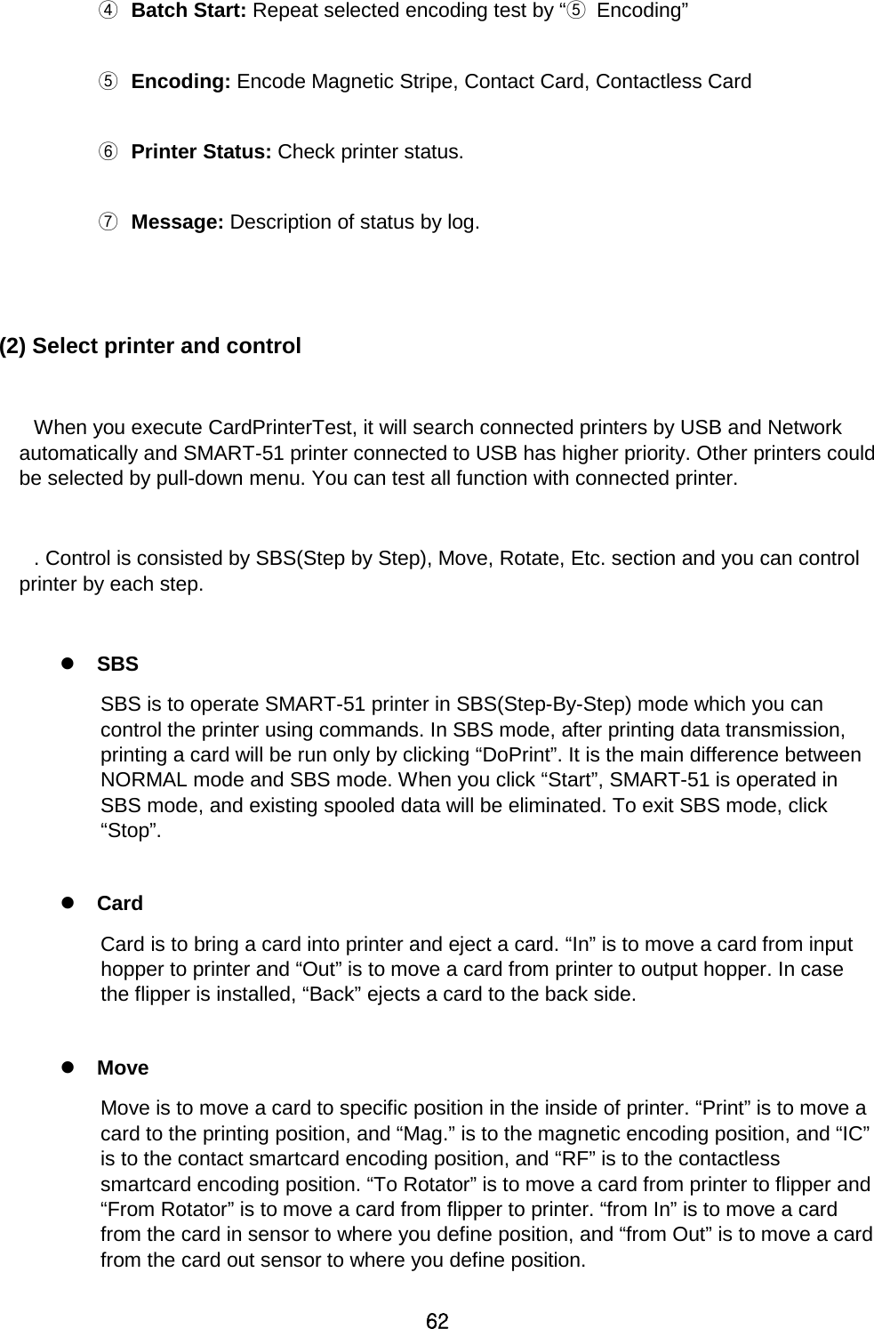
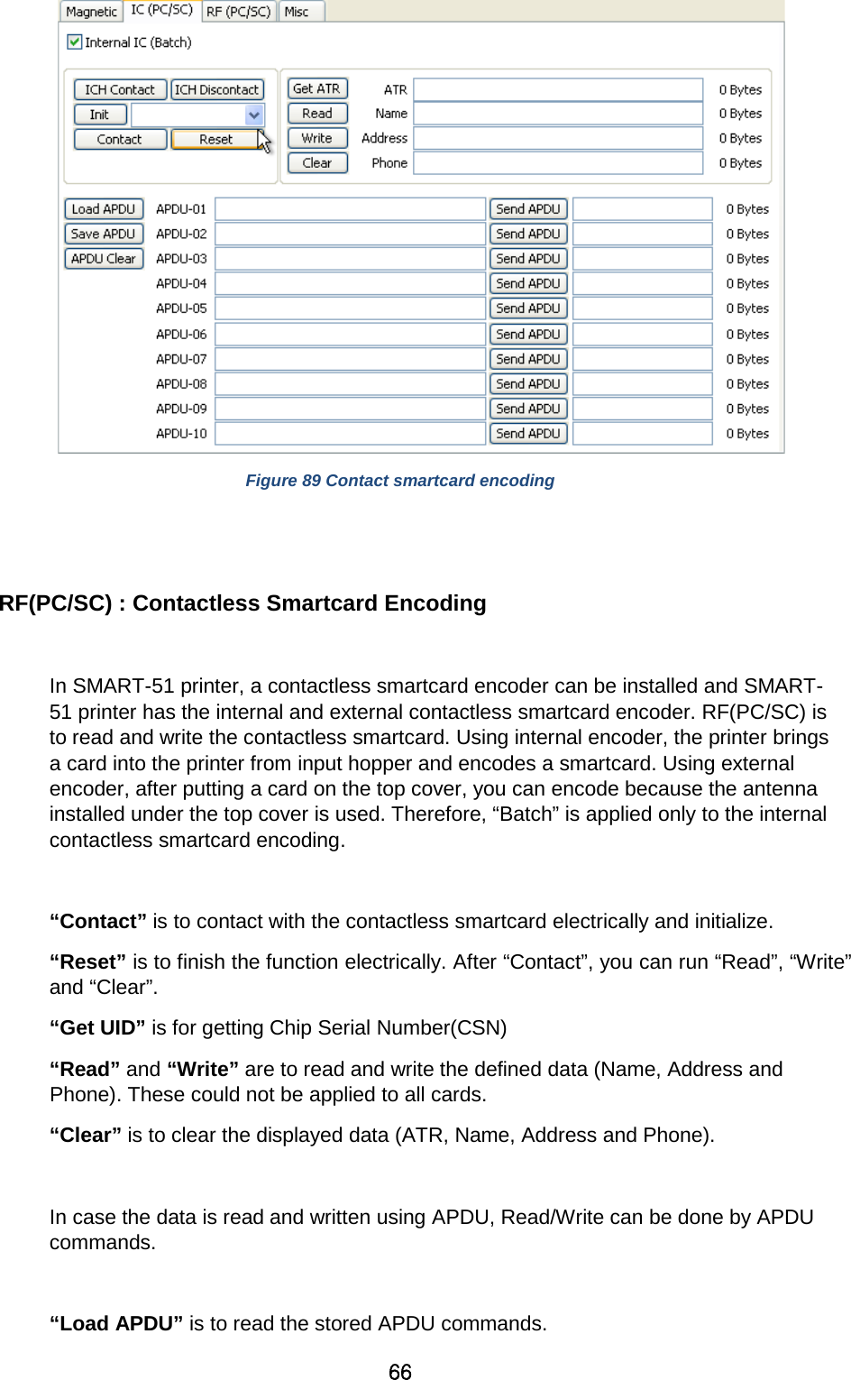
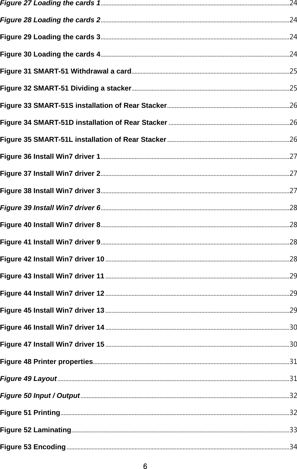
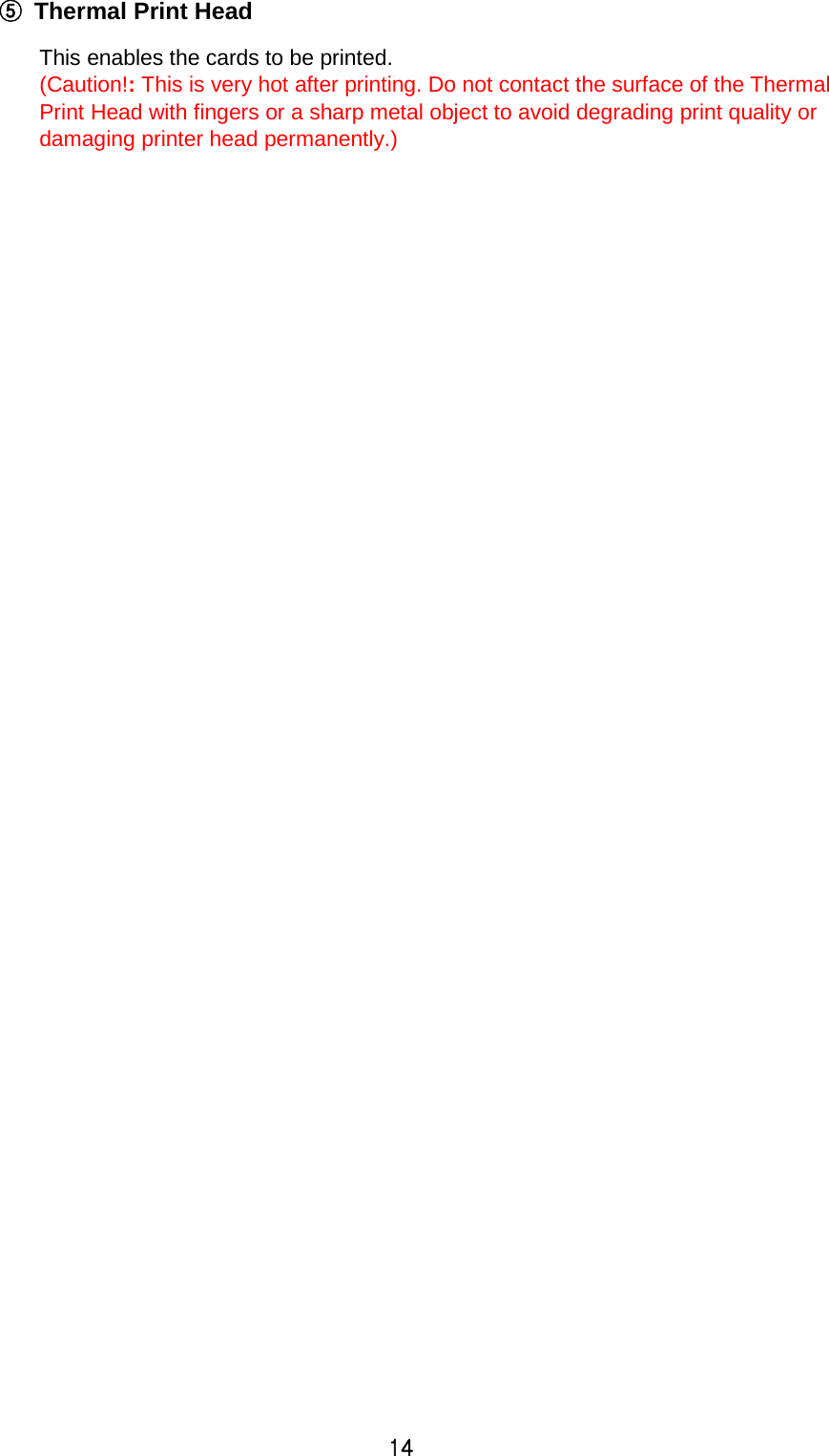
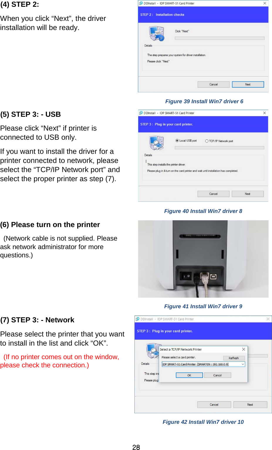
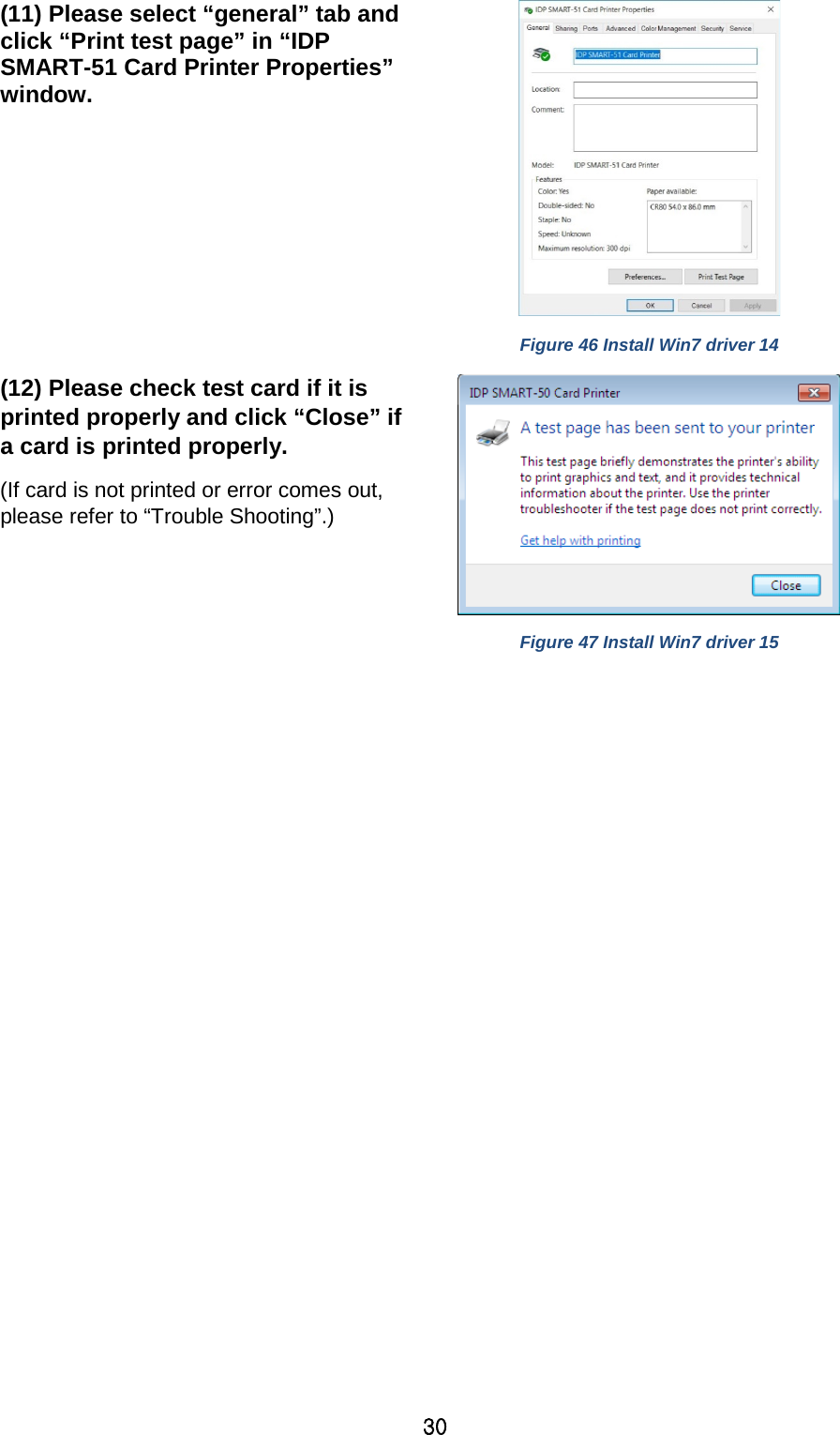
![34 (6) Encoding This tap will be shown only when Magnetic encoder is installed. Do Encoding : You can select encoding or not Coercivity : You can select the coercivity to encode Loco : 300, 600 Oe. HiCo : 2760 Oe. SpCo : 4000 Oe. Auto : Defined automatically Repeat Count : You can select the retry count to encoding when encoding is failed Figure 53 Encoding 3.2. Advanced Options To change the detailed configuration, In the ‘Layout’ tab shown, Please click “Advanced…” shown on the bottom of the ‘Layout’ tab of the ‘Preferences’. Reset Default Values: Reset to default. Color Correction: You can correct gamma for colors. You need to use CardPrinterConfig to adjust color densities. - Main [-100:100] : Correct gamma for all panels - Yellow [-100:100] : Correct gamma for yellow panel - Magenta [-100:100] : Correct gamma for magenta panel - Cyan [-100:100] : Correct gamma for cyan panel - Black [-100:100] : Correct gamma for black panel - Overlay [-100:100] : Correct gamma for overlay panel](https://usermanual.wiki/IDP/SMART-51L/User-Guide-3481317-Page-34.png)
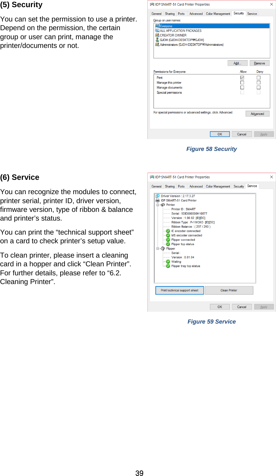
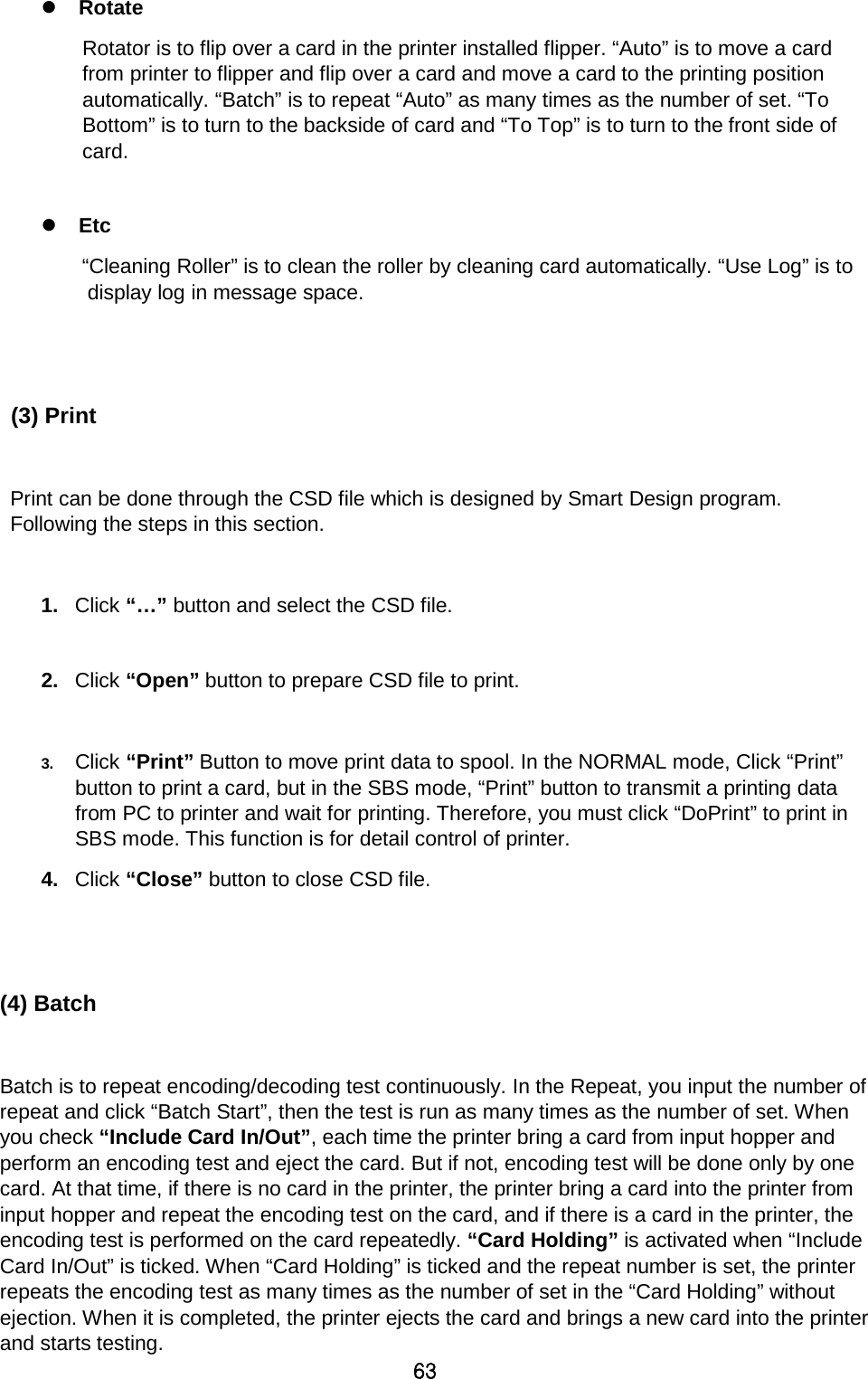
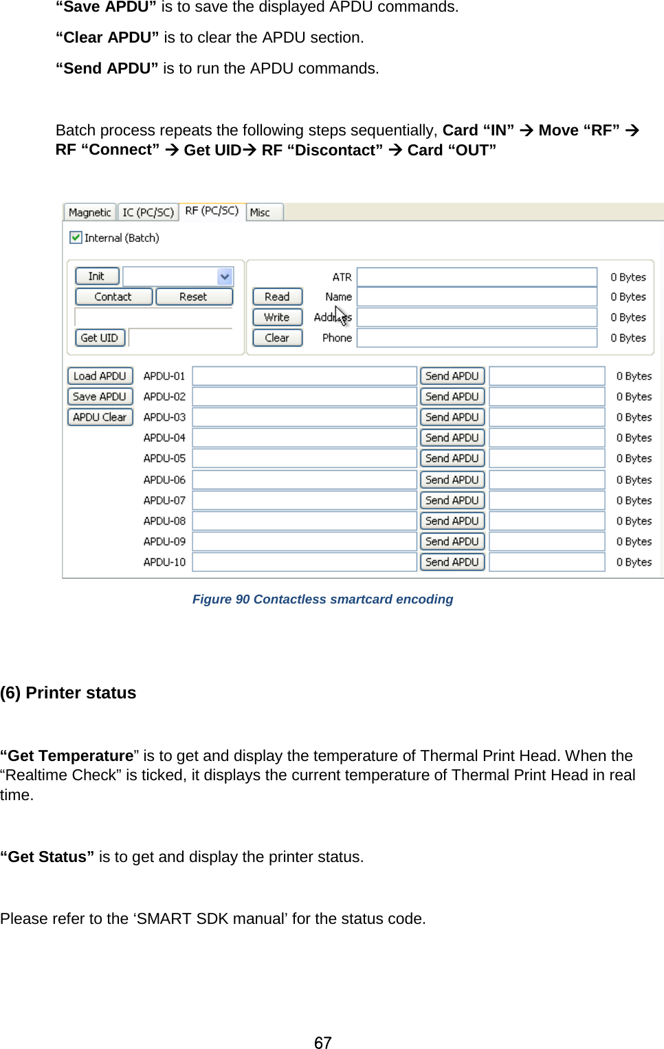
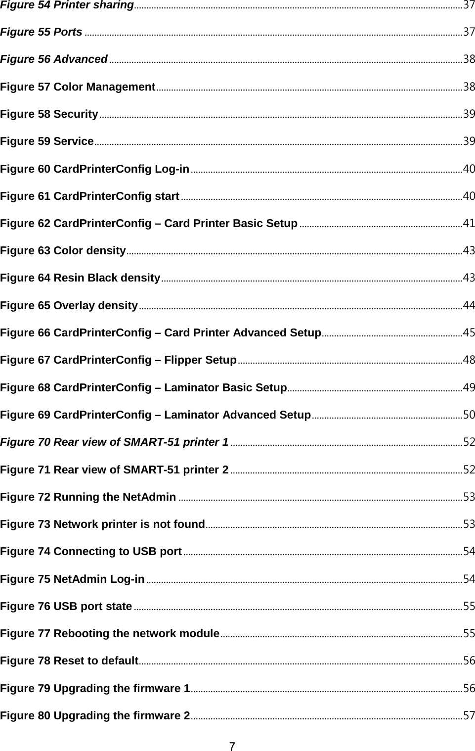
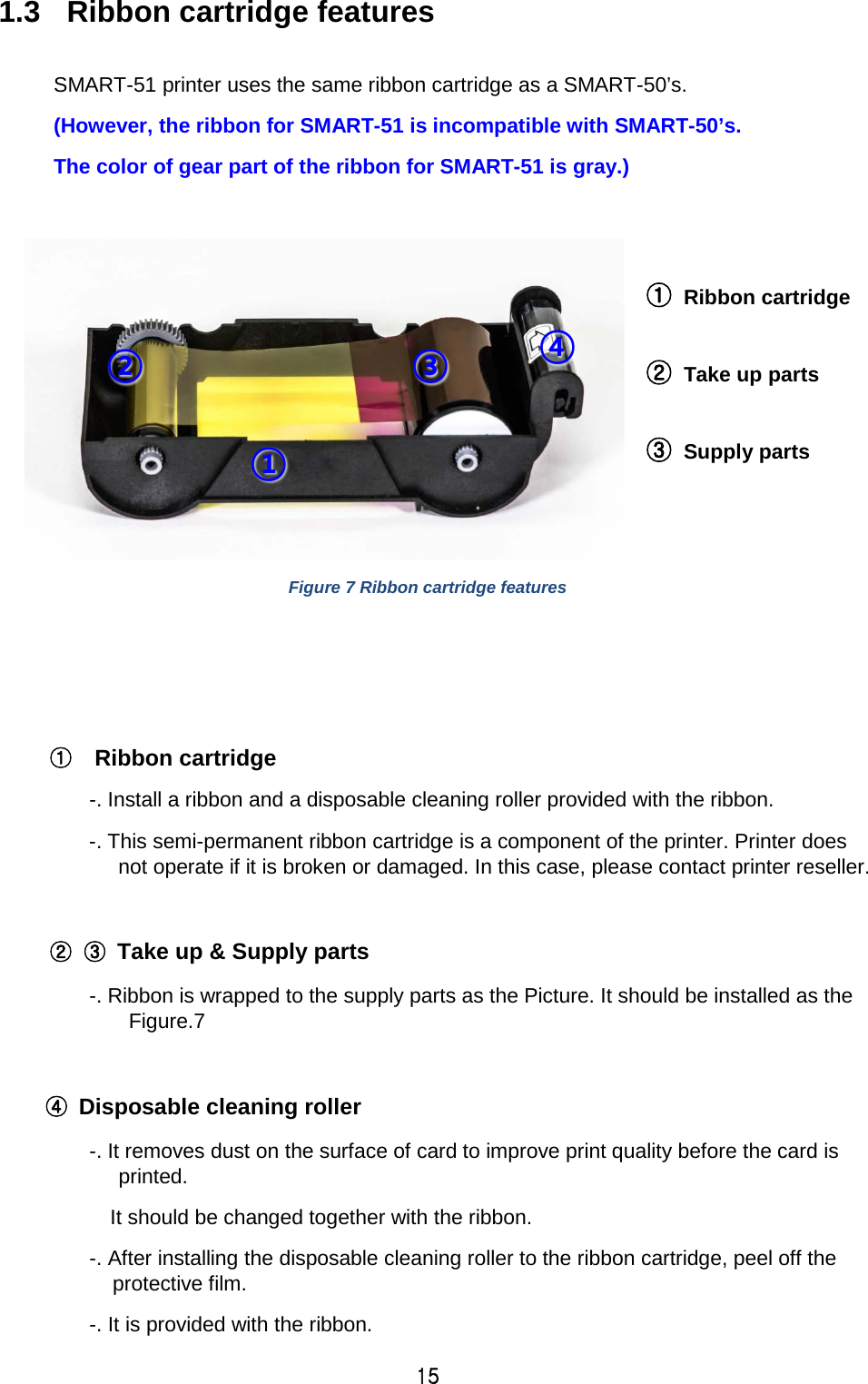
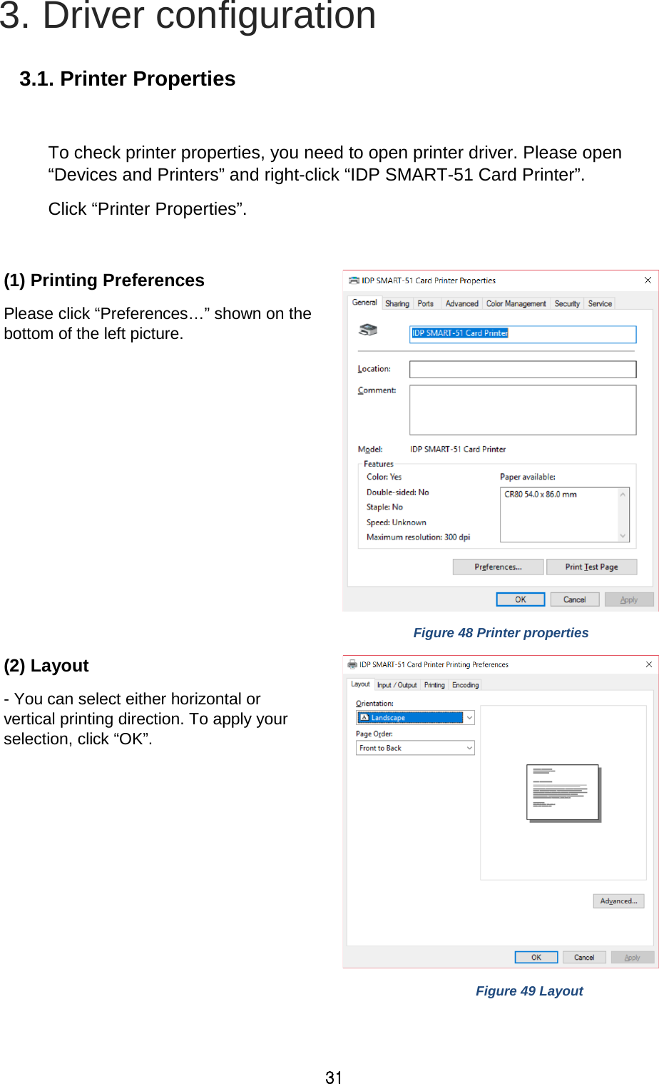
![35 Position Processing: Set criteria for resin black processing. - Color [-32:32]: to set the position of color panels - Mono [-32:32]: to set the position of resin or mono panel - Overlay [-32:32]: to set the position of overlay panel Resin Black(K) Processing: Set criteria for resin black processing. - Text [0:100]: to set density criteria for extracting black objects - Dot [0:100]: to set density criteria for extracting black dots - Threshold [0:100]: to set density criteria on dithering - Dithering Degree [0:100]: to set sharpness on dithering - Resin Extraction: You can set the method to extract resin black when you use design programs. (If you use the SmartID, you don’t need to select this option.) It will be set automatically. Black Object: to extract resin black automatically for text, line, box, circle, binary images, etc. Black Text: to extract resin black for text only Black Dots: to extract resin black for all of black Black Dots only: to extract resin black for all of black and not to print on color panels Not Use: not to extract resin black Extra Controls : Other options - Fast Alignment [On/Off]: to set the position of input card to the magnetic encoder or normal printing. If it is on, the printer can save the time to encode - Rewritable Erase Density [0:100] : to set Erase Density on Rewritable printer Wait Option: - Wait at Internal Module Contactless Encoding Position [On/Off]: to set whether to wait at the Internal RF encoder or not](https://usermanual.wiki/IDP/SMART-51L/User-Guide-3481317-Page-35.png)
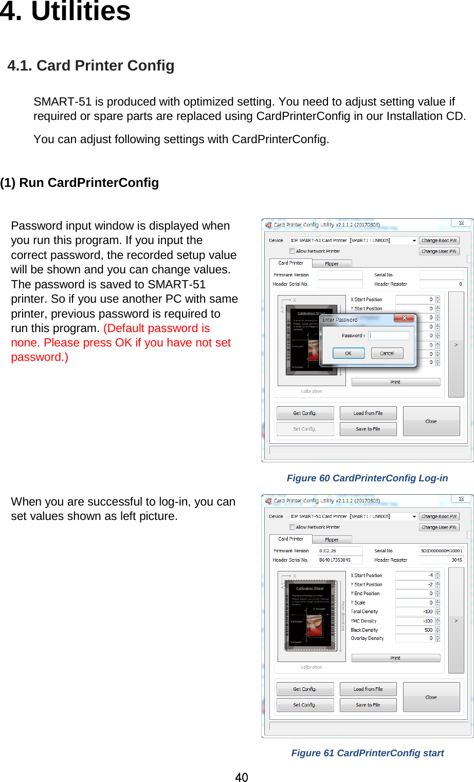
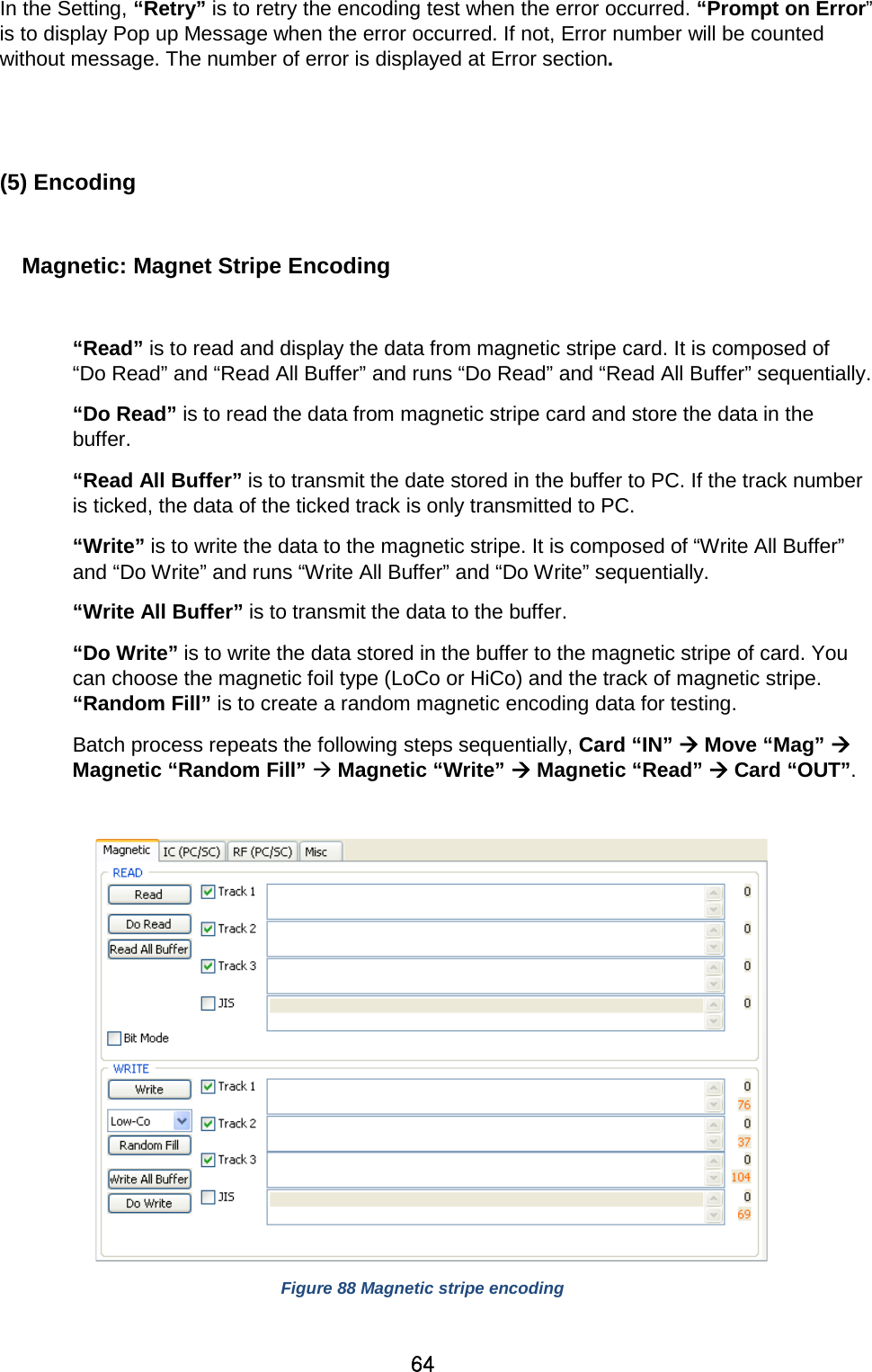
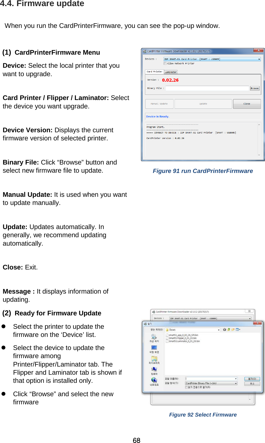
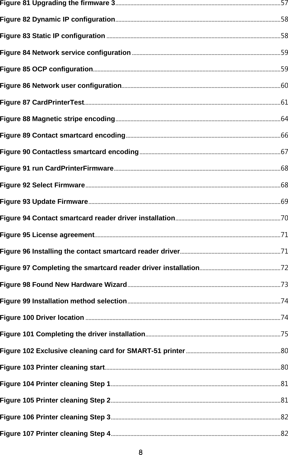
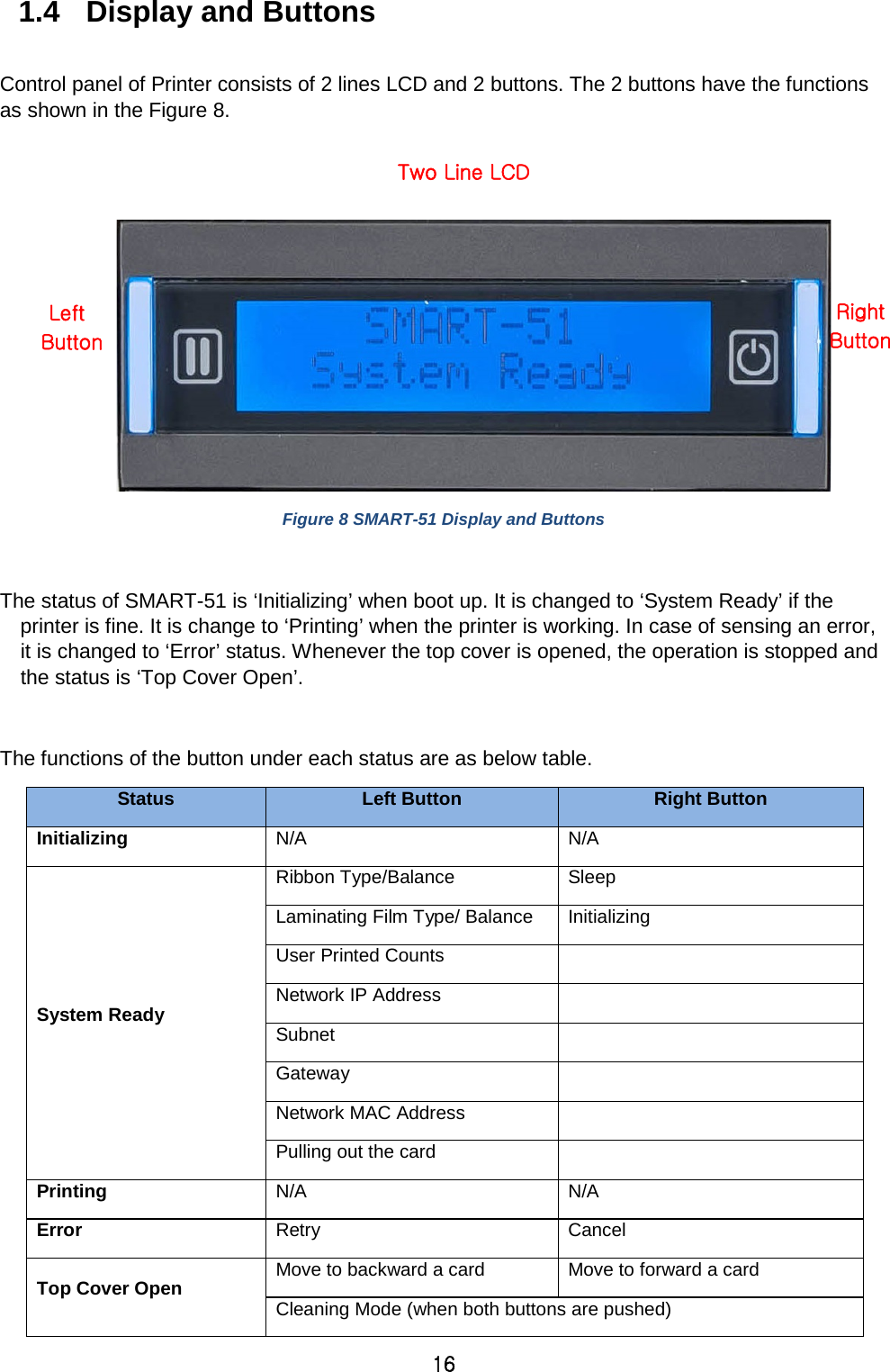
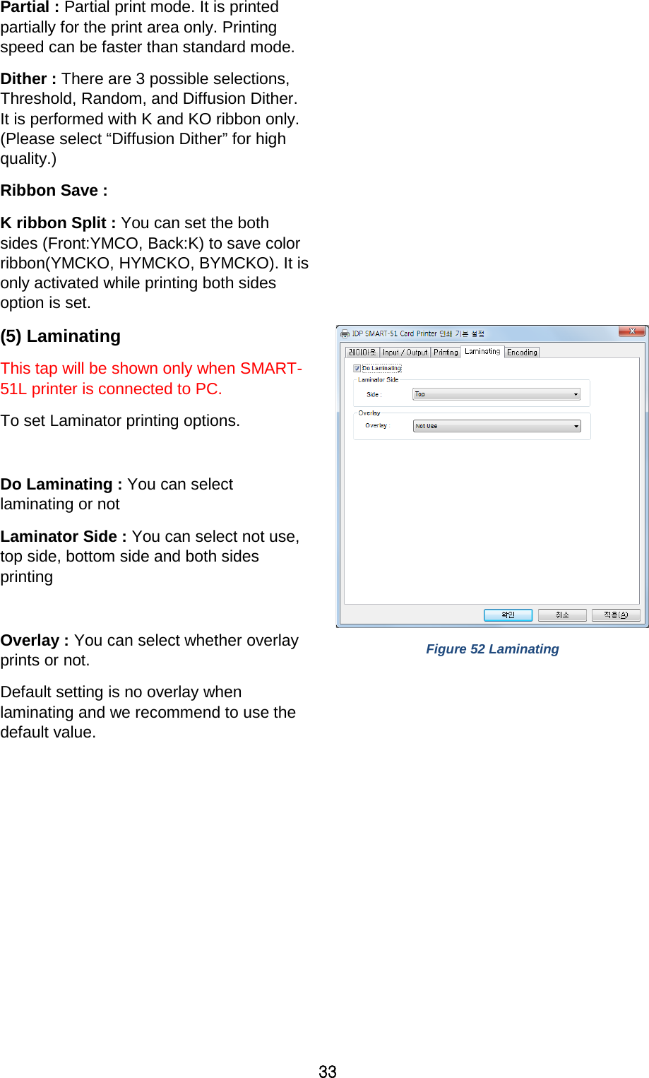
![36 Card Side [Front/Back]: to set the direction of card when waiting Wait Position [-100:100]: to set the position of card to wait from the criteria position. Unit is 0.1mm Wait Time [0:1000]: to set time to wait. Unit is second - Wait at External Module Contactless Encoding Position [On/Off]: to set whether to wait at the External RF encoder or not Card Side [Front/Back]: to set the direction of card when waiting Wait Position [-100:100]: to set the position of card to wait from the criteria position. Unit is 0.1mm Wait Time [0:1000]: to set time to wait. Unit is second - Wait at Internal Module Contact Encoding Position [On/Off]: to set whether to wait at the Internal IC encoder or not Card Side [Front/Back]: to set the direction of card when waiting Wait Position [-100:100]: to set the position of card to wait from the criteria position. Unit is 0.1mm Wait Time [0:1000]: to set time to wait. Unit is second](https://usermanual.wiki/IDP/SMART-51L/User-Guide-3481317-Page-36.png)