IDP SMART-70L Laminator User Manual 1
IDP Corp., Ltd. Laminator 1
UserManual.wiki
>
IDP
>
SMART-70L User Manual
>
User Manual 1
Contents
1.
User Manual 1
2.
User Manual 2
User Manual 1
Navigation menu
Upload a User Manual
Namespaces
Wiki Guide
HTML
PDF
Info
Views
User Manual
Discussion / Help
Navigation
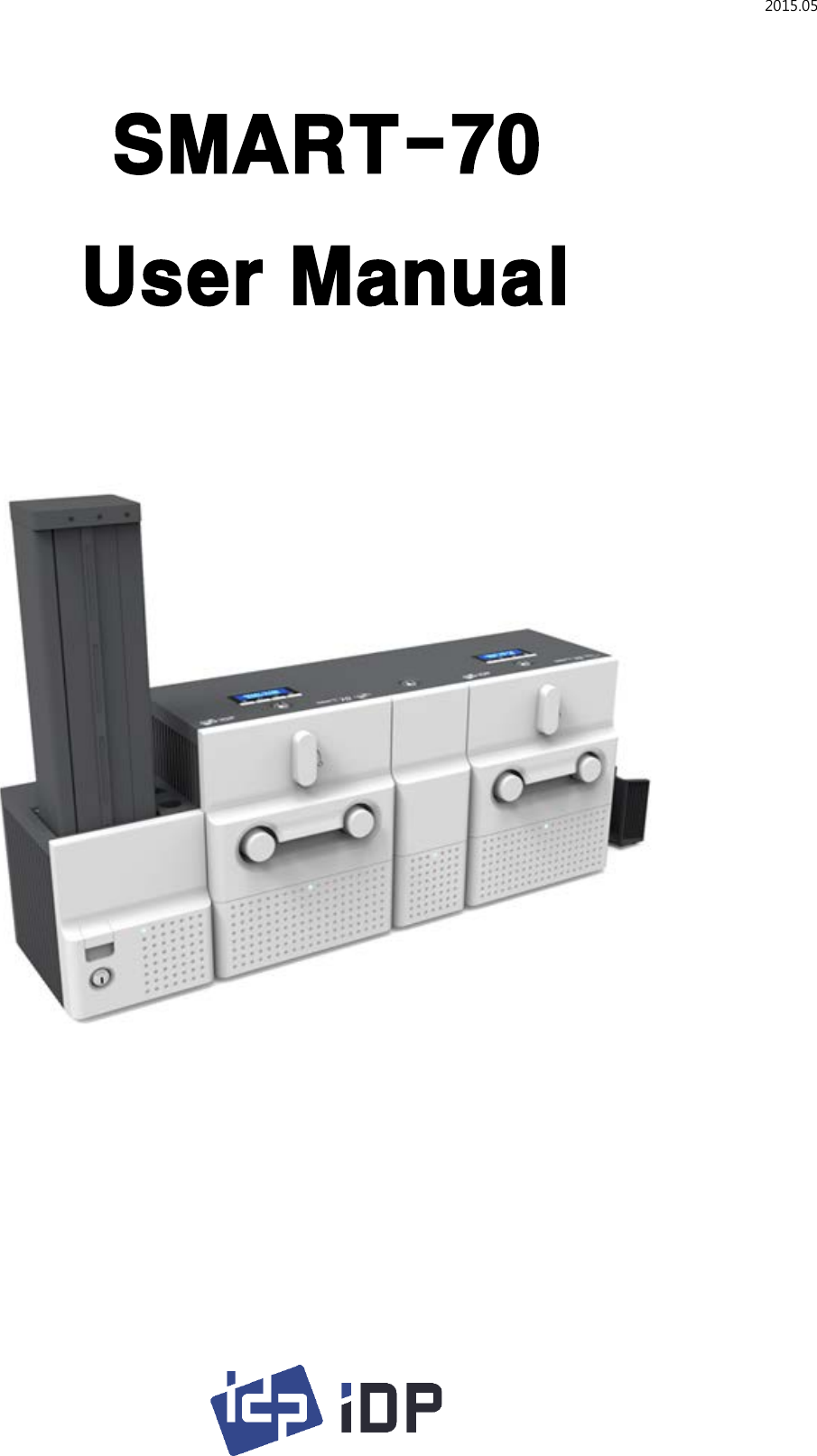

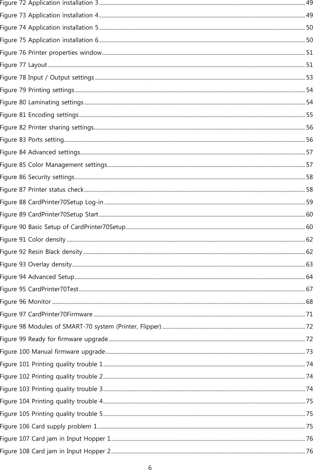
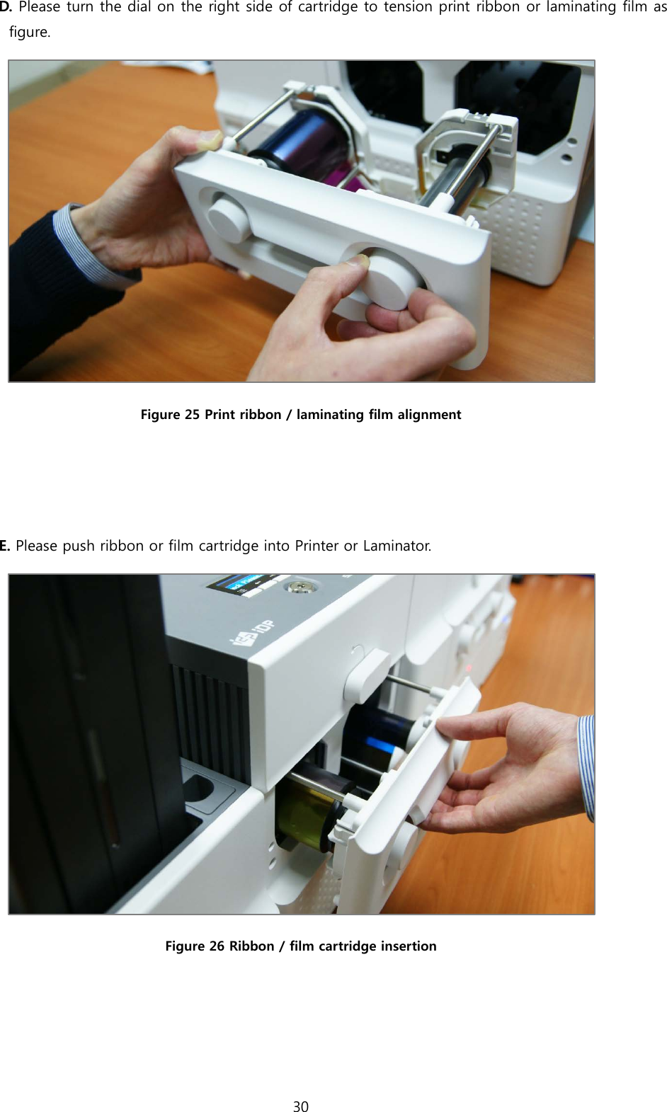
![2.1.10 Module combination setting Since SMART-70 is operated by the combination of multiple modules, the configuration for multiple modules combination must be set during the first installation of the modules. Printer module acts as master who is responsible to communicate with PC and control other modules, and if Printer module is not connected, Laminator module will act as master. The configuration for multiple modules combination can be set in the control panel of Printer module as below. SMART-70 Printer searches connected modules in booting, if the combination of connected modules is different with the configuration for multiple modules combination, Indicator LED is turned to yellow and the message for checking modules combination is displayed. Please follow below steps to set the configuration for multiple modules combinations for initial setting. A. The modules combination is IPFLO (Input Hopper + Printer + Flipper + Laminator + Output Hopper) but the configuration is different with the actually connected modules, so the configuration for multiple modules combination must be set again. Please press the [Select] button indicated by red arrow. Figure 43 Modules combination checking B. Existing modules combination is shown. Please press the [Select] button indicated by red arrow to adjust the configuration for multiple modules combination. Figure 44 Existing modules combination 39](https://usermanual.wiki/IDP/SMART-70L.User-Manual-1/User-Guide-2870684-Page-39.png)
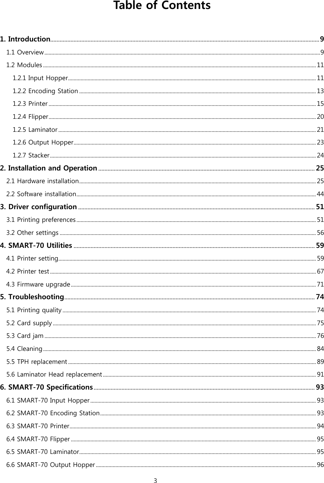
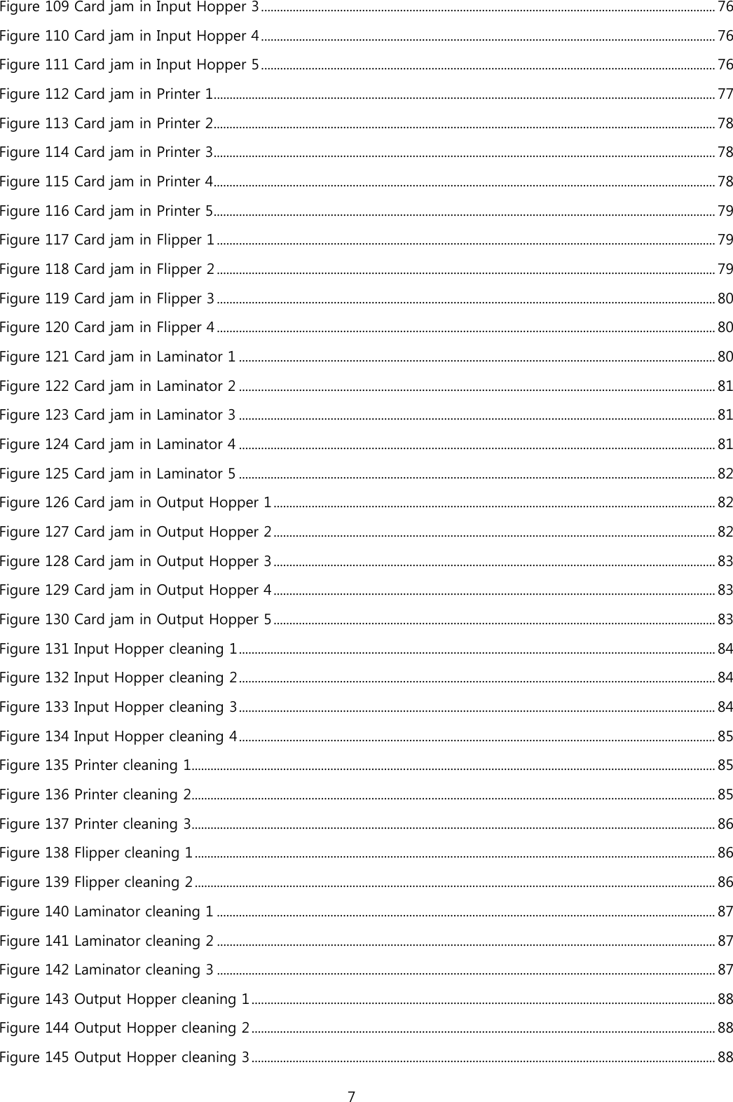
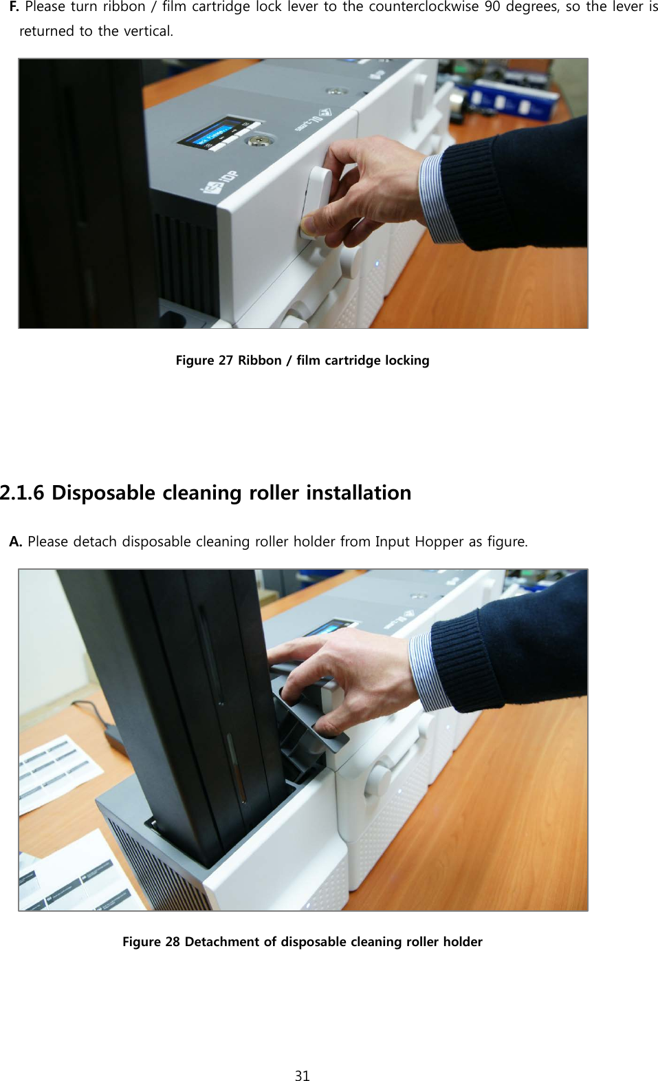
![C. The detected modules combination is shown. Please press the [Select] button indicated by red arrow to save the configuration for detected multiple modules combination. Figure 45 Adjusted modules combination D. The saved multiple modules combination is shown. Figure 46 Saved module combination E. Please wait a while until system is ready. Figure 47 Completed module combination 40](https://usermanual.wiki/IDP/SMART-70L.User-Manual-1/User-Guide-2870684-Page-40.png)

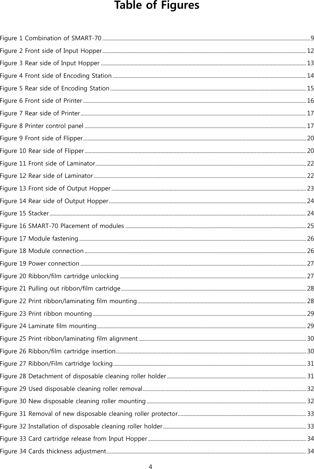
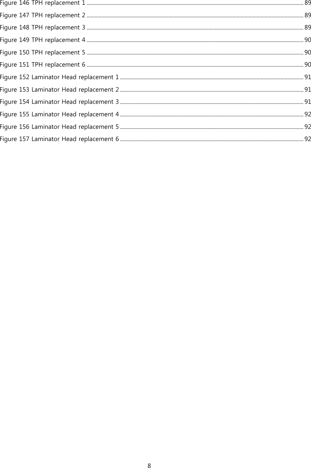
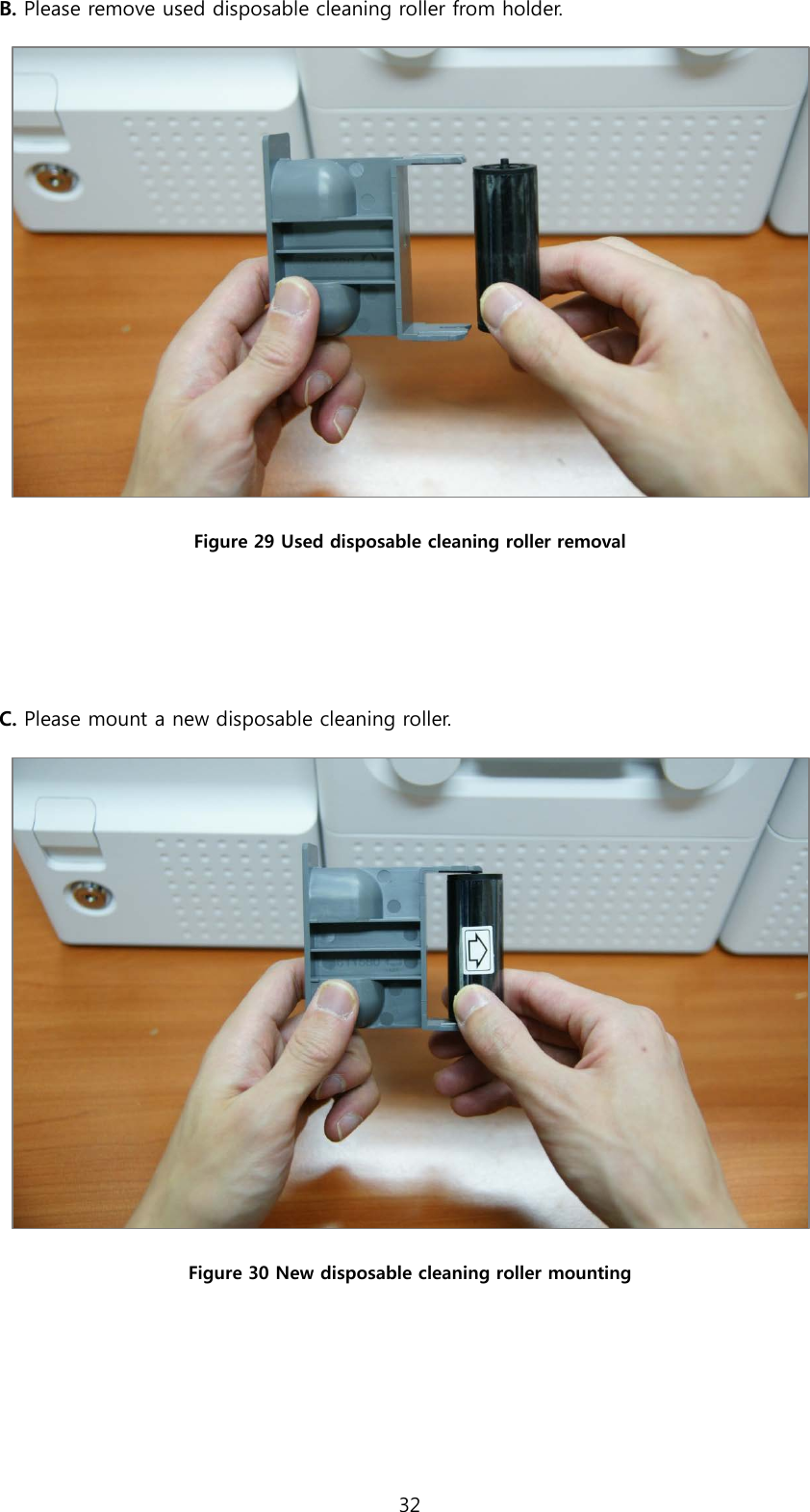
![B. On “System Config” menu, please press the [→] button indicated by red arrow. Figure 50 Printer menu (System Config) C. On “Network Config” menu, please press the [→] button indicated by red arrow. Figure 51 Printer menu (Network Config) D. On “Printer Config” menu, please press the [→] button indicated by red arrow. Figure 52 Printer menu (Printer Config) 42](https://usermanual.wiki/IDP/SMART-70L.User-Manual-1/User-Guide-2870684-Page-42.png)
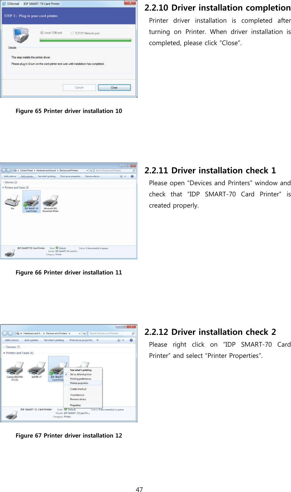
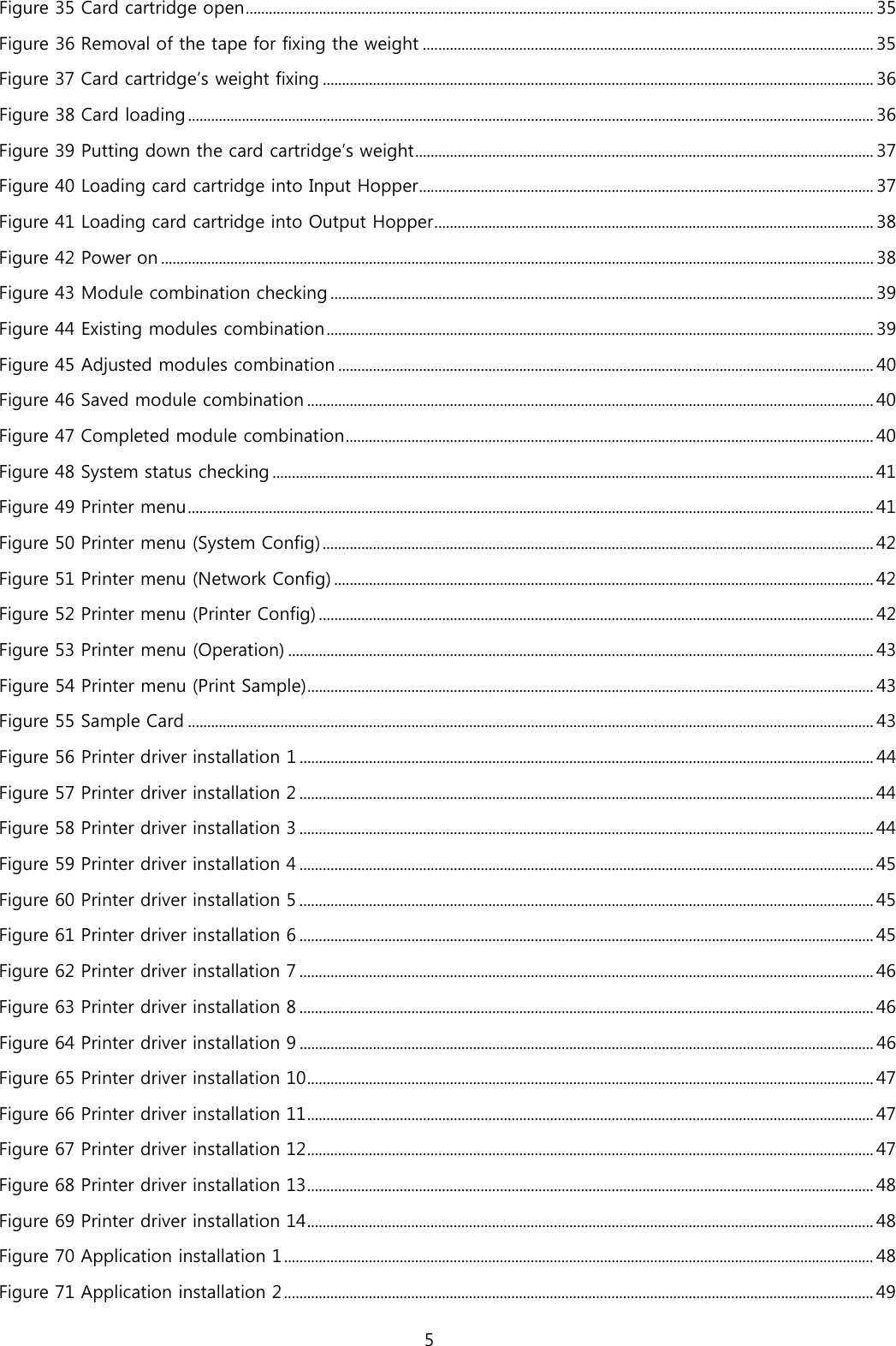
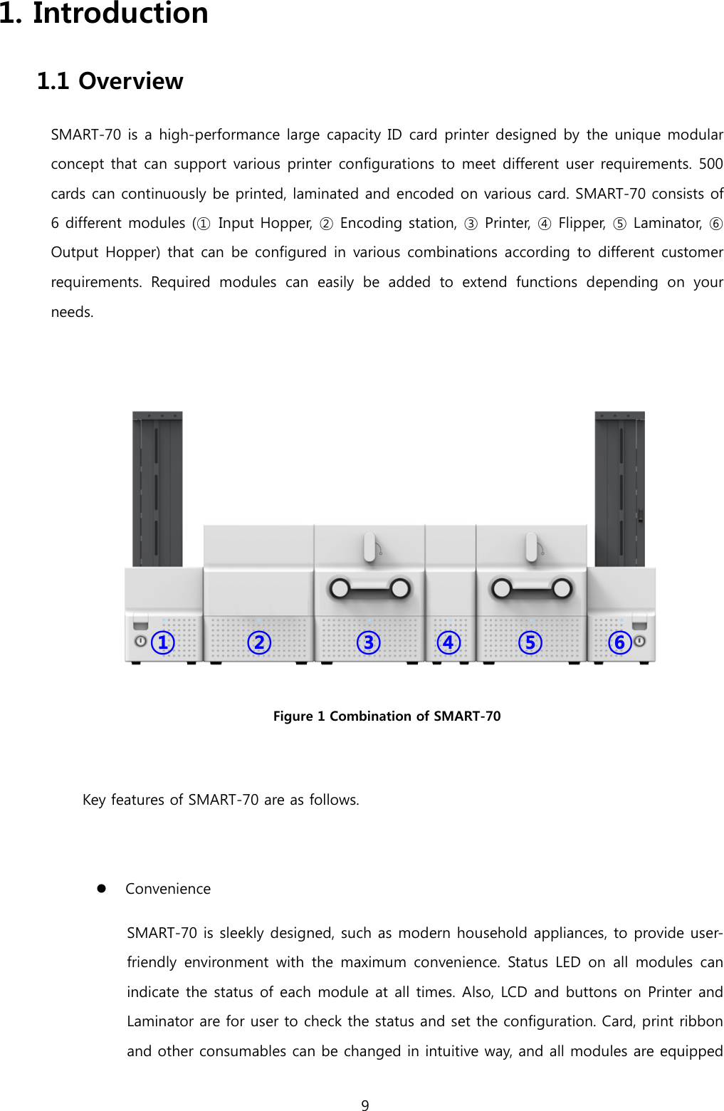
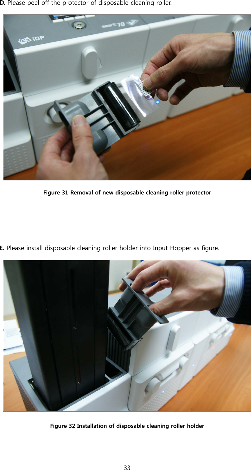
![E. On “Operation” menu, please press the [Select] button indicated by red arrow. Figure 53 Printer menu (Operation) F. On “Print Sample” menu, please press the [Select] button indicated by red arrow. Figure 54 Printer menu (Print Sample) G. Please wait a while until sample card is printed as figure. Figure 55 Sample Card 43](https://usermanual.wiki/IDP/SMART-70L.User-Manual-1/User-Guide-2870684-Page-43.png)