Contents
- 1. User Manual 1
- 2. User Manual 2
User Manual 2
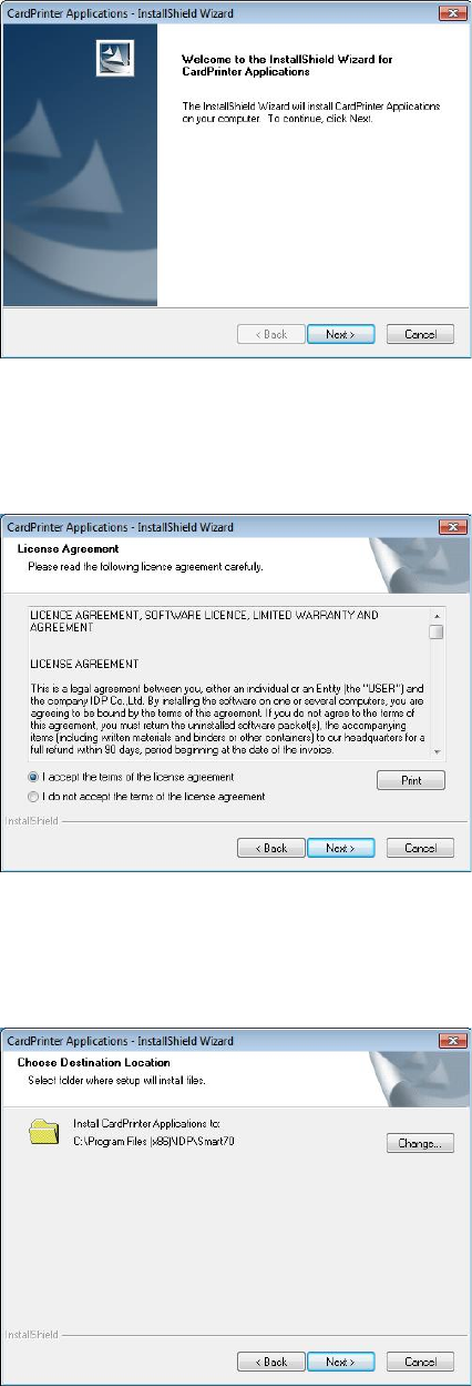
Figure 71 Application installation 2
2.2.16 Application installation 2
When “Smart Application Install Shield
Wizard”
window is opened, please click “Next”.
Figure 72 Application installation 3
2.2.17 Application installation 3
Please choose “I accept the terms of the license
agreement” and click “Next”.
Figure 73 Application installation 4
2.2.18 Application installation 4
Please select destination location for
application installation and click “Next”.
49
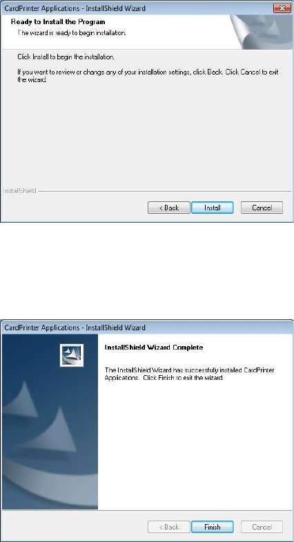
Figure 74 Application installation 5
2.2.19 Application installation 5
Please click “Install”.
Figure 75 Application installation 6
2.2.20 Application installation 6
After the application installation is completed,
please click “Finish” and use the installed
application.
50
3. Driver configuration
SMART-70 Printer can print cards by selecting various required properties. To adjust printer properties,
please open the Devices and Printers window and right click on “IDP SMART-70 Card Printer” and
select “Printer Properties”.
3.1 Printing preferences
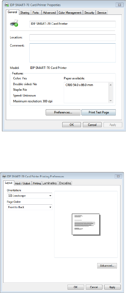
Figure 76 Printer properties window
3.1.1 Printing Preferences
Please click “Printing Preferences” on the
“General” tab of Printer Properties window.
Figure 77 Layout
3.1.2 Layout
The print orientation (Landscape or Portrait) can
be selected.
To apply your selection, please click “OK”.
51
3.1.3 Advanced setup
For Advanced setup, please click the “Advanced” button on “Printing Preferences” window and you
can adjust the advanced setting.
Reset Default Values: Advanced setting is reset to the default values.
Color Correction: Adjusting gamma value of each color panel can change color sense. The
higher gamma value is the darker color. The absolute printing density can be adjusted by using
“CardPrinter70Setup” utility.
- Main [-100:100]: To adjust the gamma values of all panels.
- Yellow [-100:100]: To adjust the gamma value of the yellow panel.
- Magenta [-100:100]: To a djust the gamma value of the magenta panel.
- Cyan [-100:100]: To adjust the gamma value of the cyan panel.
- Black [-100:100]: To adjust the gamma value of the resin black panel.
- Overlay [-100:100]: To adjust the gamma value of the overlay panel.
Position Processing: The printing position between panels can be adjusted. If the value is
higher, the positions are more accurate but the color sense may be a little lower.
- Color [-32:32]: To a djust the printing position of the color panels (yellow, magenta and cyan).
- Mono [-32:32]: To a djust the printing position of the resin black panel.
- Overlay [-32:32]: To a djust the printing position of the overlay panel.
Resin Black (K) Processing: The method to extract the data to be printed by the resin black is
specified.
- Text [0:100]: To set the density criteria for extracting the text to be printed by the resin black.
- Dot [0:100]: To set density criteria for extracting the pixels to be printed by the resin black.
- Threshold [0:100]: To set density criteria for printing by the resin black when the dithering is
performed by using the Threshold.
- Dithering Degree [0:100]: To set sharpness when the dithering is performed by using the
Random.
- Resin Extraction: Method to extract the data for the resin black.
> Black object: Text, line, etc. Black objects are extracted.
> Black Text: Text is only extracted.
52
> Black Dots: All black dots are extracted.
> Not Use: No extraction.
Rewritable Controls: This property is only for rewritable printer.
- Erase Density [0:100]: To set the temperature to erase the contents on rewritable card.
Wait Option: This option can set the card’s waiting time at each encoding position when the
smart card is encoded without using SDK. One contactless smart card encoder can be installed
into SMART-70 Printer. One contactless and one contact smart card encoder can be installed
into SMART-70 Encoding Station.
When this option is set and the SDK is not used for encoding, the program which the smart
card is recognized and encoded within the specified waiting time must be developed by
yourself because the card is only waiting for a specified time at the encoding position.
- Wait at Internal Module Contactless Encoding Position [On/Off]: To set that the contactless
smart card is waiting at the contactless smart card encoding position in Printer.
- Wait at External Module Contactless Encoding Position [On/Off]: To set that the
contactless smart card is waiting at the contactless smart card encoding position in Encoding
Station.
- Wait at External Module Contact Encoding Position [On/Off]: To set that the contact smart
card is waiting at the contact smart card encoding position in Encoding Station.
> Card Side [Front/Back]: To set the direction of card when the card is waiting.
> Wait Position [-100:100]: To a djust the card position from the previous waiting position of
card to the left or the right (unit is 0.1mm).
> Wait Time [0:1000]: To set the waiting time of card (unit is a second).
53
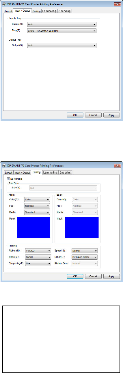
Figure 78 Input / Output settings
3.1.4 Input / Output settings
Supply Tray
Supply: If there is one Input Hopper,
please
select “Auto”. If there are multiple Input
Hoppers, please select the H
opper which
will be used.
Tray: Please select “CR80” because SMART-
70
only supports CR80 cards.
Output Tray
Output: If there is one
Output Hopper select
“Auto”. If there are multiple Output
Hoppers, please select the H
opper which
will be used.
Figure 79 Printing settings
3.1.5 Printing settings
Do Printing: To set whether print or not.
Print Side: To set the single sided or dual sided
printing when Flipper is installed.
Front / Back
Color: To set the color or mono printing.
Flip: To turn the printed image on card.
Mask: To set the printing area on card.
The
predefined mask
s (normal card, smartcard,
magnetic stripe card, etc.
) or user defined
mask cab be used.
Printing
Ribbon: The print
ribbon type is used for
printing and can be
automatically
recognized.
Speed: To set the printing speed.
Mode: To set the all or partial printing.
Dither: Set the dithering types.
Sharpening: To calibrate
the printed image
sharpness.
Ribbon Save:
To set that the card is printed
by using the split function when the mono
ribbon is used.
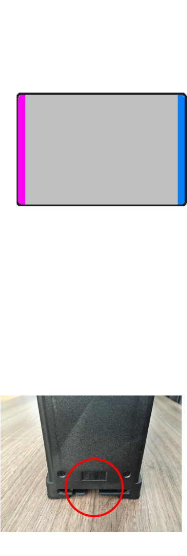
User defined mask uses BITMAP file (1012 x
636 pixels).
Blue(RGB(0,0,255)) : Print and Overlay
Light blue(RGB(0,255,255)) : Overlay only
Pink(RGB(255,0,255)) : Print only
Yellow(RGB(255,255,0)) : Florescent only
54
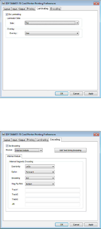
Figure 80 Laminating settings
3.1.6 Laminating settings
This tab will be created only when SMART-70
Laminator module is connected.
Do Laminating: To set whether laminate
or not.
Laminator Side:
To set the laminating side of
card (top, bottom and both sides).
Overlay: To set
whether overlay panel is
printed or not. Default is no overlay when
the
card is l
aminated. We recommend no overlay
when the card is laminated.
Figure 81 Encoding settings
3.1.7 Encoding settings
This tab will be created only when SMART-70
Magnetic Encoding option is installed.
Do Encoding: To set whether encoding or not.
Module: To set whether the internal module
(Printer) or the external module
(Encoding
Station) is used.
Coercivity: To set the type of the
magnetic
stripe cards for encoding.
LoCo: 300, 600 Oe.
HiCo: 2760 Oe.
SpCo: 4000 Oe.
Auto: Automatic encoding depending on a
used magnetic stripe card type.
Option: To set the encoding direction
(Forward / Backward / Bitmode).
Encoding: To set the encoding protocol
(ISO / Bally’s).
Mag Flip R/W: To set the encoding side of
magnetic stripe card.
55
3.2 Other settings
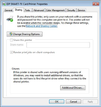
Figure 82 Printer sharing settings
3.2.1 Sharing
Printer can be shared via network by setting
the option of printer sharing on the Sharing
tab.
Default is “Not sharing”.
56
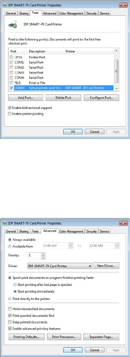
Figure 83 Ports setting
3.2.2 Ports
The Port tab shows which port is connected to
SMART-70 Printer. On Figure,
USB001 Virtual
printer port is connected because SMART-
70
Printer was connected via USB.
(C
aution! The adjustment on the ports setting
by user is not recommended because the port
is automatically set.)
Figure 84 Advanced settings
3.2.3 Advanced
The working time, priority order, spool and etc.
can be set in “Advanced” tab. The Advanced
setting follows MS Windows standard. If you
want to change the setting, please refer to the
MS Windows manual.
(No adjustment on the Advanced setting is
recommended.)
57
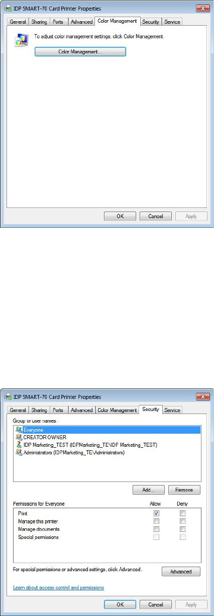
Figure 85 Color Management settings
3.2.4 Color Management
The proper color profile for Printer can be set
on the Color Management tab. For supporting
the optimized color printing, SMART-70 Printer
can automatically set the color profile
depending on the ribbon type loaded in Printer
because the ribbon type is automatically
recognized.
(
No adjustment on the Color Management
setting is recommended.)
Figure 86 Security setting
3.2.5 Security
The access control and permissions for Printer
can be set. According to the authority,
the
printing,
management and special authority can
be permitted.
58
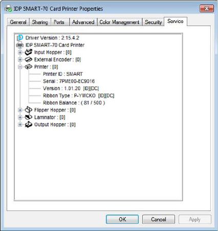
Figure 87 Printer status check
3.2.6 Printer status check
The serial number, ID, driver version, firmware
version, ribbon type and balance of all
connected modules can be checked on the
Service tab.
4. SMART-70 Utilities
The installation CD of SMART-70 Printer includes utilities for printer setting, test and firmware upgrade.
This chapter explains the SMART-70 utilities.
4.1 Printer setting
SMART-70 Printer is manufactured and shipped with optimized setting on each one. By the way,
printer setting can be adjusted by using CardPrinter70Setup utility included in the Installation CD
after disassemble and assemble of printer, replacement of some parts or when the adjustment of
printer setting is needed. Printer setting can be adjusted by using CardPrinter70Setup as below.
4.1.1 CardPrinter70Setup
59
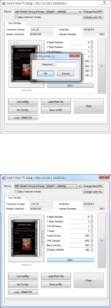
Figure 88 CardPrinter70Setup Log-in
Password input window is displayed when you run
this program. If
the correct password is inputted,
the
recorded setup values in SMART-
70 Printer are
shown and the
setup values can be adjusted.
The password
for SMART-70 Printer is saved to
the
SMART-70 Printer. When the SMART-70
Printer is connected to another PC
, the saved
password in the SMART
-70 Printer is required to
run this utility and adjust the Printer setting
.
(Since t
here is no default password in SMART-70
Printer, p
lease click “OK” if password have never
been set
.)
Figure 89 CardPrinter70Setup Start
When you
are successful to login, the basic setup
of Printer
is shown as Figure 89.
4.1.2 Basic Setup
The basic setup of CardPrinter70Setup shows the firmware version, serial number and etc. of
the connected SMART-70 Printer, frequently used setting values (printing position, density and
etc.) can be adjusted.
60
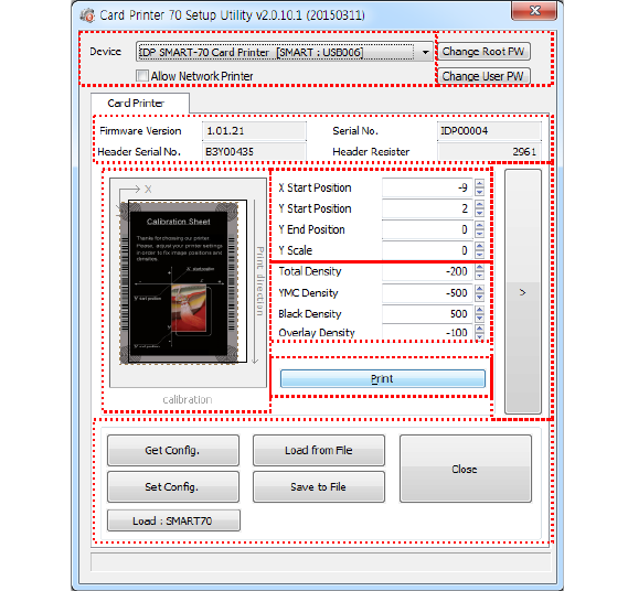
Figure 90 Basic Setup of CardPrinter70Setup
① To show connected Printer.
Device:
The Printer that the adjustment is needed can be selected by using the pull-down
menu. “IDP SMART-70 Card Printer” is the connected Printer’s name. “SMART” is the
connected Printer’s ID, “USB006” is the connected port.
Allow Network Printer:
If the Allow Network Card Printer is selected, Printers connected via
network also appear in the “Device” list.
② To set administrator password and user password.
Change Root PW:
To set administrator (root) password. This password is used to verify user
authority for CardPrinter70Setup and is also required as administrator password when the
User Authentication option on Security is set on advanced setup.
(When Printer is installed at the place where security is required, please set password at the
same time with the installation of Printer.)
Change User PW:
To set user password for user authentication. This password is required
as user password when the User Authentication option on Security is set on advanced
setup.
③ The firmware version, serial number of Printer, serial number of TPH, resistance value of
TPH, type of TPH is shown.
④ The printing area on card is shown. It shows exaggeratingly for user convenience and is not
real position.
⑤ To set the printing area on card. Please set it properly to print on an entire card because
SMART-70 is a direct thermal card printer. When you click “⑦ Print”, a card is printed as
like “④ example”. Please set values properly that all circles of each corner are printed and
①
②
③
④
⑤
⑥
⑦
⑧
⑨
61
blank spaces are narrower than 0.5mm on the top and the bottom of a card. Please set
values by following order.
X Start Position:
Please set the right and the left of printing position on card properly by
adjusting X position.
Y Start Position:
Please set the start position of printed example image and blank space in
the top is 0.4mm ~ 0.5mm.
Y End Position:
Please set the end position of printed example image and blank space in
the bottom is 0.4mm ~ 0.5mm. It is recommended to set bigger value for “Y scale” than
default.
Y Scale:
Please set to print all circles in the bottom of card.
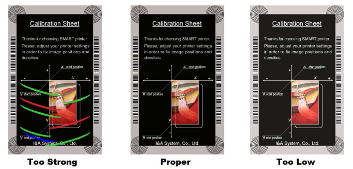
⑥ To set printed density. SMART-70 enables to set different density for each color, resin
black and overlay. So, proper setting on each density is needed for high quality. Please
optimize the quality by adjusting each value. To optimize, you repeatedly adjust the density
and print a Calibration card by using color ribbon and clicking “⑦ Print”, and please check
the printed state until you get the optimum.
Total Density:
To set all of the density (Color, Black and Overlay) at one time.
YMC Density:
To set color density. Please maximize YMC density as you can, which enables
to extend range of color and to print vivid images. If it is too strong, green or red marks are
appeared as Figure 91. If it is too weak, the print quality will be dull.
Figure 91 Color density
Black Density:
To Set resin black density. In the picture, barcode is printed by resin black.
When density is too strong, barcode is printed too thick. When density is too weak, barcode is
too thin. Please adjust resin black density to print clear barcode. Please refer following
pictures.
62
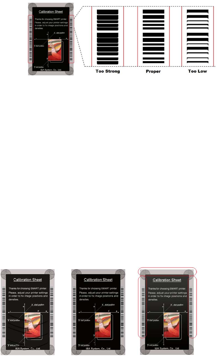
Figure 92 Resin Black density
Overlay Density:
To set overlay density. Please adjust it until overlay is printed on surface
regularly. If it is too strong, it is hazy and marks are appeared. If it is too weak, overlay panel
is not printed edge areas. You can check it with printed card under the light.
Too Strong Proper Too Low
Figure 93 Overlay density
⑦ To print calibration card for adjusting the printing position and density.
63
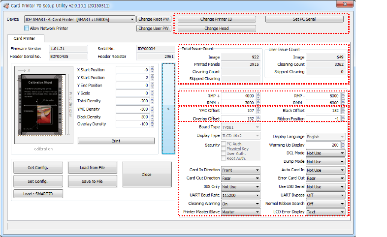
⑧ To show advanced setup.
(The advanced setup for expert options is not recommended to adjust.)
⑨ To load or save the setup values.
Get Config.:
To get values from current connected Printer.
Set Config.:
To set values to current connected Printer.
Load from File:
To load setup values from file.
Save to File:
To save setup values to file.
Load Default:
To reset setup values to default. After loading default, all setup values must
be adjusted again. Load Default is not recommended.
Close:
To close CardPrinter70Setup.
4.1.2 Advanced Setup
Expert setup of SMART-70 Printer can be adjusted on advance setup. If you are unsure, please
contact your dealer.
①
②
③
⑤
④
64
Figure 94 Advanced Setup
① To set Printer ID, PC Serial and Print Head register after replacing.
Change Printer ID: When SMART-70 is used by SDK, unique ID for SMART-70 Printer is set
regardless of whether it is connected via USB or what IP address is. It is useful to connect and
use several Printers. Factory default is “SMART”.
Set PC Serial: One of security functions. This function can be only used when Printer is
connected via USB and the Printer can be used with a specific PC. It is activated when “Set
PC Serial” is clicked after “PC Authentication” of ⑤ Security is set and rebooted. At that
time, the specific information of connected PC is saved to SMART-70 Printer and the saved
information is used to authenticate the connected PC.
Change Header: When thermal print head is replaced, the print head information must be
registered for optimal printing quality. Please change print head’s serial number, resistance
value and type in the Change Head Dialog window after click “Change Head”.
To show how many cards are issued with SMART-70 Printer. “Total Issue Count” is the number
of issued cards after factory shipment. “User Issue Count” is the number of issued cards after
replacing print head. When the print head is replaced, please initialize the number by setting
“Reset User Issue Count” in the Change Head Dialog window after clicking “Change Head” of
①.
② SMART-70 Printer controls motor for the best printing quality. “RMP+”, “RMP-“, “RMM+” and
“RMM-“ is necessary variables to control ribbon motor. Please do not adjust the variables
because the printing quality is affected.
When the normal printing speed is set, “YMC Offset”, “Black Offset” and “Overlay Offset” is
added to the YMC Density, Black Density and Overlay Density and printed on card. “Ribbon
Position” is to align the panel of ribbon on the card. Please use the default setting.
③ Please refer as below for other values.
Board Type: To set the mainboard type of SMART-70 Printer. Please do not change.
Display Type: To set the LCD type of SMART-70 Printer. Please do not change.
Display Language: To select the display language on the LCD of SMART-70 Printer. Please do
not change.
Security: SMART-70 Printer provides several ways to set a security function for authentication
and access control.
PC Auth.: Printer can only be used with specific PC. To activate this option, “Set PC Serial” is
clicked to save the specific PC’s information into Printer.
Physical Key: When physical key is installed into SMART-70, this option can set to activate
Printer by using the key.
User/Root Authentication: This option can set to activate Printer by using User and
65
Administrator (Root) password.
DCL Mode: When SDK is used to print cards with DCL mode, printer driver doesn’t need to
be installed. If the DCL mode is set to “Use”, printer driver is not installed on Windows.
Dump Mode: Log data can be recorded into Printer.
Card In Direction: To set the direction that card is fed.
Auto Card In: When the card is detected at card gate, the card is automatically moved into
Printer.
Card Out Direction: To set the direction that card is ejected.
Error Card Out: To set the direction which error card (encoding failed card) is ejected.
SBS Only: This option is only activated when SDK is used to print card. Printer driver can’t be
used when this option is set.
Use USB Serial: When SMART-70 Printer is connected to USB, Printer transmits the USB serial
number to PC. Default is the same number used by all SMART-70. To connect multiple
SMART-70 Printers to only one PC via USB, Please set this option to “USE” for using unique
serial numbers for each Printer.
UART Baud Rate: To set the communication speed (Baud rate) of the external device
connected to Printer by serial.
UART Bypass: When Printer is communicated with an external device by serial interface, the
commands are passed without any processing.
Cleaning Warning: After a certain number of printings, Printer is contaminated and needed
to clean for keeping the Printer in the best condition. If cleaning is required, please set how
to display the warning message.
Normal Ribbon Search: To set that SMART-70 can search the panel of ribbon more
accurately in ribbon searching.
Printer Master/Slave: SMART-70 Printer can variously be configured according to your needs
and two Printers can be connected and used. In this case, this option is used to set the
Printer connected to PC via USB to “MASTER” and set the other Printer to “SLAVE”.
LCD Error Display: To set the displayed message type on the LCD of Printer when error
occurs in Printer.
66
4.2 Printer test
Since card printer basically use standard printer device driver, card can be printed by the same
method as a general paper printer. By the way, if encoding options are installed into card printer,
appropriate device driver for each encoding option must be installed and each encoding option
must be properly operated. In this case, encoding options can be controlled by “Card Printer SDK”.
CardPrinter70Test utility is to test the functions of SMART-70 Printer and is developed by “SMART-
70 Printer SDK”.
67
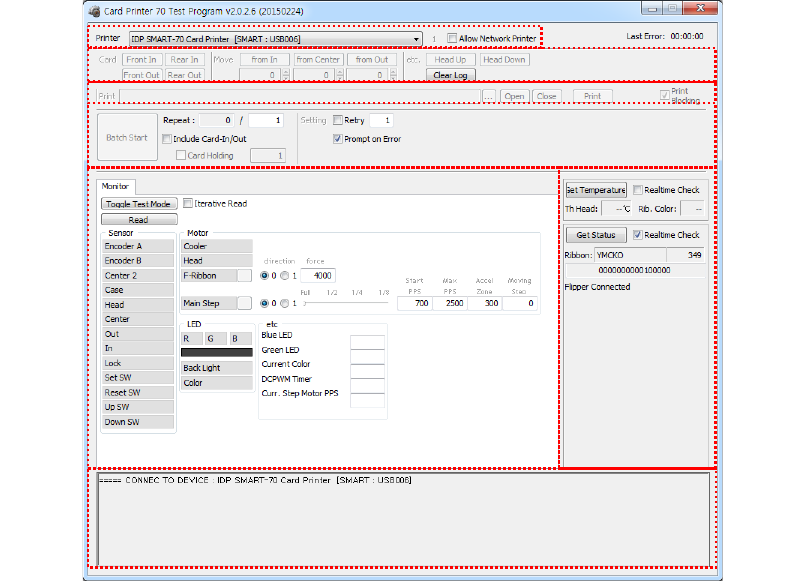
Figure 95 CardPrinter70Test
① Select Printer: To select a Printer for test. In the picture. “IDP SMART-70 Card Printer” is the
connected Printer’s name, “SMART” is the connected Printer’s ID and “USB006” is the
connected port.
② Basic Control: To execute basic functions of Printer (Card In/Out, Print Head Up/Down, etc.).
③ Print: To pri n t a CSD file which is designed by SMART Design.
④ Batch Job: To execute the job of ⑤ repeatedly.
⑤ Monitor: To check the working status of sensors and motors.
⑥ Printer Status: To check the status of Printer.
⑦ Message: To display messages when this utility is run.
4.2.1 Printer selection and basic control
When CardPrinter70Test is run, Printers connected via USB are automatically searched and can be
selected by priority. After setting "Allow Network Printer", all Printers connected via USB and
network can be selected. Other Printer can be selected by using pull-down menu. When a printer
is connected to this utility, the basic control, print and monitor can be tested.
The basic control functions will be provided later.
①
③
④
⑤
⑦
②
⑥
68
4.2.2 Print Test
Print is to print a CSD file designed by SMART Design. This function will be provided later.
4.2.3 Batch Job
Batch job is to test the status of encoding and decoding continuously. This function will be
provided later.
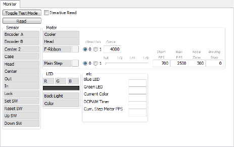
4.2.4 Monitor
Monitor is to check the status of Printer in the “Monitor” tab.
Toggle Test Mode: To switch between normal mode and board test mode.
Read: To read the status of sensors and motors from Printer.
Iterative Read: When the “Iterative Read” is set, the status of sensors and motors is periodically
read from Printer.
Figure 96 Monitor
4.2.5 Printer status
“Get Temperature” is to get and display the temperature of Thermal Print Head. When the
“Realtime Check” is set, the temperature of Thermal Print Head is got and displayed in real time.
“Get Status” is to get and display the status of Printer.
Status Codes are as below.
#define S7PS_M_SBSRUNNING 0x0000000000000001 // SBS (Step by Step) command execution
69
#define S7PS_M_CARDMOVE 0x0000000000000002 // Move to print
#define S7PS_M_CARDIN 0x0000000000000004 // Card In
#define S7PS_M_CARDOUT 0x0000000000000008 // Card Out
#define S7PS_M_THEAD 0x0000000000000010 // Thermal Head Up/Down
#define S7PS_M_SEEKRIBBON 0x0000000000000020 // Ribbon Search
#define S7PS_M_MOVERIBBON 0x0000000000000040 // Ribbon Move
#define S7PS_M_PRINT 0x0000000000000080 // Printing
#define S7PS_M_MAGRW 0x0000000000000100 // Magnetic Read/Write
#define S7PS_M_RECVPRINTDATA 0x0000000000000200 // Printing data Receiving
#define S7PS_M_INIT 0x0000000000000400 // Initializing
#define S7PS_S_INSTALLINTENCODER 0x0000000000008000 // Internal Encoder Installed
#define S7PS_S_INSTALLEXTHOPPER 0x0000000000010000 // External Input Hopper Installed
#define S7PS_S_INSTALLEXTSTACKER 0x0000000000020000 // External Output Hopper Installed
#define S7PS_S_INSTALLEXTENCODER 0x0000000000040000 // External Encoder Installed
#define S7PS_S_INSTALLEXTLAMINATOR 0x0000000000080000 // External Laminator Installed
#define S7PS_S_INSTALLEXTFLIPPER 0x0000000000100000 // External Flipper Installed
#define S7PS_S_INSTALLEXTETC 0x0000000000200000 // External Other Device Installed
#define S7PS_S_CASEOPEN 0x0000000000400000 // Case Open
#define S7PS_S_SOFTLOCKED 0x0000000000800000 // Soft Locked
#define S7PS_S_KEYLOCKED 0x0000000001000000 // Key Locked
#define S7PS_S_DETECTCARD 0x0000000002000000 // Card Detected Internal Sensor
#define S7PS_S_DETECTFRONTDEVICE 0x0000000004000000 // Front Device Detected
#define S7PS_S_DETECTREARDEVICE 0x0000000008000000 // Rear Device Detected
#define S7PS_S_CLEANWARNING 0x0000000010000000 // Printer Cleaning Warning
#define S7PS_S_HAVEPRINTDATA 0x0000000020000000 // Have Printing Data
#define S7PS_S_SBSMODE 0x0000000040000000 // SBS Mode
#define S7PS_S_TESTMODE 0x0000000080000000 // Test Mode
Error Codes are as below.
#define S7PS_E_CARDIN 0x0000000100000000 // Card In Error
#define S7PS_E_CARDMOVE 0x0000000200000000 // Card Move Error
70
#define S7PS_E_CARDOUT 0x0000000400000000 // Card Out Error
#define S7PS_E_THEADLIFT 0x0000000800000000 // Thermal Head Up/Down Error
#define S7PS_E_PRINT 0x0000004000000000 // Printing Error
#define S7PS_E_MAGRW 0x0000008000000000 // (Internal) Magnetic Read/Write Error
#define S7PS_E_MAGREADT1 0x0000010000000000 // (Internal) Mag. Track 1 Read Error
#define S7PS_E_MAGREADT2 0x0000020000000000 // (Internal) Mag. Track 2 Read Error
#define S7PS_E_MAGREADT3 0x0000040000000000 // (Internal) Mag. Track 3 Read Error
#define S7PS_E_CONNECTEXTHOPPER 0x0000080000000000 // External Hopper Connection Error
#define S7PS_E_CONNECTEXTSTACKER 0x0000100000000000 // External Stacker Connection Error
#define S7PS_E_CONNECTEXTENCODER 0x0000200000000000 // External Encoder Connection Error
#define S7PS_E_CONNECTEXTLAMINATOR 0x0000400000000000 // External Laminator Connection Error
#define S7PS_E_CONNECTEXTFLIPPER 0x0000800000000000 // External Flipper Connection Error
#define S7PS_E_CONNECTEXTETC 0x0001000000000000 // External Other Device Connection Error
#define S7PS_E_EXTPRESETMATCH 0x0002000000000000 // External Preset Device Connection Error
#define S7PS_E_RIBBONSEEK 0x0080000000000000 // Ribbon Search Error
#define S7PS_E_RIBBONMOVE 0x0100000000000000 // Ribbon Move Error
#define S7PS_F_THEADABSENT 0x0200000000000000 // Uninstalled Thermal Head
#define S7PS_F_THEADOVERHEAT 0x0400000000000000 // Overheat Thermal Head
#define S7PS_F_RIBBONABSENT 0x0800000000000000 // No Ribbon
#define S7PS_F_PRINTDATA 0x1000000000000000 // Printing Data Error
#define S7PS_F_INCORRECTPASSWORRD 0x2000000000000000 // Incorrect Password
#define S7PS_F_CONFIG 0x4000000000000000 // Configuration Fail
4.3 Firmware upgrade
SMART-70 Modules’ firmware can be updated by using CardPrinter70Firmware. Since SMART-70 is
operated by combined several modules, firmware of each module can be individually upgraded as
necessary.
When CardPrinter70Firmware is run, the window as below is shown.
71
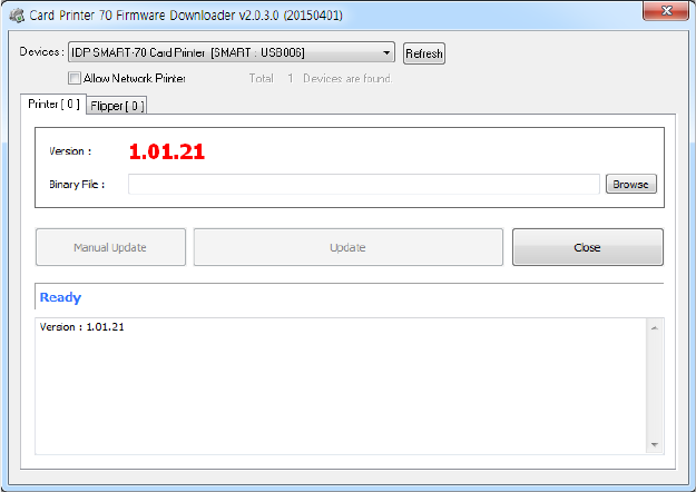
Figure 97 CardPrinter70Firmware
Devices: To select the Printer that firmware will be upgraded.
Allow Network Printer: To set that Printers connected via network are displayed in Devices.
Printer [ 0 ] / … : To select the modules of SMART-70 system that firmware is upgraded.
Version: To displays the current firmware version of selected Printer.
Binary File: To select the new firmware file. Please click “Browse” button to search and select
the new firmware file.
Manual Update: To upgrade the firmware manually.
Update: To upgrade the firmware automatically. Update for automatic upgrading is generally
recommended.
Close: To close this utility.
Message: Necessary information is displayed when the firmware is being upgraded.
4.3.1 Printer connection
After SMART-70 Printer is connected to PC and the connected Printer is selected on Devices of
CardPrinter70Firmware, all modules of SMART-70 System are displayed as tabs.
SMART-70 System is combined by "Printer module 0" and "Flipper module 0" as Figure.
72
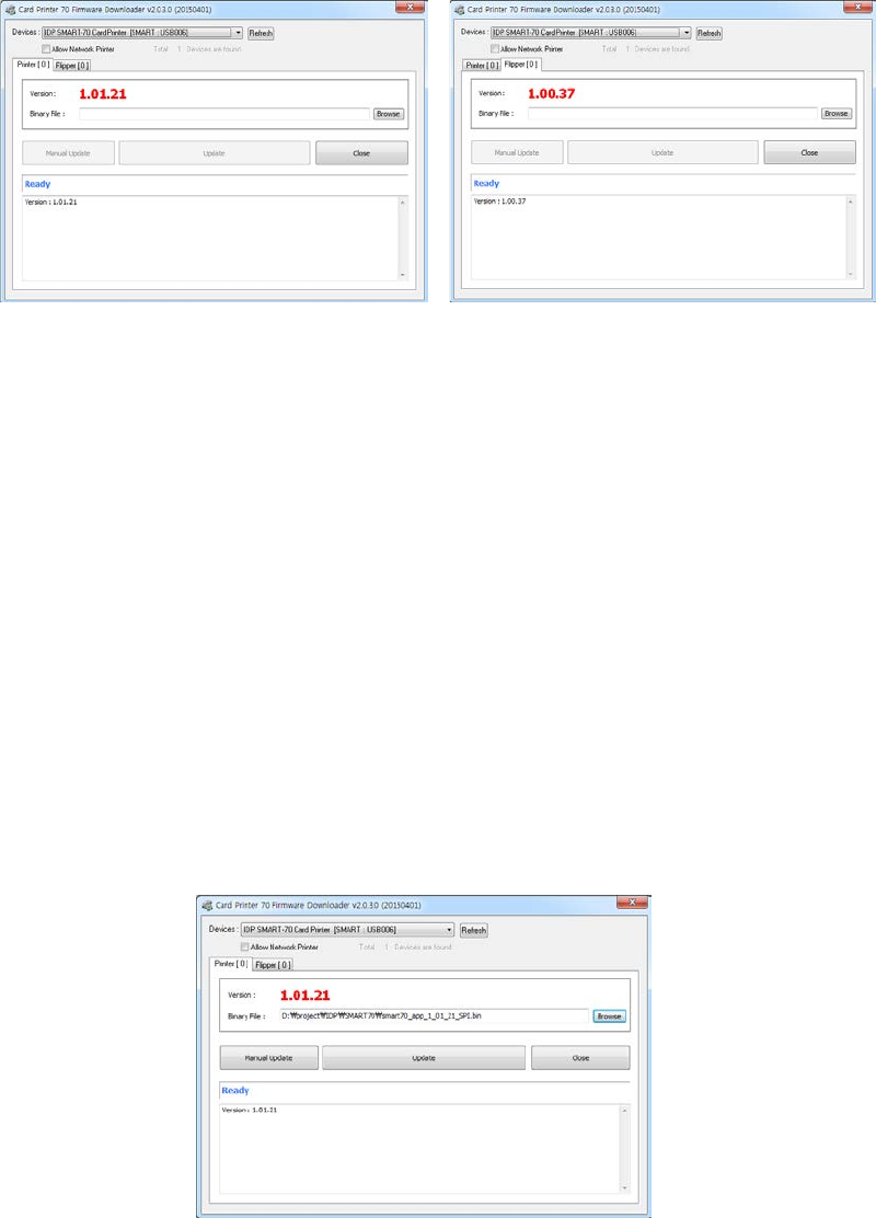
Figure 98 Modules of SMART-70 System (Printer, Flipper)
4.3.2 Module Firmware Upgrade
After clicking the tab of the combined modules of SMART-70 System such as “Printer [ 0 ]” or
Flipper [ 0 ]”, please click “Browse” and search and select the new firmware for the module. After
selecting the new firmware, “Manual Update” and “Update” is activated. Please click “Update” for
automatic firmware upgrade, and the Printer is automatically rebooted after firmware upgrade.
(Caution. Please do not do another job until the firmware upgrade is successfully completed and
do not turn off the Printer.)
Figure 99 Ready for firmware upgrade
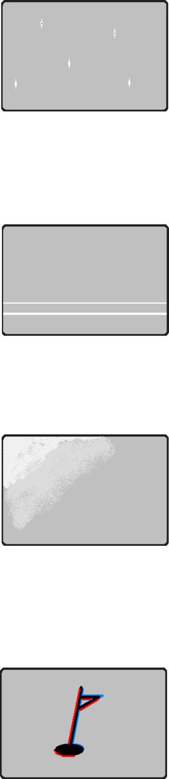
In case there is some problems in automatic firmware upgrade, please click “Manual Update” to
manually upgrade firmware. According to the pop-up window as below figure, firmware can
manually be upgraded by clicking “Transfer” after the Printer is manually turned on and off.
73
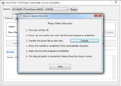
Figure 100 Manual firmware upgrade
5. Troubleshooting
5.1 Printing quality
74
5.1.1 Unprinted or wrong colors printed spot
The card surface is contaminated by foreign substance.
After checking the status of card, please change it
to another clean card.
The cleaning roller is contaminated.
After checking the cleaning roller. If the cleaning roller
is contaminated too much, please change a disposable
cleaning roller.
Dust is too much in printer.
Please clean the inside of printer by using cleaning kit.
5.1.2 Unprinted horizontal line
The print head is contaminated by foreign substance.
Please clean the print head by using cleaning kit.
The print head is damaged.
Please contact the local supplier to replace the print head.
The ribbon cartridge is improperly installed.
Please check the installation status of ribbon cartridge
and whether the print ribbon has wrinkles.
5.1.3 Blurry or unstable print
Uneven or bad surface of card.
Please change cards.
Too high or too low setting of color density.
The printing density of your printer must be adjusted.
Please contact the local supplier.
The print head is contaminated by foreign substance.
Please clean the print head by using cleaning kit.
5.1.4 Not aligned color print
Non-standard or bad cards.
Please change cards
(ISO CR80 card (54mm x 86mm) must be used).
Figure 102 Printing quality trouble 2
Figure 103 Printing quality trouble 3
Figure 101 Printing quality trouble 1
75
Uneven or bad surface of card.
Please change cards.
Card feeding or printing roller is contaminated.
Please clean the rollers by using cleaning kit.
Outdated printer.
Please contact the local supplier.
5.1.5 Unplanned color print
Non-standard or bad cards.
Please change cards
(ISO CR80 card (54mm x 86mm) must be used).
Card feeding or printing roller is contaminated.
Please clean the rollers by using cleaning kit.
Malfunctioned ribbon sensors.
Please contact the local supplier to replace the sensors.
Outdated printer.
Please contact the local supplier.
5.2 Card supply
5.2.1 Card is not supplied or 2 cards are supplied from Input Hopper
Non-standard or bad cards.
Please change cards
(ISO CR80 card (54mm x 86mm) must be used).
Card cartridge is improperly loaded.
Please properly load the card cartridge into
Input Hopper again.
Card thickness of card cartridge is improperly set.
Please properly adjust the card thickness control lever
depending on the thickness of card. In case card is not
supplied, please adjust the lever to the right.
In case 2 cards are supplied, please adjust the lever
to the left.
5.3 Card jam
5.3.1 Card jam in Input Hopper
Figure 104 Printing quality trouble 4
Figure 105 Printing quality trouble 5
Figure 106 Card supply problem 1
76
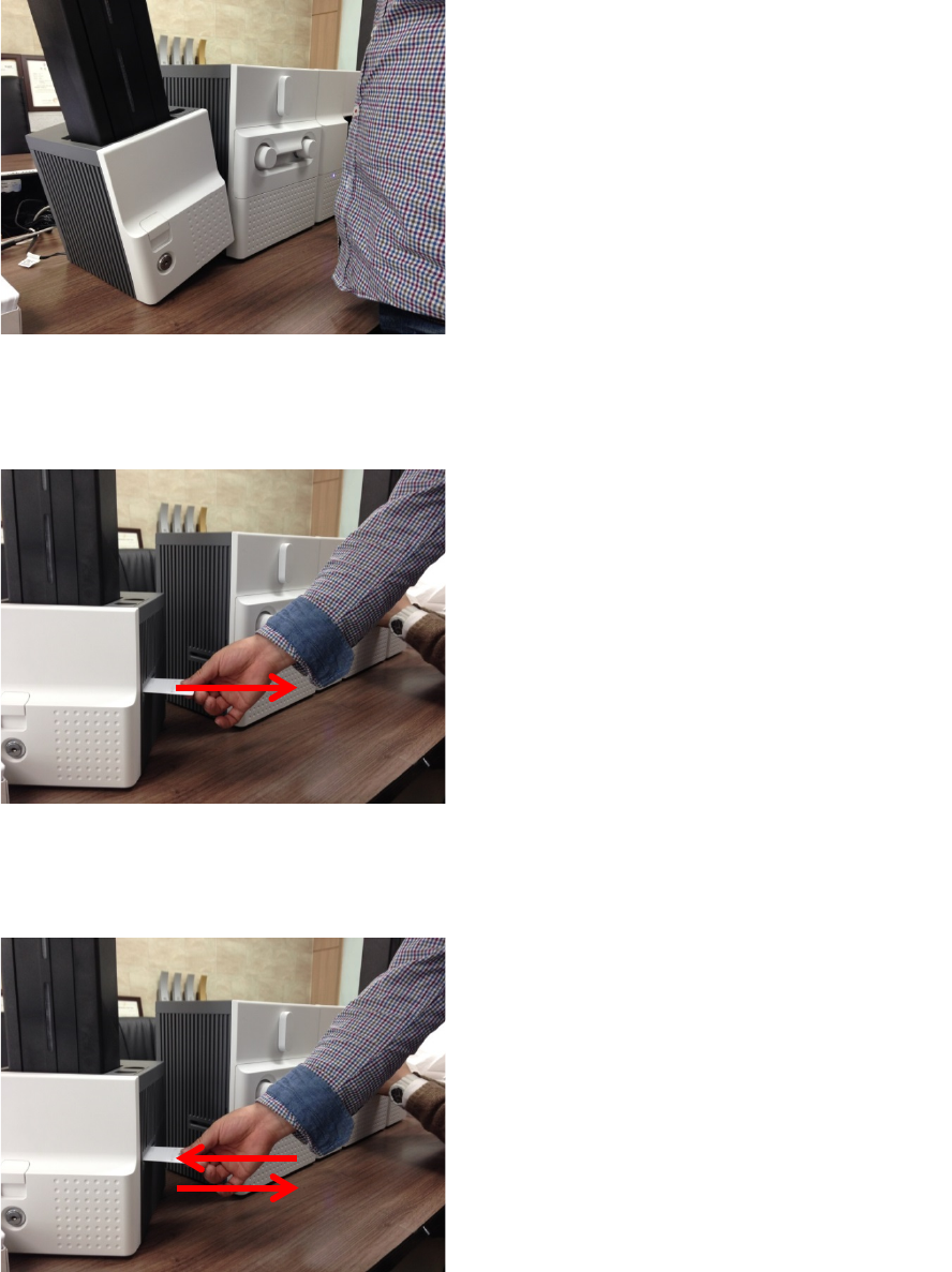
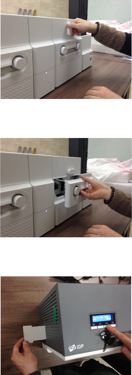
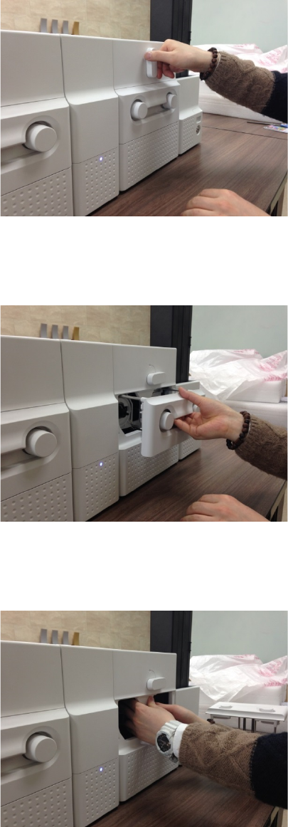
Figure 107 Card jam in Input Hopper 1
A. C
ard jam in Input Hopper 1
Please separate Input Hopper as Figure
after disconnecting power adaptor and
communication cable at rear side.
Figure 108 Card jam in Input Hopper 2
B. C
ard jam in Input Hopper 2
If card is jammed on the card gate of
Input Hopper as Figure, please remove the
jammed card by pulling out.
Figure 109 Card jam in Input Hopper 3
C. C
ard jam in Input Hopper 3
If card is not on the card gate of Input Hopper
but card cartridge can’t be pulled up, please
push in and pull out a new card as Figure.
77
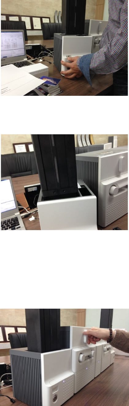
Figure 110 Card jam in Input Hopper 4
D. C
ard jam in Input Hopper 4
Please pull up card cartridge while pushing
the
cartridge release button as Figure.
Figure 111 Card jam in Input Hopper 5
E. C
ard jam in Input Hopper 5
If card
is jammed at the gate of card cartridge
as Figure, please remove the jammed card by
pulling out.
5.3.2 Card jam in Printer
Figure 112 Card jam in Printer 1
A. C
ard jam in Printer 1
Please turn the ribbon cartridge lock lever
to
the clockwise 90 degrees as Figure.
78
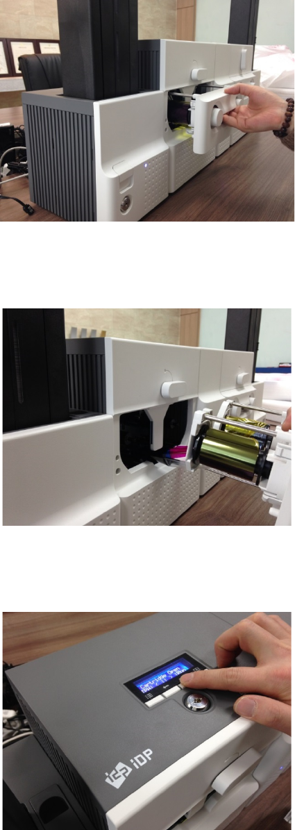
Figure 113 Card jam in Printer 2
B. C
ard jam in Printer 2
Please pull out the ribbon cartridge as Figure.
Figure 114 Card jam in Printer 3
C. C
ard jam in Printer 3
If print ribbon is stuck to card or coiled on
rollers as Figure, the ribbon cartridge may
not
be pulled out easily. In this case, please cut
the
ribbon or slowly pull out the
ribbon cartridge
while pressing the “” or “” button on
the
control panel of Printer little by little.
Figure 115 Card jam in Printer 4
D. C
ard jam in Printer 4
To remove a jammed card in Printer
, please
press the “” button
on the control panel of
Printer until
the jammed card is completely
ejected.
79
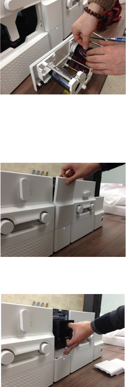
Figure 116 Card jam in Printer 5
E. C
ard jam in Printer 5
If print ribbon is cut, please stick the cut ribbon
together by using a sticky tape and
then turn
the dial on ribbon cartridge until unused panel
of ribbon is on take-up core.
5.3.3 Card jam in Flipper
Figure 117 Card jam in Flipper 1
A. C
ard jam in Flipper 1
Please open the cover of Flipper by pulling
as
Figure.
Figure 118 Card jam in Flipper 2
B. C
ard jam in Flipper 2
Please pull out the error card bin in Flipper
as
Figure.
80
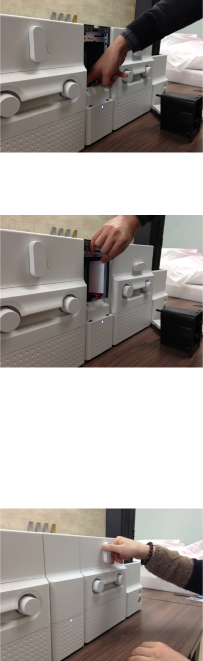
Figure 119 Card jam in Flipper 3
C. C
ard jam in Flipper 3
To remove a jammed card, please
turn the
rotating tray of Flipper until the vertical
by
hand as Figure.
Figure 120 Card jam in Flipper 4
D. C
ard jam in Flipper 4
Please pull out a jammed card as Figure.
5.3.4 Card jam in Laminator
Figure 121 Card jam in Laminator 1
A. C
ard jam in Laminator 1
Please turn the film cartridge
lock lever to the
clockwise 90 degrees as Figure.
81
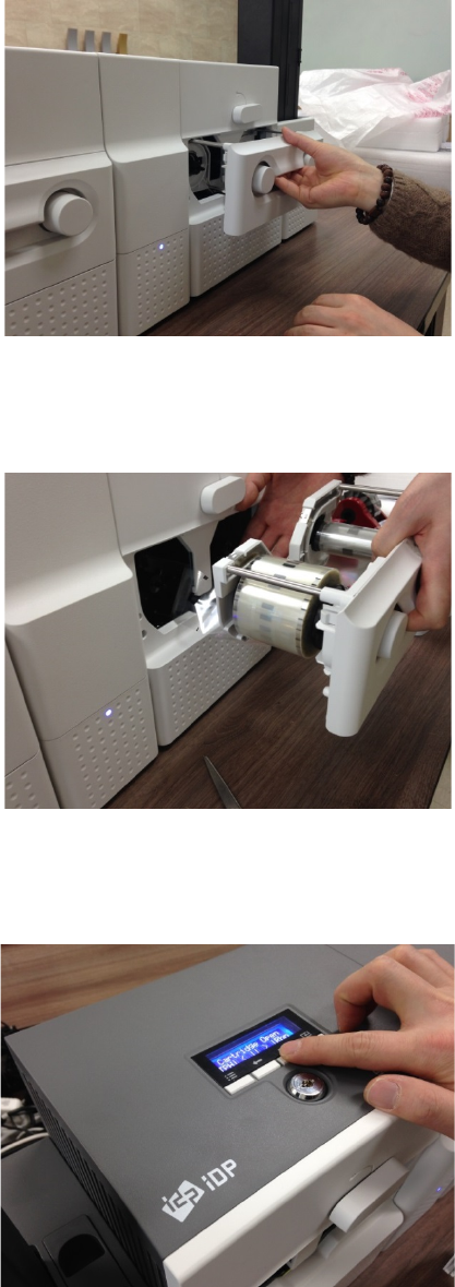
Figure 122 Card jam in Laminator 2
B. C
ard jam in Laminator 2
Please pull out the film cartridge as Figure.
Figure 123 Card jam in Laminator 3
C. C
ard jam in the Laminator 3
If laminating film is stuck to card or
coiled on
rollers as Figure, the film cartridge
may not be
pulled out easily. In this case, please cut
the
laminating film or slowly pull out the
film
cartridge while pressing the “” or “
” button
on the control panel of Laminator little by little.
Figure 124 Card jam in Laminator 4
D. C
ard jam in Laminator 4
To remove a jammed card in laminator
, please
press the “” button
on the control panel of
Laminator
until the jammed card is completely
ejected.
82
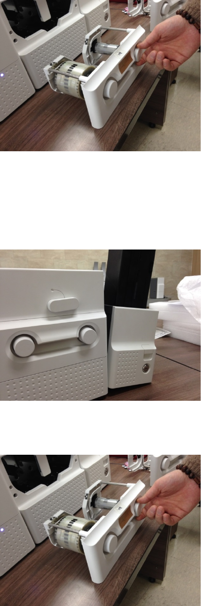
Figure 125 Card jam in Laminator 5
E. C
ard jam in Laminator 5
If laminating film
is cut, please stick the cut
laminating film
together by using a sticky tape
and then turn the dial on film cartridge
until
unused laminating film is on take-up core.
5.3.5 Card jam in Output Hopper
Figure 126 Card jam in Output Hopper 1
A. C
ard jam in Output Hopper 1
Please separate Output Hopper as Figure after
disconnecting power adaptor and
communication cable at rear side.
Figure 127 Card jam in Output Hopper 2
B. C
ard jam in Output Hopper 2
I
f card is jammed on the card gate of Output
Hopper as Figure, please remove the jammed
card by pulling out.
83
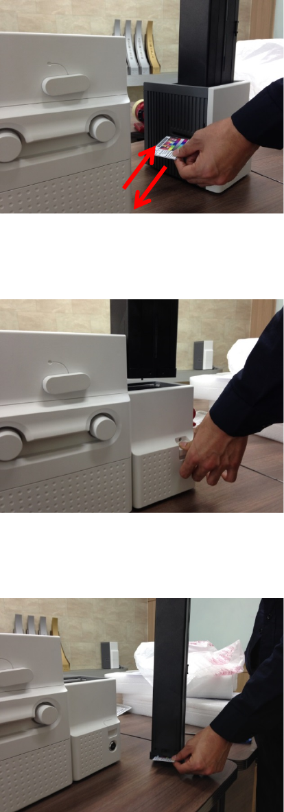
Figure 128 Card jam in Output Hopper 3
C. C
ard jam in Output Hopper 3
If card is not on the card gate
of Output
Hopper but card cartridge can
’t be pulled up,
please push in and pull out a new card as
Figure.
Figure 129 Card jam in Output Hopper 4
D. C
ard jam in Output Hopper 4
Please p
ull up card cartridge while pushing the
cartridge release button as Figure.
Figure 130 Card jam in Output Hopper 5
E. C
ard jam in Output Hopper 5
I
f card is jammed at the gate of card cartridge
as Figure, please
remove the jammed card by
pulling out.
84
5.4 Cleaning
5.4.1 Input Hopper cleaning
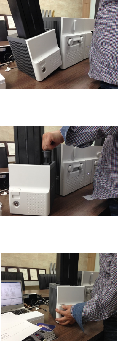
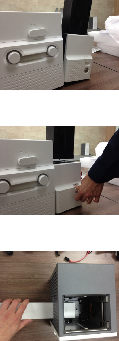
Figure 131 Input Hopper cleaning 1
A.
Input Hopper cleaning 1
Please separate Input Hopper as Figure after
disconnecting power adaptor and
communication cable at rear side.
Figure 132 Input Hopper cleaning 2
B.
Input Hopper cleaning 2
Please remove the disp
osable cleaning roller
holder in Input Hopper as Figure.
Figure 133 Input Hopper cleaning 3
C.
Input Hopper cleaning 3
Please pull up the card cartridge while pushing
the cartridge release button as Figure.
85
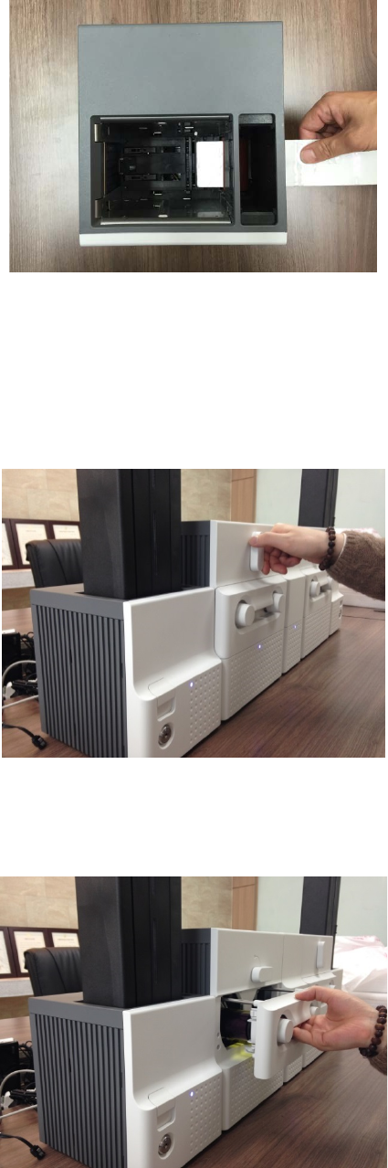
Figure 134 Input Hopper cleaning 4
D.
Input Hopper cleaning 4
Please push a cleaning card into the card gate
of Input Hopper as Figure and clean rollers
by
pushing in and pulling out the cleaning card
slowly and repeatedly.
5.4.2 Printer cleaning
Figure 135 Printer cleaning 1
A.
Printer cleaning 1
Please turn the ribbon cartridge lock lever
to
the clockwise 90 degrees as Figure.
Figure 136 Printer cleaning 2
B.
Printer cleaning 2
Please pull out the ribbon cartridge as Figure.
86
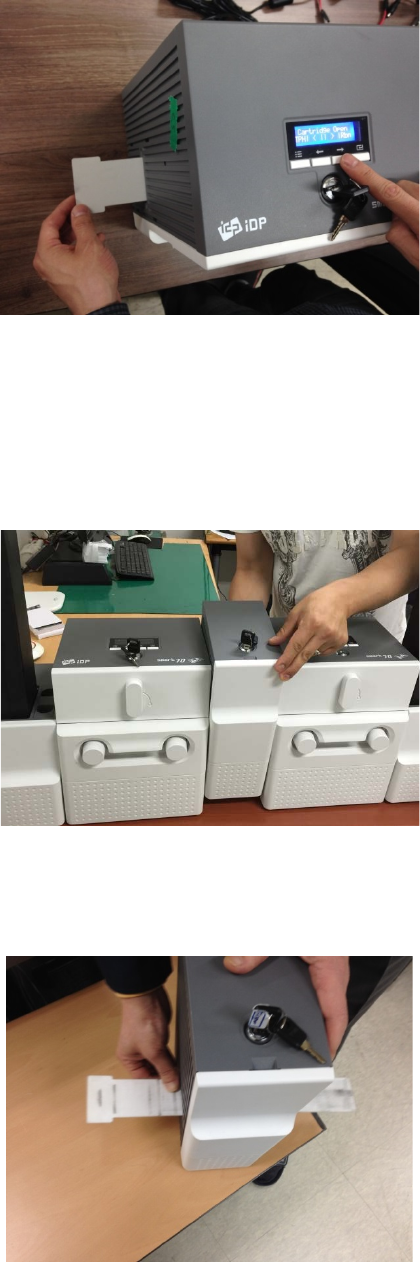
Figure 137 Printer cleaning 3
C.
Printer cleaning 3
Please push a cleaning card in Printer while
pressing the “” button on the control panel
of Printer for 30 seconds as Figure.
After cleaning, please press the “” button to
remove the cleaning card.
5.4.3 Flipper cleaning
Figure 138 Flipper cleaning 1
A.
Flipper cleaning 1
Please separate Flipper as Figure after
disconnecting power adaptor and
communication cable at rear side.
Figure 139 Flipper cleaning 2
B.
Flipper cleaning 2
Please push a cleaning card into the card gate
of Flipper until the cleaning card is shown at
the other side as Figure and clean rollers by
pushing in and pulling out the cleaning card
slowly and repeatedly
87
5.4.4 Laminator cleaning
Figure 140 Laminator cleaning 1
A.
Laminator cleaning 1
Please turn the film cartridge lock lever
to the
clockwise 90 degrees as Figure.
Figure 141 Laminator cleaning 2
B.
Laminator cleaning 2
Please pull out the film cartridge as Figure.
Figure 142 Laminator cleaning 3
C.
Laminator cleaning 3
Please push a cleaning card in Laminator while
pressing the “” button on the control panel
of Laminator for 30 seconds as Figure.
After cleaning, please press the “” button to
remove the cleaning card.
88
5.4.5 Output Hopper cleaning
Figure 143 Output Hopper cleaning 1
A.
Output Hopper cleaning 1
Please separate Output Hopper as Figure after
disconnecting power adaptor and
communication cable at rear side.
Figure 144 Output Hopper cleaning 2
B.
Output Hopper cleaning 2
P
lease pull up the card cartridge while pushing
the cartridge release button as Figure.
Figure 145 Output Hopper cleaning 3
C.
Output Hopper cleaning 3
Please push a cleaning card into the card gate
of Output Hopper as Figure and clean rollers
by pushing in and pulling out the cleaning card
slowly and repeatedly.
89
5.5 TPH (Thermal Print Head) replacement
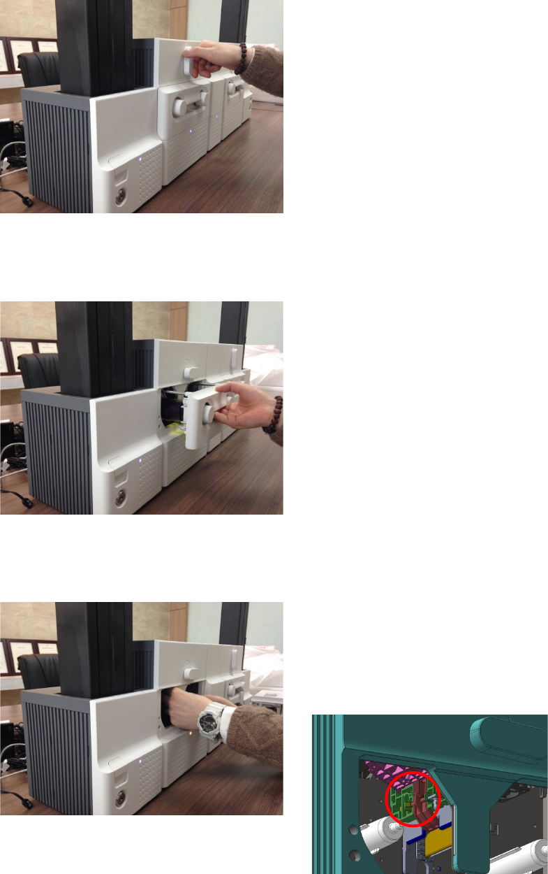
Figure 146 TPH replacement 1
A. T
PH replacement 1
Please turn the ribbon cartridge lock lever
of
Printer to the clockwise 90 degrees as Figure.
Figure 147 TPH replacement 2
B. T
PH replacement 2
Please pull out the ribbon cartridge as Figure.
Figure 148 TPH replacement 3
C. T
PH replacement 3
Please detach the print head while press
ing the
print head detaching button as Figure.
90
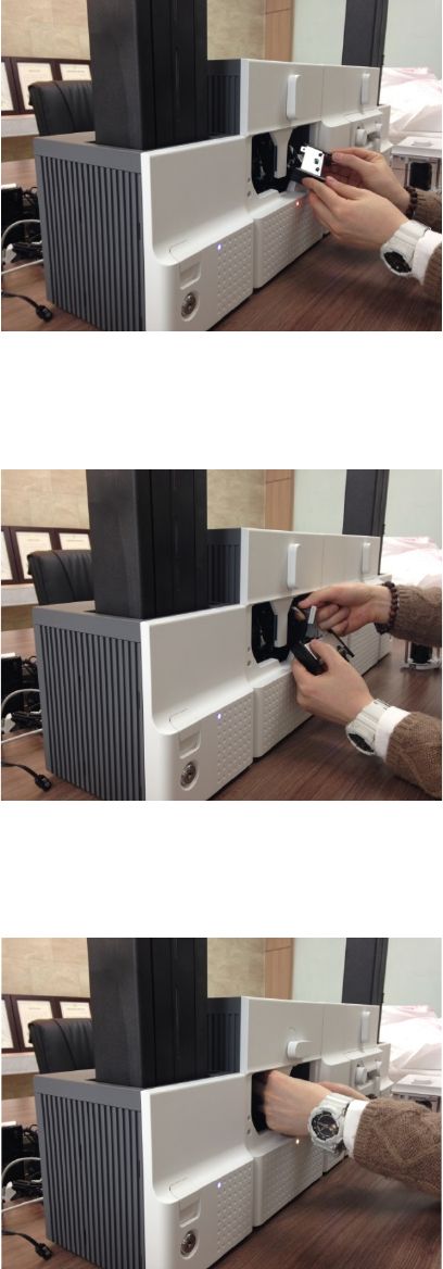
Figure 149 TPH replacement 4
D. T
PH replacement 4
Please pull
the detached print head out of
Printer while turning the ribbon cartridge
lock
lever to the counterclockwise 90 degrees
as
Figure.
Figure 150 TPH replacement 5
E. T
PH replacement 5
Please disconnect the print head cable from
the
detached print head as Figure and then
connect the print head cable to a
new print
head.
Figure 151 TPH replacement 6
F. T
PH replacement 6
Please install the new print head into
Printer
while turning the ribbon cartridge lock lever
to
the clockwise 90 degrees as Figure.
91
5.6 Laminator Head replacement
Figure 152 Laminator Head replacement 1
A. L
aminator Head replacement 1
Please turn the film cartridge lock lever
to the
clockwise 90 degrees as Figure.
Figure 153 Laminator Head replacement 2
B. L
aminator Head replacement 2
Please pull out the film cartridge as figure.
Figure 154 Laminator Head replacement 3
C. L
aminator Head replacement 3
Please detach the laminate head w
hile pressing
the laminate head detaching button as Figure.
92
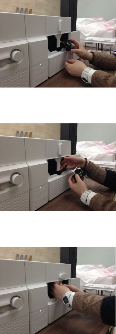
Figure 155 Laminator Head replacement 4
D. L
aminator Head replacement 4
Please pull the detached laminate head out of
Laminator while turning the film cartridge
lock
lever to the counterclockwise 90 degrees as
Figure.
Figure 156 Laminator Head replacement 5
E. L
aminator Head replacement 5
Please disconnect 2 head cables from the
detached laminate head as Figure and then
connect the
laminate head cables to a new
laminate head.
Figure 157 Laminator Head replacement 6
F
. Laminator Head replacement 6
Please install the new laminate head into
Laminator while turning the film cartridge
lock
lever to the clockwise 90 degrees as Figure.
93

6. SMART-70 Specifications
6.1 SMART-70 Input Hopper
Capacity
Card Max. 500 cards
Feeding Automatic
Card
Size ISO CR80 (54mm x 86mm / 2.12” x 3.38”)
Thickness 0.38mm (15mil), 1.2mm (47mil)
Type PVC, Composite PVC, PET
Sensor
Residual Q’ty Sensor Near Empty & Empty
Detection Sensor Cartridge Mount Status Detectable
System
Communication RS-485, RS-232C
Power Supply(Adapter) DC 24V, 2A
Temp. / Humidity 15~35℃ / 35~70%
Security
Physical Lock Cartridge
Station Itself Kensington Lock
Dimensions
Millimeter 170 (W) x 204 (L) x 548 (H)
Inch 6.7 (W) x 8.0 (L) x 21.6 (H)
Weight Kg/lbs. Approx. 3.7 kg / 8.2 lbs.
6.2 SMART-70 Encoding Station
Encoding Sensor
Magnetic ISO 7811 (Track I, II, III Read/Write, HiCo/LoCo), JIS II
Contact ISO 7816 (ID-1)
Contactless MIFARE, ISO 1443(Type A/B), ISO 15693, DEFIRE, iCLASS
Barcode Reader 1D & 2D Barcode Reader (Front/Back)
System
Communication USB, RS-232C
Power Supply Free Voltage (AC100 / 220V, 50~60Hz)
Power Supply(Adapter) DC 24V, 2A
Temp. / Humidity 15~35℃ / 35~70%
Security
Physical Lock Encoding Station
Station Itself Kensington Lock
Dimensions
Millimeter 240 (W) x 214 (L) x 305 (H)
Inch 9.5 (W) x 8.4 (L) x 12 (H)
Weight Kg/lbs. TBD
94

6.3 SMART-70 Printer
Printing
Print Type Direct Dye-Sublimation
Print Area Edge to Edge
Resolution 300dpi
Card
Card Feeding Automatic
Card Size ISO CR80 (54mm x 86mm / 2.12” x 3.38”)
Card Thickness 0.38mm (15mil), 1.2mm (47mil)
Card Type PVC, Composite PVC, PET
Print Speed
Monochrome 3.6 sec./card (1,000 cards/hour)
YMCKO 18 sec./card (200 cards/hour),
Max. 16 sec./card (225 card/hour)
YMCKOK 24 sec./card (150 cards/hour),
Max. 22 sec./card (164 cards/hour)
Capacity
Input Hopper: Card 500 cards
Output Hopper: Card Stacker: 100 cards/ *Optional Output Hopper: 500 cards
System
Memory 64MB RAM
Interface 2 Line LCD / 4 Buttons / 1 LED Indicator
Supported Platforms Microsoft Windows 2000/ 2003/ XP/ Vista/ 7/ 8,
Max OS, Linux
Communication USB(Device, Host), Ethernet, RS-485
Power Supply(Adapter) DC 24V, 2A
Temp. / Humidity 15~35℃ / 35~70%
Security
Physical Lock Print ribbon
S/W PC authentication, Password authentication
Station Itself Kensington Lock
Dimensions
Millimeter 240 (W) x 214 (L) x 305 (H)
Inch 9.5 (W) x 8.4 (L) x 12 (H)
Weight Kg/lbs. Approx. 6.3 kg / 13.9 lbs.
95

6.4 SMART-70 Flipper
System
Communication RS-485
Power Supply(Adapter) DC 24V, 2A
Temp. / Humidity 15~35℃ / 35~70%
Security
Physical Lock Cards
Station Itself Kensington Lock
Dimensions
Millimeter 110 (W) x 204 (L) x 305 (H)
Inch 4.3 (W) x 8.0 (L) x 12 (H)
Weight Kg/lbs. Approx. 2.8 kg / 6.2 lbs.
Error Card Bin Ejection device for faulty card is equipped inside Flipper
(Max. 30 card.)
6.5 SMART-70 Laminator
Laminating
Type Direct Heating Lamination
Speed 14 sec./card (Single-sided Laminating)
Laminating Film
Type Clear, Holographic
Thickness 0.6mil, 1.0mil
Capacity 500 cards/Roll
System
Interface 2 Line LCD / 4 Buttons / 1 LED Indicator
Communication RS-485, RS-232C, USB(디버그용)
Power Supply(Adapter) DC 24V, 2A
Temp. / Humidity 15~35℃ / 35~70%
Security
Physical Lock Laminating Film
Station Itself Kensington Lock
Dimensions
Millimeter 240 (W) x 214 (L) x 305 (H)
Inch 9.5 (W) x 8.4 (L) x 12 (H)
Weight Kg/lbs. Approx. 6.1 kg / 13.4 lbs.
96

6.6 SMART-70 Output Hopper
Capacity
Card Max. 500 cards
Feeding Automatic
Card
Size ISO CR80 (54mm x 86mm / 2.12” x 3.38”)
Thickness 0.38mm (15mil), 1.2mm (47mil)
Type PVC, Composite PVC, PET
Sensor
Residual Q’ty Sensor Full Space
Detection Sensor Cartridge Mount Status Detectable
System
Communication RS-485, RS-232C
Power Supply(Adapter) DC 24V, 2A
Temp. / Humidity 15~35℃ / 35~70%
Security
Physical Lock Cartridge
Station Itself Kensington Lock
Dimensions
Millimeter 149 (W) x 204 (L) x 548 (H)
Inch 5.9 (W) x 8.0 (L) x 21.6 (H)
Weight Kg/lbs. Approx. 3.5 kg / 7.6 lbs.
Specifications and availability may change without notice.
: This device complies with part 15 of the FCC Rules. Operation is subject to the following two conditions:
(1) This device may not cause harmful interference, and
(2) This device must accept any interference received, including interference that may cause undesired operation.
Caution: Any changes or modifications to the equipment not expressly approved by the party responsible for
compliance could void user’s authority to operate the equipment.
This appliance and its antenna must not be co-located or operation in conjunction with any other antenna or
transmitter.
A minimum separation distance of 20 ㎝ must be maintained between the antenna and the person for this
appliance to satisfy the RF exposure requirements.
Office: Room 601, 50, Digital-ro 33-gil, Guro-gu, Seoul, 152-742, Korea
Tel: +82-2-6099-3700 Fax: +82-2-6099-3717 E-mail: sales@idp-corp.com
97