IDS GeoRadar s r l DETDUO-FW Ground Penetrating Radar User Manual MN 2009 028 1 1 DETECTOR DUO ENG Mario

IDS Ingegneria dei Sistemi SpA Ground Penetrating Radar MN 2009 028 1 1 DETECTOR DUO ENG Mario

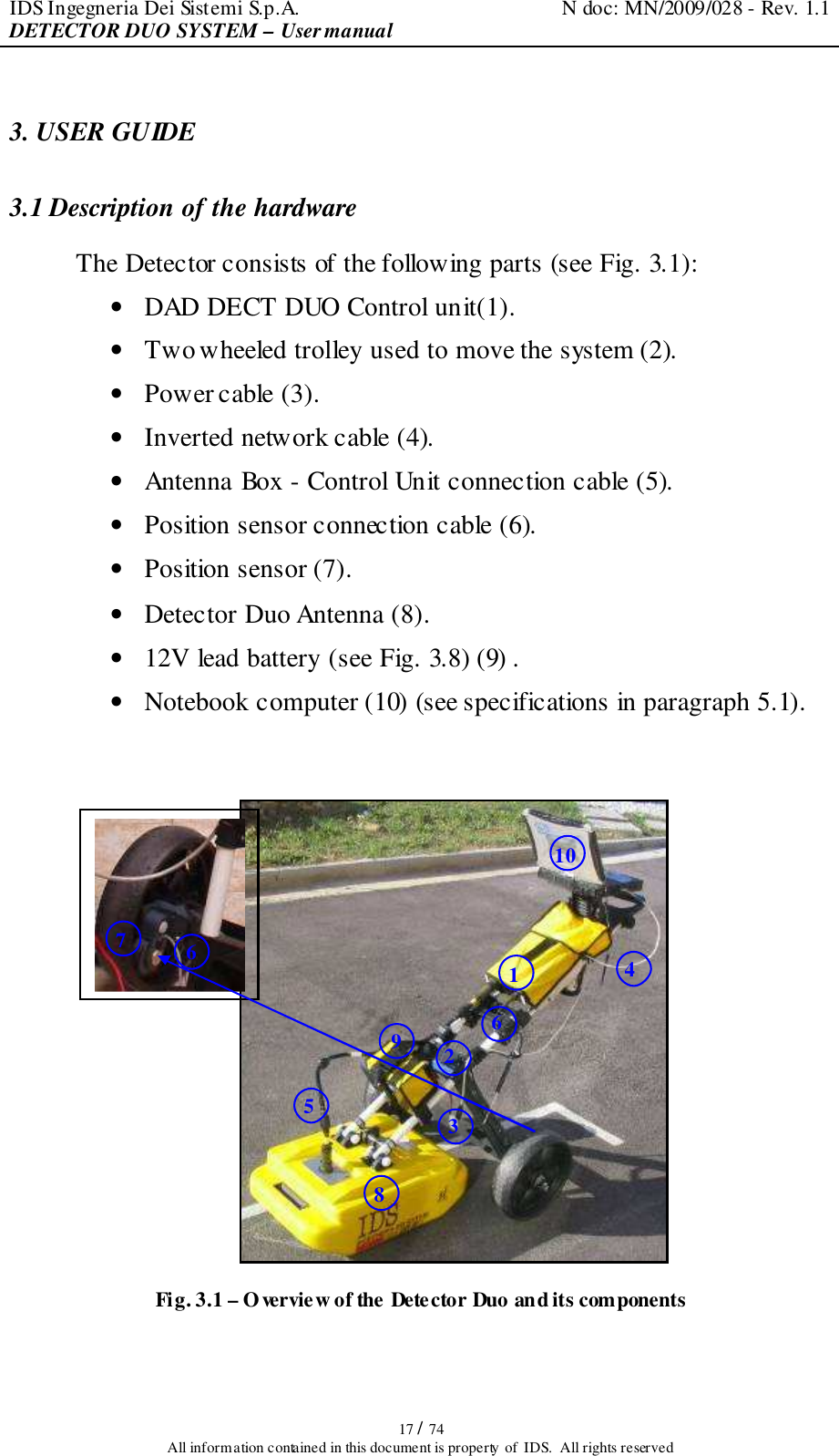
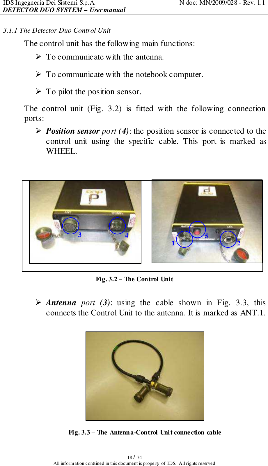
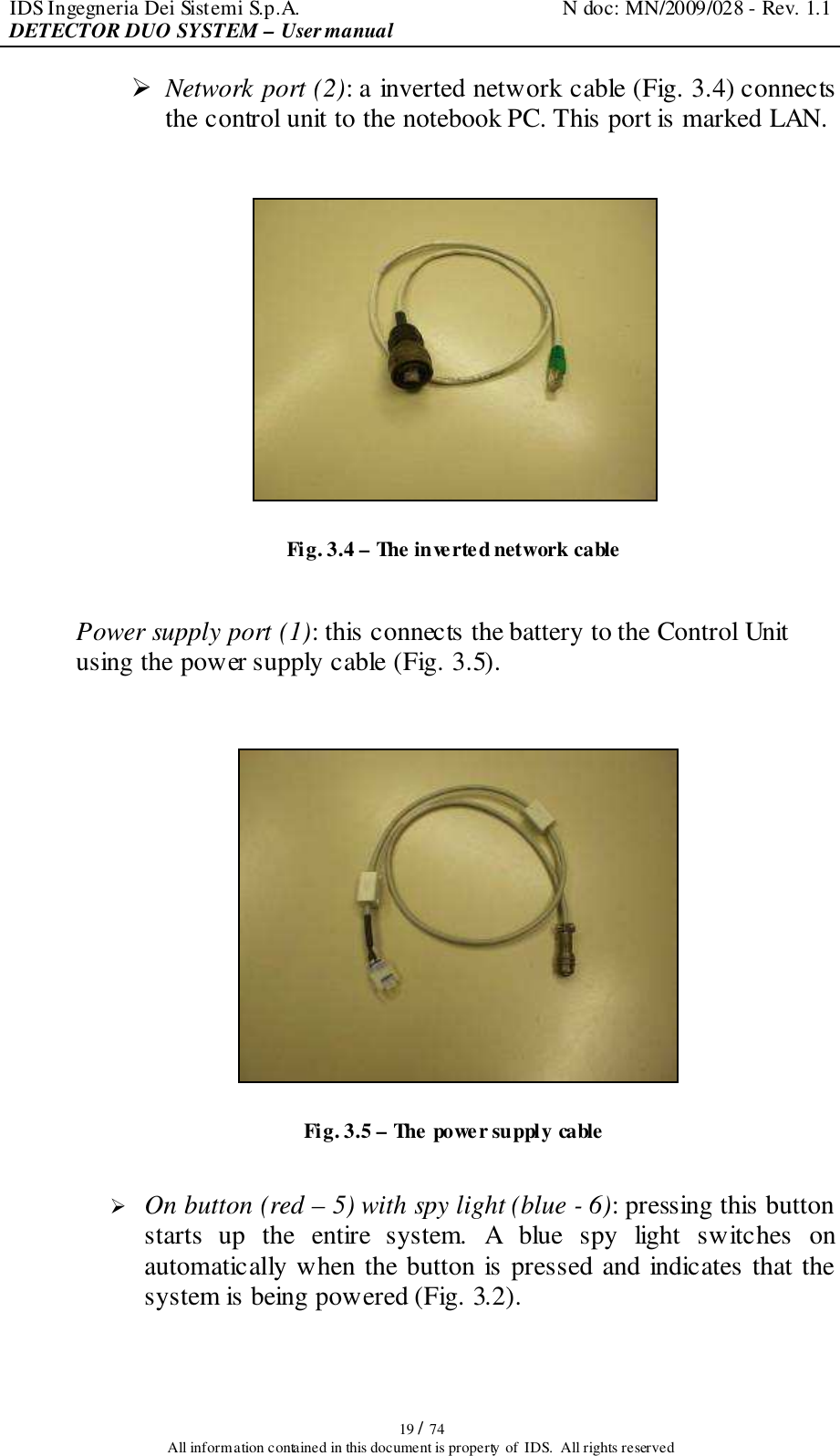
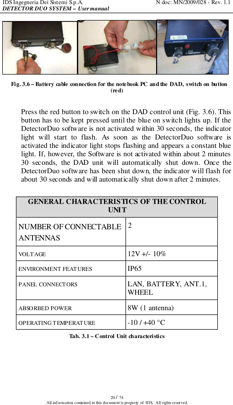
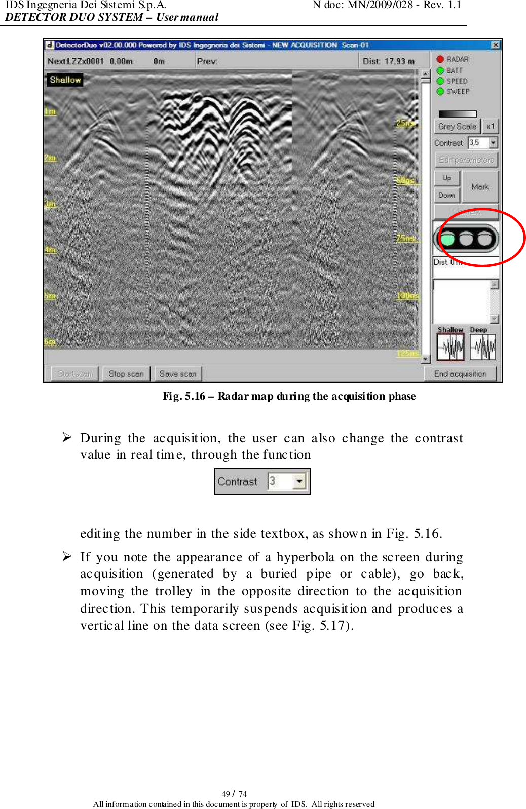
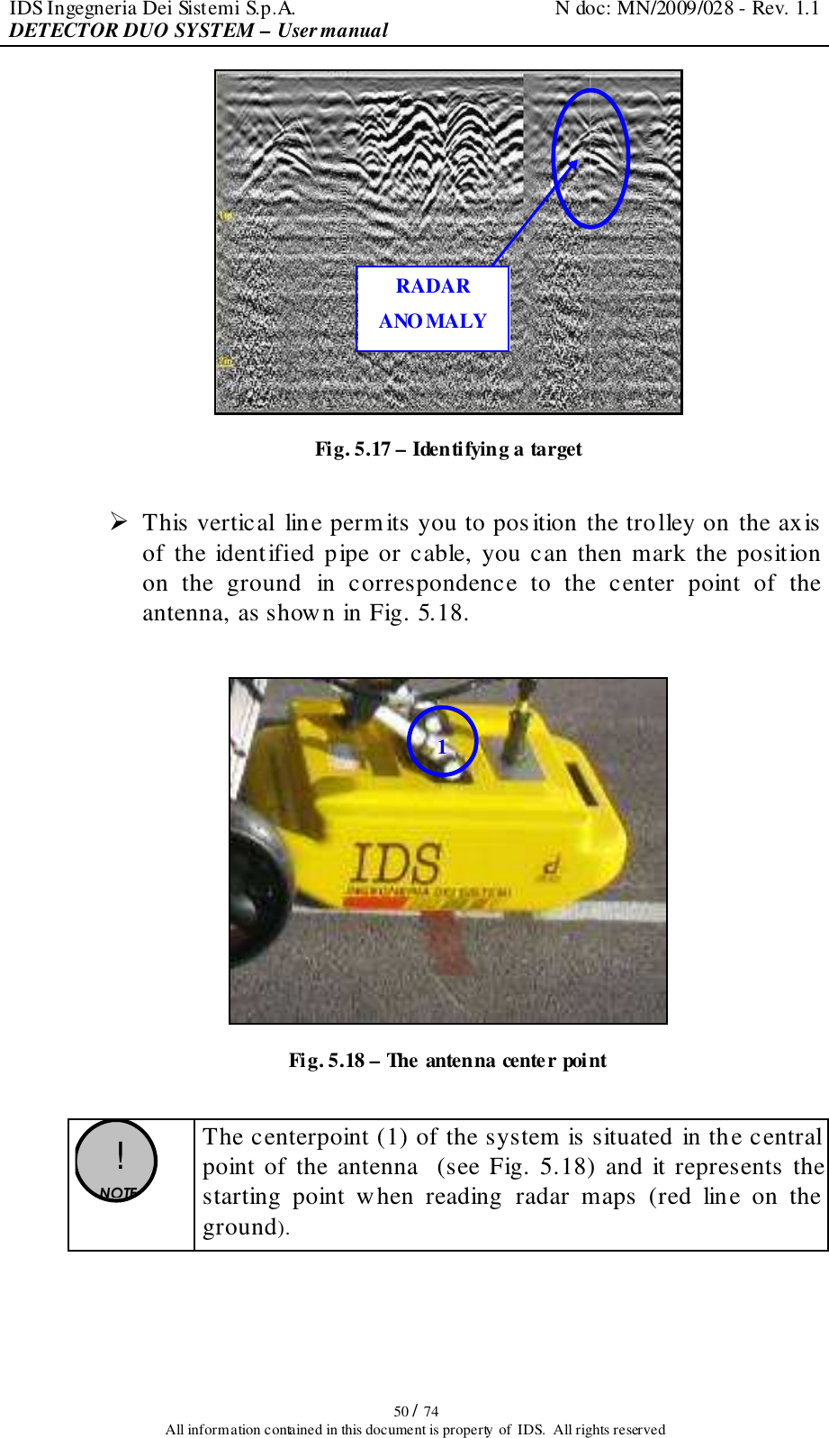
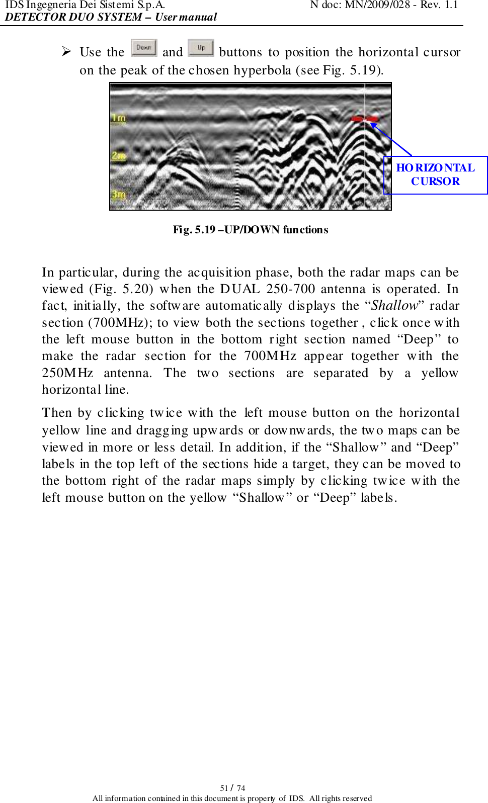
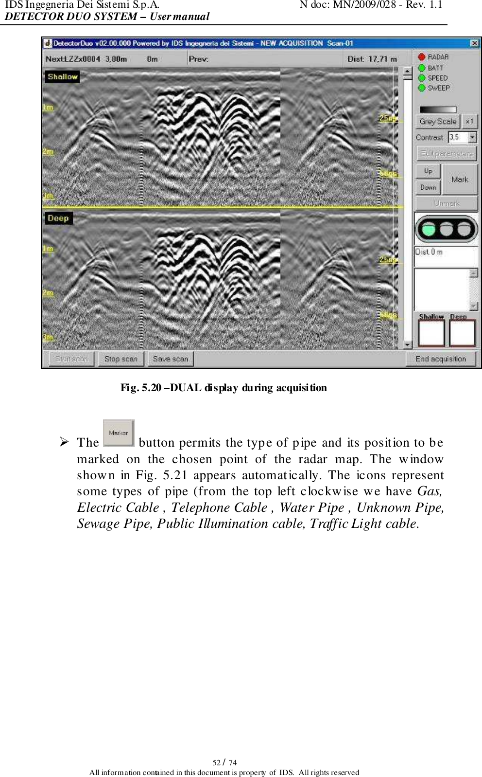
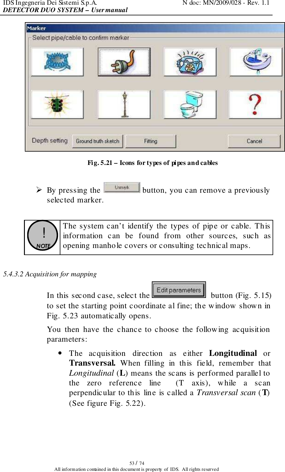
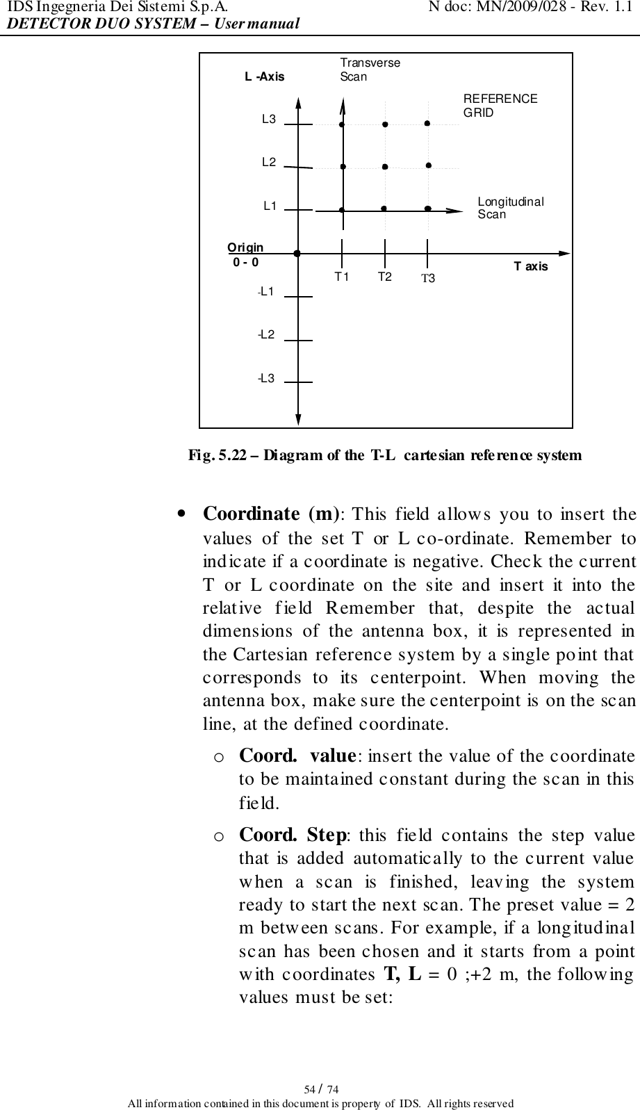
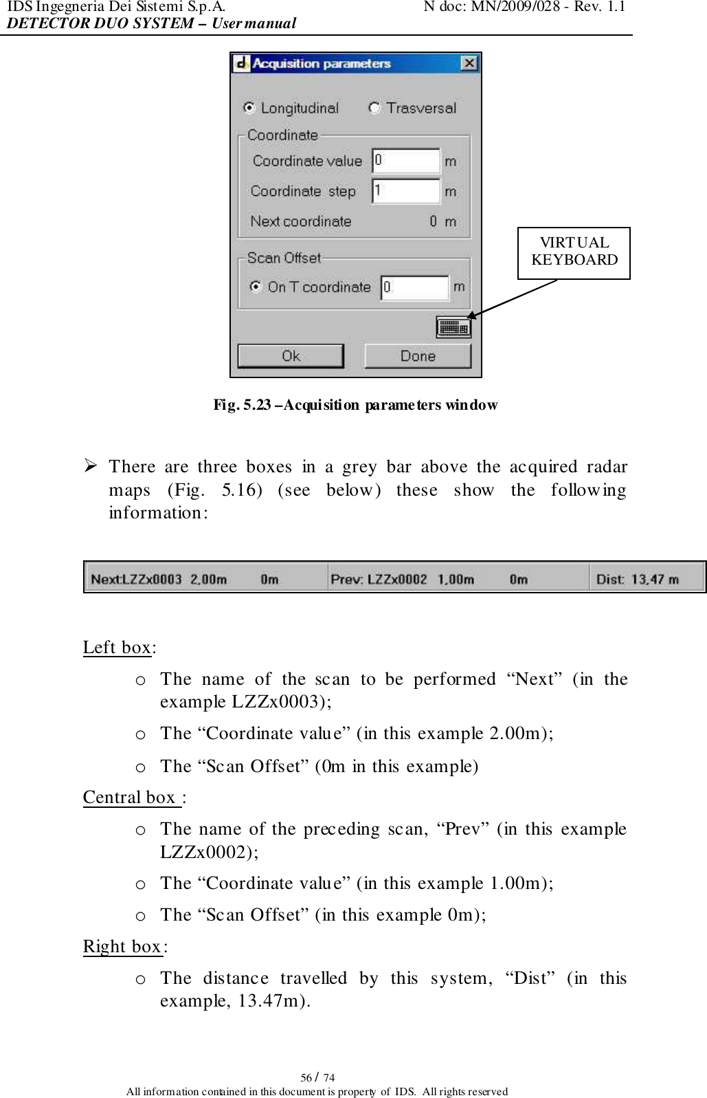
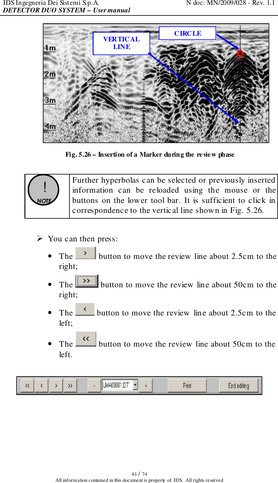
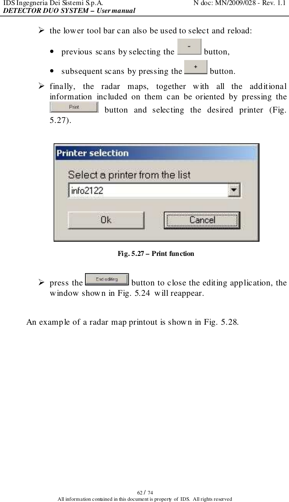
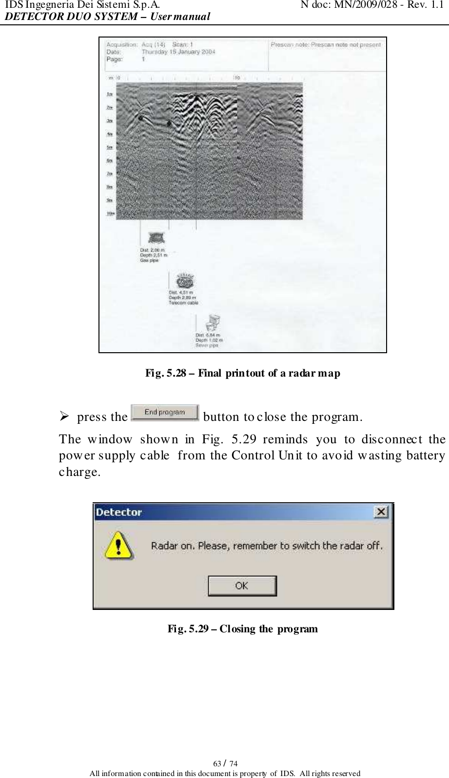
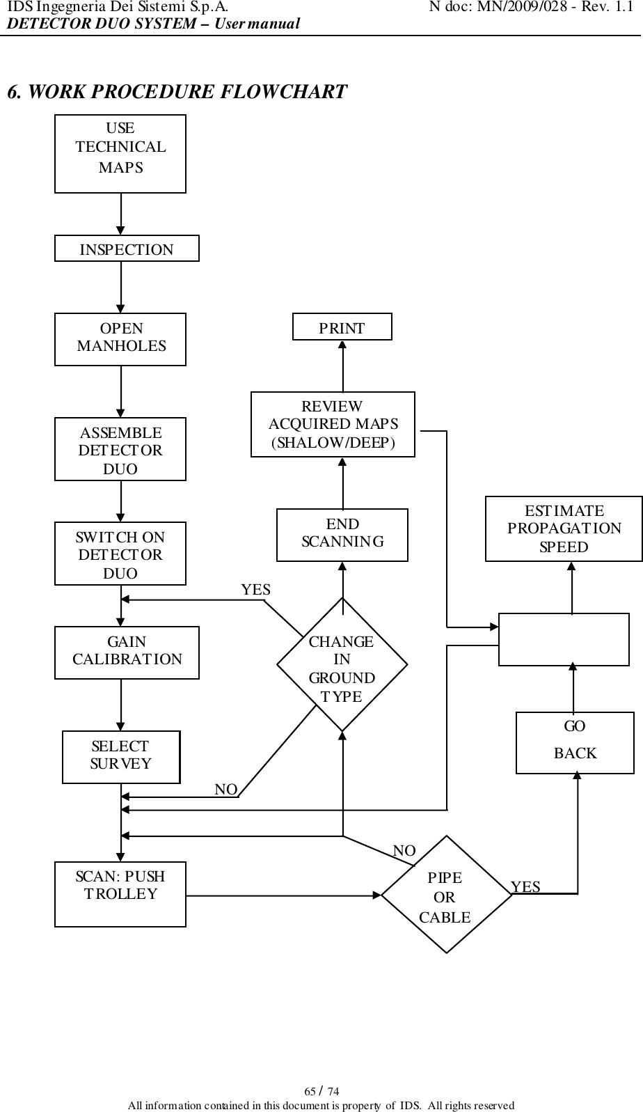
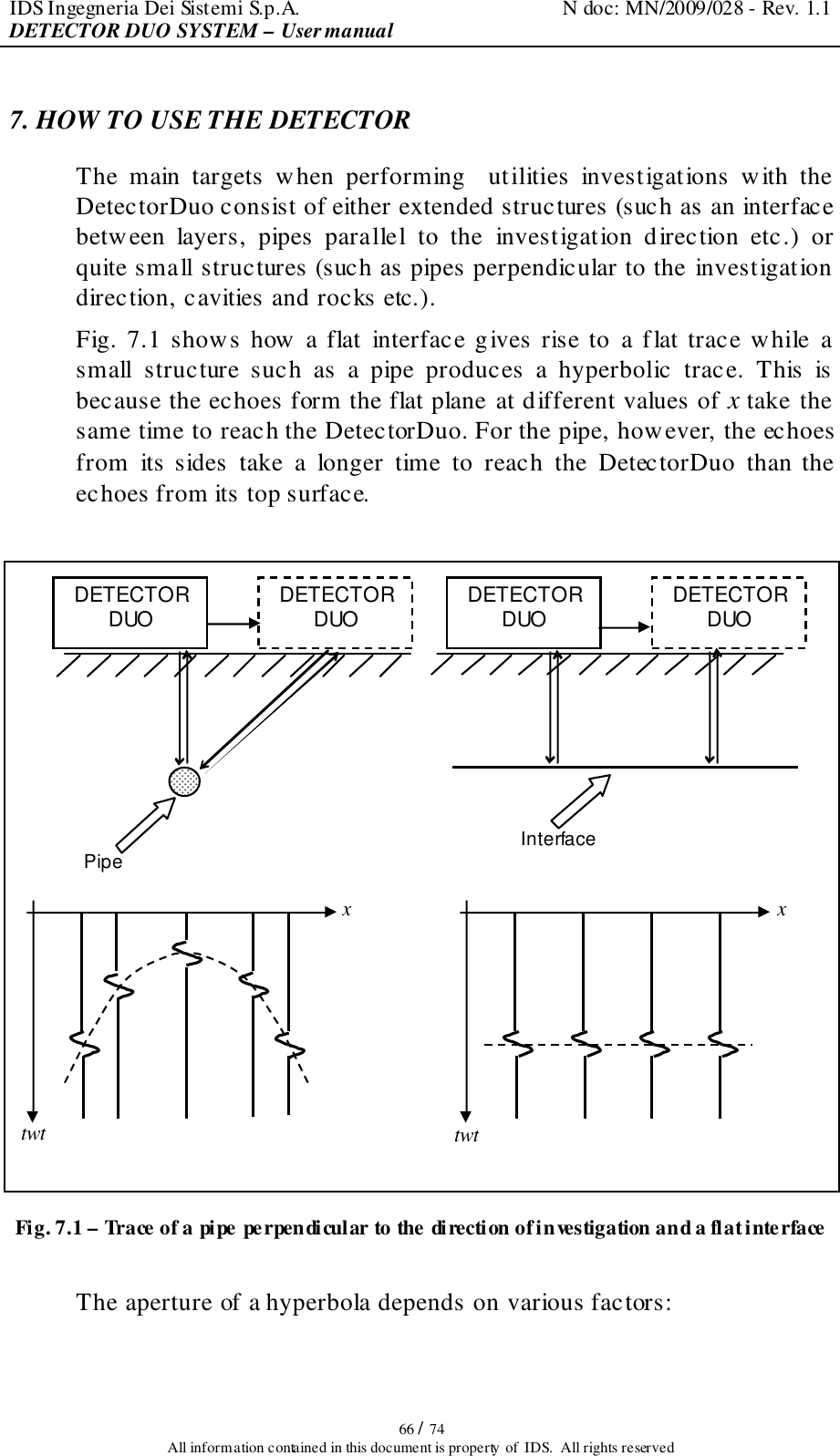
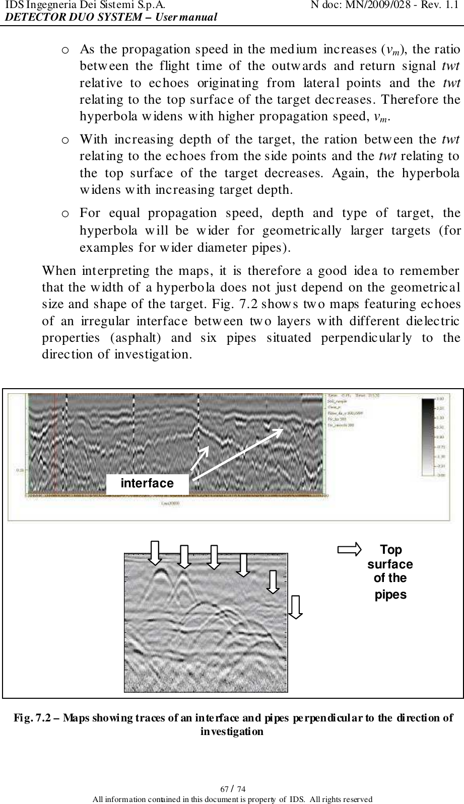
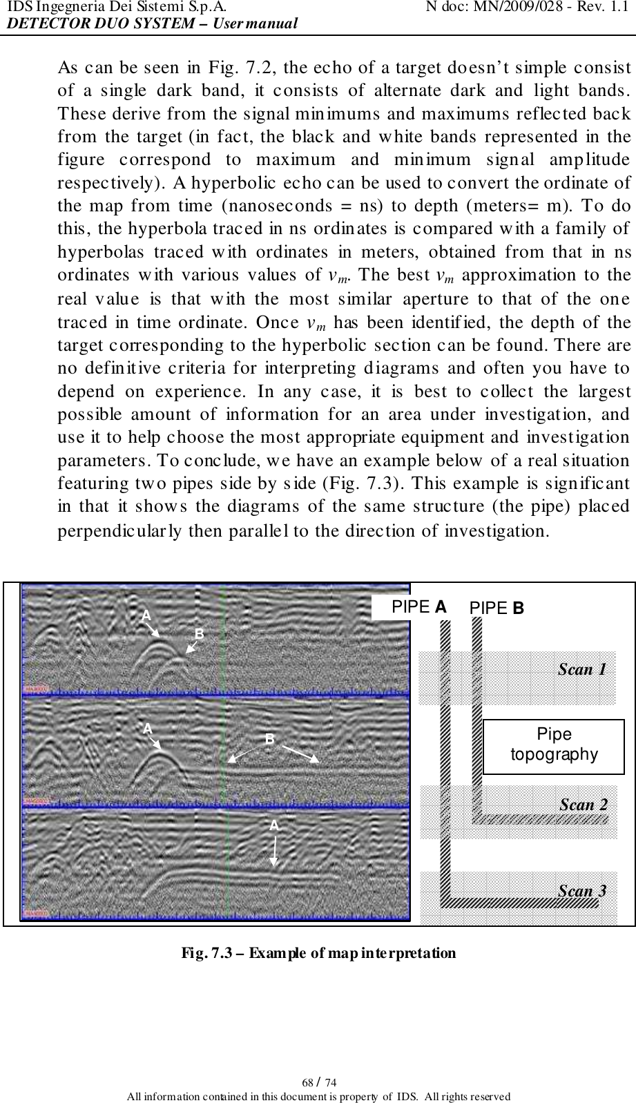
DETECTOR_DUO user manual

Tot pag. N°. = 74    - PRO/010/M1 Rev 4 -  INGEGNERIA DEI SISTEMI S.p.A.   Rev. 1.1 N°doc: MN/2009/028 Config.: DETECTOR DUO-PRCS-OUT-MN   DETECTOR DUO  USER MANUAL         DETECTOR DUO SYSTEM – User manual                                            Pisa, 12/02/2010
IDS Ingegneria Dei Sistemi S.p.A.  N doc: MN/2009/028 - Rev. 1.1 DETECTOR DUO SYSTEM – User manual   2 / 74 All information contained in this document is property of  IDS.  All rights reserved KEY WORDS  GEORADAR, DETECTOR DUO, ANTENNA  SUMMARY  This manual contains a complete description of the Detector Duo radar system, detailing the assembly procedure, the correct use of the data acquisition software, the work procedure and the general operating procedures of the system.  Document Evolution Revision  Data  Reason of modification Rev. 1.0  09/07/2009  First edition. It has been added a warning disclaimer and a new installation kit. Rev. 1.1  12/02/2010  FCC Information updated   SW Versions covered by this manual DETECTOR DUO V.02.00.000, 02.00.001, 02.00.006    OUR CONTACTS  IDS Ingegneria dei Sistemi S.p.A. – GeoRadar Division Via Sterpulino, 20 56121 Ospedaletto (PISA) - ITALIA Tel: +39.050.967111 Fax: +39.050.967121 inforis@ids-spa.it  Customer Care department: customercare.gpr@ids-spa.it Tel.: +39.050.967122  Sales & Marketing department: sales.gpr@ids-spa.it Tel.: +39.050.967123/24/43
IDS Ingegneria Dei Sistemi S.p.A.  N doc: MN/2009/028 - Rev. 1.1 DETECTOR DUO SYSTEM – User manual   3 / 74 All information contained in this document is property of  IDS.  All rights reserved DISCLAIMER  IDS  WILL  NOT  BE  HELD  RESPONSIBLE  FOR  THE  CONSEQUENCES  OF  AN IMPROPER USE OF THE EQUIPMENT AND/OR THE SOFTWARE.  THIS  SOFTWARE  MAY  INCLUDE  AUTOMATED  DATA  PROCESSING  AND ANALYSIS TOOLS.  WHILE  EVERY  EFFORT  IS  MADE  TO  ENSURE  THE  ACCURACY  OF  THE INFORMATION  PROVIDED  BY  THOSE  TOOLS,  THEY  MUST  NOT  BE INTENDED AS A SUBSTITUTE FOR INTELLIGENT ANALYSIS; RATHER, THEY HAVE  TO  BE  INTENDED  AS  AN  ADVISOR  AND  THE  USER  MUST  NOT COMPLETELY  RELY  ON  THE  RESULTS  PROVIDED  BY  THEM  TO GIVE  THE COMPLETE ANSWER. IDS  INGEGNERIA  DEI  SISTEMI  SPA  ASSUMES  NO  LIABILITY  FOR  ANY DIRECT,  INDIRECT,  SPECIAL, INCIDENTAL  OR  CONSEQUENTIAL  DAMAGES OR  INJURIES  CAUSED  BY  SUCH  RELIANCE  ON  THE  ACCURACY, RELIABILITY,  OR  TIMELESS  OF  THE  INFORMATION  PROVIDED  BY  THOSE TOOLS. ANY PERSON OR ENTITY WHO RELIES ON INFORMATION OBTAINED FROM THE AUTOMATED DATA PROCESSING/ANALYSIS TOOLS ONLY, DOES SO AT HIS OR HER OWN RISK
IDS Ingegneria Dei Sistemi S.p.A.  N doc: MN/2009/028 - Rev. 1.1 DETECTOR DUO SYSTEM – User manual   4 / 74 All information contained in this document is property of  IDS.  All rights reserved CONFORMITY TO EUROPEAN REGULATIONS  The  equipment  conforms  to  the  following  requirements  set  by  EC regulations,  including  subsequent  modifications,  and  to  the  legislation  set by the member states that implement these regulations:  1999/05/EEC Radio Directive Warning:  this  equipment  is  destined  for  use  in  industrial  environments (Class  A  apparatus).  In  residential,  commercial  and  light  industry environments, this apparatus may generate radio interference: in this case, the  user  may  be  required  to  operate  while  taking  appropriate countermeasures. The apparatus is sensitive to the presence of external electromagnetic fields, which may reduce its performance.        RADIO-FREQUENCY EXPOSURE COMPLIANCE   This product  operated is usually operated at least 1 m from the operator.  Typical  power  density  levels  at  a  distance  of  1  m  or  greater  is  below  1 µW/cm2    (0.01  W/m2)  which  are  far  below  the  levels  specified  by  the current regulations.  Thus,  this  product  pose  no  health  and  safety  risk  when operated  in  the normal manner of intended use.
IDS Ingegneria Dei Sistemi S.p.A.  N doc: MN/2009/028 - Rev. 1.1 DETECTOR DUO SYSTEM – User manual   5 / 74 All information contained in this document is property of  IDS.  All rights reserved   ! WARNING   CLEANING INFORMATION  Before  cleaning  any  external  parts  of  the  apparatus,  make  sure that  all  cables  have  been  disconnected,  including  the  power supply cable. If a damp cloth is used, make sure it is not too wet, to  avoid  any  damage  to  the  electrical  components  of  the equipment.  Wait  until  the  equipment  is  totally  dry  before reconnecting the cables. The Detector Duo should be cleaned periodically using a damp cloth. Do not use solvents or abrasive detergents. Do  not  apply  liquid  directly  to  the  electrical  contacts  of  the various  connectors.  If  a  specific  spray  is  used  to clean  the  PC TFT monitor, make sure it is not flammable; ion any case, do not spray it directly on the screen, instead, spray it onto the cleaning cloth.
IDS Ingegneria Dei Sistemi S.p.A.  N doc: MN/2009/028 - Rev. 1.1 DETECTOR DUO SYSTEM – User manual   6 / 74 All information contained in this document is property of  IDS.  All rights reserved     BATTERIES REMOVAL INFORMATION  Laptop Batteries: Manufacturer: PANASONIC Type: Li-ion Ni Characteristics: 10.65V 5.7Ah Removal instructions: 1. turn off the laptop; 2. open the drawer with the symbol of the batteries; 3. extract the battery pack pulling the tab.   Radar batteries: Manufacturer: FIAMM FG21202 / SAFT MP176065 Type: rechargeable lead acid / rechargeable lithium-ion Characteristics: 12V & 12Ah / 15V & 6.8Ah Removal instructions: 1. disconnect the battery from the instrument: a. pull the connector wings; b. separate the connectors; 2. remove the battery from the cover (optional) opening the strap.
IDS Ingegneria Dei Sistemi S.p.A.  N doc: MN/2009/028 - Rev. 1.1 DETECTOR DUO SYSTEM – User manual   7 / 74 All information contained in this document is property of  IDS.  All rights reserved     RECICLYING   The crossed out wheeled bin symbol shown on the equipment indicates that the product must be recycled separately from other waste at the end of  its useful life.  Separate waste disposal of this product at the end of  its useful  life will be organised  and  managed  by  IDS.  When  you  decide  to  dispose  of  the equipment, contact IDS and follow the system that IDS has set up to permit the separate collection of the apparatus at its life end.  Adequate  separate  collection  for  its  subsequent  recycling,  treatment  and environmental  friendly  disposal  contribute  towards  avoiding  any unnecessary effects on the environment and to health and favour the reuse or recycling of the materials that make up the equipment. Unauthorised disposal of  this  product  as  unsorted  waste  by  its  possessor  will  lead  to  an administrative penalty foreseen by national regulations.
IDS Ingegneria Dei Sistemi S.p.A.  N doc: MN/2009/028 - Rev. 1.1 DETECTOR DUO SYSTEM – User manual   8 / 74 All information contained in this document is property of  IDS.  All rights reserved  WARRANTY CERTIFICATE CONDITIONS  1) IDS  Ingegneria  dei  Sistemi  S.p.A,  hereinafter  referred  to  as  IDS,  warrants  hardware/software products for a period of 12 months from the delivery date to the original customer; 2) The delivery date is certified by the “ Warranty Registration Form”; 3) IDS’s hardware products will be free  from defects in materials workmanship under normal use and service; 4) IDS’s obligation is limited to repairing or replacing parts or equipment which are returned to IDS, without  alteration  or  further  damage,  and  which  in  IDS  s  judgment,  were  defective  or  became defective during normal use; 5) IDS’ software will have to be installed on a PC according to the requirement of the IDS hardware ( see IDS User’s Guide the Software Data Acquisition); 6) IDS’ s software products designed by  IDS  for use  for IDS hardware products are warranted not to fail to execute their programming instructions due to defects during the warranty period, provided they are properly installed on IDS hardware products. IDS does not warrant if the IDS software will be used and operated in hardware and software combinations not selected by IDS; 7) IDS  does  not  assumes  any  liability  for  any  direct,  indirect,  special,  incidental  or  consequential damages or injuries  caused by proper or improper operation of its equipment  whether defective or not defective; 8) This software may include automated data processing and analysis tools. While every effort is made to ensure the accuracy of the information provided by those tools, they must not be intended as a substitute for intelligent analysis; rather, they have to be intended as an advisor and the user must not completely rely on the  results provided by them to give the  complete answer.  IDS assumes no liability  for  any  direct,  indirect  special,  incidental  or  consequential damages  or  injuries  caused by such reliance on the accuracy, reliability, or timeliness of the information provided by those tools. Any  person  or  entity  who  relies  on  information  obtained  from  the  automated  data processing/analysis tools only, does so at his or her own risk; 9) IDS’s warranty does not extend and shall not apply to: a) Products which have been repaired or altered by other than IDS personnel; b) Products which have been subjected to misuse, neglect, accident or improper installation; c) Products  in  which  have  been  installed  Hardware/Software  accessories  not  supplied  by  IDS and/or without any approval by IDS; d) Products  which have  been  connected  to  equipment  different  from  the  ones  supplied  by  IDS (except the PC data Logger which must conform to IDS specifications; e) Products which have been damaged by natural disaster or calamities. 10) Before returning any equipment to IDS , you have to contact the IDS Customer Care Office that will authorize you to return the material to be repaired; 11)  Once the parts/equipment to be repaired  arrive to  IDS, IDS may inspect the defective products to verify they are  eligible  for repair or replacement. All packing must be saved  for inspection purpose in order to assist IDS to understand the cause of the defects. IDS, will not be obliged to repair, or replace  for  products  returned  as  defective but  damaged  from  abuse,  misuse,  neglicence  ,  accident loss or damage in transit; 12) The  final  clients,  is  responsible  for  ensuring  the  defective  products  returned  to  be  properly packaged; 13) The  above  warranty  are  sole  and  exclusive,  and  no  other  warranty,  whether  written  or  oral,  is expressed or implied.
IDS Ingegneria Dei Sistemi S.p.A.  N doc: MN/2009/028 - Rev. 1.1 DETECTOR DUO SYSTEM – User manual   9 / 74 All information contained in this document is property of  IDS.  All rights reserved  IMPORTANT NOTE FOR THE US CUSTOMERS FCC ID: UFW-DETDUO-FW This device complies with part 15 of the FCC Rules: Operation is subject to the following conditions: 1. This device may not cause harmful interference, and 2. This device must accept any interference received, Including interference that may cause undesired operation Warning:  Changes  or  modifications to  this unit not  expressly  approved by  the party  responsible  for  compliance could void the user’s authority to operate the equipment. Operation of  this device  is  restricted  to law  enforcement,  fire  and  rescue  officials, scientific  research  institutes, commercial mining companies, and construction companies. Operation by any other party is a violation of 47 U.S.C. § 301 and could subject the operator to serious legal penalties. Coordination Requirements. (a) UWB imaging systems require coordination through the FCC before the equipment may be used. The operator shall comply with any constraints on equipment usage resulting from this coordination. (b) The users of UWB imaging devices shall supply detailed operational areas to the FCC Office o f Engineering and Technology  who  shall  coordinate  this  information  with  the  Federal  Government  through  the  National Telecommunications and Information Administration. The information provided by the UWB operator shall include the name, address and other pertinent contact information of the user, the desired geographical area of operation, and the FCC ID number and other nomenclature of the UWB device. This material shall be submitted to the following address: Frequency Coordination Branch., OET Federal Communications Commission 445 12th Street, SW Washington, D.C. 20554 ATTN: UWB Coordination (d)  Users of  authorized,  coordinated UWB systems  may  transfer  them  to other  qualified  users  and  to  different locations  upon  coordination  of  change  of  ownership  or  location  to  the  FCC  and  coordination  with  existing authorized operations. (e)  The NTIA/FCC  coordination  report shall  include  any needed constraints  that  apply to  day-to-day operations. Such  constraints  could  specify prohibited  areas of  operations  or  areas located  near  authorized  radio stations  for which additional coordination is required before operation of the UWB equipment. If additional local coordination is required, a local coordination contact will be provided. (f) The coordination of routine UWB operations shall not take longer than 15 business days from the receipt of the coordination request by NTIA. Special temporary operations may be handled with an expedited turn-around time when circumstances warrant. The operation of UWB systems in emergency situations involving the safety of life or property  may  occur  without  coordination provided  a  notification procedure, similar to  that  contained  in  CFR47 Section 2.405(a)-(e), is followed by the UWB equipment user.  Notice: Use of this device as a wall imaging system is prohibited by FCC regulations.  IMPORTANT NOTE FOR THE CANADIAN CUSTOMERS IC Certification Number: IC:8991A –DETDUOFW This device complies with the requirements of IC Standard RSS-220 This Ground Penetrating Radar Device shall be operated only when in contact with or within 1 m of the ground. This Ground Penetrating  Radar  Device shall be  operated only by law  enforcement  agencies,  scientific  research institutes,  commercial  mining  companies,  construction  companies,  and  emergency  rescue  or  firefighting organizations.
IDS Ingegneria Dei Sistemi S.p.A.  N doc: MN/2009/028 - Rev. 1.1 DETECTOR DUO SYSTEM – User manual   10 / 74 All information contained in this document is property of  IDS.  All rights reserved INDEX 1. Introduction..................................................................................................................13 1.1 Scope....................................................................................................................14 1.2 Trademarks...........................................................................................................14 1.3 Acronyms and Definitions.......................................................................................14 1.3.1 Acronyms................................................................................................... 14 1.3.2 Definitions.................................................................................................. 14 2. Overview.......................................................................................................................16 2.1 How to use this manual..........................................................................................16 2.2 Background knowledge required.............................................................................16 3. User guide.....................................................................................................................17 3.1 Description of the hardware...................................................................................17 3.1.1 The Detector Duo Control Unit....................................................................... 18 3.1.2 The antenna box........................................................................................... 21 3.1.3 Power supply............................................................................................... 21 3.1.3.1 Charge level and battery replacement...................................................... 22 4. Assembly procedure......................................................................................................23 4.1 How to assemble the trolley....................................................................................23 4.2 Connecting the cables............................................................................................25 4.2.1 Connecting the battery................................................................................... 25 4.2.2 Mounting the antenna and connecting its cables.................................................. 25 4.2.3 Mounting the PC notebook and the sunshade..................................................... 27 4.2.4 Connecting the position sensor........................................................................ 29 4.2.5 Removing the trolley wheels........................................................................... 29 5. The acquisition software...............................................................................................31 5.1 The Notebook Computer.........................................................................................31 5.1.1 Hammerhead rugged tablet PC........................................................................ 31 5.1.2 Panasonic Toughbook rugged tablet PC............................................................ 34 5.2 Basic characteristics of the notebook PC.................................................................35 5.3 Software installation and configuration...................................................................36 5.4 The operational phases..........................................................................................41 5.4.1 Running the software .................................................................................... 41 5.4.2 Pre-acquisition commands.............................................................................. 42 5.4.3 Commands used during acquisition.................................................................. 46 5.4.3.1 Acquisition for on-site detection ............................................................ 48 5.4.3.2 Acquisition for mapping....................................................................... 53 5.4.4 Depth calibration.......................................................................................... 57 5.4.5 Post-acquisition commands ............................................................................ 58 5.5 Error messages......................................................................................................64 6. Work procedure flowchart............................................................................................65
IDS Ingegneria Dei Sistemi S.p.A.  N doc: MN/2009/028 - Rev. 1.1 DETECTOR DUO SYSTEM – User manual   11 / 74 All information contained in this document is property of  IDS.  All rights reserved 7. How to use the detector.................................................................................................66 8. On line assistance..........................................................................................................69 8.1 Remote assistance using Webex Support Center.......................................................69 8.1.1 How to use the Webex service......................................................................... 69 Appendix A - The preliminary investigation.....................................................................73 Appendix B - The technical maps.....................................................................................73 Appendix C - Opening manholes......................................................................................74  FIGURES INDEX  FIG. 3.1 – OVERVIEW OF THE DETECTOR DUO AND ITS COMPONENTS............................... 17 FIG. 3.2 – THE CONTROL UNIT............................................................................................. 18 FIG. 3.3 – THE ANTENNA-CONTROL UNIT CONNECTION CABLE ......................................... 18 FIG. 3.4 – THE INVERTED NETWORK CABLE........................................................................ 19 FIG. 3.5 – THE POWER SUPPLY CABLE................................................................................. 19 FIG. 3.6 – BATTERY CABLE CONNECTION FOR THE NOTEBOOK PC AND THE DAD,  SWITCH ON BUTTON (RED)...................................................................................................... 20 FIG. 3.7 –IDS ATS DUAL 250-700 ANTENNA BOX.................................................................. 21 FIG. 3.8 – LEAD BATTERY.................................................................................................... 21 FIG. 3.9 – BATTERY STATUS SIGNAL (LEFT) AND THE BATTERY CHARGER (RIGHT).......... 22 FIG. 4.1 – TROLLEY FOLDED IN ITS CARRIER BAG.............................................................. 23 FIG. 4.2 – OPENING THE TROLLEY....................................................................................... 24 FIG. 4.3 – UPPER BLOCKING MECHANISM........................................................................... 24 FIG. 4.4 – BATTERY AND CABLING SUPPORT ...................................................................... 25 FIG. 4.5 – FIXING THE ANTENNA BOX................................................................................. 26 FIG. 4.6 –ANTENNA-RADAR CONNECTION.......................................................................... 26 FIG. 4.7 – TROLLEY-ANTENNA LOCKING SYSTEM............................................................... 27 FIG. 4.8 – FIXING THE NOTEBOOK PC.................................................................................. 27 FIG. 4.9 – ASSEMBLING THE SUNSHADE.............................................................................. 28 FIG. 4.10 – SUNSHADE ON HORIZONTAL SCREEN................................................................ 28 FIG. 4.11 – CONNECTING THE POSITION SENSOR................................................................. 29 FIG. 4.12 – REMOVING THE TROLLEY WHEELS ................................................................... 30 FIG. 5.1 – HAMMERHEAD RUGGED TABLET PC................................................................... 32 FIG. 5.2 – PANASONIC TOUGHBOOK CF-19 .......................................................................... 35 FIG. 5.3 – DETECTOR DUO SETUP ICON............................................................................... 36 FIG. 5.4 – DETECTOR DUO WELCOME WINDOW.................................................................. 36 FIG. 5.5 – SETUP TYPE WINDOW.......................................................................................... 37 FIG. 5.6 – PRE-INSTALLATION WINDOW.............................................................................. 37 FIG. 5.7 – INSTALLATION COMPLETED WINDOW................................................................ 38 FIG. 5.8 – SELECTING THE ETHERNET CARD (TCP/IP).......................................................... 39 FIG. 5.9 – CHANGING THE IP ADDRESS................................................................................ 40 FIG. 5.10 – ACQUISITION SOFTWARE ICON.......................................................................... 41
IDS Ingegneria Dei Sistemi S.p.A.  N doc: MN/2009/028 - Rev. 1.1 DETECTOR DUO SYSTEM – User manual   12 / 74 All information contained in this document is property of  IDS.  All rights reserved FIG. 5.11 – INITIALIZING WINDOW ...................................................................................... 42 FIG. 5.12 – GAIN CALIBRATION UNDERWAY....................................................................... 43 FIG. 5.13 –ADVANCED SETTINGS WINDOW......................................................................... 44 FIG. 5.14 –ACQUISITION SELECTION WINDOW.................................................................... 46 FIG. 5.15 –NEW ACQUISITION WINDOW............................................................................... 47 FIG. 5.16 – RADAR MAP DURING THE ACQUISITION PHASE................................................. 49 FIG. 5.17 – IDENTIFYING A TARGET..................................................................................... 50 FIG. 5.18 – THE ANTENNA CENTER POINT........................................................................... 50 FIG. 5.19 –UP/DOWN FUNCTIONS......................................................................................... 51 FIG. 5.20 –DUAL DISPLAY DURING ACQUISITION................................................................ 52 FIG. 5.21 – ICONS FOR TYPES OF PIPES AND CABLES.......................................................... 53 FIG. 5.22 – DIAGRAM OF THE T-L  CARTESIAN REFERENCE SYSTEM................................... 54 FIG. 5.23 –ACQUISITION PARAMETERS WINDOW................................................................ 56 FIG. 5.24 – DELETING A SURVEY......................................................................................... 59 FIG. 5.25 – HOW TO RENAME A SURVEY.............................................................................. 60 FIG. 5.26 – INSERTION OF A MARKER DURING THE REVIEW PHASE.................................... 61 FIG. 5.27 – PRINT FUNCTION................................................................................................ 62 FIG. 5.28 – FINAL PRINTOUT OF A RADAR MAP................................................................... 63 FIG. 5.29 – CLOSING THE PROGRAM.................................................................................... 63 FIG. 7.1 – TRACE OF A PIPE PERPENDICULAR TO THE DIRECTION OF INVESTIGATION AND A FLAT INTERFACE........................................................................................................ 66 FIG. 7.2 – MAPS SHOWING TRACES OF AN INTERFACE AND PIPES PERPENDICULAR TO THE DIRECTION OF INVESTIGATION.................................................................................. 67 FIG. 7.3 – EXAMPLE OF MAP INTERPRETATION................................................................... 68 FIG. 8.1 – MAIL SENT BY IDS TO THE CLIENT ...................................................................... 69 FIG. 8.2 – CLIENT DATA INSERTION FORM.......................................................................... 70 FIG. 8.3 – WEBEX SET UP WINDOW...................................................................................... 70 FIG. 8.4 – WELCOME TO WEBEX SUPPORT CENTER WINDOW ............................................. 71 FIG. 8.5 – COMMAND ACCEPTANCE WINDOW..................................................................... 72  TABLES INDEX TAB. 1.1 – CONTACT ADDRESSES FOR TECHNICAL AND SALES ASSISTANCE..................... 13 TAB. 3.1 – CONTROL UNIT CHARACTERISTICS.................................................................... 20
IDS Ingegneria Dei Sistemi S.p.A.  N doc: MN/2009/028 - Rev. 1.1 DETECTOR DUO SYSTEM – User manual   13 / 74 All information contained in this document is property of  IDS.  All rights reserved 1. INTRODUCTION The Detector Duo is an innovative system capable of detecting tubes and both metallic and non metallic cables buried underground.  Following  standard  radar  principles,  the  Detector  Duo  uses  a  high performance  electromagnetic  sensor  equipped  with  e.m.  transmitters and receivers. The fundamental characteristic of this system is the simultaneous use of two frequencies, permitting the identification of both shallow and deep utilities at the same time. The groundbreaking control unit is extremely compact and lightweight at just 1Kg , and is compatible with 2 ATS antennas with frequencies of 700MHz and 250MHz located in a single container. The simplicity of  this  instrument  means  that  a  brief  training  course  is sufficient  to permit it to be used correctly.   I.D.S. Ingegneria dei Sistemi S.p.A. – Georadar Division Via Sterpulino, 20 56121 Ospedaletto (PI) Sales & Marketing Department: Paolo Papeschi:  (p.papeschi@ids-spa.it) Tel.: +39.050.967123 Customer Care Department: Davide Morandi: (d.morandi@ids-spa.it); Valter Baroncini: (v.baroncini@ids-spa.it); Tel.: +39.050.967122 Fax: +39.050.967121 E-mail: inforis@ids-spa.it Web site: http://www.idsgeoradar.com/ Tab. 1.1 – Contact addresses for technical and sales assistance
IDS Ingegneria Dei Sistemi S.p.A.  N doc: MN/2009/028 - Rev. 1.1 DETECTOR DUO SYSTEM – User manual   14 / 74 All information contained in this document is property of  IDS.  All rights reserved The simple acquisition software and automatic data saving procedures operate  well  on  both  Windows  2000  Professional  and  Windows  XP Professional.  For  details  on  the  required  characteristics  of  the notebook PC, see Paragraph 5.1. From an operative point of view, the Detector Duo can perfectly adapt to all applications for pipe and cable detection in a typical roadworks environment, both over smooth and rough ground.  Contact  IDS  Georadar  Division  directly  for  all  technical  and commercial assistance.  1.1 Scope This  document  describes  how  to  use  the  Georadar  Detector  Duo, including both its hardware and software components. 1.2 Trademarks   WINDOWS 2000 PROFESSIONAL /WINDOWS XP PROFESSIONAL Microsoft Corporation  DETECTOR DUO IDS  Ingegneria  dei  Sistemi S.p.A.  1.3 Acronyms and Definitions 1.3.1 Acronyms DETECTOR DUO: double antenna digital pipe detection system. 1.3.2 Definitions Antenna  trolley:  a  unit  that  holds  all  the  equipment  necessary  for acquisition in the field.  Centerpoint : the ideal point of the trolley, situated in the center of the box  containing  the  antennas;  it  represents  the  starting  point  for  all scans.
IDS Ingegneria Dei Sistemi S.p.A.  N doc: MN/2009/028 - Rev. 1.1 DETECTOR DUO SYSTEM – User manual   15 / 74 All information contained in this document is property of  IDS.  All rights reserved Data processing: this is applied to the raw data to permit the acquired sections to be viewed in a comprehensible way. Field survey: a group of field acquisitions relating to a single survey. Handle: a extractable handle  is gripped by the operator to move the antenna trolley. Maps:  graphics  showing  the  change  in  received  radar  signal  (signal intensity in gray scale) with respect to the scanning direction.  Position  sensor:  a  distance  measurement  device  fixed  inside  one  of the trolley wheels, which constantly signals the distance travelled from the start of the scan back to the Control Unit . Raw data: unprocessed data obtained during a field survey. Receiver : part of the antenna dedicated to detecting the signals. It is lodged in the same container as the transmitter. Scan: a single movement of the antenna trolley from the beginning to the end of a pre-established path  Setup: initialization of a piece of equipment or a software process. Survey: the name given to a collection of scans, which together cover all the areas of a large investigation: typically an entire town or a large urban area Transmitter:  part  of  the  antenna  dedicated  to  emitting  the  radar signals. It is lodged in the same container as the receiver. Utilities:  the  objects  the  Detector  Duo  searches  for,  i.e.  pipes supplying gas and water, electricity cables, etc.
IDS Ingegneria Dei Sistemi S.p.A.  N doc: MN/2009/028 - Rev. 1.1 DETECTOR DUO SYSTEM – User manual   16 / 74 All information contained in this document is property of  IDS.  All rights reserved 2. OVERVIEW 2.1 How to use this manual  This Detector Duo user manual is subdivided as follows: • Chap. 1: Introduction. • Chap. 2: Overview. • Chap. 3: User guide. • Chap. 4: Assembly procedure. • Chap. 5: The acquisition software. • Chap. 6: Work procedure flowchart. • Chap. 7: How to use Detector Duo. 2.2 Background knowledge required The  following  background  knowledge  is  required  to  be  able  to  use Detector Duo:  Windows  2000  Professional  or  Windows  XP  Professional operating system. For any difficulties with this aspect, the user should make reference to publications available on this topic or to the manual provided with the system.
IDS Ingegneria Dei Sistemi S.p.A.  N doc: MN/2009/028 - Rev. 1.1 DETECTOR DUO SYSTEM – User manual   17 / 74 All information contained in this document is property of  IDS.  All rights reserved 3. USER GUIDE 3.1 Description of the hardware The Detector consists of the following parts (see Fig. 3.1): • DAD DECT DUO Control unit(1). • Two wheeled trolley used to move the system (2). • Power cable (3). • Inverted network cable (4). • Antenna Box - Control Unit connection cable (5). • Position sensor connection cable (6). • Position sensor (7). • Detector Duo Antenna (8). • 12V lead battery (see Fig. 3.8) (9) . • Notebook computer (10) (see specifications in paragraph 5.1).    Fig. 3.1 – Overview of the Detector Duo and its components  1 6 5 4 3 2 8  7  6 10 9
IDS Ingegneria Dei Sistemi S.p.A.  N doc: MN/2009/028 - Rev. 1.1 DETECTOR DUO SYSTEM – User manual   18 / 74 All information contained in this document is property of  IDS.  All rights reserved 3.1.1 The Detector Duo Control Unit The control unit has the following main functions:  To communicate with the antenna.  To communicate with the notebook computer.  To pilot the position sensor. The  control  unit  (Fig.  3.2)  is  fitted  with  the  following  connection ports:  Position sensor port (4): the position sensor is connected to the control  unit  using  the  specific  cable.  This  port  is  marked  as WHEEL.   Fig. 3.2 – The Control Unit   Antenna  port  (3): using  the  cable  shown  in  Fig.  3.3,  this connects the Control Unit to the antenna. It is marked as ANT.1.   Fig. 3.3 – The Antenna-Control Unit connection cable  4 3  2 1  5
IDS Ingegneria Dei Sistemi S.p.A.  N doc: MN/2009/028 - Rev. 1.1 DETECTOR DUO SYSTEM – User manual   19 / 74 All information contained in this document is property of  IDS.  All rights reserved  Network port (2): a inverted network cable (Fig. 3.4) connects the control unit to the notebook PC. This port is marked LAN.   Fig. 3.4 – The inverted network cable   Power supply port (1): this connects the battery to the Control Unit using the power supply cable (Fig. 3.5).     Fig. 3.5 – The power supply cable   On button (red – 5) with spy light (blue - 6): pressing this button starts  up  the  entire  system.  A  blue  spy  light  switches  on automatically when the button is pressed and indicates that the system is being powered (Fig. 3.2).
IDS Ingegneria Dei Sistemi S.p.A.  N doc: MN/2009/028 - Rev. 1.1 DETECTOR DUO SYSTEM – User manual   20 / 74 All information contained in this document is property of  IDS.  All rights reserved  Fig. 3.6 – Battery cable connection for the notebook PC and the DAD,  switch on button (red)  Press the red button to switch on the DAD control unit (Fig. 3.6). This button has to be kept pressed until the blue on switch lights up. If the DetectorDuo software is not activated within 30 seconds, the indicator light  will  start  to  flash.  As  soon  as  the  DetectorDuo  software  is activated the indicator light stops flashing and appears a constant blue light. If, however, the Software is not activated within about 2 minutes 30  seconds,  the  DAD  unit  will  automatically  shut  down.  Once  the DetectorDuo software has been shut down, the indicator will flash for about 30 seconds and will automatically shut down after 2 minutes.  GENERAL CHARACTERISTICS OF THE CONTROL UNIT NUMBER OF CONNECTABLE ANTENNAS 2 VOLTAGE  12V +/- 10% ENVIRONMENT FEATURES  IP65 PANEL CONNECTORS   LAN, BATTERY, ANT.1, WHEEL ABSORBED POWER  8W (1 antenna) OPERATING TEMPERATURE   -10 / +40 °C Tab. 3.1 – Control Unit characteristics
IDS Ingegneria Dei Sistemi S.p.A.  N doc: MN/2009/028 - Rev. 1.1 DETECTOR DUO SYSTEM – User manual   21 / 74 All information contained in this document is property of  IDS.  All rights reserved 3.1.2 The antenna box  The  detector  duo  system  can  be  used  with  the  box  containing  two antennas,  one  with  a  frequency  of  700MHz  and  the  other  with  250 MHz (see Fig. 3.7):   Fig. 3.7 –IDS ATS DUAL 250-700 antenna box   NOTE: it is also possible to connect the DAD to one of the two  ATS single frequency models at 250MHz or 700MHz. 3.1.3 Power supply The Control Unit is powered by :  A lead 12V, 12Ah battery (see Fig. 3.8).   Fig. 3.8 – Lead Battery  To connect to the power supply cable
IDS Ingegneria Dei Sistemi S.p.A.  N doc: MN/2009/028 - Rev. 1.1 DETECTOR DUO SYSTEM – User manual   22 / 74 All information contained in this document is property of  IDS.  All rights reserved 3.1.3.1 Charge level and battery replacement When the spy light  is lit next to the power supply port on the radar, this indicates that the system is powered: if it is not lit, this means that either  the  cable  is  not  connected  correctly  or  that  the  battery  is  flat (less  than  10V).  The  battery  has  an  autonomy  of  around  12  hours. When  the  battery  runs,  down  the  instrument  must  be  switched  off, another battery connected, and the system can be started up again. A flat  battery  can  be  completely  recharged  in  around  3  hours with  the appropriate battery charger (see Fig. 3.9 right). A software message on the  PC  informs  the  user  of  the  battery  charge  level  with  a  BATT button (see Fig. 3.9  left), which changes color as follows:  Green if the battery is fully charged,  Yellow if it is semi-charged,  Red if the battery is flat.    Fig. 3.9 – Battery status signal (left) and the battery charger (right)
IDS Ingegneria Dei Sistemi S.p.A.  N doc: MN/2009/028 - Rev. 1.1 DETECTOR DUO SYSTEM – User manual   23 / 74 All information contained in this document is property of  IDS.  All rights reserved 4. ASSEMBLY PROCEDURE 4.1 How to assemble the trolley Follow the procedure below to assemble the trolley:  Remove the trolley from its bag (Fig. 4.1).  Open  the  trolley  from  position  (1)  to  the  upright  position  (2), gripping the handle (3) shown in Fig. 4.2.   Fig. 4.1 – Trolley folded in its carrier bag   Assemble  the  central  part  of  the  trolley  (4)  by  automatically clicking  the  two  cylindrical  pins  into  their  supports  (see  the detail of Fig. 4.2).
IDS Ingegneria Dei Sistemi S.p.A.  N doc: MN/2009/028 - Rev. 1.1 DETECTOR DUO SYSTEM – User manual   24 / 74 All information contained in this document is property of  IDS.  All rights reserved    Fig. 4.2 – Opening the trolley   Unlock the two unblocking levers by rotating them outwards (2 and    3)  and  pull  the  handle  (4)  upwards  (1),  regulating  it  as required (Fig. 4.3).    Fig. 4.3 – Upper blocking mechanism  1 2 4 3 4 1 3 2 4 SUPPORTS PINS
IDS Ingegneria Dei Sistemi S.p.A.  N doc: MN/2009/028 - Rev. 1.1 DETECTOR DUO SYSTEM – User manual   25 / 74 All information contained in this document is property of  IDS.  All rights reserved 4.2 Connecting the cables 4.2.1 Connecting the battery    Fig. 4.4 – Battery and cabling support   Place the battery in its yellow bag (Fig. 4.4).  Place  the  bag  on  the  PVC  base  plate  and  fix  the  bag  to  the support with the strap provided (1).  Connect the power supply cable to the  BATTERY port on the Control  Unit  (3)  and  to  the  white  connector  to  link  it  to  the battery(2). 4.2.2 Mounting the antenna and connecting its cables  Place the antenna under the trolley (Fig. 4.5), inserting the two ends (1 and 2) into their PVC supports (3 and 4).  Insert the pins (5 and 6) and block them with the nuts provided.  Connect the cable linking the antenna port (7) to the ANT.1 port on the Control Unit (Fig. 4.5 and Fig. 4.6).  BASE PLATE  IN PVC 1 3 2
IDS Ingegneria Dei Sistemi S.p.A.  N doc: MN/2009/028 - Rev. 1.1 DETECTOR DUO SYSTEM – User manual   26 / 74 All information contained in this document is property of  IDS.  All rights reserved    Fig. 4.5 – Fixing the antenna box   Fig. 4.6 –Antenna-radar connection   Under the battery plate you can find the antenna-trolley locking system (see Fig. 4.7); in order to lock the trolley to the antenna, the user has to move the locking system down to the top of the antenna;  then  push  down  the  front  of  the  antenna  and  at  the same time fix the system to the central pin. After this, turn down the lever and close it.  1 6 5 4 3 2  7 ANT.1 7
IDS Ingegneria Dei Sistemi S.p.A.  N doc: MN/2009/028 - Rev. 1.1 DETECTOR DUO SYSTEM – User manual   27 / 74 All information contained in this document is property of  IDS.  All rights reserved     Fig. 4.7 – Trolley-antenna locking system  4.2.3 Mounting the PC notebook and the sunshade  The upper base plate on the trolley(2) is used to fix the notebook PC (1) with four Velcro strips (A,  B, C, D), as shown in Fig. 4.8.  Once  the  notebook  is  fixed  on  the  plate,  connect  the  inverted network cable (see Fig. 3.4) by connecting the green connector to the PC network port (3) and the waterproof black connector to the radar port(4)     Fig. 4.8 – Fixing the notebook PC    1 A 3 4 3 B 2 D C Lever Locking system
IDS Ingegneria Dei Sistemi S.p.A.  N doc: MN/2009/028 - Rev. 1.1 DETECTOR DUO SYSTEM – User manual   28 / 74 All information contained in this document is property of  IDS.  All rights reserved  A sunshade can be applied to the notebook (see Fig. 4.9). Fix the  lateral  guides  of  the  sunshade  to  the  lateral  sides  of  the notebook  screen.  Then  close  and  tighten  the  belt  behind  the screen. The internal edges can be tightened as required.       Fig. 4.9 – Assembling the sunshade   Another possibility  is to work with the horizontal touch screen (see Fig. 4.10). In this case, first take out the touch pen, then fix the  lateral  guides  of  the  sunshade  to  the  lateral  sides  of  the screen. Then close and tighten the belt under the laptop. Finally, tighten the inner edges of the sunshade.      Fig. 4.10 – Sunshade on horizontal screen   LATERAL GUIDES
IDS Ingegneria Dei Sistemi S.p.A.  N doc: MN/2009/028 - Rev. 1.1 DETECTOR DUO SYSTEM – User manual   29 / 74 All information contained in this document is property of  IDS.  All rights reserved 4.2.4 Connecting the position sensor    Fig. 4.11 – Connecting the position sensor   The system position sensor is situated inside one of the trolley wheels and turns in unison with it (Fig. 4.11).   The sensor measures all movements of the Detector Duo  from its  starting  point, which coincides with  the  system centerpoint (which is the center of the antenna).  The sensor cable has to be connected to the WHEEL port (1) on the Control Unit. 4.2.5 Removing the trolley wheels  If  the wheels  need  to  be  removed  for storage,  press  the  black button labelled PRESS (indicated by the arrow) to the side of the wheel and pull the wheel outwards.  To reinsert the wheel onto the axis, it is sufficient to push it into the  support  until  the  automatic  block  clicks  into  place  (Fig. 4.12)   1
IDS Ingegneria Dei Sistemi S.p.A.  N doc: MN/2009/028 - Rev. 1.1 DETECTOR DUO SYSTEM – User manual   30 / 74 All information contained in this document is property of  IDS.  All rights reserved   Fig. 4.12 – Removing the trolley wheels   !  NOTE  Remember to disconnect all the cables before putting the trolley  back  into  its  storage  bag  (position  sensor  cable, antenna-DAD cable, network and power supply cable).
IDS Ingegneria Dei Sistemi S.p.A.  N doc: MN/2009/028 - Rev. 1.1 DETECTOR DUO SYSTEM – User manual   31 / 74 All information contained in this document is property of  IDS.  All rights reserved 5. THE ACQUISITION SOFTWARE  5.1 The Notebook Computer The DETECTORDUO acquisition  SW  is  installed  on  a Notebook Computer. This SW is dedicated to the specific phases of setting up, acquiring and saving radar data. IDS recommends to use one of two following laptops: 5.1.1 Hammerhead rugged tablet PC The  Hammerhead  rugged  tablet  PC  (Fig.  5.1),  has  the  following specifications: Form Factor • Magnesium housing and shock absorbing rubber bumper system with carry handle, elastic hand straps and shoulder strap. • Size: 10 5/8” X 8 ¼” x 1 9/16”. • Weight: 4.8lbs. with bumpers, battery and pen. Processor / Core Logic • 1.1 GHz Intel Pentium M Processor • 1 MB cache • System Bus 400 MHz • Intel 855GME chipset Memory / Storage • 512 MB • 40 GB hard drive Display (Pen Tablet PC Version) • 10.4”  XGA  1024x768  Reflective  (bright  sunlight  readable)  or Transmissive (indoor) • Proximity  sensing  high  resolution  electromagnetic digitizer using passive pen • More than 1000 dpi resolution • Right and left mouse button emulation
IDS Ingegneria Dei Sistemi S.p.A.  N doc: MN/2009/028 - Rev. 1.1 DETECTOR DUO SYSTEM – User manual   32 / 74 All information contained in this document is property of  IDS.  All rights reserved  Fig. 5.1 – Hammerhead rugged tablet PC  Audio • AC97 2.1 sound standard • Integrated speaker Expansion / Integration • Integrated Intel PRO/Wireless 802.11 a/b/g Wi-Fi • Bluetooth 1.2, Class 2-2.5mW • 1 USB 2.0 • 1 RJ-45 10/100 Ethernet • PCMCIA  Type  III  (Accomodates  up  to  2  Type  II devices) Software • Windows XP Professional (English Version) Power Supply • Memory-free “smart” Li-Ion battery technology provides accurate  power  gauge  and  controlled  charging  for maximum battery efficiency • “Hot swappable” for uninterrupted use • Battery  life  depends  upon  configuration,  application, temperature,  usage  pattern  and  power  management;  4 hour typical battery life with 2 batteries installed How to store batteries when they’re not in use • The  following  storage  tips  will  help  you  optimize  the capacity and performance of your batteries. If the battery will  not  be  in  use  for  a  month  or  longer,  it  is recommended  that  it  is  removed from  the  computer  for
IDS Ingegneria Dei Sistemi S.p.A.  N doc: MN/2009/028 - Rev. 1.1 DETECTOR DUO SYSTEM – User manual   33 / 74 All information contained in this document is property of  IDS.  All rights reserved storage. Store batteries in a cool, dry place. Do not leave batteries in direct sunlight during the summer months or any other unusually hot  location. Do not expose battery terminals to metal objects or moisture, which may short-circuit your battery. For long-term storage, store batteries below  50%  state  of  charge  because  the  deterioration  of battery  capacity  is  slower  at  lower  state  of  charge. However,  do  not  store  batteries  in  a  fully  discharged state. Power Management • ACPI Advanced Configuration and Power Interface Accessories (Optional) • Legacy compatible docking for desk, vehicle, wall • Port Replicators • Universal AC adapter: 110V-250V, 50-60 Hz • Cigarette lighter adapter Environmental (Temperature) • Operating: -15°C to 60°C • Boot temperature: 0°C without optional  HDD heater and -20°C with heater • Storage: -40°C to 70°C (Shock) • 4 ft. drop in case (Vibration) • MIL-STD-810F, Method 514.5, Category 1 (Ingress Protection) • IEC 529, IP65 against rain and dust (Humidity) • 0 to 95% non-condensing humidity Regulatory Approvals (EMI/EMC) • EN  55022  CISPAR  22  info.  Tech.  Equipment,  Class  B Emissions • Immunity Measurements: IEC 61000-4-2; 1995 (Safety)
IDS Ingegneria Dei Sistemi S.p.A.  N doc: MN/2009/028 - Rev. 1.1 DETECTOR DUO SYSTEM – User manual   34 / 74 All information contained in this document is property of  IDS.  All rights reserved • Low Voltage Directive 73/23/EEC, EN 60950, CE Warranty • 1 year comprehensive warranty 5.1.2 Panasonic Toughbook rugged tablet PC The  Panasonic  Toughbook  CF-19  PC  (Fig.  5.2),  has  the  following characteristics: • CPU: 1.6GHz Intel Core Duo. • Operating System: Windows XP Professional SP2. • RAM/Expandable to: 512MB SDRAM (DDR2)/4GB • Hard  Drive/Speed:  80GB  shock-proof  (mounted  on  a  gel support or equivalent). • Optical Drive: 2.4X DVD+R DL • Display Resolution: 10.4 inches/1024 x 768 • Graphics/Video  Memory:  Intel  945GM  video  accelerator  with up to 128MB shared video memory • Wireless  Networking:  WLAN  802.11a/b/g,  Bluetooth  2.0, Optional WWAN (EVDO, HSDPA) and GPS • Ports:  Two  USB  2.0,  Firewire,  Ethernet,  modem,  headphone, mic, docking connector • Card Slots: PC Card Type II, SD Card slot • Weight: 5 pounds • Size: 10.7 x 8.5 x 1.9 inches • Warranty/Support: Three-year limited warranty, parts and labor lifetime toll-free 24/7. • Battery Life (Wi-Fi On/Off): 5h / 6h about • Environmental: Water-proof (IP54)
IDS Ingegneria Dei Sistemi S.p.A.  N doc: MN/2009/028 - Rev. 1.1 DETECTOR DUO SYSTEM – User manual   35 / 74 All information contained in this document is property of  IDS.  All rights reserved  Fig. 5.2 – Panasonic Toughbook CF-19   ! NOTE  No communication software of the type Firewall, WiFi or Antivirus  protection  may  be  installed  on  the  computer; these  types  of  SW  enter  into  conflict  with  the DETECTOR DUO acquisition SW. IDS  takes  no responsibility  for  any  functional  conflicts that may occur between their own software and any other software  installed  by  the  user  onto  the  Notebook Computer.  IDS  doesn’t  guarantee  that  equipment performance  will  be  maintained  using  configurations different to those recommended.  5.2 Basic characteristics of the notebook PC If you decide to use a different notebook PC to the one suggested by IDS, it must have the following characteristics:  Pentium processor > 1.5GHz or Centrino > 900 MHz.  Ethernet 100 Mbit/sec card.  monitor resolution (color) > 800x600.  Operative system: Windows 2000 Professional (Service Pack 4) or XP Professional.  HDD  >  40  Gbyte,  shock-proof (mounted  on  a  gel  support  or equivalent).  CD drive and/or floppy.  Water-proof (>= IP54).
IDS Ingegneria Dei Sistemi S.p.A.  N doc: MN/2009/028 - Rev. 1.1 DETECTOR DUO SYSTEM – User manual   36 / 74 All information contained in this document is property of  IDS.  All rights reserved 5.3 Software installation and configuration  Launch the icon of DetectorDuo setup file (Fig. 5.3).   Fig. 5.3 – Detector Duo setup icon  Click “Next” button on the window appearing (Fig. 5.4).   Fig. 5.4 – Detector Duo Welcome window  Select Typical setup type and then press “Next” button on the window appearing (Fig. 5.5). Click “Install” button on the window appearing (Fig. 5.6). Click “Finish” button on the window appearing (Fig. 5.7).
IDS Ingegneria Dei Sistemi S.p.A.  N doc: MN/2009/028 - Rev. 1.1 DETECTOR DUO SYSTEM – User manual   37 / 74 All information contained in this document is property of  IDS.  All rights reserved  Fig. 5.5 – Setup type window   Fig. 5.6 – Pre-installation window
IDS Ingegneria Dei Sistemi S.p.A.  N doc: MN/2009/028 - Rev. 1.1 DETECTOR DUO SYSTEM – User manual   38 / 74 All information contained in this document is property of  IDS.  All rights reserved  Fig. 5.7 – Installation completed window  Automatically a shortcut of the DetectorDuo.exe will be created on to desktop.  The  software  will  be  installed  automatically  under C:\DetectorDuo\ directory.  Before  using  the  Detector  software,  you  have  to  configure  the notebook network card. To perform this operation  in Windows 2000 Professional or Windows XP Professional, follow the steps below:   Select the My Network Places icon with the right mouse button;  Select the Properties button.  Select the Local Area Connection (LAN) file with the right mouse button.  Select the Properties command.
IDS Ingegneria Dei Sistemi S.p.A.  N doc: MN/2009/028 - Rev. 1.1 DETECTOR DUO SYSTEM – User manual   39 / 74 All information contained in this document is property of  IDS.  All rights reserved  Fig. 5.8 – Selecting the Ethernet card (TCP/IP)   Select Internet Protocol (TCP/IP) from the list of components (in the general menu) with the left mouse button (see Fig. 5.8).  Select the Properties command.  The window shown in Fig. 5.9 appears, in which you have to select Use the following IP address.  Write the following number in the IP address field: 192 . 168 . 200 . 199.  Write the following number in the Subnet mask field: 255 . 255 . 255 . 0.  Press OK to confirm the changes   !  NOT E  Check that the DetectorDuo directory is copied into the C:\  drive and is not write protecting, otherwise the DetectorDuo SW will not function correctly.
IDS Ingegneria Dei Sistemi S.p.A.  N doc: MN/2009/028 - Rev. 1.1 DETECTOR DUO SYSTEM – User manual   40 / 74 All information contained in this document is property of  IDS.  All rights reserved  Fig. 5.9 – Changing the IP address  ! NOTA To  guarantee  the  correct  functioning  of  the  DetectorDuo SW,  launch  the Regional  and  Language  Options icon  on the control panel then select Regional Options / Customize and  the  following  configuration  as  shown  below  in  the Numbers field in Regional Options.
IDS Ingegneria Dei Sistemi S.p.A.  N doc: MN/2009/028 - Rev. 1.1 DETECTOR DUO SYSTEM – User manual   41 / 74 All information contained in this document is property of  IDS.  All rights reserved    5.4 The operational phases  5.4.1 Running the software  The  DetectorDuo  software  permits  data  to  be  acquired,  saved  and viewed directly in the field. Once the notebook has been switched on, the DetectorDuo.exe program has to be launched by clicking on the icon shown in Fig. 5.10.    Fig. 5.10 – Acquisition software icon  Once  the  icon  has  been  clicked,  the  software  initializing  window automatically opens (Fig. 5.11).
IDS Ingegneria Dei Sistemi S.p.A.  N doc: MN/2009/028 - Rev. 1.1 DETECTOR DUO SYSTEM – User manual   42 / 74 All information contained in this document is property of  IDS.  All rights reserved  Fig. 5.11 – Initializing window  5.4.2 Pre-acquisition commands  Pressing  the    button  activates  the  calibration procedure  of  the  processing  parameters  used  on  the  acquired data.   To perform this calibration, push the trolley a few meters then press the   button to save the parameters the software automatically calculates (see Fig. 5.12).   !  NOTE  Calibration  can  be  repeated  as  often  as  required  during  a survey, whenever the ground conditions change.
IDS Ingegneria Dei Sistemi S.p.A.  N doc: MN/2009/028 - Rev. 1.1 DETECTOR DUO SYSTEM – User manual   43 / 74 All information contained in this document is property of  IDS.  All rights reserved  Fig. 5.12 – Gain calibration underway   By pressing the   button, you can avoid performing the  gain  calculations,  but  in  this  way  you can  only  view  pre-existing radar maps.  The  spy  lights  representing  the  radar  (RADAR),  battery (BATT),  acquisition  speed  (SPEED)  and  acquired  sweeps (SWEEP) indicate the current activity status of the system: .   Pressing the color scale button allows you to select the desired palette for viewing the radar maps: ,  ,  , ,  ,  , ,  , . ACTIVE NOT ACTIVE UPPER GREY BAR
IDS Ingegneria Dei Sistemi S.p.A.  N doc: MN/2009/028 - Rev. 1.1 DETECTOR DUO SYSTEM – User manual   44 / 74 All information contained in this document is property of  IDS.  All rights reserved  You  can  zoom  in  on  the  maps  up  to  a  magnification  of  4  by selecting one of these buttons:,  ,  , .   Press  the    button  to  shut  down  the  software,  then confirm your choice in the following message window     Press “Yes”; this is followed by the final message   .   Clicking twice on the upper grey bar of the first window (Fig. 5.12), opens the Advanced settings window (Fig. 5.13), where the following parameters can be set:   Fig. 5.13 –Advanced settings window  Do  you  really  want  to  quit  the program?
IDS Ingegneria Dei Sistemi S.p.A.  N doc: MN/2009/028 - Rev. 1.1 DETECTOR DUO SYSTEM – User manual   45 / 74 All information contained in this document is property of  IDS.  All rights reserved 1. Wheel setting here you can set the acquisition mode of the system, which can be either  a. Wheel  driven  field  selected,  in  this  mode,  the  radar acquisition is set using the position sensor  b. If the wheel is not used, you can set the radar acquisition to be  performed  under  a  constant  time  regime;  the  value inserted in the Auto Stacking field  indicates the number of sweeps averaged during the acquisition phase. 2. The Ground type field  enables you to activate the Rough terrain option  if  it  is  necessary.  When  this  option  is  activated,  the  radar data  are  temporarily  saved  on  the  selected Device  during  the acquisition phase. You can even select an external Device such as a flash  memory  to  temporarily  save  the  data  during  the  acquisition phases.  This  option  is  recommended when  the  ground conditions  are particularly rough, and when you may find that saving the data during  the  acquisition  phase  becomes  critical  due  to  the  high number of vibrations in the system. 3. In the Measure unit field, you can choose the measurement units to be applied to the radar map visualized in real time. The alternatives  are m/cm and foot/inch  4. In  the Swap  axis field,  you  have  the  choice  of  modifying  the vertical scale of the radar map by setting the value in m or nsec 5. In  the Gain  application  field,  you  can  choose  to  view  the  radar map acquired in real time with or without gain applied  6. In  the Background  removal  field you  can  set  the  Clear_x application for the acquired radar maps. 7. Language this  permits  you  to  change  the  language  used  on  the software interface amongst those available (e.g. ITA = Italian, Eng = English).
IDS Ingegneria Dei Sistemi S.p.A.  N doc: MN/2009/028 - Rev. 1.1 DETECTOR DUO SYSTEM – User manual   46 / 74 All information contained in this document is property of  IDS.  All rights reserved 5.4.3 Commands used during acquisition  Data acquisition is started using the window shown in Fig. 5.14.   Fig. 5.14 –ACQUISITION SELEC TION window   Press  the    button  to  go  back  to  the  pre-acquisition phase.  Press the   button to close the software.  To  start  a  new  acquisition,  write  a  name  in  the  text  box  then press the button next to it  .   This will open the window shown in Fig. 5.15.
IDS Ingegneria Dei Sistemi S.p.A.  N doc: MN/2009/028 - Rev. 1.1 DETECTOR DUO SYSTEM – User manual   47 / 74 All information contained in this document is property of  IDS.  All rights reserved   Fig. 5.15 –NEW ACQUISITION window   !  NOTE  Once  a  name  has  been  given  to  a  new  survey,  a  file  is automatically  created  with  the  selected  name  in  the C:\DetectorDuo\Mission\  directory.  All  data  files  containing  acquired data will be automatically stored in this file.   Press  the    button  to  stop  and  save  the  acquisition. The window shown in Fig. 5.14 then reappears.  The icon below reminds you that you can write some notes on the scan in the text box underneath
IDS Ingegneria Dei Sistemi S.p.A.  N doc: MN/2009/028 - Rev. 1.1 DETECTOR DUO SYSTEM – User manual   48 / 74 All information contained in this document is property of  IDS.  All rights reserved .  At this point you have two options: 1. perform  radar  scans  without  setting  any  reference coordinates simply to locally identify any buried utilities on-site; 2. perform  geo-referenced  scans  to  obtain  an  underground mapping of the site. 5.4.3.1  Acquisition for on-site detection Press  the    button  and  start  the  acquisition  by  pushing  the trolley. The window shown in Fig. 5.16 appears, displaying the icon
IDS Ingegneria Dei Sistemi S.p.A.  N doc: MN/2009/028 - Rev. 1.1 DETECTOR DUO SYSTEM – User manual   49 / 74 All information contained in this document is property of  IDS.  All rights reserved  Fig. 5.16 – Radar map during the acquisition phase   During  the  acquisition,  the  user  can  also  change  the  contrast value in real tim e, through the function    editing the number in the side textbox, as shown in Fig. 5.16.  If you note the appearance of a hyperbola on the screen during acquisition  (generated  by  a  buried  pipe  or  cable),  go  back, moving  the  trolley  in  the  opposite  direction  to  the  acquisition direction. This temporarily suspends acquisition and produces a vertical line on the data screen (see Fig. 5.17).
IDS Ingegneria Dei Sistemi S.p.A.  N doc: MN/2009/028 - Rev. 1.1 DETECTOR DUO SYSTEM – User manual   50 / 74 All information contained in this document is property of  IDS.  All rights reserved  Fig. 5.17 – Identifying a target   This vertical line permits you to pos ition the trolley on the axis of the identified pipe or cable, you can then mark the position on  the  ground  in  correspondence  to  the  center  point  of  the antenna, as shown in Fig. 5.18.   Fig. 5.18 – The antenna center point   !  NOTE  The centerpoint (1) of the system is situated in the central point of the antenna  (see Fig. 5.18) and it represents the starting  point  when  reading  radar  maps  (red  line  on  the ground).   RADAR ANOMALY 1
IDS Ingegneria Dei Sistemi S.p.A.  N doc: MN/2009/028 - Rev. 1.1 DETECTOR DUO SYSTEM – User manual   51 / 74 All information contained in this document is property of  IDS.  All rights reserved  Use the   and   buttons to position the horizontal cursor on the peak of the chosen hyperbola (see Fig. 5.19).  Fig. 5.19 –UP/DOWN functions  In particular, during the acquisition phase, both the radar maps can be viewed (Fig. 5.20) when the DUAL 250-700 antenna  is operated. In fact, initially, the software automatically displays the “Shallow” radar section (700MHz); to view both the sections together , click once with the  left  mouse  button  in  the  bottom  right  section  named  “Deep”  to make  the  radar  section  for  the  700MHz  appear  together  with  the 250MHz  antenna.  The  two  sections  are  separated  by  a  yellow horizontal line.  Then by clicking twice with the  left mouse button on the horizontal yellow line and dragging upwards or downwards, the two maps can be viewed in more or less detail. In addition, if the “Shallow” and “Deep” labels in the top left of the sections hide a target, they can be moved to the bottom right of the radar maps simply by clicking twice with the left mouse button on the yellow “Shallow” or “Deep” labels.  HORIZONTAL CURSOR
IDS Ingegneria Dei Sistemi S.p.A.  N doc: MN/2009/028 - Rev. 1.1 DETECTOR DUO SYSTEM – User manual   52 / 74 All information contained in this document is property of  IDS.  All rights reserved  Fig. 5.20 –DUAL display during acquisition    The   button permits the type of pipe and its position to be marked  on  the  chosen  point  of  the  radar  map.  The  window shown in Fig. 5.21 appears automatically. The  icons represent some types of pipe (from the top left clockwise we have Gas, Electric Cable , Telephone Cable , Water Pipe , Unknown Pipe, Sewage Pipe, Public Illumination cable, Traffic Light cable.
IDS Ingegneria Dei Sistemi S.p.A.  N doc: MN/2009/028 - Rev. 1.1 DETECTOR DUO SYSTEM – User manual   53 / 74 All information contained in this document is property of  IDS.  All rights reserved  Fig. 5.21 – Icons for types of pipes and cables   By pressing the  button, you can remove a previously selected marker.   !  NOTE  The system can’t identify the types of pipe or cable. This information  can  be  found  from  other  sources,  such  as opening manhole covers or consulting technical maps.  5.4.3.2 Acquisition for mapping  In this second case, select the    button (Fig. 5.15) to set the starting point coordinate al fine; the window shown in Fig. 5.23 automatically opens. You  then  have  the  chance  to choose  the following  acquisition parameters: • The  acquisition  direction  as  either  Longitudinal or Transversal. When  filling  in  this  field,  remember  that Longitudinal (L) means the scans is performed parallel to the  zero  reference  line    (T  axis),  while  a  scan perpendicular to this line is called a Transversal scan (T) (See figure Fig. 5.22).
IDS Ingegneria Dei Sistemi S.p.A.  N doc: MN/2009/028 - Rev. 1.1 DETECTOR DUO SYSTEM – User manual   54 / 74 All information contained in this document is property of  IDS.  All rights reserved  Longitudinal Scan L1 L2 L3 -L1 -L2 -L3 T1 T2 T3 Transverse Scan  REFERENCE GRID  Origin 0 - 0 T axis L -Axis  Fig. 5.22 – Diagram of the T-L  cartesian reference system   • Coordinate (m): This field allows you to insert the values  of  the  set T  or  L co-ordinate.  Remember  to indicate if a coordinate is negative. Check the current T  or  L coordinate  on  the  site  and  insert  it  into  the relative  field  Remember  that,  despite  the  actual dimensions  of  the  antenna  box,  it  is  represented  in the Cartesian reference system by a single point that corresponds  to  its  centerpoint.  When  moving  the antenna box, make sure the centerpoint is on the scan line, at the defined coordinate. o Coord.  value: insert the value of the coordinate to be maintained constant during the scan in this field. o Coord.  Step:  this  field  contains  the  step  value that is added  automatically to the current value when  a  scan  is  finished,  leaving  the  system ready to start the next scan. The preset value = 2 m between scans. For example, if a longitudinal scan has been chosen and it starts from a point with coordinates T, L = 0 ;+2 m, the following values must be set:
IDS Ingegneria Dei Sistemi S.p.A.  N doc: MN/2009/028 - Rev. 1.1 DETECTOR DUO SYSTEM – User manual   55 / 74 All information contained in this document is property of  IDS.  All rights reserved • Longitudinal; • 2 in the Coord value field; • 2 in the Coord. Step field. Once  the scan  is  finished,  the  coordinate  of the L value is automatically positioned on the value 4.    !  B E CA REFUL   The Antenna  Box may only be moved  in one direction. It may only be pulled or pushed in the direction of increasing scanning coordinates.    • Scan Offset (m): each radar scan is characterised by an initial  L  and/or  T co-ordinate  Therefore,  once  you  have inserted the starting point co-ordinate for the investigation (“coord.  value”)  as  a  function  of  the  type  of  scan,  the other reference co-ordinate must be defined in the “Scan Offset  (m)”  field.  The  following  option  must  then  be selected: • On L/T coordinate” selection Here,  you  have  to  manually  measure  the  value  of the co-ordinate corresponding to the centerpoint of the  antenna  box  with  respect  to  the  reference system  selected  previously,  and  insert  it  into  the active field. For example,  if you have to perform a transversal scan  starting  from  the  co-ordinate  T=2  and  L=2, you  must  set  the  type  of scan  to Transversal  and then set the actual value of the T co-ordinate (e.g. 2 m) in the “Coordinate (m) ” field. Next, activate the “L  coordinate”  in  the  “Scan  Offset  (m)”  area, setting  it  to  2  in  this  case.  The  scan  can  now  be performed.
IDS Ingegneria Dei Sistemi S.p.A.  N doc: MN/2009/028 - Rev. 1.1 DETECTOR DUO SYSTEM – User manual   56 / 74 All information contained in this document is property of  IDS.  All rights reserved  Fig. 5.23 –Acquisition parameters window   There  are  three  boxes  in  a  grey  bar  above  the  acquired  radar maps  (Fig.  5.16)  (see  below)  these  show  the  following information:    Left box: o The  name  of  the  scan  to  be  performed  “Next”  (in  the example LZZx0003); o The “Coordinate value” (in this example 2.00m); o The “Scan Offset” (0m in this example) Central box : o The name of the preceding scan, “Prev” (in this example LZZx0002); o The “Coordinate value” (in this example 1.00m); o The “Scan Offset” (in this example 0m); Right box: o The  distance  travelled  by  this  system,  “Dist”  (in  this example, 13.47m). VIRTUAL KEYBOARD
IDS Ingegneria Dei Sistemi S.p.A.  N doc: MN/2009/028 - Rev. 1.1 DETECTOR DUO SYSTEM – User manual   57 / 74 All information contained in this document is property of  IDS.  All rights reserved 5.4.4 Depth calibration  Pressing the   button produces a box where you can write  the  exact  depth  of  the  pipe  or  cable  if  it  known  from another  source  (for  example  from  technical  maps  or  from opening manhole covers)  .   Otherwise,  the  following  window  will  be  opened  if  the  button is pressed    from where  the  correct  propagation  speed  can  be  selected  by adapting the curve to the hyperbolas using the   and   buttons.
IDS Ingegneria Dei Sistemi S.p.A.  N doc: MN/2009/028 - Rev. 1.1 DETECTOR DUO SYSTEM – User manual   58 / 74 All information contained in this document is property of  IDS.  All rights reserved  !  NOTE  In both cases, you have to select one of the icons shown in Fig. 5.21 to confirm the depth of the identified pipe. This operation  can  be  repeated  several  times  during  the acquisition:  a  symbol  will  appear  at  calibration  points describing  the  type  of  the  characteristics  of  the  detected pipe .   Press the   button to finish the scan while remaining  in the open survey.  Press the   button to save the scan file onto the computer hard  disk  (in  the  C:\DetectorDuo\Mission  directory);  you can continue  the  same  scan  by  moving  the  trolley  in  the  same direction.  Press the   button to finish the scan and go back to the main menu shown in Fig. 5.14 to choose a new survey.. 5.4.5  Post-acquisition commands The  following  commands  can  be  activated  from  the ACQUISITION SELECTION window (see Fig. 5.14): 1. ; 2. ; 3. ; 4. .
IDS Ingegneria Dei Sistemi S.p.A.  N doc: MN/2009/028 - Rev. 1.1 DETECTOR DUO SYSTEM – User manual   59 / 74 All information contained in this document is property of  IDS.  All rights reserved  Any  of  the  surveys saved  on  the  computer can  be  deleted  by pressing the   button; select the survey name and press the delete button, the software requests you to confirm your choice (Fig. 5.24).   Fig. 5.24 – Deleting a survey   By pressing the    button, the last survey can be  reloaded  to  continue  performing  further  scans  in  it (Fig. 5.25).
IDS Ingegneria Dei Sistemi S.p.A.  N doc: MN/2009/028 - Rev. 1.1 DETECTOR DUO SYSTEM – User manual   60 / 74 All information contained in this document is property of  IDS.  All rights reserved  Fig. 5.25 – How to rename a survey   By  pressing  the  button,  the  last  survey  can  be reloaded so as to continue performing further scans in it.  Press the   button to review all the scans contained in the selected survey. The first radar map of the selected survey will appear, onto which further markers can be added if required as  described  previously.  In  addition,  all  previously  identified hyperbolas will be marked with a circle and a vertical line (Fig. 5.26).
IDS Ingegneria Dei Sistemi S.p.A.  N doc: MN/2009/028 - Rev. 1.1 DETECTOR DUO SYSTEM – User manual   61 / 74 All information contained in this document is property of  IDS.  All rights reserved  Fig. 5.26 – Insertion of a Marker during the review phase   !  NOTE  Further hyperbolas can be selected or previously inserted information  can  be  reloaded  using  the  mouse  or  the buttons on the lower tool bar. It is sufficient to click in correspondence to the vertical line shown in Fig. 5.26.   You can then press: • The   button to move the review line about 2.5cm to the right; • The   button to move the review line about 50cm to the right; • The   button to move the review line about 2.5cm to the left; • The   button to move the review line about 50cm to the left.       CIRCLE  VERTICAL LINE
IDS Ingegneria Dei Sistemi S.p.A.  N doc: MN/2009/028 - Rev. 1.1 DETECTOR DUO SYSTEM – User manual   62 / 74 All information contained in this document is property of  IDS.  All rights reserved  the lower tool bar can also be used to select and reload: • previous scans by selecting the   button, • subsequent scans by pressing the   button.  finally,  the  radar  maps,  together  with  all  the  additional information  included  on  them  can  be  oriented  by  pressing  the  button  and  selecting  the  desired  printer  (Fig. 5.27).   Fig. 5.27 – Print function   press the   button to close the editing application, the window shown in Fig. 5.24  will reappear.  An example of a radar map printout is shown in Fig. 5.28.
IDS Ingegneria Dei Sistemi S.p.A.  N doc: MN/2009/028 - Rev. 1.1 DETECTOR DUO SYSTEM – User manual   63 / 74 All information contained in this document is property of  IDS.  All rights reserved  Fig. 5.28 – Final printout of a radar map   press the   button to close the program. The  window  shown  in  Fig.  5.29  reminds  you  to  disconnect  the power supply cable  from the Control Unit to avoid wasting battery charge.   Fig. 5.29 – Closing the program
IDS Ingegneria Dei Sistemi S.p.A.  N doc: MN/2009/028 - Rev. 1.1 DETECTOR DUO SYSTEM – User manual   64 / 74 All information contained in this document is property of  IDS.  All rights reserved 5.5 Error messages Error  messages  found  in  the  program  are  listed  below  (in  italics) followed by their solutions:  Network error. Retry or check hardware! Check that the network cable is connected properly to the PC and the Detector Control Unit. Try restarting the program.  New depth must be > 0. Please insert new value to continue.  New depth must be > 0. Unable to set the depth  New depth missing. Please insert value to continue. Select a new value for the depth of the identified pipe.  Warning. Unable to print on the selected printer Check that the printer is switched on and connected to the computer.  Unable to review: calibration file has been lost. The calibration files for the selected survey have been deleted. To be able to see the data, the Igr.bkg and Igr.stc files have to be copied from the  main  program  directory  (C:\DetectorDuo\)  into  the  survey directory.  Unable to review: mark file has been lost A  system  file  has  been  deleted,  making  it  impossible  to  review  the selected acquisition.  Unable to mark: marker already present at this distance! You have tried to insert a pipe in a point already containing one; select a new point.  Gain calibration has been skipped (or lost). Calibrate gain to proceed.  Unavailable: gain calibration has been skipped (or lost).  Unavailable: gain calibration has changed. A  calibration  has  to  be  performed  to  be  able  to  acquire  data.  See Paragraph 5.3.2. for calibration instructions  Unavailable: directory has been lost. The last acquisition cannot be recovered , select a new acquisition
IDS Ingegneria Dei Sistemi S.p.A.  N doc: MN/2009/028 - Rev. 1.1 DETECTOR DUO SYSTEM – User manual   65 / 74 All information contained in this document is property of  IDS.  All rights reserved 6. WORK PROCEDURE FLOWCHART  PIPE OR CABLE NO YES INSPECTION GAIN CALIBRATION SCAN: PUSH TROLLEY  SELECT SURVEY SWITCH ON  DETECTOR DUO OPEN MANHOLES ASSEMBLE DETECTOR DUO END SCANNING ESTIMATE PROPAGATION SPEED  GO  BACK CHANGE IN GROUND TYPE YES NO REVIEW ACQUIRED MAPS  (SHALOW/DEEP) PRINT USE TECHNICAL MAPS
IDS Ingegneria Dei Sistemi S.p.A.  N doc: MN/2009/028 - Rev. 1.1 DETECTOR DUO SYSTEM – User manual   66 / 74 All information contained in this document is property of  IDS.  All rights reserved 7. HOW TO USE THE DETECTOR The  main  targets  when  performing    utilities  investigations  with  the DetectorDuo consist of either extended structures (such as an interface between  layers,  pipes  parallel  to  the  investigation  direction  etc.)  or quite small structures (such as pipes perpendicular to the investigation direction, cavities and rocks etc.). Fig. 7.1 shows how a flat  interface gives rise to a flat trace while  a small  structure  such  as  a  pipe  produces  a  hyperbolic  trace.  This  is because the echoes form the flat plane at different values of x take the same time to reach the DetectorDuo. For the pipe, however, the echoes from  its sides  take  a  longer  time  to  reach  the  DetectorDuo  than the echoes from its top surface.                    Fig. 7.1 – Trace of a pipe perpendicular to the direction of investigation and a flat interface  The aperture of a hyperbola depends on various factors: DETECTOR DUO DETECTOR DUO DETECTOR DUO DETECTOR DUO Pipe Interface twt twt x x
IDS Ingegneria Dei Sistemi S.p.A.  N doc: MN/2009/028 - Rev. 1.1 DETECTOR DUO SYSTEM – User manual   67 / 74 All information contained in this document is property of  IDS.  All rights reserved o As the propagation speed in the medium increases (vm), the ratio between  the  flight  time  of  the  outwards  and return  signal twt relative  to  echoes  originating  from  lateral  points  and  the twt relating to the top surface of the target decreases. Therefore the hyperbola widens with higher propagation speed, vm. o With  increasing depth of the target, the ration between the twt relating to the echoes from the side points and the twt relating to the  top  surface  of  the  target  decreases.  Again,  the  hyperbola widens with increasing target depth. o For  equal  propagation  speed,  depth  and  type  of  target,  the hyperbola  will  be  wider  for  geometrically  larger  targets  (for examples for wider diameter pipes). When interpreting the maps, it is therefore a good  idea to remember that the width of a hyperbola does not just depend on the geometrical size and shape of the target. Fig. 7.2 shows two maps featuring echoes of  an  irregular  interface  between  two  layers with  different  dielectric properties  (asphalt)  and  six  pipes  situated  perpendicularly  to  the direction of investigation.                  Fig. 7.2 – Maps showing traces of an interface and pipes perpendicular to the direction of investigation interface Top surface of the pipes
IDS Ingegneria Dei Sistemi S.p.A.  N doc: MN/2009/028 - Rev. 1.1 DETECTOR DUO SYSTEM – User manual   68 / 74 All information contained in this document is property of  IDS.  All rights reserved As can be seen in Fig. 7.2, the echo of a target doesn’t simple consist of  a  single  dark  band,  it  consists  of  alternate  dark  and  light  bands. These derive from the signal minimums and maximums reflected back from the target (in fact, the black and white bands represented in the figure  correspond  to  maximum  and  minimum  signal  amplitude respectively). A hyperbolic echo can be used to convert the ordinate of the map from time (nanoseconds = ns) to depth (meters= m). To do this, the hyperbola traced in ns ordinates is compared with a family of hyperbolas  traced with  ordinates  in  meters,  obtained  from  that  in  ns ordinates with various values of vm. The best vm approximation to the real  value  is  that  with  the  most  similar  aperture  to  that  of  the  one traced in time ordinate. Once vm has been identified, the depth of the target corresponding to the hyperbolic section can be found. There are no definitive criteria for interpreting diagrams and often you have to depend  on  experience.  In  any  case,  it  is  best  to  collect  the  largest possible  amount  of  information  for  an  area  under  investigation,  and use it to help choose the most appropriate equipment and investigation parameters. To conclude, we have an example below of a real situation featuring two pipes side by side (Fig. 7.3). This example is significant in that  it shows the diagrams of the same structure (the pipe) placed perpendicularly then parallel to the direction of investigation.               Fig. 7.3 – Example of map interpretation  Scan 3 Pipe topography B A A B A  PIPE B Scan 1 Scan 2 PIPE A
IDS Ingegneria Dei Sistemi S.p.A.  N doc: MN/2009/028 - Rev. 1.1 DETECTOR DUO SYSTEM – User manual   69 / 74 All information contained in this document is property of  IDS.  All rights reserved 8. ON LINE ASSISTANCE 8.1 Remote assistance using Webex Support Center Webex Support Center is a service that allows the activation of a two host  session,  making  an  application,  or  the  desktop  available  to  the other user or letting you capture another remote desktop. It can be used to perform web conferences and presentations. It is easy to use thanks to its simple and intuitive interface. Since there are no firewalls or other types of network configurations, it is a fast and secure means of reaching any client host in any part of the world. In fact, the client only has to accept to download a small plug used to permit the service authentication and functioning. 8.1.1 How to use the Webex service You will receive an email from IDS Customer Care containing a link to the support session (see Fig. 8.1).   Fig. 8.1 – Mail sent by IDS to the client  Once  you  have  clicked  on  the  link  sent  by  email,  the  following window will appear. Insert your data into the form (see Fig. 8.2).
IDS Ingegneria Dei Sistemi S.p.A.  N doc: MN/2009/028 - Rev. 1.1 DETECTOR DUO SYSTEM – User manual   70 / 74 All information contained in this document is property of  IDS.  All rights reserved  Fig. 8.2 – Client data insertion form  Once  you  have  clicked Submit, the  following  page  will  appear showing  a  downloading  bar.  The  session  starts  as  soon  as  the download is complete. (see Fig. 8.3).   Fig. 8.3 – Webex Set up window  As you can see from the following screen (Fig. 8.4) you are given a console,  just  containing  the Chat, Video  and Leave  Session commands.
IDS Ingegneria Dei Sistemi S.p.A.  N doc: MN/2009/028 - Rev. 1.1 DETECTOR DUO SYSTEM – User manual   71 / 74 All information contained in this document is property of  IDS.  All rights reserved  Fig. 8.4 – Welcome to Webex Support Center window  At this point, IDS Customer Care can perform a range of operations on your desktop: • Request  control  of  the  desktop  using  the  Request  Control command. • Give  you  control  of  the  IDS  desktop  using  the  Share  Control command. • Request to display the remote desktop using Request View. • Share the visualisation of the IDS desktop using Share View. Before  each  command  is  activated,  you  are  asked  for  confirmation through the following window (Fig. 8.5).
IDS Ingegneria Dei Sistemi S.p.A.  N doc: MN/2009/028 - Rev. 1.1 DETECTOR DUO SYSTEM – User manual   72 / 74 All information contained in this document is property of  IDS.  All rights reserved  Fig. 8.5 – Command acceptance window
IDS Ingegneria Dei Sistemi S.p.A.  N doc: MN/2009/028 - Rev. 1.1 DETECTOR DUO SYSTEM – User manual   73 / 74 All information contained in this document is property of  IDS.  All rights reserved APPENDIX A -  THE PRELIMINARY INVESTIGATION  The  first  fundamental  phase  for  any  field  survey  consists  in  the preliminary  investigation:  its  scope  is  to  acquire  all  the  necessary information for the logistics of the operation, taking  into account the objectives to be performed. In  the  specific  case  of  a  georadar  investigation  for  underground utilities searching, the first thing to consider is the accessibility of the site, in terms of taking into account the space available for the passage of the antenna trolley and considering any architectural obstacles that could cause an obstacle to the data  acquisition phase. Often, in fact, the  investigation  is  performed  in  streets,  squares  and  on  pavements with  a  relatively  high  level  of  urban  traffic,  and  above  all,  in  the presence of randomly parked cars. The  main  points  to  be  considered  during  this  phase  are  described below:  Specific  permissions  must  be  obtained  (access  to  pedestrian zones, permission to interrupt the traffic flow, etc.);  Any difficulties in accessing the site must be considered;  The space available;  The presence of parked cars;  The level of traffic;. It is the task of the user to take these points into consideration when programming the work. APPENDIX B -  THE TECHNICAL MAPS Technical  maps  of  the  existing  utilities  are  produced  by  the  various utilities companies. These give general indications in a schematic way about the type and position of the utilities that are managed and/or have been constructed by them. These maps can be requested by faxing or writing to the cartographic or planning office of the companies, specifying clearly the streets and areas of interest.
IDS Ingegneria Dei Sistemi S.p.A.  N doc: MN/2009/028 - Rev. 1.1 DETECTOR DUO SYSTEM – User manual   74 / 74 All information contained in this document is property of  IDS.  All rights reserved The  most  important  types  of  utilities  (which  may  be  managed  by different agencies) to be considered are:  Public Street Lighting  Low, Medium and High Voltage Electricity Cables  Water supply  Gas  Telephone Cables  Sewers Even  though  they  may  be  very  generic,  these  maps  represent  an important support during the extraction and data interpretation phases, since they give the user a first  idea,  if not an exhaustive one, of the utilities that are present. For this reason, it is  important that the user activates the procedures for obtaining these maps well  in advance to make sure that they will be available during the data extraction phase. APPENDIX C -  OPENING MANHOLES This phase is normally performed once the acquisition phase has been completed,  and  consists  in  opening  the  manholes  present  in  the investigated site.  The  data  regarding  the  depth,  diameter,  and  direction  of  the  utility should be saved on the work sheet: this will provide you with further reference  data  during  the  interpretation  phase,  and  will  allow propagation  velocity  estimates  to  be  performed  in  order  to  calculate the depth of the identified utility as precisely as possible.

Navigation menu