IDS GeoRadar s r l HR2000NA Ground Penetrating Radar User Manual manuale d uso
IDS Ingegneria dei Sistemi SpA Ground Penetrating Radar manuale d uso
UserManual.wiki
>
IDS GeoRadar s r l
>
HR2000NA User Manual
User & technical manual
Navigation menu
Upload a User Manual
Namespaces
Wiki Guide
HTML
PDF
Info
Views
User Manual
Discussion / Help
Navigation


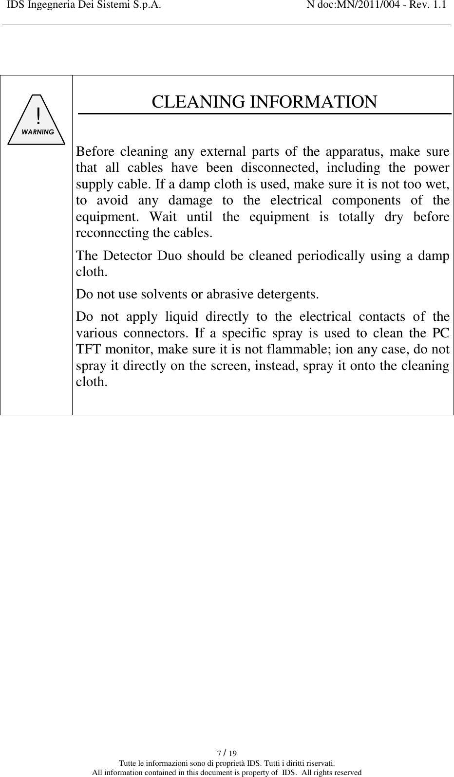
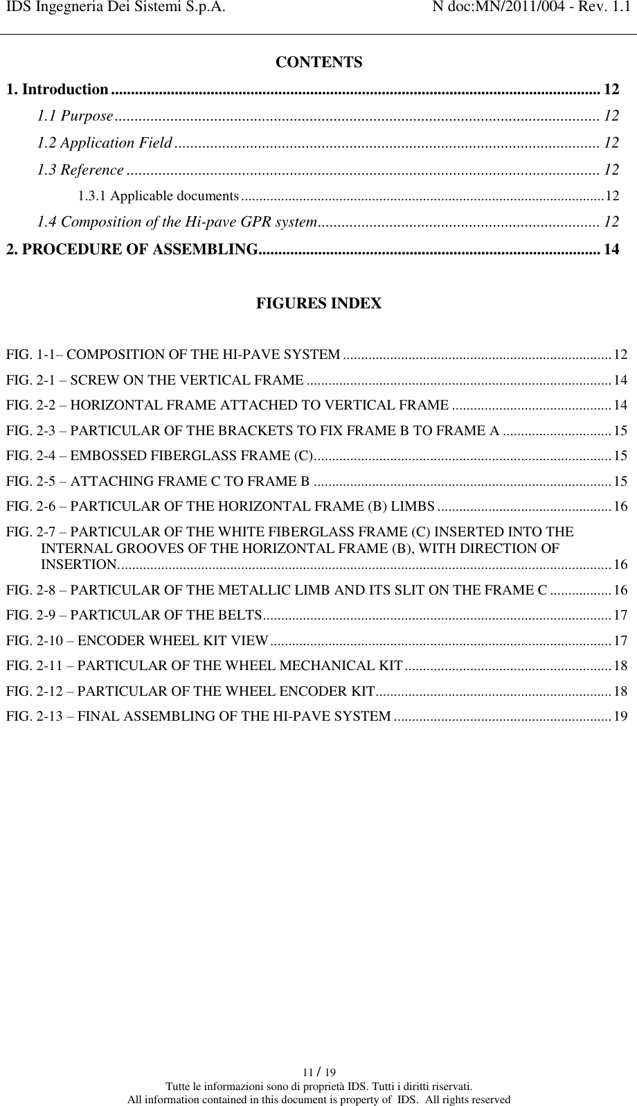
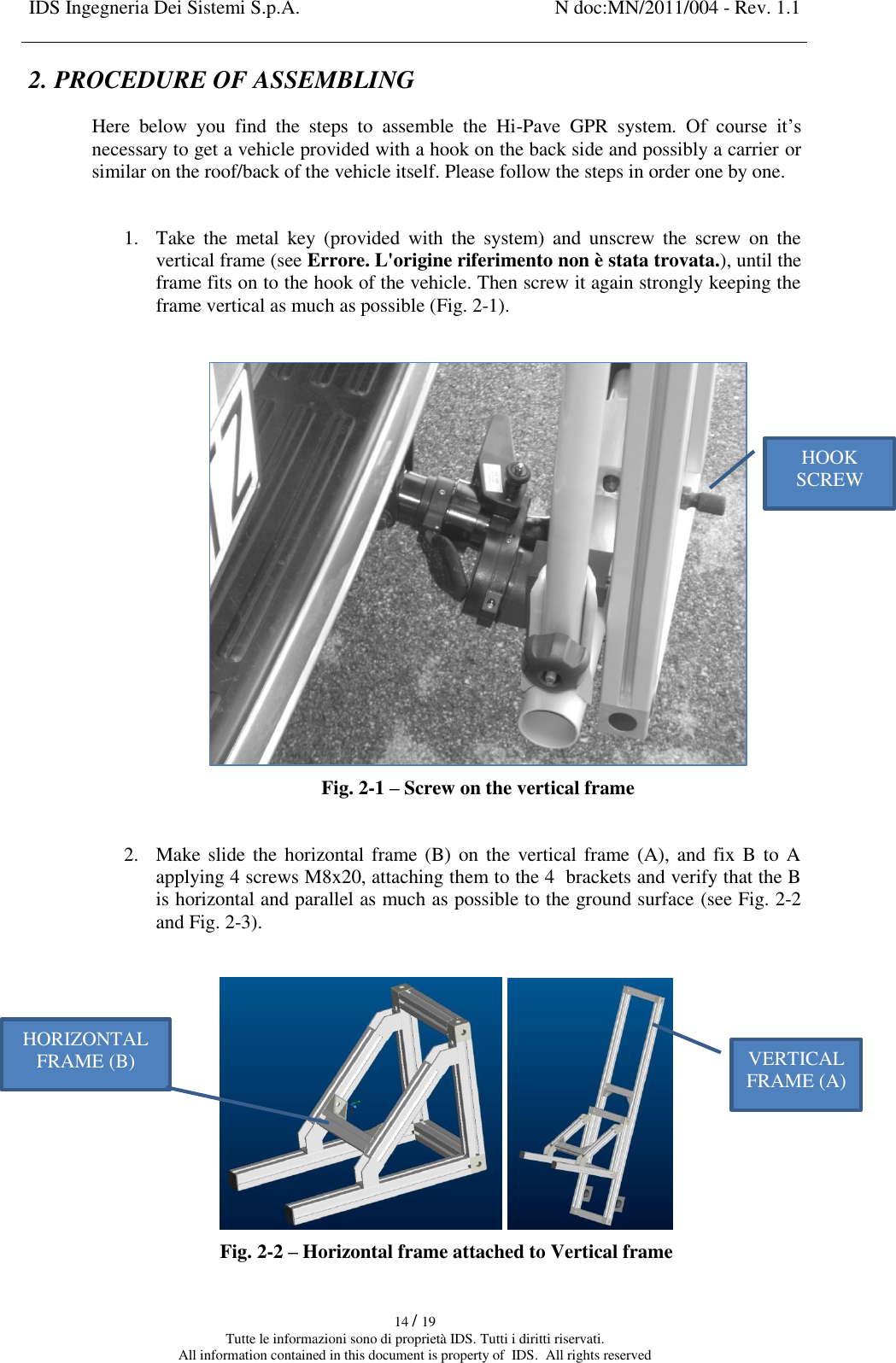
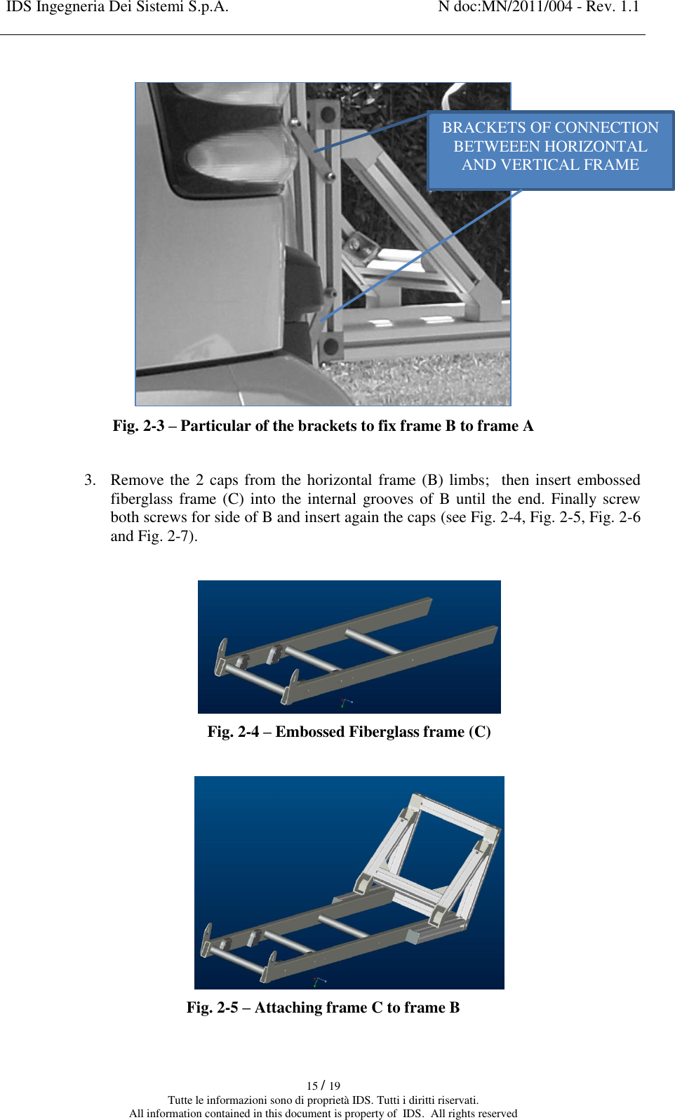
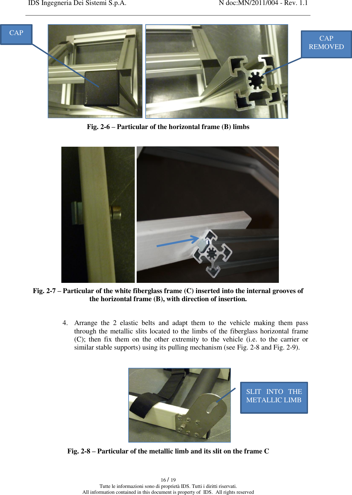
![IDS Ingegneria Dei Sistemi S.p.A. N doc:MN/2011/004 - Rev. 1.1 12 / 19 Tutte le informazioni sono di proprietà IDS. Tutti i diritti riservati. All information contained in this document is property of IDS. All rights reserved 1. INTRODUCTION 1.1 Purpose This manual explains the procedure of assembling the Hi-Pave GPR system in all its parts. Ids Hi-Pave system uses HR1000 and/or the HR2000 antennas; the model HR2000NA only is allowed to operate in the US and Canadian markets. 1.2 Application Field This system is dedicated for pavement applications on the asphalt and concrete roads. The most common application is detecting the thickness of asphalt layers, within the first meter of depth. 1.3 Reference The applicable versions of the following documents are the ones officially released at the time of the emission of this present document. 1.3.1 Applicable documents [AD1] - MN_2008_031_11 – K2 Fast Wave User Manual 1.4 Composition of the Hi-pave GPR system Here below you find the parts of the Hi-pave system: Fig. 1-1– Composition of the Hi-Pave system ENCODER VERTICAL FRAME SLIDING CART ELASTIC BELT HORN ANTENNA FIBERGLASS HORIZONTAL FRAME HOOK SCREW](https://usermanual.wiki/IDS-GeoRadar-s-r-l/HR2000NA/User-Guide-1624103-Page-12.png)