IDS GeoRadar s r l IBIS-KU-ETH IBIS Sensor Unit User Manual
IDS GeoRadar Srl IBIS Sensor Unit
UserManual.wiki
>
IDS GeoRadar s r l
>
IBIS KU ETH User Manual
User Manual
Navigation menu
Upload a User Manual
Namespaces
Wiki Guide
HTML
PDF
Info
Views
User Manual
Discussion / Help
Navigation
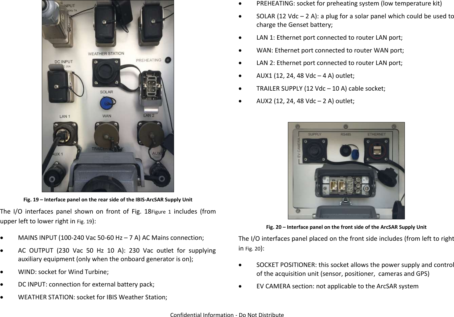
![2 ABOUT THE MANUAL IDS GeoRadar S.r.l. Confidential Information - Do Not Distribute MNG/2017/0016 Rev 1.0 7/ 78 2.3 Glossary and acronyms 2.3.1 Acronyms AC Access Point DEM Digital Elevation Model FMCW Frequency linearly Modulated Continuous Wave GPS Global Positioning System IBIS Image By Interferometric Survey LED Light Emitting Diode LoS Line of Sight LS Linear Scanner PoE Power over Ethernet PSU Power Supply Unit SAR Synthetic Aperture Radar SNR Signal to Noise Ratio SU Subscriber Unit USB Universal Serial Bus 2.4 Reference 2.4.1 Bibliography [BD1] MNG/2016/0009 – IBIS Controller v.04.02 – User Manual [BD2] MNG/2016/0001 – IBIS Guardian v. 03.02 – User Manual [BD3] MN/2014/062 (IDS) – Eagle-Vision Camera - Installation Guide [BD4] MNG/2016/0017 - IBIS-ROVER System – Maintenance and Repair Guide 2.4.2 1.6.2 Definitions Pixel: area of resolution used in the IBIS-ArcSAR system. Radial displacement: displacement of the range bin or the pixel along the direction joining the Range bin or pixel to the IBIS system i.e. along the LoS.](https://usermanual.wiki/IDS-GeoRadar-s-r-l/IBIS-KU-ETH/User-Guide-3592497-Page-7.png)
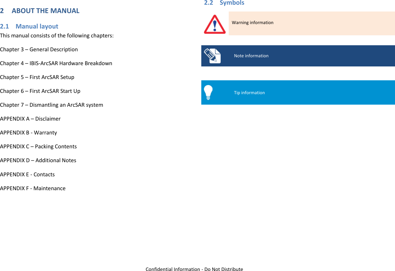
![5 FIRST ArcSAR SETUP IDS GeoRadar S.r.l. Confidential Information - Do Not Distribute MNG/2017/0016 Rev 1.0 57/ 78 Fig. 122 – Hikvision login page insert admin as User Name and ibis12345 as password and click Login (Fig. 122); select Configuration and on the column on the left column select Network; insert the new IP address, Selection mask and Default gateway (Fig. 123); Fig. 123 – Hikvision configuration page close Internet Explorer; change the IP address of Pointing Camera in IBIS Controller settings. For any further details refer to IBIS Controller User Manual [BD1]. 5.18.3 Weather Station internal Data Logger board IP address To change the IP address of the internal Weather Station board, open the browser and access the related application webpage. The default IP address is 10.0.0.104. In the WeatherLink IP Configuration page, tick the field Use the following IP Address and assign the desired IP Address with the related Selection Mask and Default Gateway. Do not change anything in the right part of the window. (Fig. 124).](https://usermanual.wiki/IDS-GeoRadar-s-r-l/IBIS-KU-ETH/User-Guide-3592497-Page-57.png)
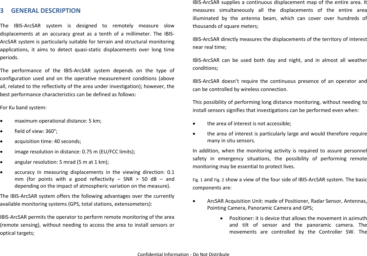
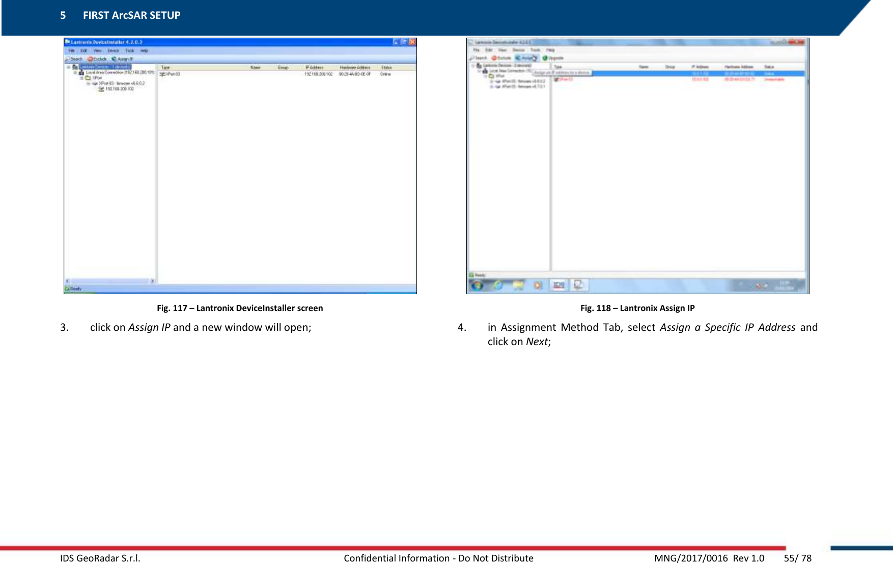
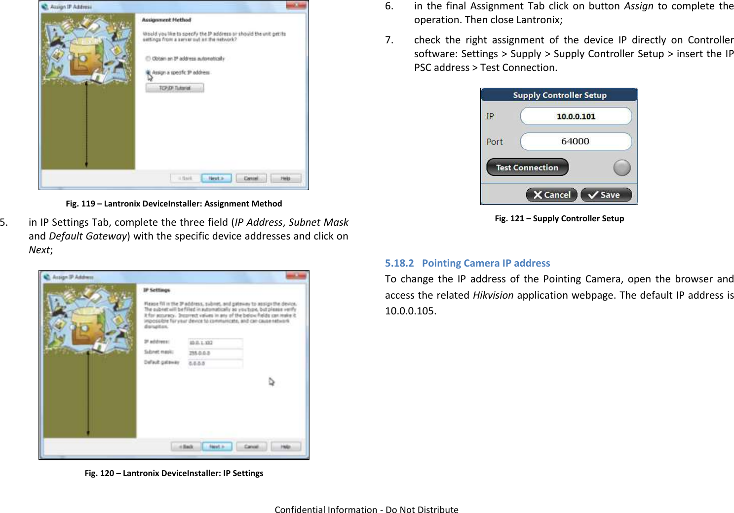
![Confidential Information - Do Not Distribute Fig. 124 – WeatherLink IP configuration page Press Save IP Settings to confirm and close Internet Explorer. Change the IP address of Weather Station in IBIS Controller settings. For any further details refer to IBIS Controller User Manual [BD1]. 5.18.4 Wi-Fi Radio IP address To change the IP address of the Wi-Fi radios, open the browser and access the related AirOS application webpage. The default IP address is 10.0.0.106. Fig. 125 – AirOS login page insert ubnt as User Name and Password and click Login (Fig. 125); select Network on the upper taskbar to access the network configuration page; Fig. 126 – AirOS taskbar set the Network Mode as Bridge; set the Configuration Mode as Simple; in Management Network Settings, tick Static in the Management IP Address; change the IP address, Subnet mask and Default gateway, modifying the related fields (Fig. 127); Fig. 127 – AirOS: Management Network Settings click on Change button, placed at the lower right corner of the screen to save the settings and close the AirOS application. 5.18.5 ArcSAR Laptop IP address To change the IP address of the CF31 ArcSAR Laptop, follow the steps below:](https://usermanual.wiki/IDS-GeoRadar-s-r-l/IBIS-KU-ETH/User-Guide-3592497-Page-58.png)
![5 FIRST ArcSAR SETUP IDS GeoRadar S.r.l. Confidential Information - Do Not Distribute MNG/2017/0016 Rev 1.0 59/ 78 - go on the Windows taskbar; - right click on the Network icon; - access Open Network and Sharing Center; - open the Local Area Connection link; - open Properties; - select Internet Protocol Version 4; - click on Properties; - tick Use the following IP address and insert the new IP address, Subnet mask and Default gateway. Then click OK - reboot the computer 5.19 Controller General Settings Before starting the setup for a new IBIS-ArcSAR session, it is recommended to take possession of: Digital Terrain Model (DTM) of the scenario to monitor. IBIS Controller accepts following file formats: .dxf, Shapefiles, .xyz or ASCII grid (.txt); the EPSG code which is a unique value used to unambiguously identify projected, unprojected, and local spatial coordinate system definitions; the IP address of IBIS Guardian software and the type of data transfer (TCP or FTP). For any further details, please refer to the IBIS Controller User Manual [BD1]. 5.20 End of the ArcSAR First Setup To complete the first setup, turn off the PSU and GENSET Isolation Point switches](https://usermanual.wiki/IDS-GeoRadar-s-r-l/IBIS-KU-ETH/User-Guide-3592497-Page-59.png)
![5 FIRST IBIS-ArcSAR START UP IDS GeoRadar S.r.l. Confidential Information - Do Not Distribute MNG/2017/0016 Rev 1.0 67/ 78 6.6 Wind Turbine Setup If the Wind Turbine has been installed as optional, repeat the setup steps as described in the Paragraph 5.14. 6.7 Panoramic Camera Setup To supply the Panoramic Camera, it’s necessary to open the PSU door and turn on the CAMERA switch (Fig. 152). Fig. 152 – Turning the CAMERA switch on (PSU Control module) For the configuration of the Panoramic Camera during a new Controller session wizard, please refer to the IBIS Controller User Manual [BD1]. 6.8 Laptop Starting 1. open the Laptop sliding drawer placed under the PSU modules; 2. unscrew the knob on the right and pull out the sliding drawer; Fig. 153 – CF31 laptop with cables connected 3. supply the Laptop turning on the PC switch on the Control Module Fig. 154 – PC Switch on Control Module 4. the Laptop will be automatically turned on. Wait the loading of the Operating System and the loading of the IBIS Controller software. In any case the software can be run clicking on its desktop icon.](https://usermanual.wiki/IDS-GeoRadar-s-r-l/IBIS-KU-ETH/User-Guide-3592497-Page-67.png)
![Confidential Information - Do Not Distribute 6.9 Session starting Once the instrument with all its peripherals is installed according to instructions, it is ready to be used. The following list describes the operations requires to start up and use IBIS-ArcSAR: 1. make sure that SENSOR and POSITIONER switches are turned on; 2. make sure GPS switch is turned on; 3. turn on the other switches if the related components are present in the system configuration. Remind that if the CAMERA and WIFI switches are turned on, the related plugs are supplied by Power-over-Ethernet. At this point, a new session can be created on the IBIS Controller application and the instrument can be used following the instructions provided in the IBIS Controller User Manual [BD1]. ArcSAR POSITION SURVEYING The IBIS-ArcSAR is provided with the integrated GPS. The surveying of the ArcSAR position will be performed automatically during a new session wizard. It is mandatory to set the EPSG code in the Controller Settings. The ArcSAR position can also be evaluated surveying the two little sliding plates placed at the ends of the Positioner (Fig. 155) and then calculating the middle point of the Positioner. This surveying has to be done with the Positioner at 0° azimuth (Scanner parallel to the shorter trailer side). Fig. 155 – Sliding plates to survey Positioner 7 DISMANTLING AN IBIS-ArcSAR SYSTEM 7.1 Actions on IBIS Controller and on ArcSAR Laptop Stop the running Controller session, clicking on the STOP button (refer to the IBIS Controller User Manual [BD1]); close the IBIS Controller application; the software will ask to move the IBIS-ArcSAR Positioner to the Transport Mode. It is mandatory to click Yes. Wait the end of the movement of the ArcSAR Positioner; During the transportation of the IBIS-ArcSAR, the Positioner has to be set on Transport mode ().](https://usermanual.wiki/IDS-GeoRadar-s-r-l/IBIS-KU-ETH/User-Guide-3592497-Page-68.png)

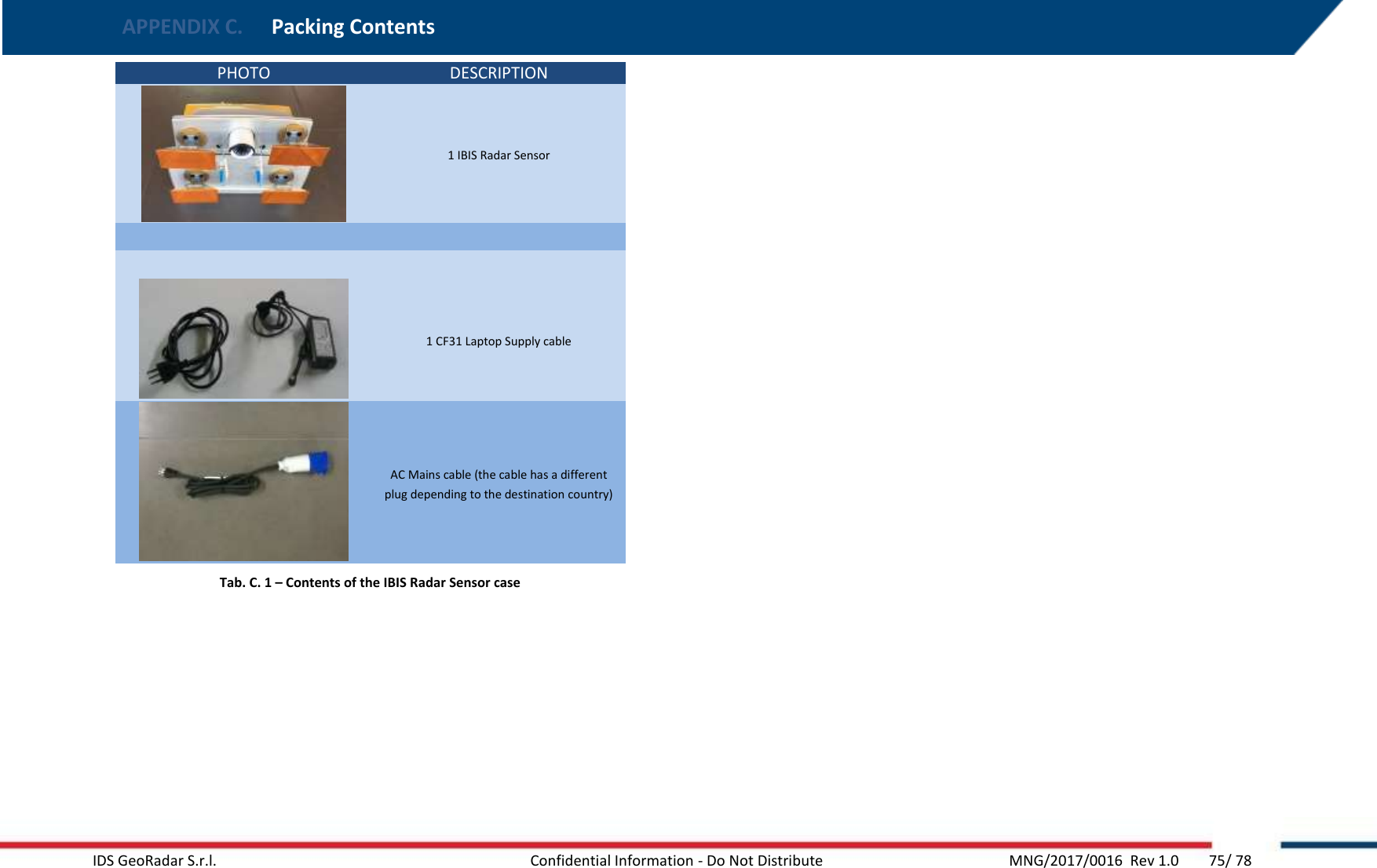
![Confidential Information - Do Not Distribute APPENDIX C PACKING CONTENTS IBIS ArcSAR Acquisition Unit Box: Wooden packaging - liftable with fork truck - (size: 184 x 113 x 249 (length [cm] x width [cm] x height [cm] )) and total weight, when fully packed, of 495 kg). This box contains following parts: The ArcSAR Positioner; IBIS Supply Unit Box Wooden packaging - liftable with fork truck - (size: 166 x 198 x 142 (length [cm] x width [cm] x height [cm] )) and total weight, when fully packed, of 1200 kg). This box contains following parts: The ArcSAR Supply Unit. IBIS Trailer Unit Box Wooden container - liftable with fork truck - (size 433 x 227 x 131 (length [cm] x width [cm] x height [cm] )). This box contains following parts: The ArcSAR Trailer; The CF31 ArcSAR computer; The metallic pole to install IBIS ArcSAR accessories; The Generator Solar Panel and its metallic frame; IBIS ArcSAR standard cables (see Paragraph 4.5); IBIS ArcSAR standard spare parts (depending by the Customer purchase); The Wi-Fi radios (if they have been purchased as optional items); The Weather Station Package (if it has been purchased as optional item); The Wind Turbine Installation Kit and its metallic pole (if it has been purchased as optional item); The IBIS Radar Sensor case (Fig. C. 1) (size 80 x 50 x 30 cm and total weight - when packed - of 28 kg). This case contains the following list of materials (Tab. C. 1): Fig. C. 1 – IBIS Radar Sensor case](https://usermanual.wiki/IDS-GeoRadar-s-r-l/IBIS-KU-ETH/User-Guide-3592497-Page-74.png)
![Confidential Information - Do Not Distribute APPENDIX F MAINTENANCE About the maintenance of IBIS-ArcSAR please refer to the Maintenance and Repair Guide [BD4].](https://usermanual.wiki/IDS-GeoRadar-s-r-l/IBIS-KU-ETH/User-Guide-3592497-Page-78.png)