IDS GeoRadar s r l IBIS-KU-ETH IBIS Sensor Unit User Manual
IDS GeoRadar Srl IBIS Sensor Unit
User Manual

MNG/2017/0016
Rev 1.0
IBIS-ArcSAR
User manual

INDEX
IDS GeoRadar S.r.l. Confidential Information - Do Not Distribute MNG/2017/0016 Rev 1.0 2/78
INDEX
1 INTRODUCTION .............................................................................................................................................................................................................................. 5
1.1 Purpose ....................................................................................................................................................................................................................... 5
1.2 Application field .......................................................................................................................................................................................................... 5
2 ABOUT THE MANUAL ..................................................................................................................................................................................................................... 6
2.1 Manual layout ............................................................................................................................................................................................................. 6
2.2 Symbols ....................................................................................................................................................................................................................... 6
2.3 Glossary and acronyms ............................................................................................................................................................................................... 7
2.4 Reference .................................................................................................................................................................................................................... 7
3 GENERAL DESCRIPTION .................................................................................................................................................................................................................. 8
4 IBIS-ArcSAR HARDWARE BREAKDOWN ........................................................................................................................................................................................ 11
4.1 ArcSAR Trailer ........................................................................................................................................................................................................... 11
4.2 ArcSAR Acquisition Unit ............................................................................................................................................................................................ 11
4.3 ArcSAR Supply Unit ................................................................................................................................................................................................... 15
4.4 Pole ........................................................................................................................................................................................................................... 21
4.5 Additional items ........................................................................................................................................................................................................ 22
4.6 Solar Panels ............................................................................................................................................................................................................... 23
4.7 Wind Turbine (optional) ........................................................................................................................................................................................... 23
4.8 Weather Station (optional) ....................................................................................................................................................................................... 23
4.9 Wi-Fi Link (optional) .................................................................................................................................................................................................. 24
4.10 Low temperature kit (optional) ................................................................................................................................................................................ 25
5 FIRST ArcSAR SETUP ..................................................................................................................................................................................................................... 26

1 INTRODUCTION
IDS GeoRadar S.r.l. Confidential Information – Do Not Distribute MNG/2017/0016 Rev 1.0 3/ 78
5.1 Unpacking the wooden boxes .................................................................................................................................................................................. 26
5.2 Supply Unit on the trailer deck ................................................................................................................................................................................. 26
5.3 Acquisition Unit on the trailer deck .......................................................................................................................................................................... 29
5.4 Pole on the Supply Unit ............................................................................................................................................................................................ 31
5.5 IBIS Accessories on Pole ............................................................................................................................................................................................ 32
5.6 Wind Turbine and Pole Installation and Setup ......................................................................................................................................................... 39
5.7 Trailer cable connection ........................................................................................................................................................................................... 45
5.8 IBIS Sensor Setup ...................................................................................................................................................................................................... 46
5.9 Panoramic Camera Setup ......................................................................................................................................................................................... 47
5.10 Supply Unit and Acquisition Unit Connections Setup ............................................................................................................................................... 47
5.11 Safety Electrical devices Setup ................................................................................................................................................................................. 47
5.12 Generator First Setup ............................................................................................................................................................................................... 48
5.13 Turning on the system .............................................................................................................................................................................................. 51
5.14 Green module first setup .......................................................................................................................................................................................... 51
5.15 ArcSAR Sensor first set up ......................................................................................................................................................................................... 52
5.16 ArcSAR Positioner first set up ................................................................................................................................................................................... 53
5.17 ArcSAR Laptop first setup ......................................................................................................................................................................................... 53
5.18 ArcSAR IP addresses configuration ........................................................................................................................................................................... 54
5.19 Controller General Settings ...................................................................................................................................................................................... 59
5.20 End of the ArcSAR First Setup ................................................................................................................................................................................... 59
6 FIRST IBIS-ArcSAR START UP ......................................................................................................................................................................................................... 60
6.1 Park the IBIS-ArcSAR ................................................................................................................................................................................................. 60
6.2 Disconnect the IBIS-ArcSAR from the truck .............................................................................................................................................................. 60
Confidential Information - Do Not Distribute
6.3 Hydraulic Jacks Setup ................................................................................................................................................................................................ 62
6.4 Power Supply Unit setup .......................................................................................................................................................................................... 64
6.5 Generator setup ........................................................................................................................................................................................................ 66
6.6 Wind Turbine Setup .................................................................................................................................................................................................. 67
6.7 Panoramic Camera Setup ......................................................................................................................................................................................... 67
6.8 Laptop Starting.......................................................................................................................................................................................................... 67
6.9 Session starting ......................................................................................................................................................................................................... 68
7 DISMANTLING AN IBIS-ArcSAR SYSTEM ....................................................................................................................................................................................... 68
7.1 Actions on IBIS Controller and on ArcSAR Laptop .................................................................................................................................................... 68
7.2 Actions on the ArcSAR Supply Unit ........................................................................................................................................................................... 69
7.3 Actions on the Trailer jacks ....................................................................................................................................................................................... 69
7.4 Get ArcSAR ready to drive ........................................................................................................................................................................................ 69
APPENDIX A Disclaimer ................................................................................................................................................................................................................... 70
APPENDIX B Warranty ..................................................................................................................................................................................................................... 72
APPENDIX C Packing Contents ........................................................................................................................................................................................................ 74
APPENDIX D Additional Notes ......................................................................................................................................................................................................... 76
Authorization of utilization – national restrictions ........................................................................................................................................................................ 76
CE Marking ...................................................................................................................................................................................................................................... 76
APPENDIX E Contacts ...................................................................................................................................................................................................................... 77
APPENDIX F Maintenance ............................................................................................................................................................................................................... 78

1 INTRODUCTION
IDS Ingegneria dei Sistemi S.p.A. Confidential Information - Do Not Distribute MNG/2017/0016 Rev 1.0 5/ 78
1 INTRODUCTION
This document describes the IBIS-ArcSAR system, and particularly refers to
the concepts the user should learn before initiating the utilization of this
device. Therefore we recommend to read the entire document before
starting the system.
If technical assistance is required, please use the contact numbers provided
on the Appendix of this manual.
The information contained in this document is confidential and may not be
used, published or redistributed without the prior consent of IDS Georadar
Srl.
1.1 Purpose
Reading this document will provide all the necessary knowledge to install
and maintain the IBIS-ArcSAr system. It particularly presents a step by step
procedure to install the system, information for a safe use of the system
and instructions for its general maintenance.
1.2 Application field
This document applies to the installation of the IBIS system in ArcSAR
configuration and its use in the field for monitoring of quasi static
phenomena.

Confidential Information - Do Not Distribute
2 ABOUT THE MANUAL
2.1 Manual layout
This manual consists of the following chapters:
Chapter 3 – General Description
Chapter 4 – IBIS-ArcSAR Hardware Breakdown
Chapter 5 – First ArcSAR Setup
Chapter 6 – First ArcSAR Start Up
Chapter 7 – Dismantling an ArcSAR system
APPENDIX A – Disclaimer
APPENDIX B - Warranty
APPENDIX C – Packing Contents
APPENDIX D – Additional Notes
APPENDIX E - Contacts
APPENDIX F - Maintenance
2.2 Symbols
Warning information
Note information
Tip information

2 ABOUT THE MANUAL
IDS GeoRadar S.r.l. Confidential Information - Do Not Distribute MNG/2017/0016 Rev 1.0 7/ 78
2.3 Glossary and acronyms
2.3.1 Acronyms
AC Access Point
DEM Digital Elevation Model
FMCW Frequency linearly Modulated Continuous Wave
GPS Global Positioning System
IBIS Image By Interferometric Survey
LED Light Emitting Diode
LoS Line of Sight
LS Linear Scanner
PoE Power over Ethernet
PSU Power Supply Unit
SAR Synthetic Aperture Radar
SNR Signal to Noise Ratio
SU Subscriber Unit
USB Universal Serial Bus
2.4 Reference
2.4.1 Bibliography
[BD1] MNG/2016/0009 – IBIS Controller v.04.02 – User Manual
[BD2] MNG/2016/0001 – IBIS Guardian v. 03.02 – User Manual
[BD3] MN/2014/062 (IDS) – Eagle-Vision Camera - Installation Guide
[BD4] MNG/2016/0017 - IBIS-ROVER System – Maintenance and
Repair Guide
2.4.2 1.6.2 Definitions
Pixel: area of resolution used in the IBIS-ArcSAR system.
Radial displacement: displacement of the range bin or the pixel along the
direction joining the Range bin or pixel to the IBIS system i.e. along the LoS.
Confidential Information - Do Not Distribute
3 GENERAL DESCRIPTION
The IBIS-ArcSAR system is designed to remotely measure slow
displacements at an accuracy great as a tenth of a millimeter. The IBIS-
ArcSAR system is particularly suitable for terrain and structural monitoring
applications, it aims to detect quasi-static displacements over long time
periods.
The performance of the IBIS-ArcSAR system depends on the type of
configuration used and on the operative measurement conditions (above
all, related to the reflectivity of the area under investigation); however, the
best performance characteristics can be defined as follows:
For Ku band system:
maximum operational distance: 5 km;
field of view: 360°;
acquisition time: 40 seconds;
image resolution in distance: 0.75 m (EU/FCC limits);
angular resolution: 5 mrad (5 m at 1 km);
accuracy in measuring displacements in the viewing direction: 0.1
mm (for points with a good reflectivity – SNR > 50 dB – and
depending on the impact of atmospheric variation on the measure).
The IBIS-ArcSAR system offers the following advantages over the currently
available monitoring systems (GPS, total stations, extensometers):
IBIS-ArcSAR permits the operator to perform remote monitoring of the area
(remote sensing), without needing to access the area to install sensors or
optical targets;
IBIS-ArcSAR supplies a continuous displacement map of the entire area. It
measures simultaneously all the displacements of the entire area
illuminated by the antenna beam, which can cover over hundreds of
thousands of square meters;
IBIS-ArcSAR directly measures the displacements of the territory of interest
near real time;
IBIS-ArcSAR can be used both day and night, and in almost all weather
conditions;
IBIS-ArcSAR doesn’t require the continuous presence of an operator and
can be controlled by wireless connection.
This possibility of performing long distance monitoring, without needing to
install sensors signifies that investigations can be performed even when:
the area of interest is not accessible;
the area of interest is particularly large and would therefore require
many in situ sensors.
In addition, when the monitoring activity is required to assure personnel
safety in emergency situations, the possibility of performing remote
monitoring may be essential to protect lives.
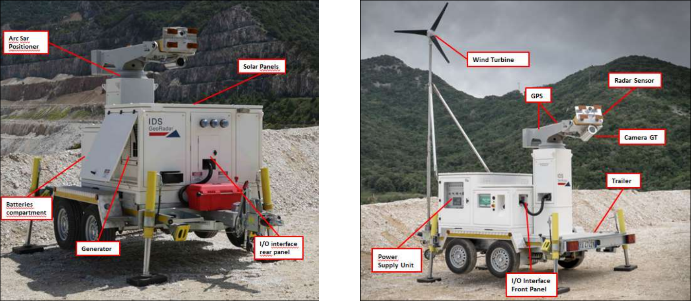
Fig. 1 and Fig. 2 show a view of the four side of IBIS-ArcSAR system. The basic
components are:
ArcSAR Acquisition Unit: made of Positioner, Radar Sensor, Antennas,
Pointing Camera, Panoramic Camera and GPS;
Positioner: it is device that allows the movement in azimuth
and tilt of sensor and the panoramic camera. The
movements are controlled by the Controller SW. The

3 GENERAL DESCRIPTION
IDS GeoRadar S.r.l. Confidential Information - Do Not Distribute MNG/2017/0016 Rev 1.0 9/ 78
positioner is able to rotate within 360°. The radar view can
therefore be 360° wide.
Radar Sensor: it generates, transmits and receives the
electromagnetic signal. The Radar Sensor is installed at the
edge of the positioner arm. The movement of the Radar
Sensor around the positioner permits the utilization of the
ArcSAR technique, which obtains a 3D image of the
scenario;
Antennas: proper antennas are required to make the Radar
Sensor properly transmitting and receiving RF signals;
Pointing Camera: mounted right over the Radar Sensor, it
helps to easily define the area of interest. A video
streaming is in fact integrated in the Controller Software to
get a real time feedback of the Radar current pointing
direction during the session setup.
Panoramic Camera: installed below the radar trolley, it
provides 360° high-resolution geocoded images of the
scenario;
GPS: to automatically retrieve the information needed for
the geocoding (Radar position and bearing);
ArcSAR Supply Unit: this module is in charge of giving power supply
and control to the Acquisition Unit and to other optional devices
such as WIFI antenna and weather station; It is composed of:
Laptop PC: it is equipped with the system management
software (IBIS Controller Software). This is used to setup
the acquisition parameters, store the data and transmit
them to the control room;
Battery pack: this is the main source for supplying the
Acquisition System and all the other devices;
Generator: it is the main source of power used to recharge
the battery pack when connection to the grid is not
available. It can be configured to automatically start when
required;
ArcSAR Trailer: it permits the mobilization of the IBIS-
ArcSAR and gives extreme stability to the Acquisition Unit
during the monitoring session thanks to hydraulic jacks.
Integrated Solar Panels: for recharging the battery pack
therefore reducing the generator running time;
The optional components are:
Wind turbine: for recharging the battery pack therefore
reducing the generator running time;
Weather Station: it provides information about the
atmospheric conditions;
Wi-Fi Bridge: it permits data transmission from IBIS-ArcSAR
to the Control Room;
Low temperature kit: it allows the IBIS-ArcSAR operation in
extremely cold environments;
Confidential Information - Do Not Distribute
Fig. 1 – IBIS-ArcSAR system (rear and right side)
Fig. 2 – IBIS-ArcSAR system (front and left side)
4 IBIS-ArcSAR HARDWARE BREAKDOWN
IDS GeoRadar S.r.l. Confidential Information - Do Not Distribute MNG/2017/0016 Rev 1.0 11/ 78
4 IBIS-ArcSAR HARDWARE BREAKDOWN
This section of the manual provides a detailed description of the
components making up IBIS-ArcSAR system:
The system configuration depends on the selected purchase options, the
system may not include some of the items specified below.
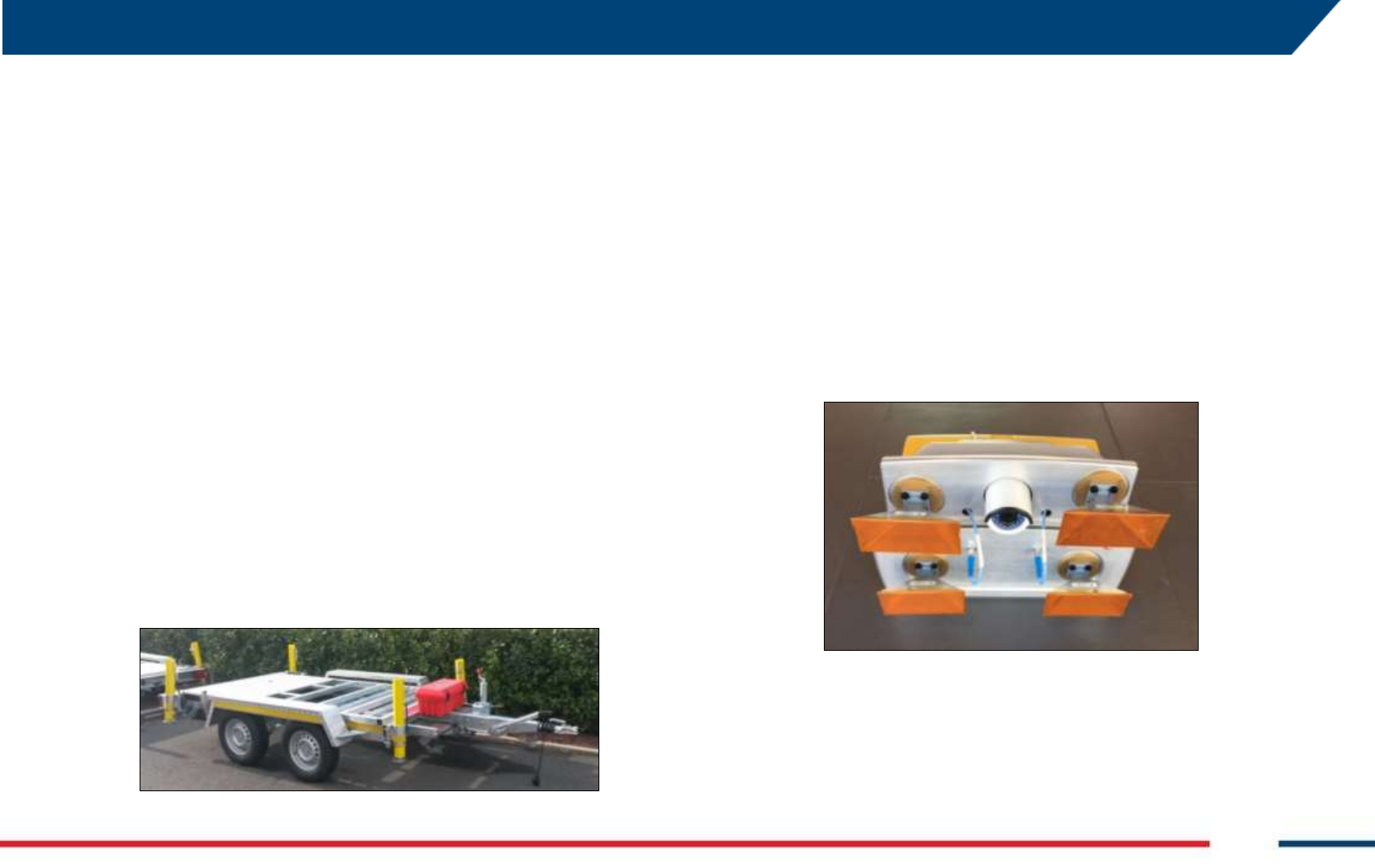
4.1 ArcSAR Trailer
The ArcSAR Trailer (Fig. 3) is the basis where the IBIS-ArcSAR Base is set. It is
provided with a hook to tow the trailer with a vehicle. At every corner there
is a hydraulic support legs (or jacks) whose task is ensuring the stability of
the trailer during IBIS-ArcSAR operation. Trailer is equipped with
mechanical brakes plus a hand brake for parking. Next to the wheels four
yellow chock levels are provided to increase the working security when the
trailer is parked.
The supplying of the trailer supports is provided by a cable to connect to
the main I/O interface panel, placed on the rear side of ArcSAR Supply Unit.
A battery cut-off is provided to isolate the supplying of hydraulic supports
(Fig. 28).
Fig. 3 - View of the ArcSAR Trailer
The trailer is provided with a car connector to supply the rear positioning
lights of the trailer.
4.2 ArcSAR Acquisition Unit
This system is made of Positioner, Radar Sensor, Antennas, Pointing
Camera, Camera GT and GPS
4.2.1 IBIS Radar Sensor
The IBIS Radar Sensor is a unit containing all the parts for the generation,
transmission, reception and acquisition of the radar signal. The Radar
Sensor is shown in Fig. 4 and can be seen as a yellow box.
Fig. 4 – IBIS Radar Sensor front view
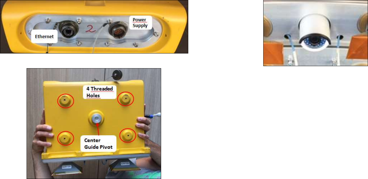
The Radar Sensor has the following interfaces (see Fig. 5 and Fig. 6):
Ethernet type and Supply sockets on the case back-side;
#4 threaded holes and a central pivot on the case bottom-side to fix
the sensor to Positioner trolley;
Confidential Information - Do Not Distribute
Fig. 5 – Back view of the Radar Sensor
Fig. 6 – Bottom view of the Radar Sensor
4.2.2 Radar Sensor Pointing Camera
The Pointing Camera is used to easily define the borders of the area to
cover with IBIS monitoring. This action is performed during the Controller
session wizard, where the user has to set manually the limits of the
scenario. The Pointing Camera provides a real-time streaming to the user
therefore giving a precise feedback on the actual radar pointing direction.
Pointing Camera is installed on the top cover of the Radar Sensor (Fig. 7) and
it is automatically supplied by the Positioner. Pointing Camera connections
consist of an Ethernet wire and a power wire (12Vdc).
Fig. 7 – ArcSAR Pointing Camera
4.2.3 Antennas (Ku band)
The Ku band IBIS-ArcSAR system is provided with four IBIS-ANT7 antennas
installed at slightly different elevations operating in vertical polarization.
The combination of four antennas installed at different elevations simulates
the vertical movement of the sensor, thus allowing the DEM creation.
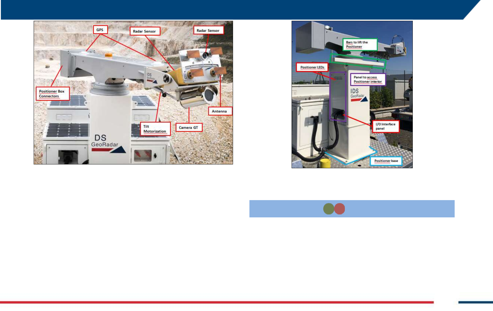
4.2.4 Positioner
The Positioner (Fig. 8) is equipped of 2 motorizations: the tilt, which is used
to facilitate radar pointing and the azimuth, which is used to perform
ArcSAR scans (radial).
4 IBIS-ArcSAR HARDWARE BREAKDOWN
IDS GeoRadar S.r.l. Confidential Information - Do Not Distribute MNG/2017/0016 Rev 1.0 13/ 78
Fig. 8 – Positioner top part
Tilt: Radar sensor tilt can range between +/-25° with an accuracy of
0.1°;
Azimuth: the main horizontal beam can rotate from -180° to +180°
with an accuracy of 0.01°;
Once tilt angle has been defined, ArcSAR scans with different angles can be
performed to extend or reduce the Radar Sensor field of view.
Fig. 9 – Positioner base
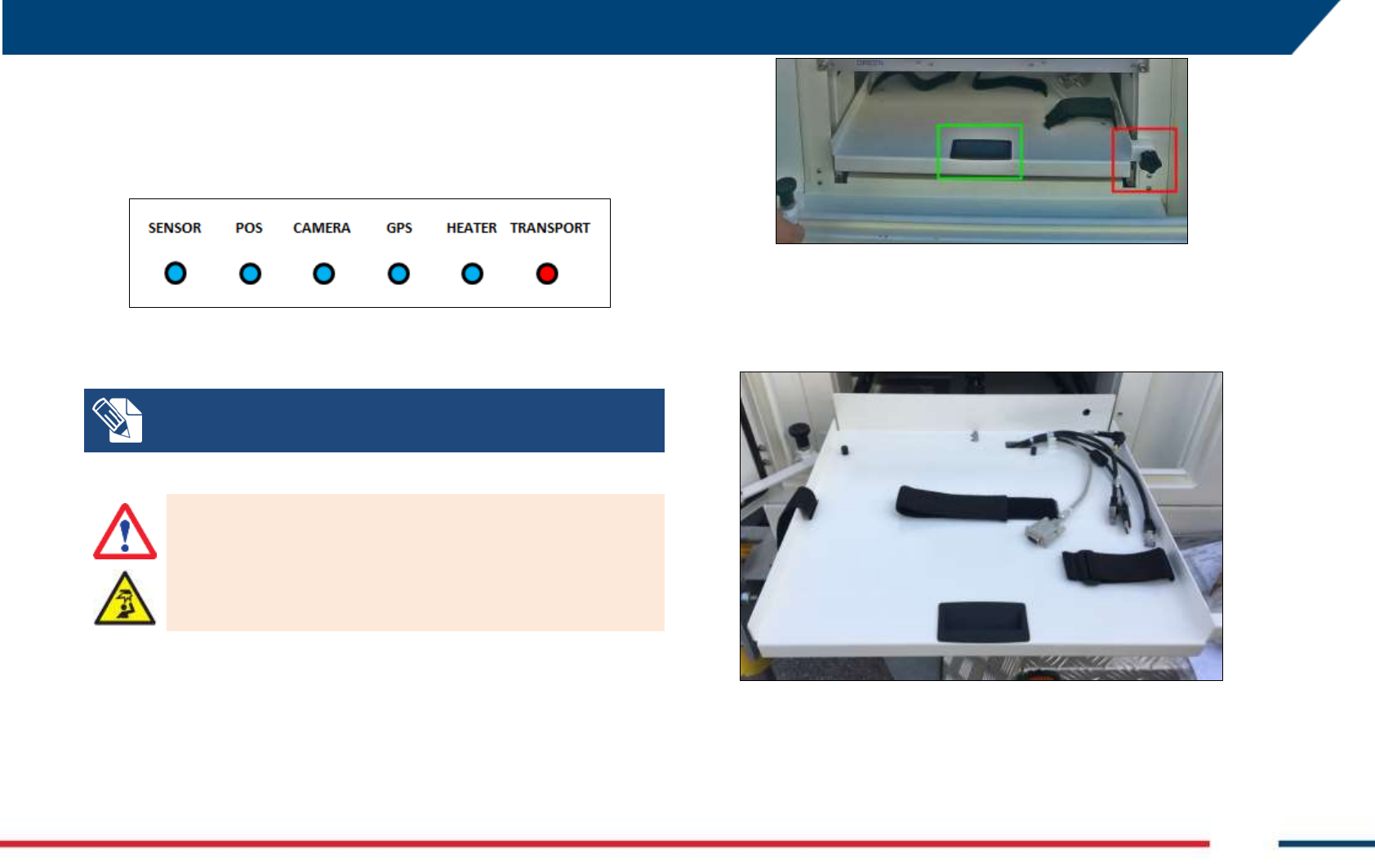
On the left side of the Positioner column, there are 6 LEDs (Fig. 9 –
Positioner base).
TRANSPORT
Transport mode
solid
Green when the system can
be moved. Red when the
system cannot be moved
Tab. 1 summarizes the meaning the LEDs.
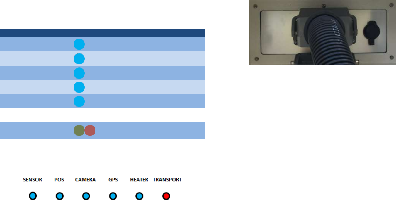
Confidential Information - Do Not Distribute
Label
Part
LED color
Meaning
SENSOR
Radar Sensor
solid
Related part powered
POS
Pointing motors
solid
Related part powered
CAMERA
Panoramic and
Pointing camera
solid
Related part powered
GPS
GPS
solid
Related part powered
HEATER
Low temperature
kit
solid
Related part powered
TRANSPORT
Transport mode
solid
Green when the system can
be moved. Red when the
system cannot be moved
Tab. 1 – Positioner LEDs meanings
Fig. 10 – Positioner LEDs
At the Positioner base there is an I/O Interface panel that included the
following sockets (Fig. 11):
Fig. 11 – I/O interface Positioner panel
SOCKET POSITIONER: this socket allows the power supply and control
of the acquisition unit (sensor, positioner, cameras and GPS)
Just below the rotating arm, two metal bars are provided to facilitate the
lifting and moving of the Positioner during ArcSAR first configuration.
The Positioner base has holes placed at every corner to allow the fixing of
the whole frame to the Trailer deck.
4.2.5 Panoramic Camera
Fixed below the radar trolley the camera (Fig. 14) rotates accordingly to the
positioner movement, providing 360° geocoded images of the scenario.
The camera combines long range surveillance capabilities with the
possibility to acquire 16 Mpixel pictures that are single panoramic views of
the entire scenario, arranged in layers of different image resolution. The
integration between the Panoramic Camera and the IBIS-ArcSAR provides
several additional features:
correlate the picture scenario with a given Guardian radar map, thus
enabling the visual recognition of moving areas;
These features are made possible thanks to the use of:
high resolution panoramic views of the scenario, obtained by
stitching several images in a single one. Views can be acquired on a
4 IBIS-ArcSAR HARDWARE BREAKDOWN
IDS GeoRadar S.r.l. Confidential Information - Do Not Distribute MNG/2017/0016 Rev 1.0 15/ 78
user request or automatically taken by the system following a user-
defined time schedule;
photo Georeference and link to digital terrain models. The camera
acquisition geometry is needed to enable the geocoding.
Fig. 14 – Camera fixed below the sensor trolley
4.2.6 GPS
During the Controller session setup allows to obtain the system position
and northing.
4.3 ArcSAR Supply Unit
This module is in charge of giving power supply and control to the
Acquisition Unit and to other optional devices as Wi-Fi radios and weather
station (both mounted on a dedicated pole) (Fig. 34 and ).
The ArcSAR Supply Unit allows the supplying and the control of all the
devices included in the ArcSAR Positioner. In addition, it allows the
communication between the field Laptop and the Control Room.
ArcSAR Supply Unit includes the Power Supply Unit with the ArcSAR battery
pack, the Laptop PC, the Generator set and the Solar Panels.
Weather Station, Wi-Fi and Generator Solar Panel can be installed on a
pole, whose casing is on the rear side of the ArcSAR Supply Unit.
On the bottom part of the Supply Unit side a holes grid is present to allow
the installation of the Supply Unit on the trailer deck.
4.3.1 Electrical modules
The PSU supplies electric power to the system. Its function is:
distribute power and signals to the ArcSAR Positioner, Radar Sensor
and other peripherals included in the system;
receive power from the Generator, Solar Panels or from AC Mains
supply and charge the batteries required to guarantee a continuous
power supply, even if a blackout occurs;
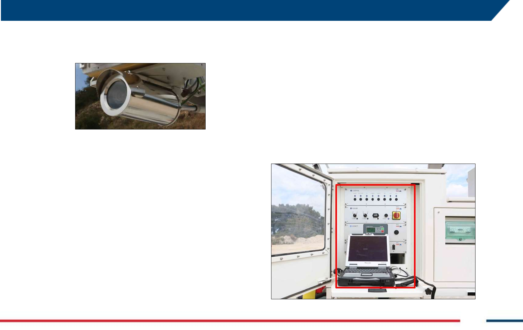
Fig. 12 – Power Supply Unit position on the left side of the IBIS-ArcSAR
Confidential Information - Do Not Distribute
The PSU is composed by drawers which are called modules, placed on the
left side of the ArcSAR Supply Unit. A front door gives access to them (Fig.
12). Description of the front side of each module follows here below.
Fig. 13 – Modules on the front side of PSU
Control module (Fig. 14): it contains electrical switches which permit
to supply (from left to right) Radar Sensor, Positioner, acquisition
Laptop PC, Panoramic Camera, Genset Module, GPS, AUX1 socket,
AUX2 socket;
Fig. 14 – Front side of the Control module
Power module (Fig. 15): it contains the following components (from
left to right):
AC Input switch: it permits to supply the system by AC voltage
from mains or Generator. The LED is lit up in blue when the
voltage is present.
DC Input switch: it permits to supply the system by DC current
provided by external source. The LED is lit up in blue when the
voltage is present.
Battery: this indicator shows the charge level of the batteries.
The LED is lit up in orange when the batteries are charging;
Enable switch: it permits to supply all the modules of the PSU;
ON/OFF Switch: it interrupts the power supplying of the
system, including the charging of the batteries;
Every time the system is shut down and then supplied again, it is always
necessary to press the enable switch in order to switch on the system
The DC Input switch has to be turned on when for example an external battery
pack is connected to the system. After connecting the external battery pack
and turning on the DC Input switch, the entire system automatically turns off
and it is necessary to press again the Enable switch to restore the system
4 IBIS-ArcSAR HARDWARE BREAKDOWN
IDS GeoRadar S.r.l. Confidential Information - Do Not Distribute MNG/2017/0016 Rev 1.0 17/ 78
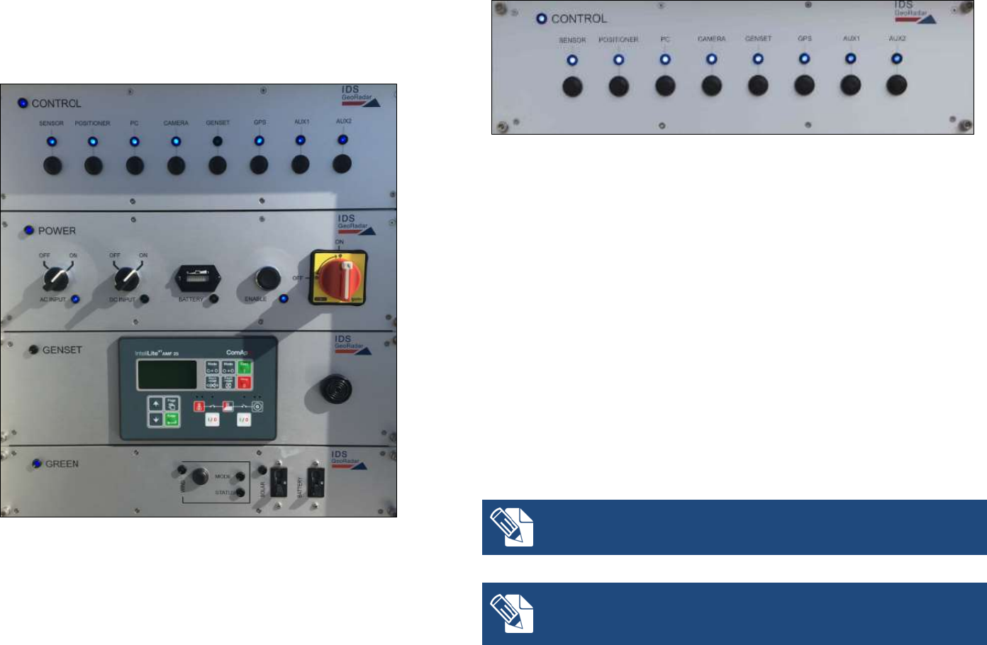
Fig. 15 – Front side of the Power module
Genset module (Fig. 16) is provided along with the integrated
generator: it contains the Generator control unit AMF25 which can
start or stop the generator and manage alarm and warning signals
from the generator sensors (e.g. lack of oil, empty tank, etc.). On the
right hand side (see Fig. 16) there is a horn which activates when
AMF25 alarm/warning is present; AMF25 is already set and ready to
communicate with the PSC board into the Control module;
Fig. 16 – Front side of the Genset module
Green module (Fig. 17) is associated to solar panels and wind turbine.
It contains following parts:
WIND: it includes the button to brake the wind turbine and the
LEDs to check the charging status and working mode
SOLAR: it includes the switch to turn on the solar panels input
and the LED to check the charging status;
BATTERY: this switch allows the power flowing from the green
sources to the ArcSAR batteries;
Fig. 17 – Front side of the Green module
The Module On blue LED on the upper left of every modules indicates when
they are powered and active. The Power, Control and Green modules turn
on when the Enable switch on Power Module is switched on. The Genset
Module turn on when the Genset switch on Control Module is switched on.
4.3.2 I/O panels
The I/O interfaces are set in two panels, located on the front and rear sides
of the ArcSAR Supply Unit, as shown in Fig. 18Figure 1.
Fig. 18Figure 1 – Positions of the I/O interfaces panels on IBIS-ArcSAR
Confidential Information - Do Not Distribute
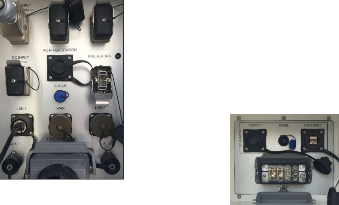
Fig. 19 – Interface panel on the rear side of the IBIS-ArcSAR Supply Unit
The I/O interfaces panel shown on front of Fig. 18Figure 1 includes (from
upper left to lower right in Fig. 19):
MAINS INPUT (100-240 Vac 50-60 Hz – 7 A) AC Mains connection;
AC OUTPUT (230 Vac 50 Hz 10 A): 230 Vac outlet for supplying
auxiliary equipment (only when the onboard generator is on);
WIND: socket for Wind Turbine;
DC INPUT: connection for external battery pack;
WEATHER STATION: socket for IBIS Weather Station;
PREHEATING: socket for preheating system (low temperature kit)
SOLAR (12 Vdc – 2 A): a plug for a solar panel which could be used to
charge the Genset battery;
LAN 1: Ethernet port connected to router LAN port;
WAN: Ethernet port connected to router WAN port;
LAN 2: Ethernet port connected to router LAN port;
AUX1 (12, 24, 48 Vdc – 4 A) outlet;
TRAILER SUPPLY (12 Vdc – 10 A) cable socket;
AUX2 (12, 24, 48 Vdc – 2 A) outlet;
Fig. 20 – Interface panel on the front side of the ArcSAR Supply Unit
The I/O interfaces panel placed on the front side includes (from left to right
in Fig. 20):
SOCKET POSITIONER: this socket allows the power supply and control
of the acquisition unit (sensor, positioner, cameras and GPS)
EV CAMERA section: not applicable to the ArcSAR system
4 IBIS-ArcSAR HARDWARE BREAKDOWN
IDS GeoRadar S.r.l. Confidential Information - Do Not Distribute MNG/2017/0016 Rev 1.0 19/ 78
The IBIS-ArcSAR is provided of four batteries which supply the system.
These batteries are set in an internal compartment placed on the right side
of the ArcSAR Supply Unit (Fig. 21).
Fig. 21 – Batteries compartment on the right side of IBIS-ArcSAR Supply Unit
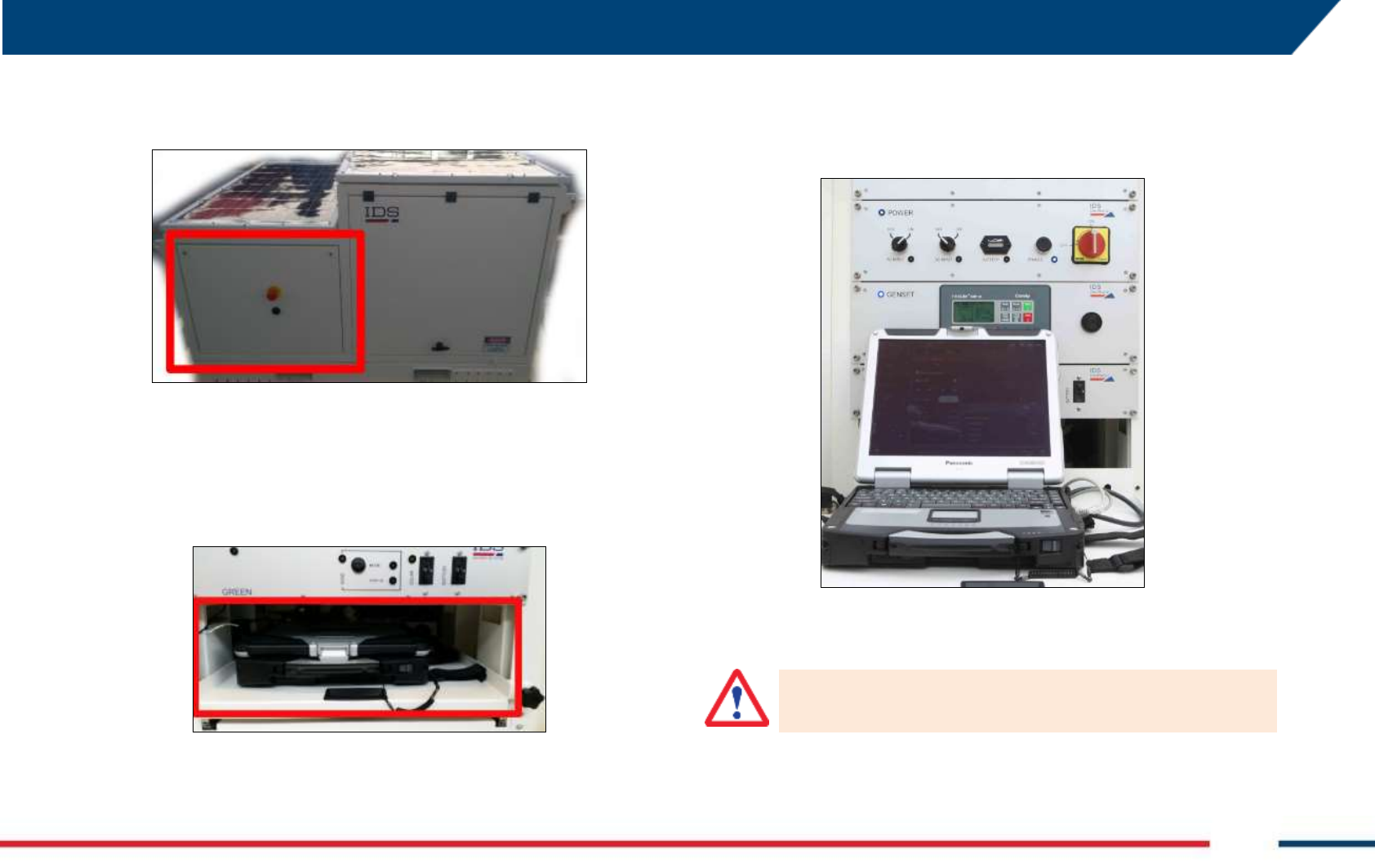
4.3.3 Laptop PC
The Laptop PC workspace is placed under the drawers of the Power Supply
Unit, in the left side of IBIS-ArcSAR (Fig. 22). The workspace is the lower
sliding drawer, as shown in Fig. 23.
Fig. 22 – Laptop drawer
The provided Laptop PC is a Panasonic Toughbook CF31 and it is supplied
with the IBIS Controller control and data acquisition software pre-installed.
The Laptop is used to control the Radar Sensor, the Positioner and the
other ArcSAR devices, manage the supplying of the System and allows the
communication between the field and the IBIS Guardian processing
software.
Fig. 23 – Panasonic Toughbook CF31
No communication software such as Firewall, Wi-Fi or antivirus must be
installed to avoid any conflict with the IBIS Controller software
Confidential Information - Do Not Distribute
IDS GeoRadar takes no responsibility for bad functioning if there is a
functional conflict between its software and any software installed on
the Laptop PC by the user. IDS GeoRadar does not guarantee that the
performance of its equipment will be maintained using a different
configuration from the recommended one
4.3.4 Generator
The integrated diesel generator (also known as Genset) is used as a back-up
source of energy. It is automatically managed with the software, so that
when batteries are low (and no energy is coming from the solar panels) it is
turned on to provide power.
Fig. 24 – Generator on the ArcSAR left side
Fig. 25 – Generator on the ArcSAR right side
The control unit, placed on Genset Module of the PSU, can start or stop the
Genset and manage alarm and warning messages from the Genset sensors
(e.g. lack of oil, empty tank, etc.).
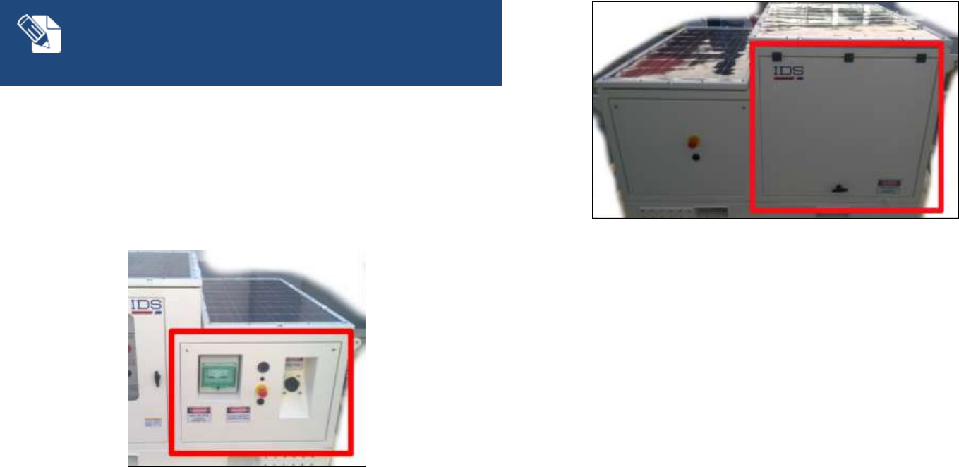
The Generator is installed and accessible from the right side of the IBIS-
ArcSAR. The Generator area can be divided in:
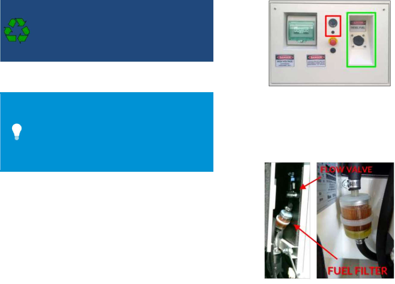
the left side includes the filling point for the fuel tank, the System
emergency stop red button with the related horn and the fuel level
indicator (Fig. 26); it also includes Circuit Breaker switchboard, with
the Generator general switch and a 220 Vac output switch (Fig. 99);
the right side is marked by a lifting door; the generator is located
behind the main door.
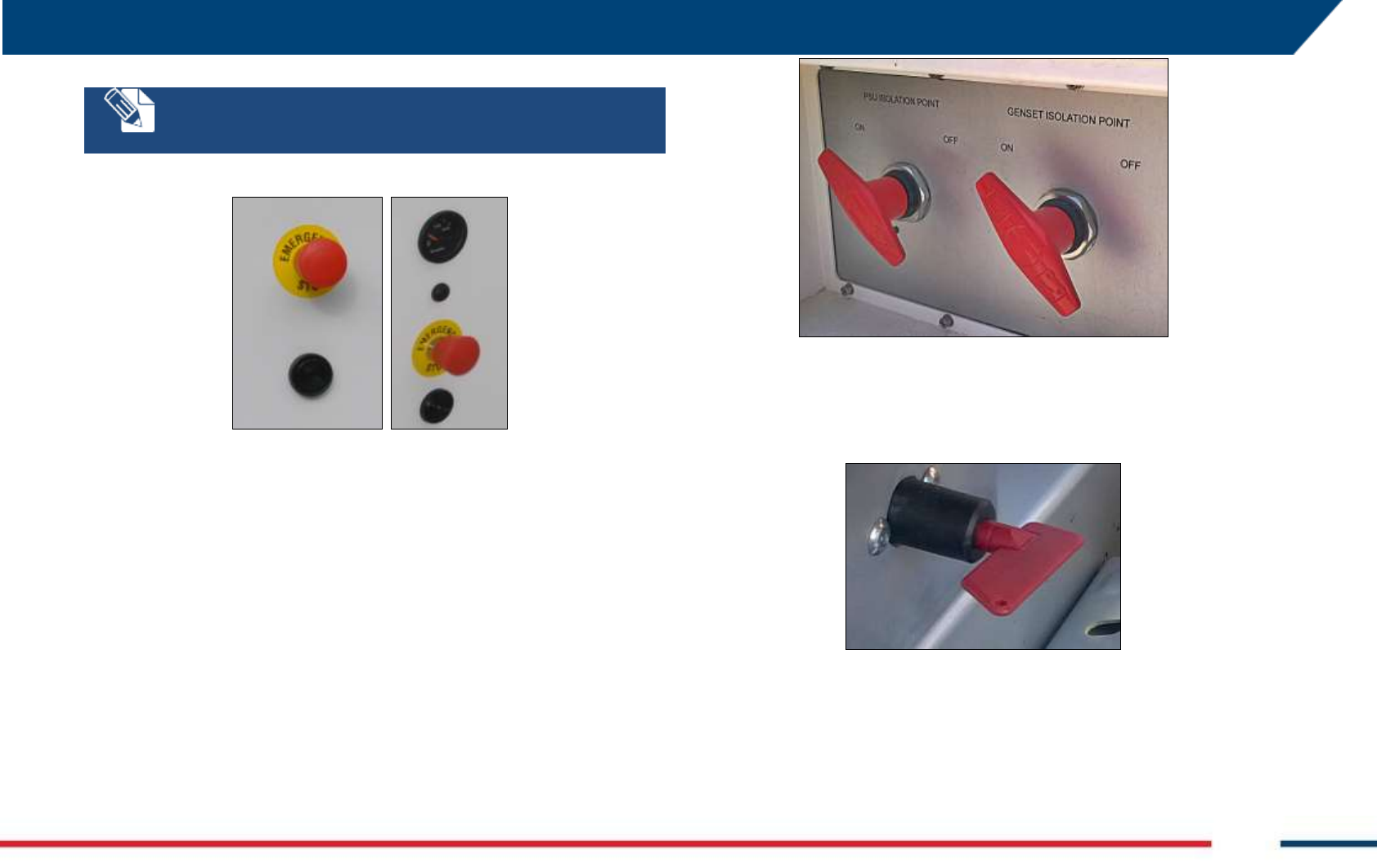
4.3.5 Electrical safety devices
IBIS-ArcSAR is provided of several electrical safety devices. In detail:
a red emergency stop button placed next to the generator fuel level
indicator;
a red emergency stop button placed on the battery panel side;
4 IBIS-ArcSAR HARDWARE BREAKDOWN
IDS GeoRadar S.r.l. Confidential Information - Do Not Distribute MNG/2017/0016 Rev 1.0 21/ 78
Every time the emergency stop button is released, the enable switch
has to be pressed to restore the system.
Fig. 26 – Red emergency stop buttons
two isolation points (red lever switches) placed on the front side of
the IBIS-ArcSAR: the left one allows the electrical isolation of PSU
batteries, the right one allows the electrical isolation of GENSET
battery (Fig. 27). The panel that contains these two switches can be
locked if necessary;
Fig. 27 – PSU and GENSET isolation points
an isolation point (a battery cut-off switch commanded with a key)
which allows the electrical isolation of the trailer lifting supports only
(Fig. 28).
Fig. 28 – Battery cut-off switch
4.4 Pole
The rear side of the ArcSAR is provided with a metallic pole. On the pole
can be installed optional components, as Weather Station or Wi-Fi Link or
the Genset solar panel. This pole can reach a height of about 3 meters from
Confidential Information - Do Not Distribute
its base (the total height depends on the trailer specs). The pole can be
tilted to facilitate the installation of every single component on it. Pole can
be rotated to point the Wi-Fi antenna towards the desired location.
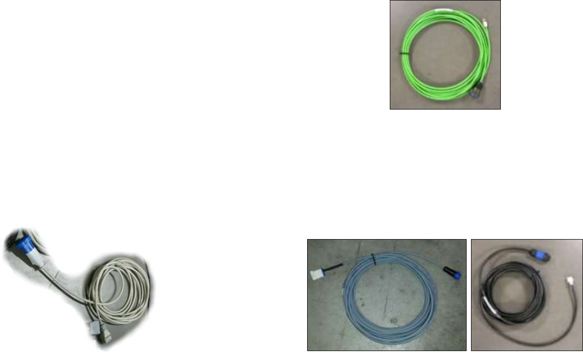
4.5 Additional items
Additional items are part of the IBIS-ArcSAR, shipped together with the
devices explained in the paragraphs below.
IBIS Radar Sensor Case
AC Mains cable (Fig. 148);
Supply Output cable to provide 220 Vac while generator is running
(Fig. 29);
Fig. 29 – 220 Vac output cable
2 Ethernet cable (Fig. 30);
Fig. 30 – Ethernet cable
1 48 V Power-over-Ethernet Wi-Fi Link cable (Fig. 39);
1 24 V Power-over-Ethernet cable (Fig. 39);
1 Aux 12 V cable (Fig. 31);
1 Aux 24 V cable (Fig. 31);
Fig. 31 – Aux 12 V - 24 V cables
External cable for Generator battery;
An additional cable is provided to supply the system with Mains AC power.
The power cable has a plug whose shape is suitable for the destination
country electric system.
4 IBIS-ArcSAR HARDWARE BREAKDOWN
IDS GeoRadar S.r.l. Confidential Information - Do Not Distribute MNG/2017/0016 Rev 1.0 23/ 78
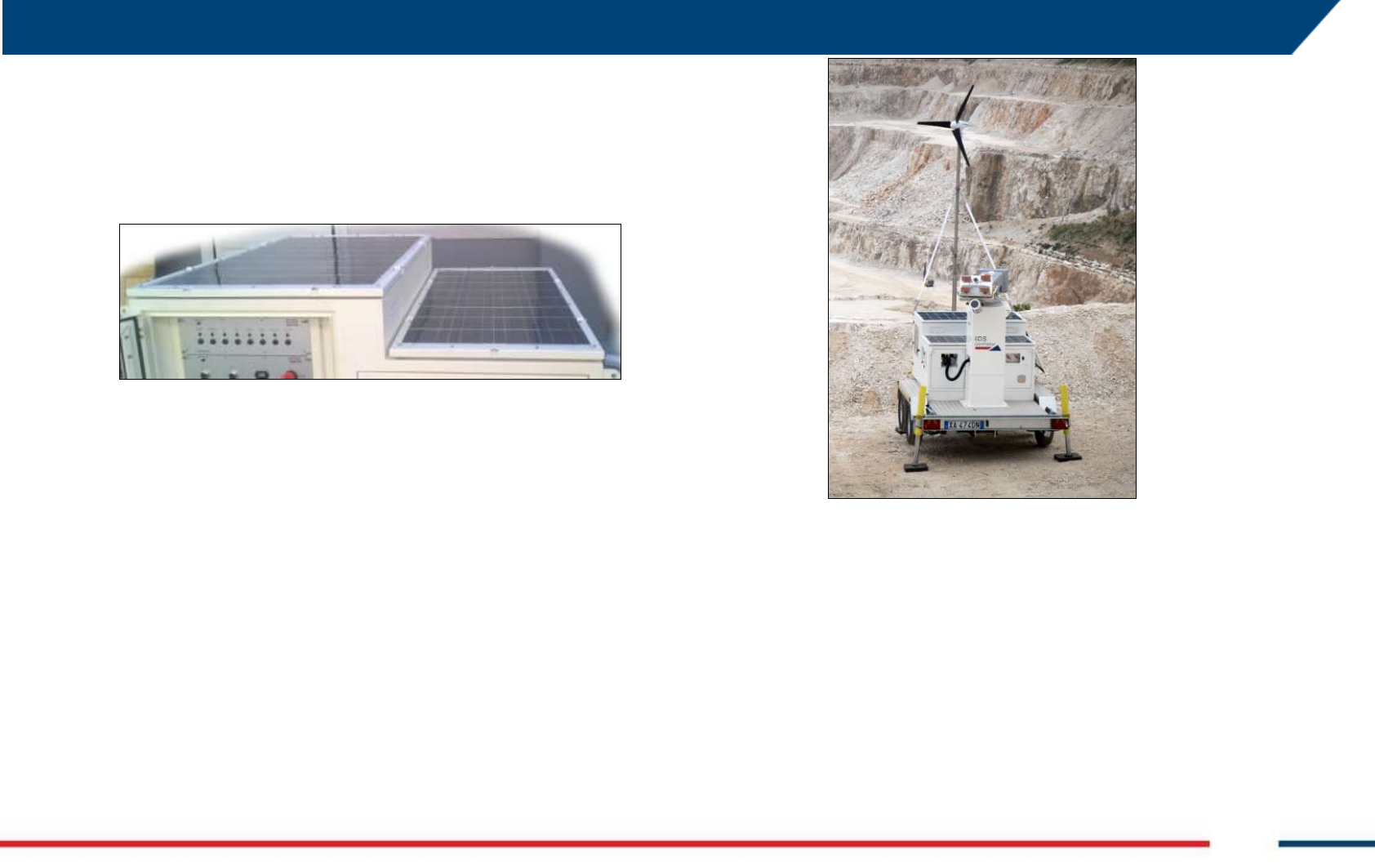
4.6 Solar Panels
The Solar Panels permit to exploit the solar irradiation and the reduction of
the need of the generator, therefore reducing its maintenance and fuel
consumption. The panels are placed on the top covers of IBIS-ArcSAR and
mounted on their frame.
Fig. 32 – Solar Panels
The solar panels are managed by Green Module placed on the PSU.
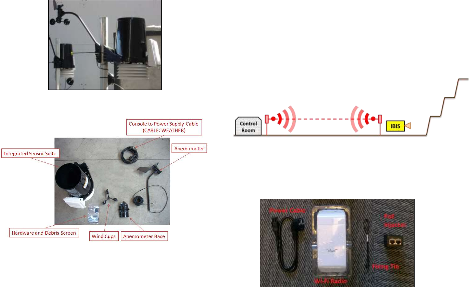
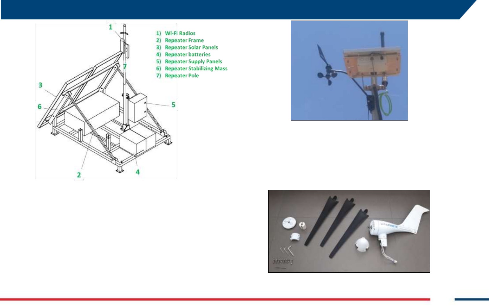
4.7 Wind Turbine (optional)
The Wind Turbine generates power from wind and helps to reduce of the
need of the generator, therefore reducing its maintenance and fuel
consumption. The Wind Turbine is installed on a pole mounted on the
Trailer shaft
Fig. 33 – Wind Turbine
The Wind Turbine is managed by Green Module placed on the PSU.
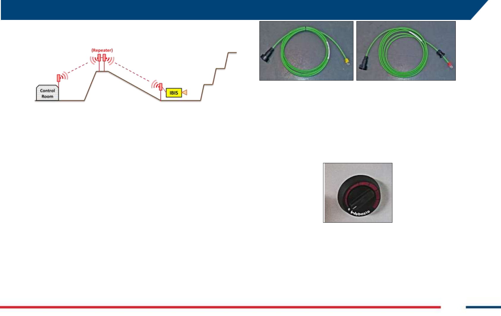
4.8 Weather Station (optional)
Weather Station provides info about meteorological data. The weather
sensors are temperature, pressure, humidity, wind speed and direction,
rain precipitation, Data Logger with internal temperature, pressure and
humidity (integrated in the ArcSAR PSU).
Confidential Information - Do Not Distribute
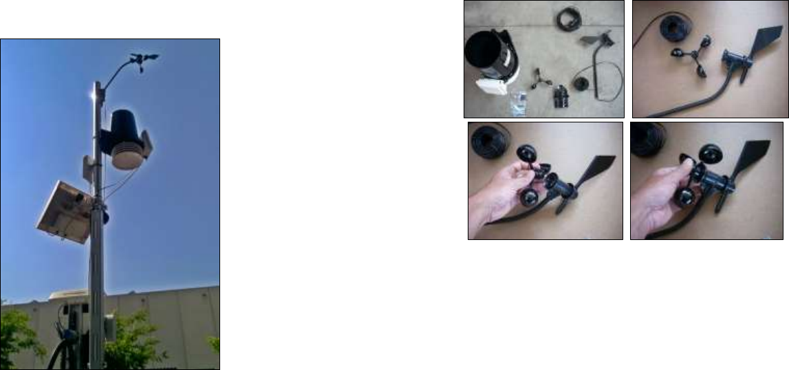
Fig. 34 – View of the Weather Station
Fig. 35– Components of the Weather Station
Please refer to the provided Weather Station manual for further details.
4.9 Wi-Fi Link (optional)
The Wi-Fi link allows the data transmission between the IBIS-ArcSAR
installation site, where IBIS Controller is installed on CF31, and the Control
Room, where IBIS Guardian workstation is present.
The basic layout of Wi-Fi Link is when the mine facilities have free line of
sight to the IBIS-ArcSAR or when their distance is less than 2 km (Fig. 36).
Fig. 36 – Wi-Fi Link with no Repeater
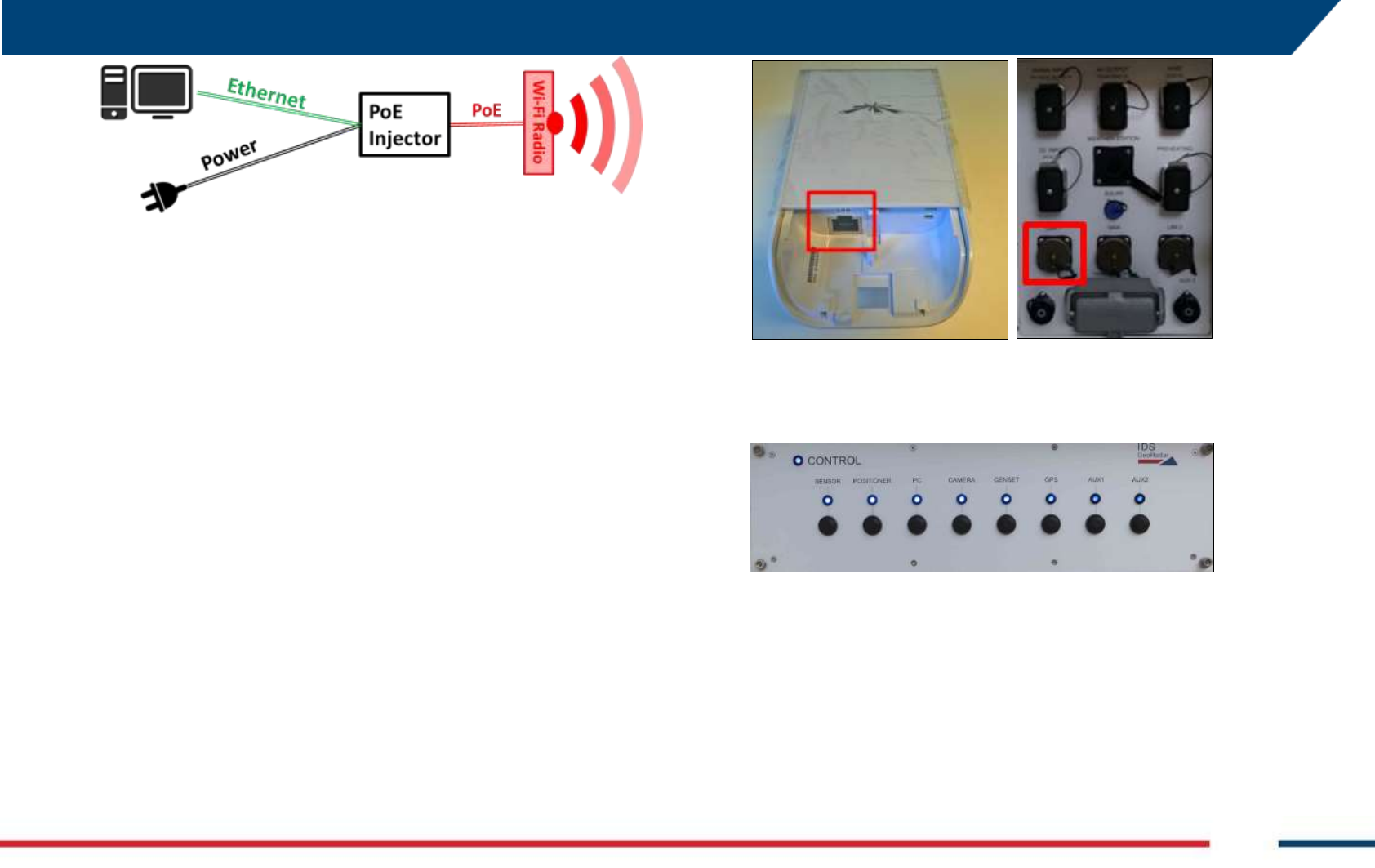
In this case the Wi-Fi Link is composed of a couple of Wi-Fi radios, supplied
by Power-over-Ethernet. One radio is located on the IBIS-ArcSAR, the other
radio is installed at the Control Room, and it’s connected to the IBIS
Guardian workstation.
Fig. 37 – Content of a Wi-Fi radio box
4 IBIS-ArcSAR HARDWARE BREAKDOWN
IDS GeoRadar S.r.l. Confidential Information - Do Not Distribute MNG/2017/0016 Rev 1.0 25/ 78
When the mine facilities have no free line of sight to the IBIS-ArcSAR or
when their distance is more than 2 km (Fig. 38), a Repeater is needed.
Fig. 38 – Wi-Fi Link with repeater
The Repeater is composed of an additional couple of radios and it has a
specific power supply with solar panels and batteries. The two Repeater
Wi-Fi Radios are connected together with an Ethernet cable.
The Repeater is supplied with 2 back up batteries giving an autonomy of
about 5 days. The Repeater power supply can be supplied by a couple of
photovoltaic panels or by the Mains Supply. An alternative option is to
detach the batteries and charge them using the battery charger (e.g. if not
enough solar power is provided for several days).
Together with the IBIS-ArcSAR Wi-Fi, two Power-over-Ethernet (PoE) cables
are provided:
a 24 Vdc PoE cable to supply IBIS Wi-Fi (Fig. 39 left – yellow plug).
a 48 Vdc PoE cable (Fig. 40 right – red plug) to different supply needs;
Fig. 39 – Wi-Fi PoE cables
4.10 Low temperature kit (optional)
The Heater allows the IBIS-ArcSAR working in cold environment. Webasto®
Heater can be controlled by a thermostat control knob which is installed in
the Laptop PC drawer (Fig. 40).
Fig. 40 – Webasto® Heater temperature control
It is recommended to turn the control knob within the first two marks.
Once the Heater internal engine is started, it is able to warm up all the
internal compartment of the IBIS-ArcSAR.
Confidential Information - Do Not Distribute
5 FIRST ArcSAR SETUP
Don’t use electric screwdriver while working with IBIS ArcSAR hardware parts.
5.1 Unpacking the wooden boxes
1. Open the wooden shipped boxes which contains ArcSAR Trailer,
ArcSAR Positioner and ArcSAR Supply Unit;
2. Take the box placed under the Trailer: it contains some items to
install the Positioner and the Supply Unit on the Trailer. This box
contains:
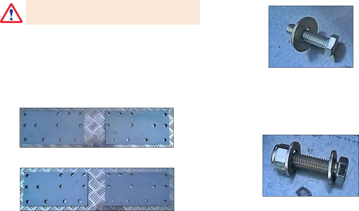
4 fixing pierced plates for the Supply Unit installation;
(right side)
(left side)
Fig. 41 – Fixing pierced plates
16 screws (M10 x 35 mm hexagonal Head) to fix plate to the
Trailer;
Fig. 42 - M10 x 35 mm hexagonal head screw with M10 washer
32 screws (M10 x 35 mm hexagonal head) to fix plate to the
Supply Unit;
48 M10 washers;
4 screws (M12 x 50 mm hexagonal head) provided with 2
washers and self-blocking nuts;
Fig. 43 - M12 x 50 mm hexagonal head screw with self-blocking nut and washer
3. Descend the Trailer from the box and brake it using the hand-brake
and the chops.
5.2 Supply Unit on the trailer deck
5 FIRST ArcSAR SETUP
IDS GeoRadar S.r.l. Confidential Information - Do Not Distribute MNG/2017/0016 Rev 1.0 27/ 78
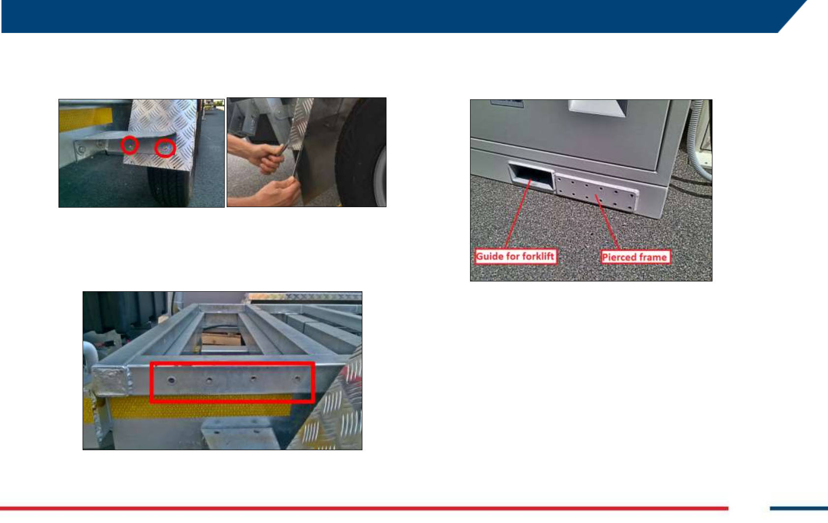
1. Remove the mudguards from the Trailer (use two 13 mm wrenches).
Every mudguard has 4 fixing screws (two screws for each side);
Fig. 44 – Mudguards fixing screws
2. after the mudguards removal, the 16 Trailer holes (4 holes for each
side) become well visible;
Fig. 45 – Holes on the Trailer
3. install the Supply Unit on the Trailer for first. In this way the right
balance of the trailer is ensured. If you look close to the forks guides,
you can see a pierced frame close to every guide: every frame has a
grid of holes to install the trailer fixing plates;
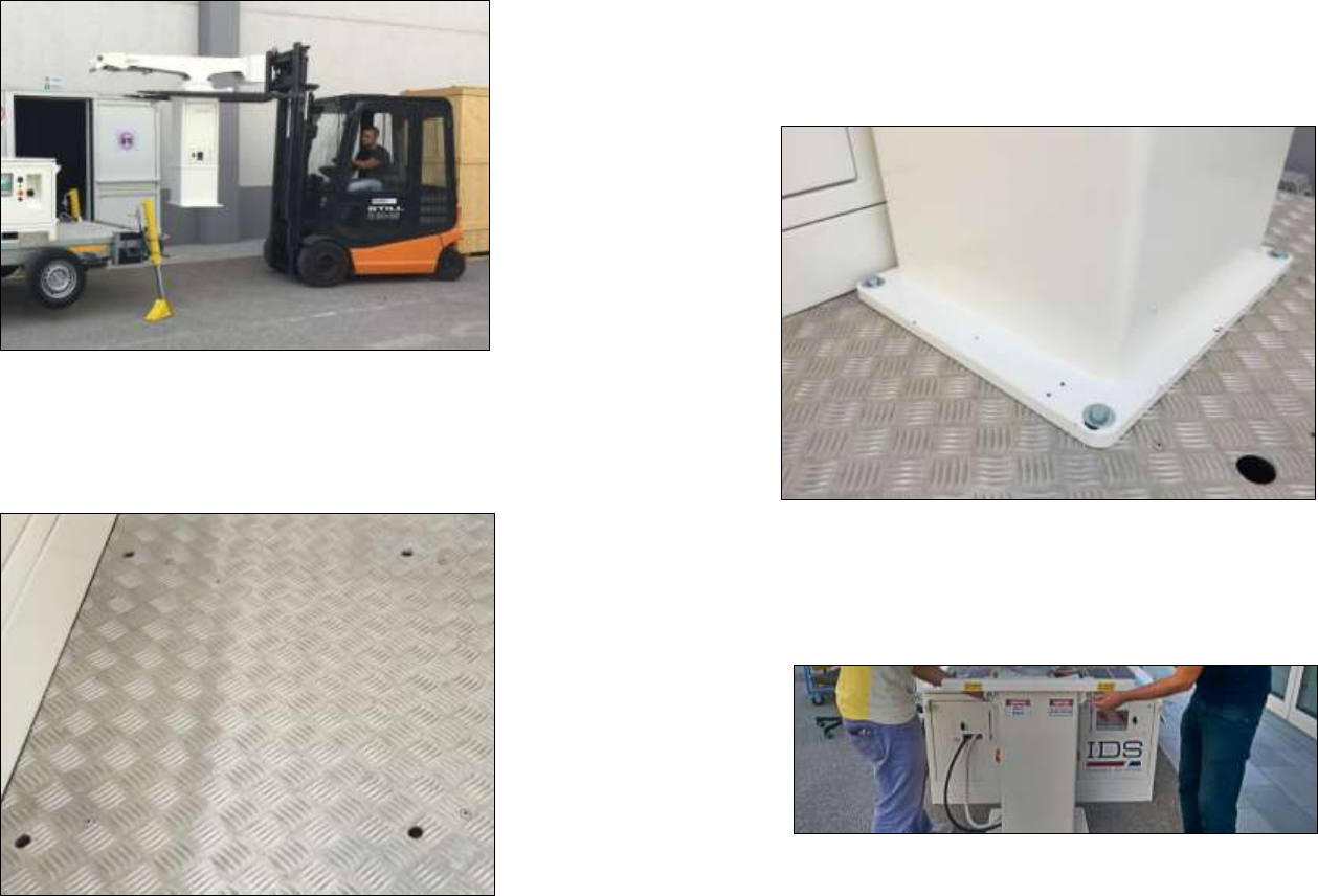
Fig. 46 – Detail of Supply Unit bottom
4. lift the Supply Unit with the forklift, inserting the forks into the
specific guides placed at the bottom side. It is recommended to lift
the Supply Unit from the heaviest side of the Supply Unit (generator
and battery side)
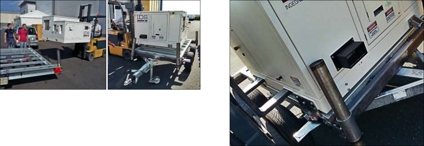
Confidential Information - Do Not Distribute
Fig. 47 – Lifting the Supply Unit with the forklift
5. align the corners of the Supply Unit to the limits of the Trailer. In
detail, on the shaft side, align the edge of the Supply Unit with the
edge of the last upper bar of the trailer. The position of the holes of
the Trailer and the Supply Unit can help to calculate the right
alignment;
Fig. 48 – Supply Unit aligned with the Trailer
6. take the fixing plates: every plate has its right position. The carved
arrow indicates how the plates have to be placed: the arrow has to
face the trailer shaft (Fig. 49). helps to understand the position of the
plates on the Trailer;
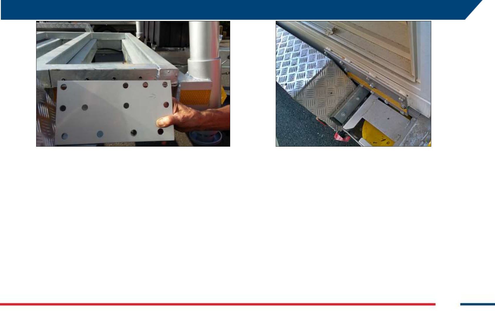
5 FIRST ArcSAR SETUP
IDS GeoRadar S.r.l. Confidential Information - Do Not Distribute MNG/2017/0016 Rev 1.0 29/ 78
Fig. 49 – Fixing plates with the arrow facing the trailer shaft
7. fasten the screws (M10 x 35 mm hexagonal Head) in order to fix the
plates to the Trailer (4 lower holes): a 17 wrench is needed;
8. fasten the screws (M10 x 35 mm hexagonal Head) in order to fix the
plates to the Supply Unit (8 upper holes): a 17 mm wrench is needed;
9. check the fastening of the screws in order to ensure the perfect
immobility of the Supply Unit;
10. install again the mudguards of the Trailer (Fig. 50).
Fig. 50 – Fixing plates properly installed
5.3 Acquisition Unit on the trailer deck
1. Lift the Acquisition Unit with the forklift, using the provided metal
wings (you have to remove them after the installation). Lift the
Acquisition Unit with the back side facing the forklift. Use the forks
edges to lift the Acquisition Unit, in order to have enough space to
place the Acquisition Unit on its position on the Trailer;
Confidential Information - Do Not Distribute
Fig. 51 – Lifting the Acquisition Unit with the forklift
2. Look at the base of the Acquisition Unit: there are four holes at the
corners: Align these holes with the four holes drilled on the slip
aluminium sheet of the Trailer;
Fig. 52 – Drilled holes on the Trailer for Acquisition Unit installation
3. fasten the screws (M12 x 50 mm hexagonal head) through the holes
in order to fix the Acquisition Unit base to the trailer (two 19 mm
wrenches are needed). Check the fastening of the self-blocking nut in
order to ensure the perfect immobility of the Acquisition Unit;
Fig. 53 – Fix the Acquisition Unit base to the trailer
4. remove the wings frame from the Acquisition Unit (Fig. 54). A 14 mm
Allen Key and a 27 mm wrench are required to unfasten the four
screws with related nuts (Fig. 55)
Fig. 54 – Removing wings from installed Acquisition Unit
5 FIRST ArcSAR SETUP
IDS GeoRadar S.r.l. Confidential Information - Do Not Distribute MNG/2017/0016 Rev 1.0 31/ 78
Fig. 55 - Wings removed from the Acquisition Unit
5.4 Pole on the Supply Unit
A metallic pole is provided inside its own wooden box or into the Trailer
wooden box. The pole has to be installed on the rear side of the IBIS-
ArcSAR. Two guides provide its fastening. The lower guide allows the fixing
of the pole base and the possibility to lower it to facilitate the installation of
the devices (Fig. 56). The pole is provided with a sliding leg that allows to
maintain the pole in horizontal position while the user is installing these
devices.
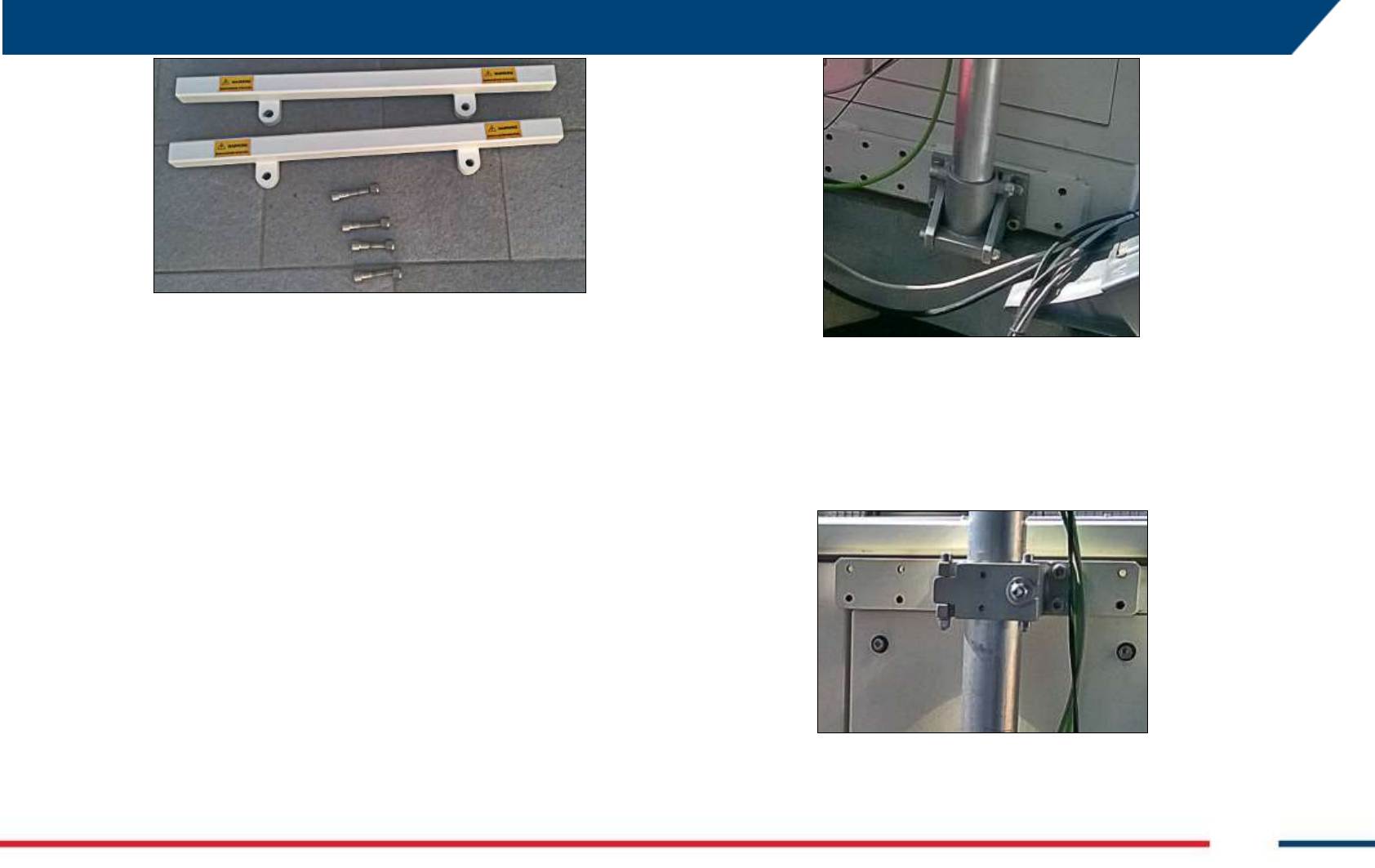
Fig. 56 – Base of the pole installed on its guide
The upper guide ensures a complete fixing of the pole (Fig. 57). To open or
close the guide, it is necessary to unscrew the security bolt and move the
security plate (two wrenches are needed).
Fig. 57 – Upper pole guide for the ArcSAR
Confidential Information - Do Not Distribute
The installation of the Weather Station, Wi-Fi Link and Generator Solar
Panel (see Paragraph 5.5) has to be done with their cables already
connected (Fig. 58). The pole can be rotated to set the best line of sight of
the Wi-Fi;
In order to increase the stability of the pole, the tie-rod metallic wire has to
be hook with the karabiners to the ArcSAR Supply Unit. If the tie-rod
metallic wire is not well drawn, it is necessary to fasten the tie-rod.
Fig. 58 – Pole with installed devices
5.5 IBIS Accessories on Pole
5.5.1 Weather Station
The following sequence of operations should be performed in order to
install the Weather Station. The provided pole can be used as a support.
The Weather Station is placed in the big cardboard shipped box.
Fig. 59 – Installation steps (1/3)
1. take the anemometer arm and wind cups;
2. push the wind cups into the stainless steel shaft of the anemometer
arm;
3. slide the wind cups up the shaft as far as possible;
5 FIRST ArcSAR SETUP
IDS GeoRadar S.r.l. Confidential Information - Do Not Distribute MNG/2017/0016 Rev 1.0 33/ 78
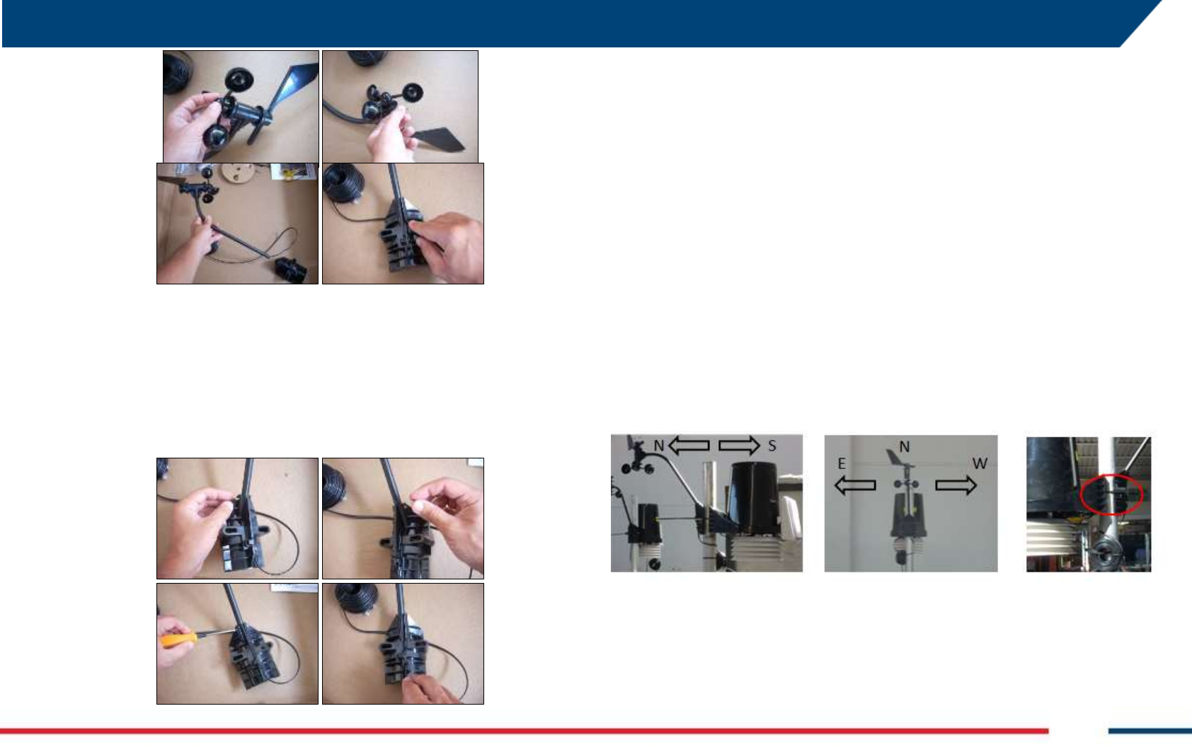
Fig. 60 – Installation steps (2/3)
4. make sure the wind cups are not loose;
5. tighten the set of screw with the Allen wrench provided. Try to spin
the wind cups. They should spin freely;
6. insert the anemometer arm into the base, sliding the cable through
the notch in the base as shown in the figure;
Fig. 61 – Installation steps (3/3)
7. make sure to align the small hole in the arm with the holes in the
base;
8. insert the machine screw through the holes in the base and arm;
9. slide the tooth-lock washer and hex nut onto the machine screw.
Tighten the hex nut while holding the screw with a Phillips head
screwdriver to prevent it from turning;
10. press the sensor cable firmly and completely into the zig-zagging
channel in the base, starting from the arm and progressing
downward to the bottom of the base. Make sure to press the cable
into the channel at the bottom of the grove;
11. fix the Weather Station on the provided pole or something similar.
This can be performed using the anchoring elements provided, or
simply by using cable ties.
The anemometer arm should be pointing North in order to obtain the right
values in terms of wind direction.
Fig. 62 – The Weather Station can be easily fixed to a pole using cable ties
Using cable ties represent a valuable solution easily adaptable to different
poles or situations but in some cases, the anchoring elements provided can
be used instead. Hence, you will need to remove first the rain gauge funnel
as it is shown in the Fig. 63.
Confidential Information - Do Not Distribute
Fig. 63 – Remove the rain gauge funnel
The anchoring elements (Fig. 64) allow different configuration: for further
explanations please refer to the specific manual of this device.
Fig. 64 – Weather Station anchoring elements
The last part of the installation consists in making all the necessary
connections between the Weather Station and the Power Supply.
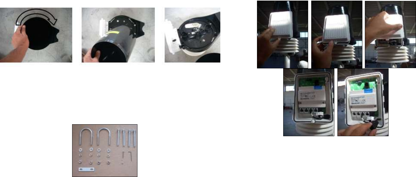
Fig. 65 – Weather Station cable connections (1/6)
1. locate the white box in front of the weather station and its white tab
at the bottom center of the box cover;
2. lift the tab away from the box while sliding the cover up: the sensor
connectors are now visible once the cover is removed;
3. get the protective foam out of the cable access port between the
cables and set the foam insert aside;
5 FIRST ArcSAR SETUP
IDS GeoRadar S.r.l. Confidential Information - Do Not Distribute MNG/2017/0016 Rev 1.0 35/ 78
Fig. 66 – Weather Station cable connections (2/6)
4. insert the anemometer cable end into the cable access port with the
connector lever down;
5. firmly insert the end of the anemometer cable into the connector
labelled WIND. The lever clicks into place;
6. make sure the cables lies flat on the bottom of the cable access port;
7. take the cable (CABLE: WEATHER) to connect the weather station
console to the power supply;
Fig. 67 – Weather Station cable connections (3/6)
8. insert the WEATHER cable end into the cable access port with the
connector lever down;
9. firmly insert the end of the cable into the connector labelled
CONSOLE. The lever clicks into place;
10. firmly insert the foam between the cables and at the top of the
cables access port, making sure the foam entirely seals the access
port, leaving no holes;
11. connect the other end of the WEATHER cable to its socket in the I/O
interfaces panel placed on the rear side of the IBIS-ArcSAR (red box in
Fig. 68);
12. make sure the external ring is well tightened.
Confidential Information - Do Not Distribute
Fig. 68 – Weather Station connection on the I/O interface right panel
The Weather Station is supplied when the System Switch on the front
Power Module is turned on and when the internal PSC is powered. Weather
station power supply can be managed from IBIS Controller software. As
reported above, the pole can be tilted to ease the access to the installed
Weather Station.
5.5.2 Wi-Fi
The Wi-Fi Link can be deployed with two different layout, depending on the
case, as already explained in Par. 4.9.
Basic Layout when there is free line of sight between Control Room
and IBIS-ArcSAR, (no physical obstacles along the line of sight);
Basic Layout + Repeater when there is absence of line of sight
between the Control Room and the IBIS-ArcSAR.
The Wi-Fi Link components are placed in the big shipped cardboard box.
The radio antennas arrive on-site already set with the proper configuration.
In detail, the radio installed at the Control Room (Guardian side) is set as
Access Point. The radio installed at the IBIS-ArcSAR (Controller side) is set as
Station. The Repeater couple of radio are set as in the same way. As other
IBIS devices, Wi-Fi is set with default IP address: check the IPs address
before installing the antennas.
Wi-Fi radio antennas can be managed using their software AirOS ®
installed on the IBIS-ArcSAR CF31 computer.
To access it the user has to open your web browser and connect to
https://10.0.0.106 (Access Point) or http://10.0.0107 (Station).
The Wireless page allows antenna type modify (Wireless Mode), while
the Network page allows to change the IP of the device.
PoE Ethernet connectors are supplied with 24/48 Vdc. Connect
peripherals only with their specific cable.
5.5.2.1 Basic Wi-Fi layout
Control Room side
1. install a pole outside the Control Room, in a position with a cleared
view towards the IBIS-ArcSAR and that is at less than 100 m from the
workstation or server in the Control Room;
2. install the first radio (configured as Access Point AP) on the pole
using the provided tie: the radio has to face the IBIS-ArcSAR;
3. connect the Ethernet cable from the PoE injector to the Guardian
workstation and the provided PoE cable from the PoE injector to the
Wi-Fi Radio, opening the bottom part of the antenna (Fig. 70);
4. supply the Wi-Fi Radio, connecting the power cable to the PoE
injector;
5 FIRST ArcSAR SETUP
IDS GeoRadar S.r.l. Confidential Information - Do Not Distribute MNG/2017/0016 Rev 1.0 37/ 78
Fig. 69 – Control Room installation
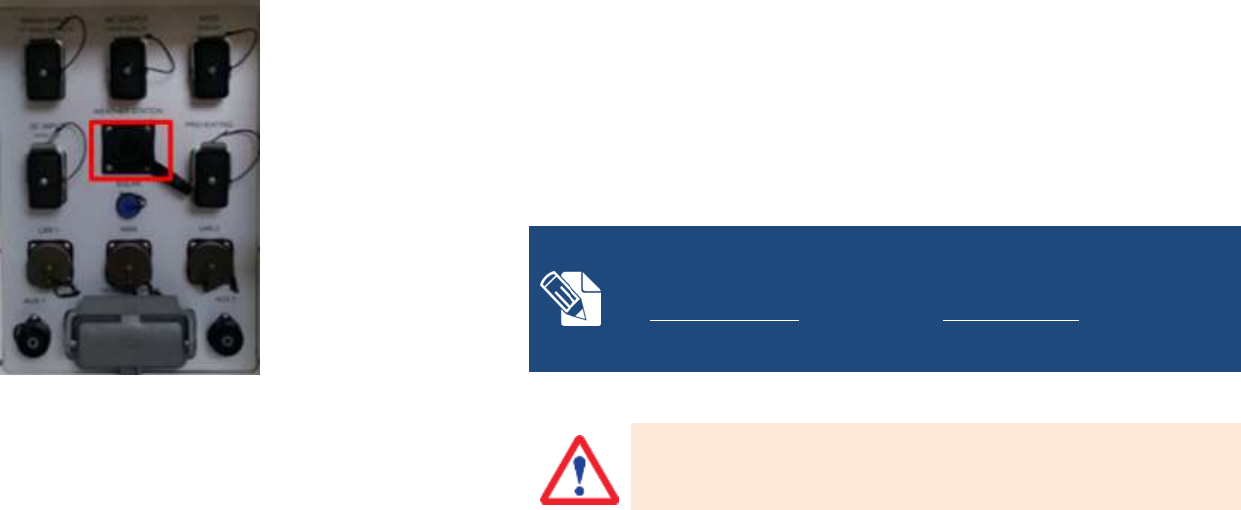
IBIS-ArcSAR side
1. install the Wi-Fi radio (configured as Station) on the ArcSAR pole so
that it faces the Wi-Fi radio installed at the Control Room. Fasten the
radio with provided tie;
2. open the bottom part of the Wi-Fi radio and connect the provided
PoE 24 Vdc cable with the yellow plug (Fig. 70) to the socket. Connect
the other side of the cable to the specific Wi-Fi on the rear I/O
interface panel (red box in Fig. 70).
Fig. 70 – Wi-Fi sockets in the radio and in the rear I/O interface panel
3. in the Control Module of the PSU, turn on the WIFI switch to supply
the Subscriber Unit (Fig. 71);
Fig. 71 – Wi-Fi switch on the front side of Control Module
5.5.2.2 Basic Wi-Fi + Repeater Layout
If the repeater is needed, an additional couple of radios has to be installed.
Before the installation, it is required to make a survey in order to find the
appropriate position to set the Repeater Unit. It must have a cleared view
towards the IBIS-ArcSAR and the Control Room. The installation of the
Repeater can proceed as follows:
Confidential Information - Do Not Distribute
1. install the Repeater frame with its pole on the selected installation
point of the Repeater and install the couple of Radios on it. The Radio
set as Access Point AP has to face the IBIS-ArcSAR, while the antenna
set as Station has to face the Control Room. Fasten radios with
provided ties;
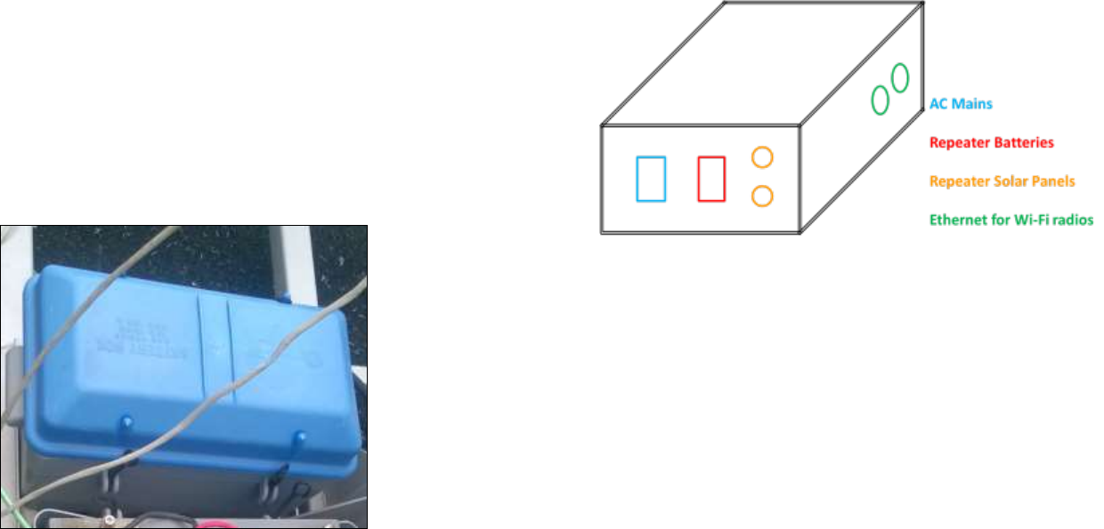
2. install the Repeater batteries, connecting them to the Repeater
Supply Panel (Fig. 72) using the provided cable with specific pins; put
the blue covers on them;
Fig. 72 – Repeater battery with blue cover installed
3. install the Repeater Solar Panels on their frame and then, plug their
cables to the Repeater Supply Panel;
4. if the AC Mains is available at the Repeater site, supply the batteries
plugging the specific cable to the Repeater Supply Panel;
Fig. 73 – Schematic diagram of the Repeater Supply Panel
5. connect the radios to the Repeater supply panel with the Ethernet
cables: in this way the radios will be supplied by the Repeater
batteries and they will be connected together with an internal
Ethernet cross cable;
6. install the Repeater Supply Panel on the pole;
7. fill up the stabilizing mass with water.
5 FIRST ArcSAR SETUP
IDS GeoRadar S.r.l. Confidential Information - Do Not Distribute MNG/2017/0016 Rev 1.0 39/ 78
Fig. 74 - Schematic diagram of the Repeater Unit
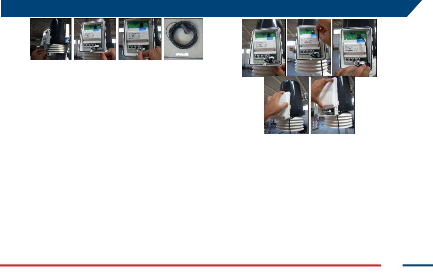
5.5.3 Generator Solar Panel
Take the generator solar panel and install it on the metallic pole, using a
wrench to fasten it to the pole (Fig. 75). Connect the related cable to its
socket one the left I/O interface panel. The panel is able to charge the
internal battery of the generator, thus remember to set the right inclination
to optimize the panel efficiency.
Fig. 75 – Genset solar panel installed on the pole
5.6 Wind Turbine and Pole Installation and Setup
1. Open the box containing the Wind Turbine installation kit: the
included items are the ones shown in Fig. 76;
Fig. 76 – Wind Turbine installation Kit
Confidential Information - Do Not Distribute
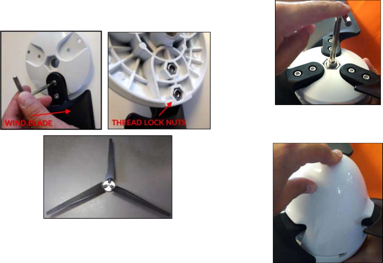
2. Join together the three blades to the front part of the wind turbine
(Fig. 77): fasten each blade to the white circle by using the thread lock
nuts.
Fig. 77 - Fixed blades
3. mount the blades block on the main wind turbine body: tight the nut
as in Fig. 78.
Fig. 78 – Tight the nut to fix the blades block to the Wind Turbine body
4. apply the protective cap to the front side of the blades block,
pressing it firmly until it snaps (Fig. 79);
Fig. 79 – Protective Cap installation
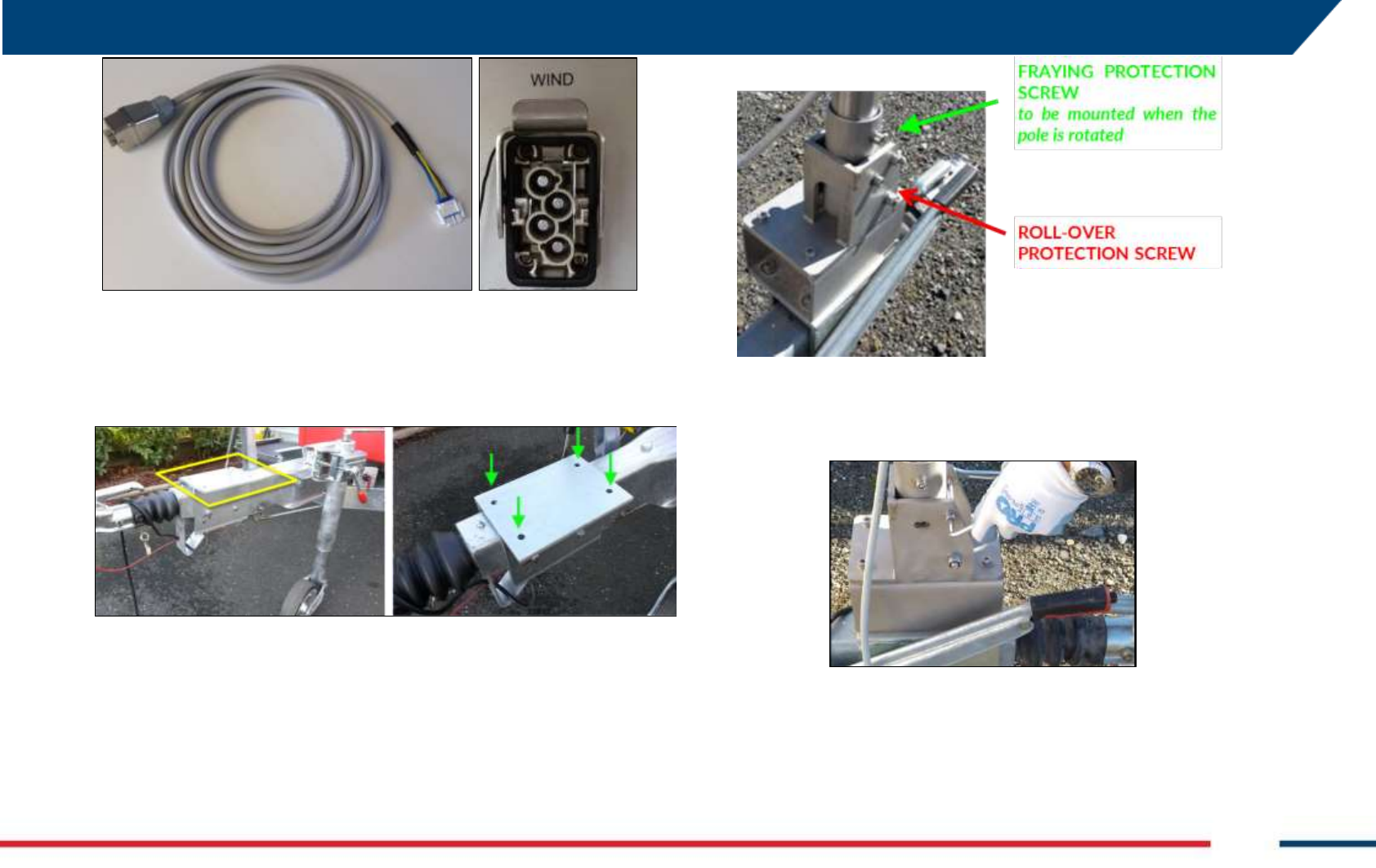
5. Connect the Wind cable to its socket in the I/O connector box (Fig. 80).
5 FIRST ArcSAR SETUP
IDS GeoRadar S.r.l. Confidential Information - Do Not Distribute MNG/2017/0016 Rev 1.0 41/ 78
Fig. 80 - WIND cable and its socket in the I/O Connector box
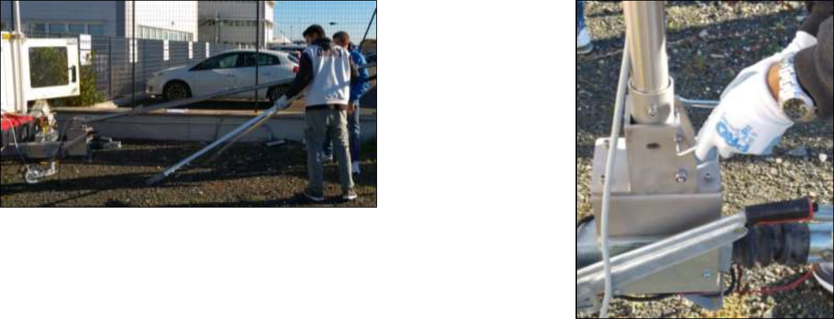
6. Mount the pole metallic base (Fig. 82) on the plate present on the
front part of the trailer shaft (Fig. 81). Four screws and nuts are
provided to fix the base;
Fig. 81 – Plate installed on the front part of the trailer shaft
7. Notice that pole metallic base is provided with a fraying protection
screw and a roll-over protection screw (Fig. 82);
Fig. 82 – Pole metallic base installed on the trailer shaft
8. Remove the roll-over protection screw with an Allen key and spanner
(Fig. 83). Once free, turn the base holder almost horizontally;
Fig. 83 - Remove the roll-over protection screw
9. The Wind Turbine pole is divided in two pieces which have to be
connected with a metallic joint: let the Wind cable pass inside the
three elements (Fig. 84 above), bringing it out from the Wind pole top
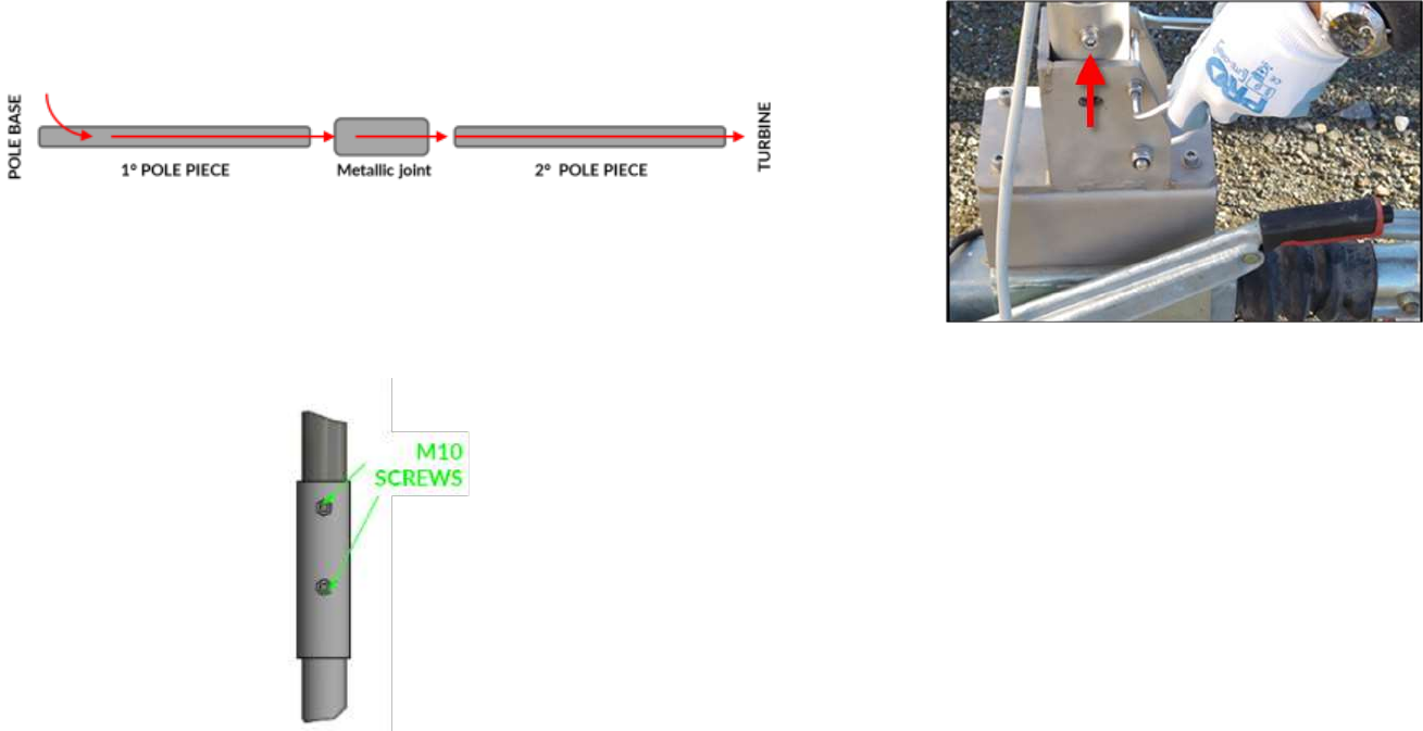
Confidential Information - Do Not Distribute
part, where the wind turbine body will be installed (see Fig. 87 as
reference).
Fig. 84 – Wind cable installed in the pole
10. Join the pole pieces with the metallic joint (Fig. 85), fasten M10 screws
to block the two metallic pipes;
Fig. 85 – Metallic pole joint
11. Insert the pole into the holder located at the base of the trailer and
extract the support leg of the pole to maintain the pole lifted in
horizontal position;
12. With an Allen key and spanner, secure the pole to its base holder
fastening the fraying protection screw;
Fig. 86 – Secure the pole to its base holder
13. Plug the white connector coming out from the Wind Turbine with the
Wind cable white connector coming out from the pole top (Fig. 87).
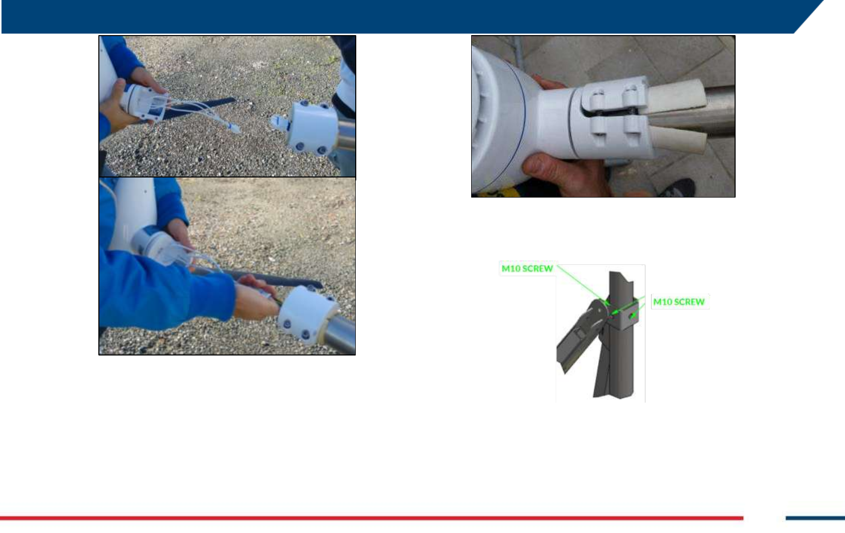
5 FIRST ArcSAR SETUP
IDS GeoRadar S.r.l. Confidential Information - Do Not Distribute MNG/2017/0016 Rev 1.0 43/ 78
Fig. 87 – Wind Turbine connectors setup
14. Fix and tighten the wind turbine to the pole fastening the related
screws (Fig. 88);
Fig. 88 – Wind Turbine tightened to the Pole
15. Install the two anchoring bars to the pole (Fig. 89 and Fig. 89) fastening
the M10 screws;
Fig. 89 – Anchoring bars installation on the Wind Pole
Confidential Information - Do Not Distribute
Fig. 90 – Anchoring bars installed on the Wind Pole
16. Lift the Pole in vertical position;
17. With Allen keys and spanners, tighten all the screws needed to
secure the pole to the trailer, take care to keep the screw head on
the side of the hand brake.
Fig. 91 – Pole tightened to the trailer
18. secure the pole to the Supply Unit Module, using the specific nuts
and washers;
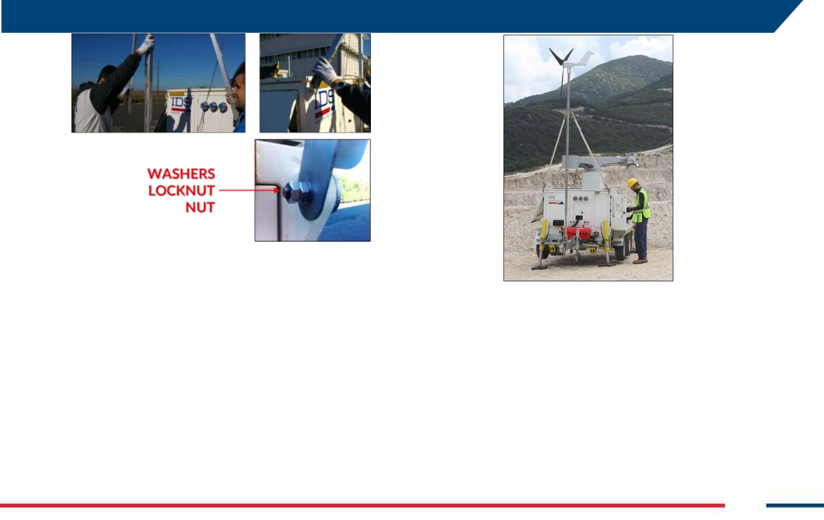
5 FIRST ArcSAR SETUP
IDS GeoRadar S.r.l. Confidential Information - Do Not Distribute MNG/2017/0016 Rev 1.0 45/ 78
Fig. 92 – Secure the Wind Pole to the ArcSAR Supply Unit
Fig. 93 – Wind turbine and pole installed on IBIS ArcSAR
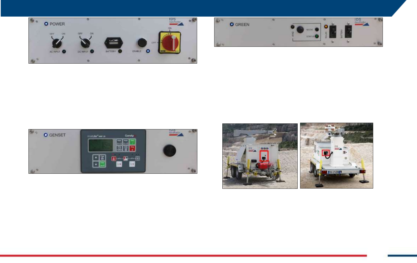
5.7 Trailer cable connection
1. open the rear I/O interface panel shown in Fig. 94 and check if the
Trailer Supply cable is correctly connected to its plug;
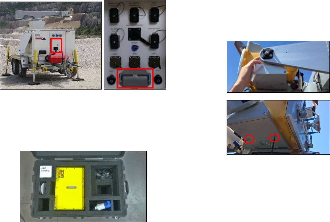
Confidential Information - Do Not Distribute
Fig. 94 – I/O Interfaces panel containing the Trailer Supply socket
5.8 IBIS Sensor Setup
For the first installation the Radar Sensor, with the 4 Antennas and the
Pointing Camera already installed on it, is shipped in a big cardboard. (Fig.
95).
Fig. 95 – Radar Sensor case
To set correctly the Radar Sensor, follow the steps below:
Fix the Radar Sensor on its support on the end of the positioner arm
by adjusting the center guide pivot of the sensor on its housing and
by screwing the 4 screws with the help of an allen key. (Fig. 96);
Fig. 96 – Installing the Radar Sensor into its housing
connect the Ethernet and Power Supply cable from to the Radar
Sensor. Screw together socket caps to prevent dust or water heap
(Fig. 97);
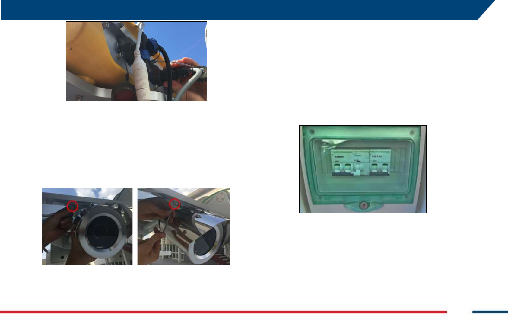
5 FIRST ArcSAR SETUP
IDS GeoRadar S.r.l. Confidential Information - Do Not Distribute MNG/2017/0016 Rev 1.0 47/ 78
Fig. 97 – ETHERNET and SUPPLY connections to the Sensor
connect the Ethernet (white cable) and Supply (blue cable) plugs to
the related wires of the Pointing Camera.
5.9 Panoramic Camera Setup
Mount the panoramic camera below the radar trolley using the 4 screws
and washers as shown in Fig. 98
Fig. 98 – Installing the Panoramic Camera
5.10 Supply Unit and Acquisition Unit Connections Setup
Connect the POSITIONER cable from the I/O Interface placed on the front
side of the ArcSAR Supply to the socket panel placed at the base of the
ArcSAR Acquisition Unit (Fig. 11);
5.11 Safety Electrical devices Setup
5.11.1 Genset RCD on
Open the Circuit Breaker Panel and turn the GENSET switch on (Fig. 99), in
order to allow generator operations;
Fig. 99 – GENSET RCD panel
5.11.2 PSM and Genset isolation point on
Open the Isolation Point switchboard, placed on the front side of the
ArcSAR Supply Unit, turning on the GENSET and PSU Isolation Point switch
(Fig. 100);
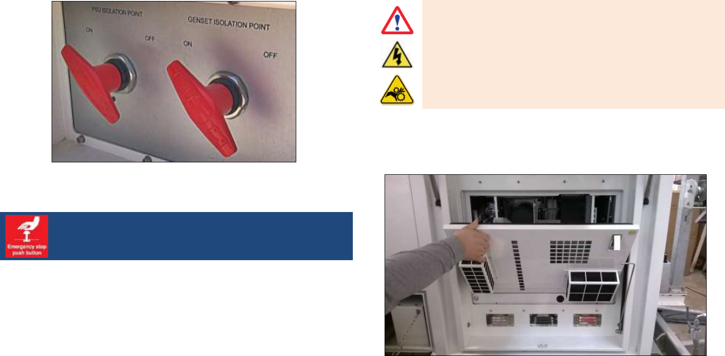
Confidential Information - Do Not Distribute
Fig. 100 – PSU and GENSET Isolation Points switch turned on
Remind to control the releasing of the emergency stop buttons. If the
emergency stop button is pushed, devices will be electrically isolated.
5.12 Generator First Setup
5.12.1 Oil refill
Before starting this operation, a dry cloth, engine oil and a funnel are
required. Then follow the steps below:
make sure the engine lays on a levelled surface;
stop the generator and isolate it, turning off the GENSET switch on
the PSU front door and the Genset Isolation Point switch;
WARNING
SHOCK HAZARD
MOVING PARTS HAZARD
Any maintenance operation on the generator must be carried out with
the engine off and the system isolated. It is mandatory to turn OFF the
Genset Isolation Point switch before working on the generator.
open the generator rotating panel, unlocking the two metal locks (Fig.
101);
Fig. 101 – Opening the Generator internal panel
unscrew the orange cap/dipstick and clean it with a clean cloth (Fig.
102);
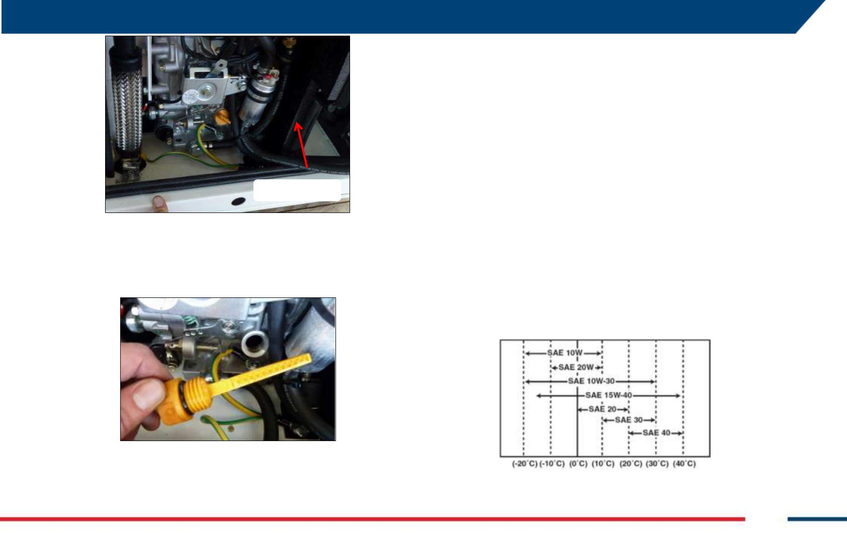
5 FIRST ArcSAR SETUP
IDS GeoRadar S.r.l. Confidential Information - Do Not Distribute MNG/2017/0016 Rev 1.0 49/ 78
Fig. 102 – Oil dipstick
fully reinsert the oil cap/dipstick without screwing it in;
remove the oil cap/dipstick and make sure the oil level is between
the MAX and MIN marks on the dipstick;
Fig. 103 – Oil dipstick indicator
if the oil level is too low, add some oil; a funnel should be useful;
wait one minute and check the oil level;
add more oil if necessary but don’t exceed the MAX level;
fully reinsert the oil cap/dipstick and tighten it;
turn on Genset Isolation Point switch and the GENSET switch on the
PSU, and test the generator.
1.1.1.1 Oil for ArcSAR Generator
Always use oil with suitable viscosity for the temperature where the engine
is being operated. Use the chart reported in Fig. 3.14 when choosing your
engine oil. The oil tank has a capacity of 1.1 liters. Besides, use an engine oil
that meets or exceeds the following guidelines and classifications:
API (American Petroleum Institute) services categories CD or higher;
ACEA (European Automobile Manufacturers Association) services
categories E-3, E-4 and E-5;
JSO (Japanese Automobile Standards Organization) services category
DH-1.
Fig. 104 – Service Grade Viscosity chart
Oil Dipstick
Confidential Information - Do Not Distribute
Be environmentally responsible. Follow these procedures for hazardous waste
disposal. Failure to follow these procedures may seriously harm the
environment.
Follow the guidelines of the government agency for the proper disposal of
hazardous materials such as batteries. Consult the local authorities or
reclamation sites;
Never dispose of hazardous materials irresponsibly by dumping them into a
sewer, on the ground or into ground water or waterways.
only use the recommended engine oil. Other engine oils may affect
warranty coverage, cause internal engine components to cease and
shorten the engine life;
prevent dirt and debris from contaminating the engine oil. Carefully clean
the oil cap /dipstick and the surrounding area before removing the cap;
never mix different types of engine oil. This may adversely affect the
lubricating properties of the engine oil;
never overfill. Overfilling may result in white exhaust smoke, engine
overspeed or internal damage;
always keep the oil level between the upper and lower lines in the oil.
5.12.2 Fuel refill
check the fuel level pushing the button of the fuel level indicator (red
in Fig. 105 left). If the fuel level in the tank is low (indicator on left),
refill the tank through the black filler under the indicator (green in Fig.
105 left);
Fig. 105 – Fuel Tank side
5.12.3 Drain air in fuel circuit
During first IBIS-ArcSAR installation, it should be necessary to remove the
air from the fuel filter inside the generator. To do this, it is necessary to
open the generator panel (Fig. 106 left), unlocking the two spring-locks.
Looking on the left, push the black button to activate a pump primer (Fig. 106
right). Wait until hearing a bleeding sound from fuel filter (
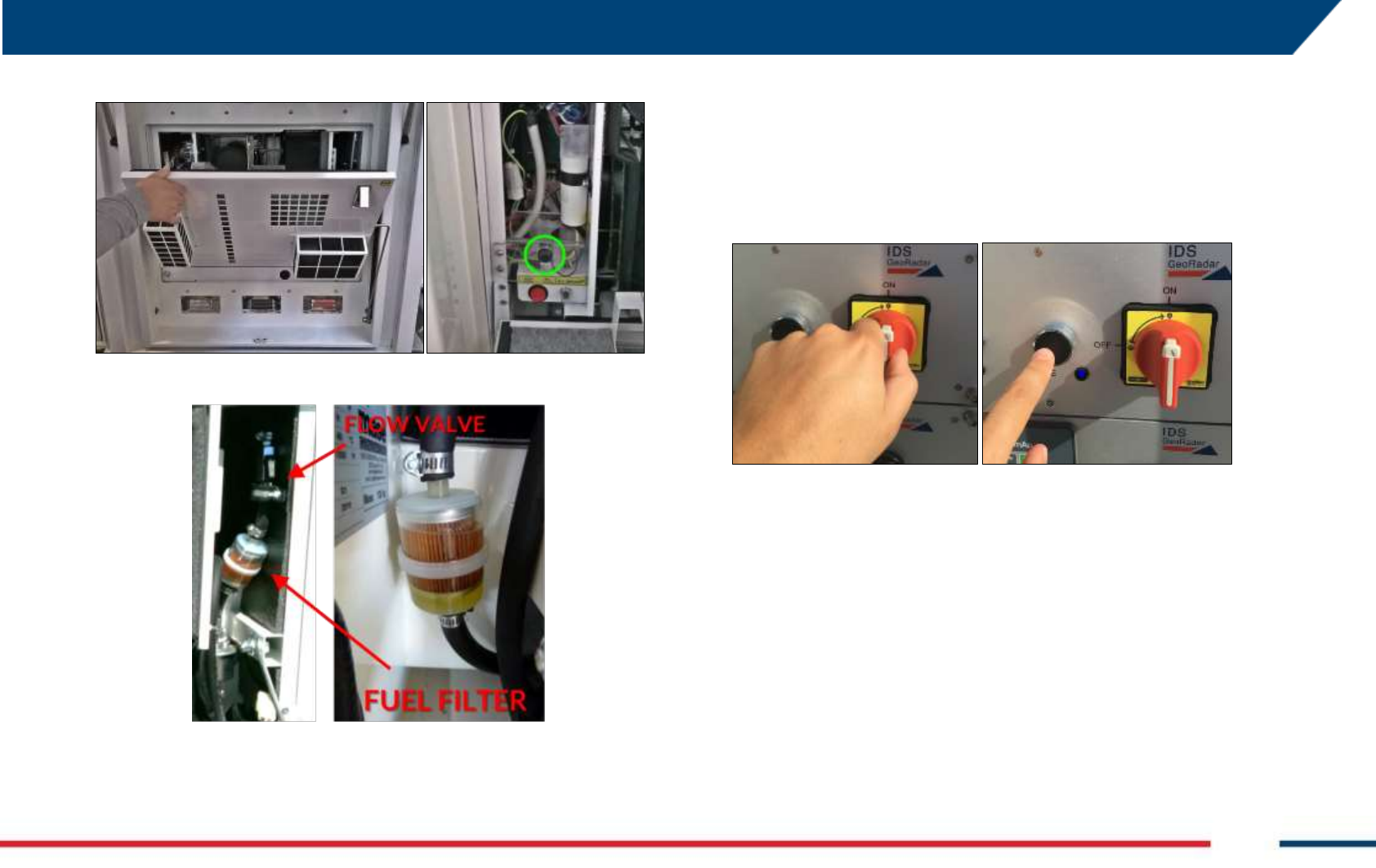
5 FIRST ArcSAR SETUP
IDS GeoRadar S.r.l. Confidential Information - Do Not Distribute MNG/2017/0016 Rev 1.0 51/ 78
Fig. 107).
Fig. 106 – Fuel filter cleaning
Fig. 107 – Fuel filter
Check if the red switch placed under the black button is on I position.
5.13 Turning on the system
Turn the red switch on and push the Enable switch (Fig. 108). With this
actions, the Power, Control and Green modules will be supplied (the
Module On LED has to be lit up).
Fig. 108 – Turning on the system
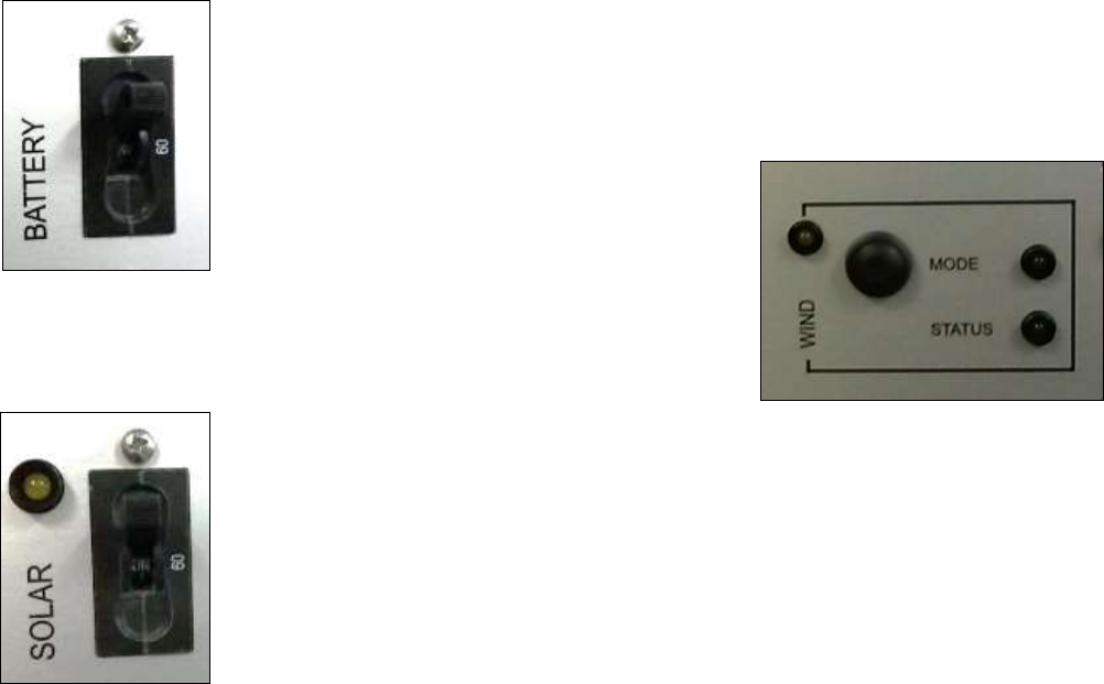
5.14 Green module first setup
Follow the steps below to properly turn on the solar panels and/or the wind
turbine.
Turn on the BATTERY toggle switch (Fig. 109) to allow the power
generated by the green sources to flow to the ArcSAR batteries.
Confidential Information - Do Not Distribute
Fig. 109 – BATTERY switch on the GREEN module
Turn on the SOLAR toggle switch (Fig. 110) and check if the LED is lit
up;
Fig. 110 – SOLAR switch on the GREEN module
If the Wind Turbine is present:
Once the SYSTEM switch has been turned on, the MODE LED is lit up
and solid, while the STATUS LED is off. In this condition, the wind
turbine is electrically braked, this it won’t provide any power to the
system;
To release wind turbine brake, push the black button for 10 seconds:
while pushing the black button the STATUS LED is blinking;
Once the brake is released the MODE LED is blinking and the STATUS
LED is solid;
The WIND LED is lit up once the wind turbine generates enough
power to charge properly the ArcSAR batteries.
Fig. 111 – WIND controls on the GREEN module
Once the PSU Isolation Point switch is off the Wind Turbine is automatically
braked.
In any case it’s possible to brake the Wind Turbine blades manually:
To brake the wind turbine blades, push the black button for 10
seconds: while pushing the black button the STATUS LED is blinking;
If the blades are braked, the MODE LED is solid, while the STATUS
LED is off;
5.15 ArcSAR Sensor first set up
On the Control module of the PSU, turn on the SENSOR and CAMERA
switches. The corresponding LEDs on the positioner will lit up in blue (Fig.
119)
5 FIRST ArcSAR SETUP
IDS GeoRadar S.r.l. Confidential Information - Do Not Distribute MNG/2017/0016 Rev 1.0 53/ 78
5.16 ArcSAR Positioner first set up
On the Control module of the PSU, turn on the POSITIONER AND GPS
switches. The corresponding LEDs on the positioner will lit up in blue (Fig.
119)
Fig. 112 – Positioner LEDs
The communication between the Positioner and IBIS Controller application is
provided using serial connection. The default port is COM7
MIND YOUR HEAD
Positioner is automatically controlled by IBIS Controller and it is able to rotate
by itself. Pay attention while working under the Positioner to the tack
movement. Every movement of the Positioner is pointed out by an intermittent
acoustic sound and a blinking yellow lamp.
5.17 ArcSAR Laptop first setup
1. open the Laptop sliding drawer placed under the PSU modules. To
extract the Laptop PC drawer unscrew the knob on the right (red)
and using the handle (green), pull out the drawer (Fig. 113);
Fig. 113 – Unscrewing PC drawer black knob
2. On the drawer the following connection cables are present: Laptop
supply, radar sensor Ethernet, system Ethernet, USB and serial port
cable (Fig. 114).
Fig. 114 – Connections on the PC drawer
3. the Laptop PC is provided in its own cardboard box, together with the
Laptop Power Supply cable, the Laptop Manual and Recovery Disc;
4. place the Laptop on the drawer: two plastic pivots are present to
ensure the fastening of the machine. Insert the two pivots into the
Confidential Information - Do Not Distribute
two holes placed at the corner of the bottom side of the laptop. Then
connect all the cables;
Fig. 115 – CF31 with cables connected
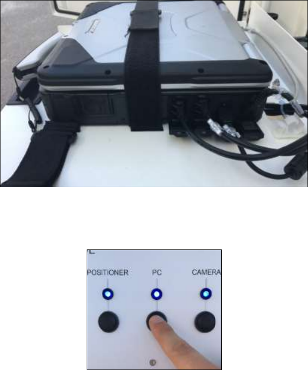
5. To supply the Laptop turn on the PC switch on the Control Module.
The Laptop will turn on automatically;
Fig. 116 – PC Switch on Control Module
6. to close the tray, push the drawer inside the compartment and screw
the black knob on the right again (Fig. 22). Remember to fasten the
Velcro® belt on the CF31, in order to keep stuck the computer during
ArcSAR moving.
5.18 ArcSAR IP addresses configuration
In case of integration of the ArcSAR devices into the mine network, the IP
addresses have to be configured again.
It is recommended to perform these actions with the assistance of an IBIS
Specialist.
The devices that need to set an IP address are:
Power Supply Controller;
Pointing Camera;
Weather Station internal Data Logger board (if present);
Wi-Fi Radios (if present);
ArcSAR Laptop.
5.18.1 Power Supply Controller IP address
1. Click on Start and run Lantronix → DeviceInstaller as administrator;
2. wait some seconds to let the software visualize all the components
connected. On the main big tab, select the device whose IP has to be
assigned;
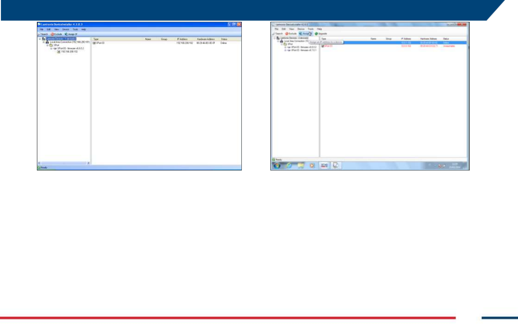
5 FIRST ArcSAR SETUP
IDS GeoRadar S.r.l. Confidential Information - Do Not Distribute MNG/2017/0016 Rev 1.0 55/ 78
Fig. 117 – Lantronix DeviceInstaller screen
3. click on Assign IP and a new window will open;
Fig. 118 – Lantronix Assign IP
4. in Assignment Method Tab, select Assign a Specific IP Address and
click on Next;
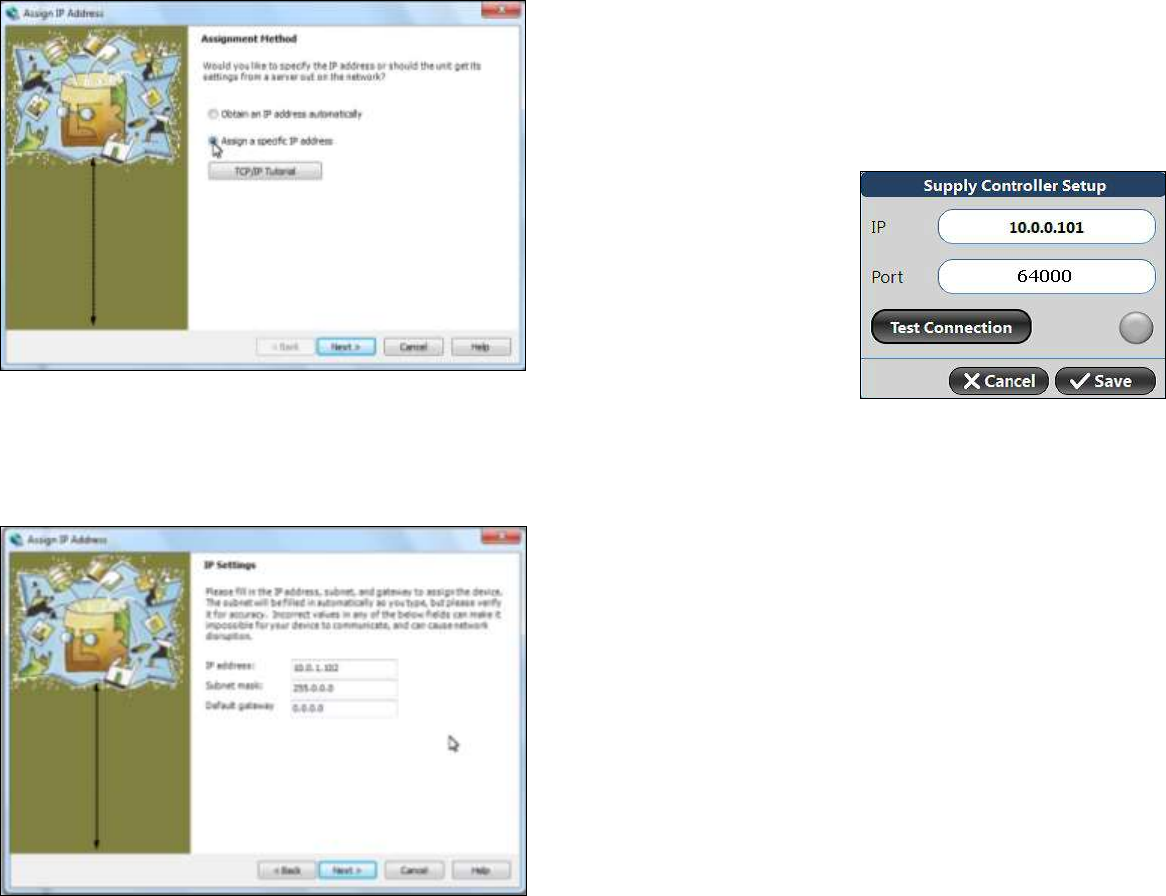
Confidential Information - Do Not Distribute
Fig. 119 – Lantronix DeviceInstaller: Assignment Method
5. in IP Settings Tab, complete the three field (IP Address, Subnet Mask
and Default Gateway) with the specific device addresses and click on
Next;
Fig. 120 – Lantronix DeviceInstaller: IP Settings
6. in the final Assignment Tab click on button Assign to complete the
operation. Then close Lantronix;
7. check the right assignment of the device IP directly on Controller
software: Settings > Supply > Supply Controller Setup > insert the IP
PSC address > Test Connection.
Fig. 121 – Supply Controller Setup
5.18.2 Pointing Camera IP address
To change the IP address of the Pointing Camera, open the browser and
access the related Hikvision application webpage. The default IP address is
10.0.0.105.

5 FIRST ArcSAR SETUP
IDS GeoRadar S.r.l. Confidential Information - Do Not Distribute MNG/2017/0016 Rev 1.0 57/ 78
Fig. 122 – Hikvision login page
insert admin as User Name and ibis12345 as password and click Login
(Fig. 122);
select Configuration and on the column on the left column select
Network;
insert the new IP address, Selection mask and Default gateway (Fig.
123);
Fig. 123 – Hikvision configuration page
close Internet Explorer;
change the IP address of Pointing Camera in IBIS Controller settings.
For any further details refer to IBIS Controller User Manual [BD1].
5.18.3 Weather Station internal Data Logger board IP address
To change the IP address of the internal Weather Station board, open the
browser and access the related application webpage. The default IP address
is 10.0.0.104.
In the WeatherLink IP Configuration page, tick the field Use the following IP
Address and assign the desired IP Address with the related Selection Mask
and Default Gateway. Do not change anything in the right part of the
window. (Fig. 124).
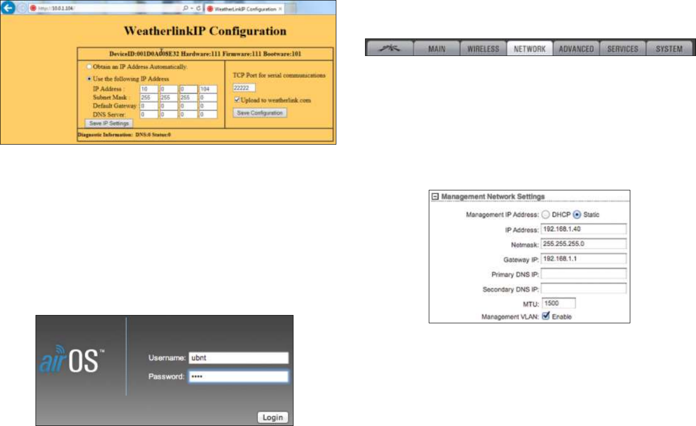
Confidential Information - Do Not Distribute
Fig. 124 – WeatherLink IP configuration page
Press Save IP Settings to confirm and close Internet Explorer.
Change the IP address of Weather Station in IBIS Controller settings. For
any further details refer to IBIS Controller User Manual [BD1].
5.18.4 Wi-Fi Radio IP address
To change the IP address of the Wi-Fi radios, open the browser and access
the related AirOS application webpage. The default IP address is 10.0.0.106.
Fig. 125 – AirOS login page
insert ubnt as User Name and Password and click Login (Fig. 125);
select Network on the upper taskbar to access the network
configuration page;
Fig. 126 – AirOS taskbar
set the Network Mode as Bridge;
set the Configuration Mode as Simple;
in Management Network Settings, tick Static in the Management IP
Address;
change the IP address, Subnet mask and Default gateway, modifying
the related fields (Fig. 127);
Fig. 127 – AirOS: Management Network Settings
click on Change button, placed at the lower right corner of the screen
to save the settings and close the AirOS application.
5.18.5 ArcSAR Laptop IP address
To change the IP address of the CF31 ArcSAR Laptop, follow the steps
below:
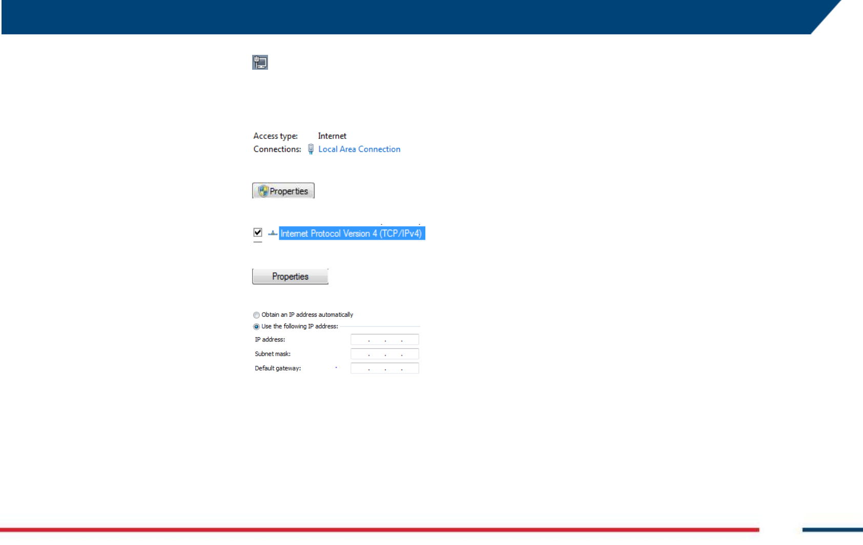
5 FIRST ArcSAR SETUP
IDS GeoRadar S.r.l. Confidential Information - Do Not Distribute MNG/2017/0016 Rev 1.0 59/ 78
- go on the Windows taskbar;
- right click on the Network icon;
- access Open Network and Sharing
Center;
- open the Local Area Connection
link;
- open Properties;
- select Internet Protocol Version 4;
- click on Properties;
- tick Use the following IP address
and insert the new IP address,
Subnet mask and Default gateway.
Then click OK
- reboot the computer
5.19 Controller General Settings
Before starting the setup for a new IBIS-ArcSAR session, it is recommended
to take possession of:
Digital Terrain Model (DTM) of the scenario to monitor. IBIS
Controller accepts following file formats: .dxf, Shapefiles, .xyz or
ASCII grid (.txt);
the EPSG code which is a unique value used to unambiguously
identify projected, unprojected, and local spatial coordinate system
definitions;
the IP address of IBIS Guardian software and the type of data transfer
(TCP or FTP).
For any further details, please refer to the IBIS Controller User Manual
[BD1].
5.20 End of the ArcSAR First Setup
To complete the first setup, turn off the PSU and GENSET Isolation Point
switches
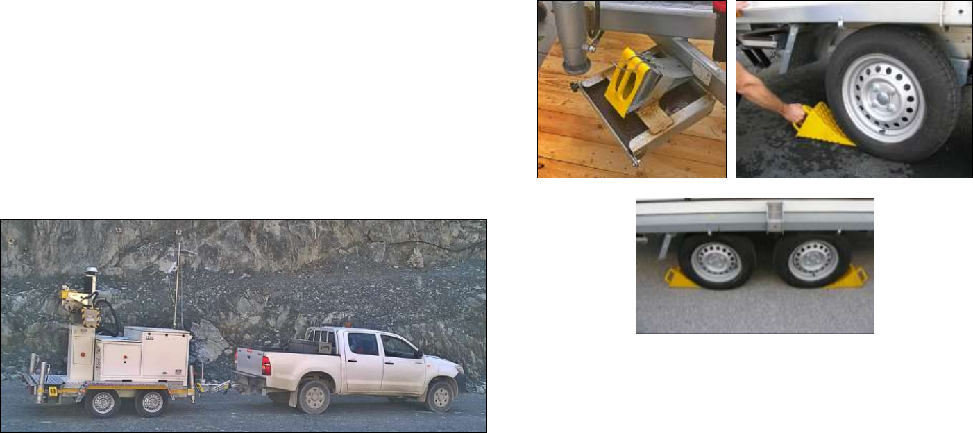
Confidential Information - Do Not Distribute
6 FIRST IBIS-ArcSAR START UP
6.1 Park the IBIS-ArcSAR
This part describes the procedure to park and stabilize the Trailer:
Move the trailer to the site from where the monitoring will be
performed (Fig. 128)
park the trailer, reminding that front side of the ArcSAR (Acquisition
Unit) has to face the area to be monitored;
Fig. 128 – Moving the IBIS-ArcSAR
6.2 Disconnect the IBIS-ArcSAR from the truck
6.2.1 Set wheel chocks
slip off yellow chock levels which are placed at the corners in the
lower part of the cart. Blocking wheels with them to ensure cart
immobility during next steps (Fig. 129);
Fig. 129 – Set wheels chocks
6.2.2 Trailer hand brake
stabilize the trailer pulling hand brake (Fig. 130);
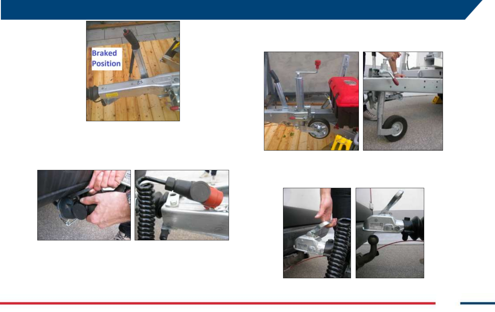
5 FIRST IBIS-ArcSAR START UP
IDS GeoRadar S.r.l. Confidential Information - Do Not Distribute MNG/2017/0016 Rev 1.0 61/ 78
Fig. 130 – Pulling hand brake
6.2.3 Disconnect trailer cable from the truck
disconnect the cable from the vehicle and connect it to the socket on
the cart (Fig. 131);
Fig. 131 – Disconnecting trailer cable
6.2.4 Disconnect IBIS-ArcSAR trailer from truck towing bar
lower the front wheel of the cart, turning handle counter-clockwise,
until the wheel touches the ground (Fig. 132). The side lever allows the
lifting of the wheel during transport operations;
Fig. 132 – Lowering the front wheel of the cart
disconnect the cart from the vehicle, lifting the handle vigorously as
shown in Fig. 133;
Fig. 133 – Disconnecting cart from the vehicle
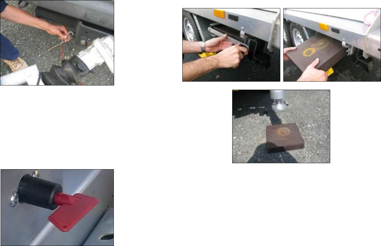
Confidential Information - Do Not Distribute
pull off the safety hook with the red wire (Fig. 134);
Fig. 134 – Removing safety hook
6.3 Hydraulic Jacks Setup
6.3.1 Turning on the jacks battery cut-off switch
insert the security key in its socket, placed on the cart shaft, and turn
it in vertical position (Fig. 135);
Fig. 135 – Hydraulic system battery cut-off switch
6.3.2 Plywood bases under jacks
remove plywood bases from their housings and put them under the
four cart hydraulic supports (Fig. 136);
Fig. 136 – Plywood bases setup
6.3.3 Open jack switches
unlock supports opening the four hydraulic valves from horizontal
position to vertical position (Fig. 137), in order to activate the moving
pistons;
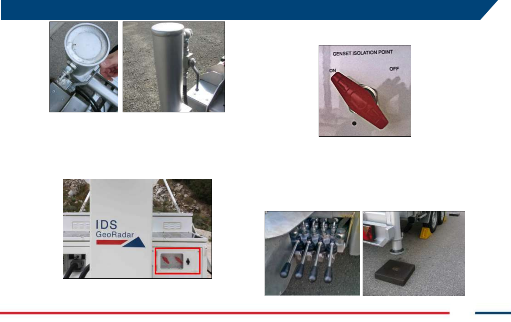
5 FIRST IBIS-ArcSAR START UP
IDS GeoRadar S.r.l. Confidential Information - Do Not Distribute MNG/2017/0016 Rev 1.0 63/ 78
Fig. 137 – Opening jack switches
6.3.4 Turning on the Genset Isolation point on the Supply Unit
open the Isolation Point panel on the front side of the ArcSAR (Fig.
138);
Fig. 138 – Isolation Point panel on Supply Unit front side
open the Isolation Point switchboard, turning the GENSET Isolation
Point switch on (Fig. 139);
Fig. 139 – GENSET Isolation Point switch turned on
6.3.5 Lower hydraulic legs
lower hydraulic legs (right side of the trailer) acting on the four black
pistons. Check the right drop of jacks over the plywood bases (Fig.
140);
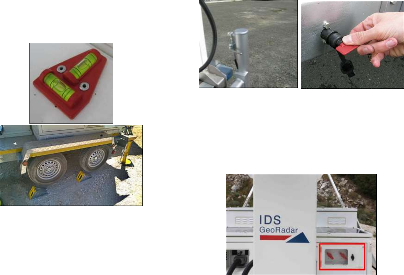
Confidential Information - Do Not Distribute
Fig. 140 – Jacks pistons
check the correct horizontal position of trailer observing spirit levels
placed on the left of the pistons. Verify that wheels are raised off the
ground (Fig. 141);
Fig. 141 – Right trailer horizontal levelling
6.3.6 Secure the jacks movement
close valves to lock again the four jacks, and turn the security key in
horizontal position to secure cart stability (Fig. 142).
Fig. 142 – Secure the jacks
6.4 Power Supply Unit setup
6.4.1 Turn on PSU Isolation point devices
open the Isolation Point panel on the front side of the ArcSAR (Fig.
143);
Fig. 143 – Isolation Points panel
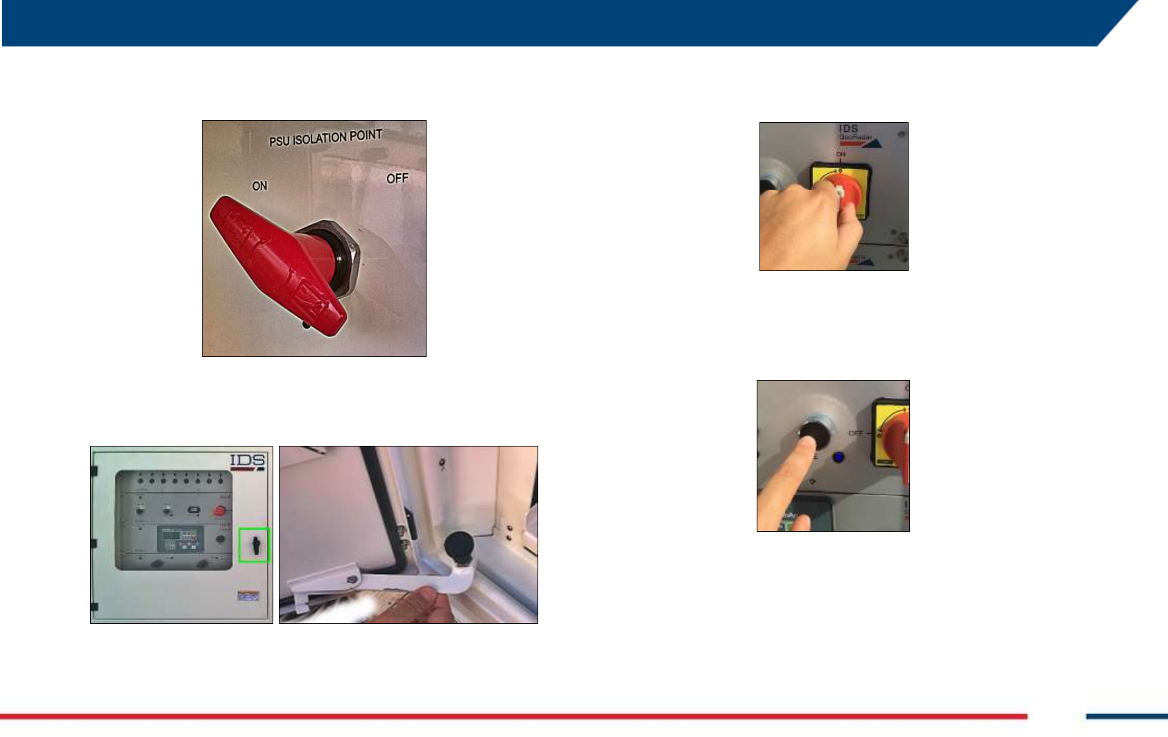
5 FIRST IBIS-ArcSAR START UP
IDS GeoRadar S.r.l. Confidential Information - Do Not Distribute MNG/2017/0016 Rev 1.0 65/ 78
turn the PSU Isolation Point switch on (Fig. 144);
Fig. 144 – PSU Isolation Point switch turned on
open the PSU door using the black handle (green). Secure the door
fixing it with the lever placed on the left lower corner (Fig. 145);
Fig. 145 – PSU panel
on the Power Module, turn the red switch to position ON (Fig. 146),
the battery indicator will show the battery’s level and the LED will
turn on;
Fig. 146 – Turning on the PSU ON/OFF switch
push the ENABLE and AC INPUT switches placed on the Power
Module. This operation switch on the Power Module, the Control
Module and the Green Module.
Fig. 147 – Turning on the ENABLE switch in the Power Module on PSU panel
If the mains AC input is available on site, the AC Mains cable has to be used
(Fig. 148 left). The blue end of this cable has to be plugged to the external
supply connection and the other end of the cable has to be plugged to the
Mains Input connection in I/O interface panel on the rear side of the IBIS-
ArcSAR (Fig. 148 right).
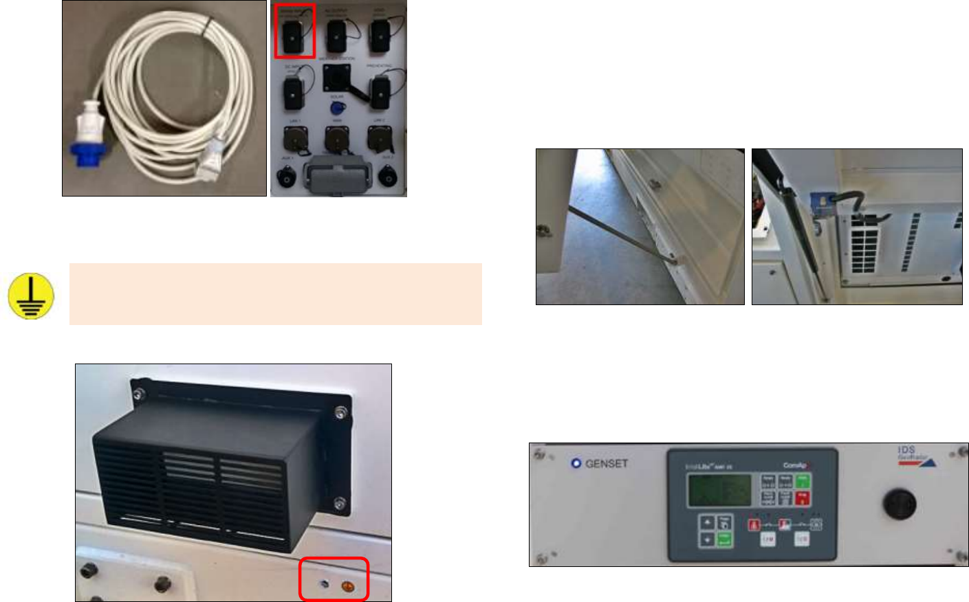
Confidential Information - Do Not Distribute
Fig. 148 – Connections to supply IBIS-ArcSAR with AC Mains power
Grounding connection is recommended for the IBIS-ArcSAR operation,
in order to protect the electrical devices of the equipment.
Earth pin is below the generator exhaust gas pipe (Fig. 149)
Fig. 149 – Grounding connection
6.5 Generator setup
Open the generator door and fix the panel with the rod placed on the
internal side of the door : the panel has to stay partially open while
the radar is functioning in order to improve ventilation (Fig. 150 left). If
the panel is left closed a sensor avoids the generator starting (Fig. 150)
giving an alarm on both AMF25 Unit and Controller software;
Fig. 150 – Generator panel setup
on the PSU front panel, turned on the GENSET switch placed in the
Control Module. In this way Genset Module will be supplied and the
AMF25® Control Panel will be switched on (Fig. 151).
Fig. 151 – Turning on AMF25 Control Panel
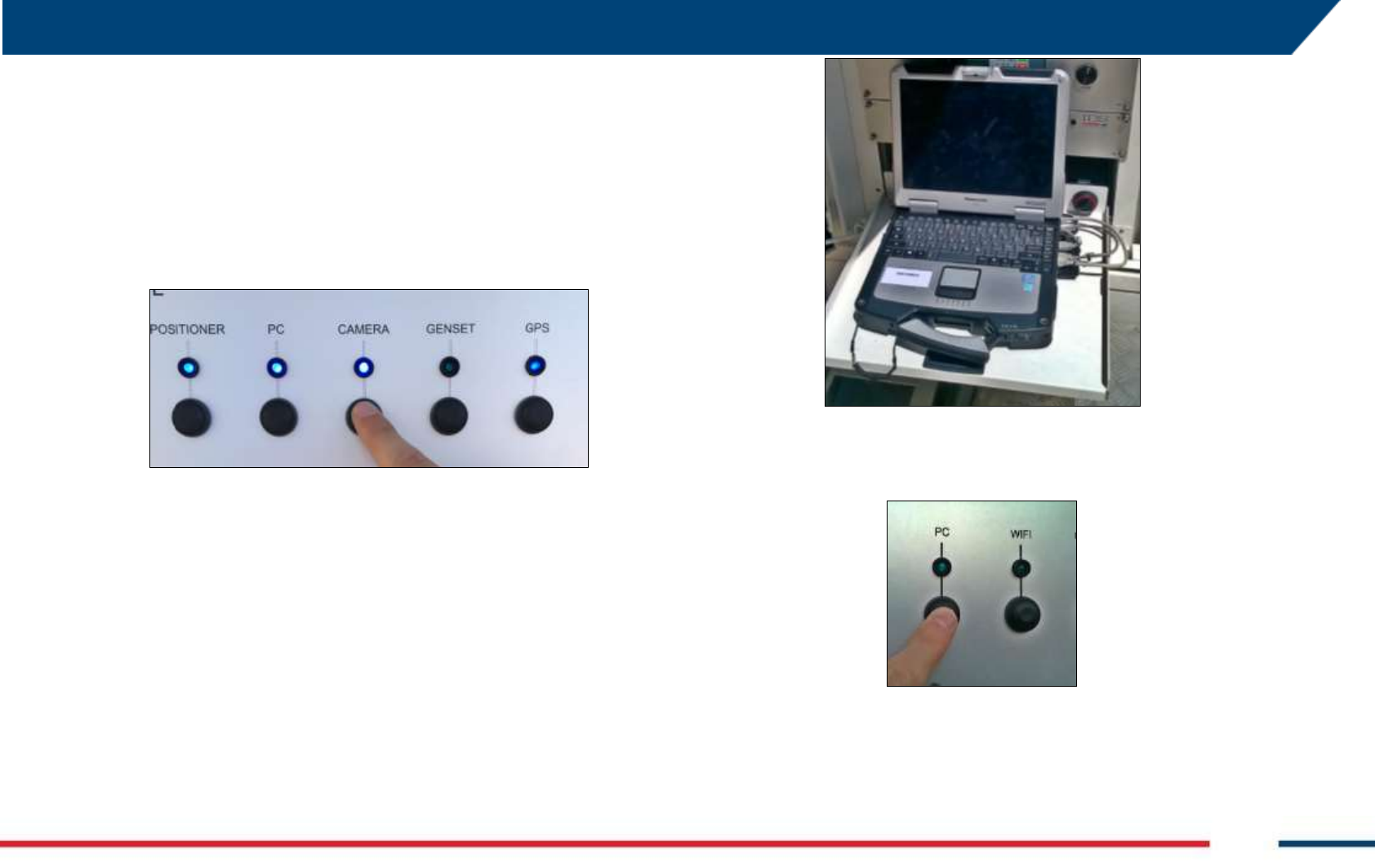
5 FIRST IBIS-ArcSAR START UP
IDS GeoRadar S.r.l. Confidential Information - Do Not Distribute MNG/2017/0016 Rev 1.0 67/ 78
6.6 Wind Turbine Setup
If the Wind Turbine has been installed as optional, repeat the setup steps
as described in the Paragraph 5.14.
6.7 Panoramic Camera Setup
To supply the Panoramic Camera, it’s necessary to open the PSU door and
turn on the CAMERA switch (Fig. 152).
Fig. 152 – Turning the CAMERA switch on (PSU Control module)
For the configuration of the Panoramic Camera during a new Controller
session wizard, please refer to the IBIS Controller User Manual [BD1].
6.8 Laptop Starting
1. open the Laptop sliding drawer placed under the PSU modules;
2. unscrew the knob on the right and pull out the sliding drawer;
Fig. 153 – CF31 laptop with cables connected
3. supply the Laptop turning on the PC switch on the Control Module
Fig. 154 – PC Switch on Control Module
4. the Laptop will be automatically turned on. Wait the loading of the
Operating System and the loading of the IBIS Controller software. In
any case the software can be run clicking on its desktop icon.
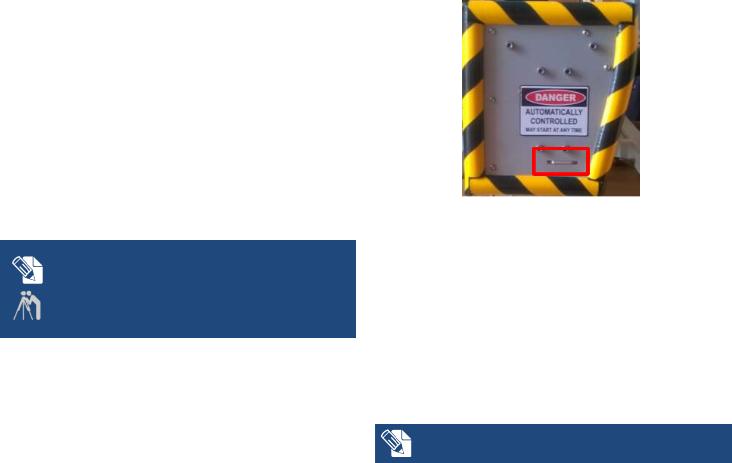
Confidential Information - Do Not Distribute
6.9 Session starting
Once the instrument with all its peripherals is installed according to
instructions, it is ready to be used. The following list describes the
operations requires to start up and use IBIS-ArcSAR:
1. make sure that SENSOR and POSITIONER switches are turned on;
2. make sure GPS switch is turned on;
3. turn on the other switches if the related components are present in
the system configuration. Remind that if the CAMERA and WIFI
switches are turned on, the related plugs are supplied by Power-
over-Ethernet.
At this point, a new session can be created on the IBIS Controller
application and the instrument can be used following the instructions
provided in the IBIS Controller User Manual [BD1].
ArcSAR POSITION SURVEYING
The IBIS-ArcSAR is provided with the integrated GPS. The surveying of the
ArcSAR position will be performed automatically during a new session wizard.
It is mandatory to set the EPSG code in the Controller Settings.
The ArcSAR position can also be evaluated surveying the two little sliding
plates placed at the ends of the Positioner (Fig. 155) and then calculating the
middle point of the Positioner. This surveying has to be done with the
Positioner at 0° azimuth (Scanner parallel to the shorter trailer side).
Fig. 155 – Sliding plates to survey Positioner
7 DISMANTLING AN IBIS-ArcSAR SYSTEM
7.1 Actions on IBIS Controller and on ArcSAR Laptop
Stop the running Controller session, clicking on the STOP button
(refer to the IBIS Controller User Manual [BD1]);
close the IBIS Controller application;
the software will ask to move the IBIS-ArcSAR Positioner to the
Transport Mode. It is mandatory to click Yes. Wait the end of the
movement of the ArcSAR Positioner;
During the transportation of the IBIS-ArcSAR, the Positioner has to be set on
Transport mode ().

5 DISMANTLING AN IBIS-ArcSAR SYSTEM
IDS GeoRadar S.r.l. Confidential Information - Do Not Distribute MNG/2017/0016 Rev 1.0 69/ 78
shut down the Laptop and secure it using the Velcro® strap, in order
to ensure its immobility during ArcSAR transportation.
7.2 Actions on the ArcSAR Supply Unit
If the Wind Turbine is present it’s mandatory to brake its blades:
If the Wind Turbine is running, the MODE LED is lit up and blinking
and the STATUS LED is lit up and solid;
To brake the wind turbine blades, push the black button for 10
seconds: while pushing the black button verify that the STATUS LED is
lit up and blinking;
If the blades are braked, the MODE LED is lit up and solid, while the
STATUS LED is off;
Turn off the red isolation point switch placed on the Power module of the
PSU.
Turn off the PSU Isolation Point switch placed on the front side of the
Supply Unit.
7.3 Actions on the Trailer jacks
Put the yellow chocks around the trailer wheels (Fig. 129);
turn on the battery cut-off switch placed on the trailer shaft, turning
it with the specific key (Fig. 135);
unlock supports opening the four hydraulic valves from horizontal
position to vertical position (Fig. 137), in order to activate the moving
pistons;
raise hydraulic legs acting on the four black pistons. Check the right
lift of jacks over the plywood bases (Fig. 140);
remove the plywood bases and placed them in the specific housings;
lock the jacks closing the four hydraulic valves from vertical to
horizontal position;
turn off the GENSET isolation point placed on the front side of the
Supply Unit (Fig. 143);
turn off the battery cut-off switch placed on the trailer shaft, turning
it with the specific key.
7.4 Get ArcSAR ready to drive
Close and lock all the ArcSAR panels and doors;
connect the cart to the vehicle, lifting the handle vigorously on the
car hook. A click sound will point out the right connection between
the car hook and the trailer (Fig. 133);
raise the front wheel of the cart, turning handle clockwise, until the
wheel doesn’t touches the ground anymore. The side lever allows the
lifting of the wheel during transport operations (Fig. 132);
connect the cable to the vehicle and connect it to the socket on the
car (Fig. 131);
pull on the safety hook with the red wire (Fig. 134);
release hand brake;
at this point, it is possible to move IBIS-ArcSAR safely.

Confidential Information - Do Not Distribute
APPENDIX A DISCLAIMER
1. Generals.
i. The present Disclaimer applies to all products (the “Products”) designed,
produced and distributed by IDS GeoRadar s.r.l. ,its Subsidiaries, Affiliated and
authorized Distributors. IDS GeoRadar s.r.l. reserves full ownership and
intellectual property rights of any “Information” contained in this Disclaimer
including Trade Marks and Graphics. No part of this Disclaimer may be used or
reproduced in any forms without the prior written agreement of IDS GeoRadar
s.r.l..
ii. In the event that any provision of this Disclaimer may be invalid, unlawful or
incapable of being enforced by a rule of law, all other provisions shall,
nonetheless, remain in full force and effect. Failure to either enforce or exercise
any right, privilege, or legal remedy at any time, any provision contained in this
Disclaimer, shall not be deemed a waiver of such provisions or right, remedy, or
privilege.
iii. This Disclaimer shall be interpreted, governed, construed and enforced in
accordance with the laws of Italy. Buyer hereby consents to the exclusive
jurisdiction of Pisa.
2. Initial Precautions for Setting-up and Use of the Products.
i. The Buyer, for setting-up and using the purchased Products, shall consult the
official documentation provided by IDS for the Products (“Reference
Documentation”) and carefully ascertain the compliance with national laws and
requirements, which may limit or even forbid their use.
ii. For Products which shall operate by circulation in Public Areas/Roads, with or
without moving traffic, Buyer/User shall verify the approval of local authority
and/or site’s owner according to their specific procedures. IDS shall not be liable
for any direct, indirect, special, incidental or consequential damages or injuries,
including without limitation, lost revenues or lost profits, resulting by un-
authorized use of the Products in Public Areas/Roads.
iii. For IBIS Products Family, Buyer/User warrants:
that these Products are not being used, in the design, development,
production or use of chemical, biological, nuclear ballistic weapons. Buyer/
User will defend, indemnify and hold IDS harmless against any liability
(including attorney’s fees) for non-compliance with the terms of this article.
that no operation or use of the IBIS products shall be started before its
designated Operator/s has got the IBIS User Certificate, as defined by IDS
GeoRadar s.r.l. specific procedure which the Buyer confirms to know and
accept.
iv. For Products which include specific “Operational” software with automatic data
processing and analysis “Tools”, i.e. the IBIS Products, User shall be aware that
the results provided by these “Tools” may be not error free. User that
completely relies on the outcomes provided by these Tools only, does it at his
own risk.
v. In no event IDS GeoRadar s.r.l. shall be liable for special, direct, indirect,
incidental, exemplary, punitive or consequential damages including, but not
limited to, loss of profits or revenue, caused by the use of the Products, either
separately or in combination with other products or relied upon the results
provided by the above “Tools”.
3. Disclaimer for the “Use” of the Products.
i. The User shall follow the instructions provided by IDS GeoRadar s.r.l. in its
official “Reference Documentation” for the Product, in particular the User’s
Technical Manual which contains all the specific steps and recommendations for
a correct setting-up and use of the Product.
ii. In no event IDS GeoRadar s.r.l. shall be liable for special, direct, indirect,
incidental, exemplary, punitive or consequential damages including, but not
limited to, loss of profits or revenue, caused by the missed or incomplete
observance of the instructions and prescriptions for the use of the Products,
either separately or in combination with other products, in particular for the
following main aspects:
a. Use of IDS GeoRadar s.r.l. Products outside its limitation of use, without
proper and adequate scientific/technical knowledge or without specific
training.
b. Use of results/outcomes of the measurements performed by the Product
aimed to safety aspects without using adequate control procedures and
assessment by skilled personnel.
c. Opening of the Equipment (for HW Products) without express written
authorization of IDS GeoRadar s.r.l.;
d. Unauthorized changes and additions to the Products.
e. Use of the Products connected to suspected non-working equipment or
with equipment (mainly PC) having characteristics non in compliance with
the required specifications of IDS not expressly authorized by IDS
GeoRadar s.r.l.;
f. Poor or faulty operation of the electrical and telecommunication networks
not directly managed by IDS GeoRadar s.r.l. or its delegates.

APPENDIX A. Disclaimer
IDS GeoRadar S.r.l. Confidential Information - Do Not Distribute MNG/2017/0016 Rev 1.0 71/ 78
g. Poor or faulty operation Software/Hardware of the third parties connected
with IDS GeoRadar s.r.l. Equipment.
h. Poor or faulty operation of the Products due to Software Virus which
infected the Products after their delivery.
i. Use of the Products which have encountered suspected manumissions,
accidents, electrostatic shocks, flashes, fire, earthquake, flooding or other
natural disasters or unexpected events.
j. Use or storage of the Products outside the limits of the “Operational
Temperature Range” specified by IDS GeoRadar S.r.l.
4. Disclaimer for the “IBIS Family” Products.
i. IBIS Products include specific “Operational” software with automatic data
processing and analysis which may give outcomes/results for helping User in the
monitoring of “the stability conditions” of a specific event.
ii. Nevertheless, IDS GeoRadar s.r.l. has the obligation to remind the Users that the
performance of IBIS might be influenced by two main factors which may distort
its outcomes, thus giving rise to false or missing alarms:
a. the parameters introduced by the operator/s.
b. the particular environmental conditions: (even though the radar
technology employed by IBIS, is deemed among the most reliable for the
monitoring of “instable slopes).
iii. Therefore, when IBIS Products are used in “Critical Monitoring for safety
purposes” applications, like real time monitoring of unstable slopes including
Opencast Mining, User must be aware that the “the assessment of the stability
conditions of the observed targets” must be tasked to skilled and certified
operator/s able to understand data supplied by either IBIS or other equipment
employed to such purpose; only operators officially trained and regularly
updated by IDS (holding an “IBIS User Certificate” thereof) are allowed to use
IBIS products.
IDS GeoRadar S.rl.. assumes no liability for any direct, indirect special, incidental or
consequential damages or injuries caused by such reliance or for the use of IBIS
Products by operator not holding an “IBIS User Certificate” issued by IDS GeoRadar
S.r.l.. Any Buyer or User that completely relies on information obtained from the
automated data processing/analysis tools only does so at his own risk and possible
damages caused to IBIS products during operations performed by not-certified
operators are not covered by the applicable Warranty Terms in force.
Confidential Information - Do Not Distribute
APPENDIX B WARRANTY
A. Standard Warranty Conditions
1. IDS GeoRadar s.r.l., (hereinafter referred to as IDS or Seller), warrants that its products
shall be free from defects in material and workmanship, for a period of 12 months from
the delivery date duly registered and certified (“Effective Date”) in the “Warranty
Registration Form” enclosed hereto. IDS shall repair or replace Products or parts
thereof found faulty (the “Faulty Parts”) which are returned to IDS, and which, at IDS’s
judgment, were defective or became defective during its normal use. Seller’s
obligations shall not apply to Faulty Parts that:
(a) Buyer do not properly store, install, use, or maintain;
(b) Buyer modify, or perform tests which are not approved in writing by the Seller;
(c) Buyer have subjected to any kind of misuse, detrimental exposure beyond its
intended purpose or damaged in an accident or by natural disaster or
calamities.
(d) Are repaired by other than IDS personnel; in which have been installed HW/SW
accessories not supplied by IDS; are integrated or connected to equipment
different from the ones supplied by IDS (except the PC data Logger conform to
IDS specifications);
(e) Whose operational software was not installed as per IDS instruction (see IDS
User’s Guide for the Data Acquisition Software);
2. Seller’s Products may include specific “Operational” software with automatic data
processing and analysis tools (SW) supplied under a License agreement (EULA). While
every effort is made to ensure the accuracy of the information/results provided by
these tools, they must not be intended as a substitute for people analysis; rather, they
have to be intended as an advisor and the user must not completely rely on the results
provided by them. Under no circumstances does IDS warrant that the SW will operate
uninterrupted or error free The SW is provided “as is” without warranty of any kind. IDS
warrants for a period of sixty (60) days from the Effective date that, under normal use,
the SW support media will be free of defects in material and workmanship; in such case
the provisions of above point a) apply
3. Any different warranty, granted by the Buyer to its retailers and clients, even as final
consumers, pursuant to the European Union law in force regarding the rights of the
consumers, does not engage IDS in anyway.
4. The above mentioned warranty excludes any other remedies and it has to be
considered the only and exclusive remedy foreseen for the Buyer and its retailers and
clients, with reference to IDS Products purchase, being, expressively understood that
any kind of limitation and/or discharge of responsibility provided by the present
warranty is referred to both (I) the responsibility as against any third parties, pursuant
to the legislation regarding the producer responsibility and (II) the warranty provided
by the law in force.
B. Warranty Procedure
1. To proceed in the application of warranty terms, Buyer shall have to contact IDS
Customer Care Office to get the clearance to return the Faulty Parts.
2. The Faulty Parts once received by IDS will be inspected to verify they are eligible for
repair or replacement..
3. Buyer is responsible for ensuring that the Faulty Parts be returned to IDS with a suitable
packing (it is recommended that the original packing be saved for a better understand
of the failure cause); IDS will not be obliged to repair or replace Faulty Parts damaged
from abuse, misuse, negligence, accident loss or damage in transit.
4. The Shipping costs for Products returned during the warranty period, are as follows:
(f) From Buyer Site to Seller site shipping costs, as per Incoterms CIP, are
borne by Buyer
(g) From Seller Site to Buyer site shipping cost, as per Incoterms CIP, are borne
by Seller
5. The warranty period on the repaired or replaced Faulty Parts is 6 (six) months or the
unexpired portion of warranty on such Faulty Parts whichever date comes later.
C. Special Warranty Conditions for IBIS Products
Without prejudice to the Warranty terms defined in the above Clauses A and B, the
following special conditions apply to the IBIS products.
1. IDS offers to the Buyer, optionally, special Support and Maintenance Plans to be
performed along the life of the equipment. These plans set forth special Warranty
conditions which are detailed in the relevant options purchased.
2. IBIS Product Family is subject to export/import regulations as per EU export control
regime Council Regulation (EC) No. 428/2009 and successive amendments. The
category of exportation for IBIS F product family is 6A008.d. Buyer warrants that the
IBIS Products to be purchased: a) shall not be re-exported, directly or indirectly, outside
Buyer’s country in violation of any law or regulation or to embargoed or otherwise
restricted countries, b) shall not be used, in the design, development, production or use
of chemical, biological, nuclear ballistic weapons. It is Buyer’s responsibility to know the
law pertaining to export/import procedures in the country of destination of the
Products. Buyer will defend, indemnify and hold Seller harmless against any liability
(including attorney’s fees) arising out of Buyer’s failure to comply with the terms of this
article. Should the Authorities issue an export restriction which leads to the
cancellation of a purchase order already accepted by IDS, IDS only liability shall be to
return to Buyer any account paid without interests. Buyer shall comply with the laws
and procedures in force in the country of destination of the Products.

APPENDIX B. Warranty
IDS GeoRadar S.r.l. Confidential Information - Do Not Distribute MNG/2017/0016 Rev 1.0 73/ 78
3. IBIS can be used in Critical Monitoring for safety purposes applications, like real time
monitoring of unstable slopes including Opencast Mining. Buyer shall be aware and
agree that the assessment of the stability conditions of the observed target must be
tasked to skilled and certified operator/s able to understand data supplied by either
IBIS or others. The performance of IBIS can be, in fact, influenced either by the
parameters introduced by the operator/s or by particular environmental conditions
which may distort its outcomes, thus giving rise to false or missing alarms.
4. IDS assumes no liability for any direct, indirect special, incidental or consequential
damages or injuries caused by such reliance or for the use of IBIS Products by operator
who have not achieved a training course certified by IDS. Any person or entity that
completely relies on information obtained from the automated data
processing/analysis tools only or by operators who have not achieved a training course
certified by IDS, does so at his own risk
D. Limited Liability
Without prejudice to the exclusion of liability stated at the above Clause C.
1. Seller’s sole obligation and liability under this Agreement shall be limited to the repair
or replacement of the Product, or the refund of the purchase price at the Seller’s sole
option. This Article sets forth the sole and exclusive remedies for claims based upon
defects or nonconformity of the Products, whether the claim is on contract, warranty,
tort (including negligence), strict liability, or otherwise.
The cumulative liability of Seller, including its subcontractors or suppliers, for any and all
claims, including but not limited to claims based on Seller’s negligence of any degree, strict
liability, breach of contract, warranty, reliance on the accuracy, reliability, or timeliness of
the information provided by the SW, patents or otherwise, shall not exceed the sums cashed
by IDS for the purchased Products, which give rise to the claim, and any such liability shall
terminate upon the expiration of the warranty period.
h
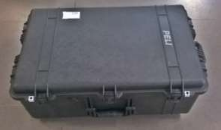
Confidential Information - Do Not Distribute
APPENDIX C PACKING CONTENTS
IBIS ArcSAR Acquisition Unit Box:
Wooden packaging - liftable with fork truck - (size: 184 x 113 x 249 (length
[cm] x width [cm] x height [cm] )) and total weight, when fully packed, of
495 kg). This box contains following parts:
The ArcSAR Positioner;
IBIS Supply Unit Box
Wooden packaging - liftable with fork truck - (size: 166 x 198 x 142 (length
[cm] x width [cm] x height [cm] )) and total weight, when fully packed, of
1200 kg). This box contains following parts:
The ArcSAR Supply Unit.
IBIS Trailer Unit Box
Wooden container - liftable with fork truck - (size 433 x 227 x 131 (length
[cm] x width [cm] x height [cm] )). This box contains following parts:
The ArcSAR Trailer;
The CF31 ArcSAR computer;
The metallic pole to install IBIS ArcSAR accessories;
The Generator Solar Panel and its metallic frame;
IBIS ArcSAR standard cables (see Paragraph 4.5);
IBIS ArcSAR standard spare parts (depending by the Customer
purchase);
The Wi-Fi radios (if they have been purchased as optional items);
The Weather Station Package (if it has been purchased as optional
item);
The Wind Turbine Installation Kit and its metallic pole (if it has been
purchased as optional item);
The IBIS Radar Sensor case (Fig. C. 1) (size 80 x 50 x 30 cm and total
weight - when packed - of 28 kg). This case contains the following list
of materials (Tab. C. 1):
Fig. C. 1 – IBIS Radar Sensor case
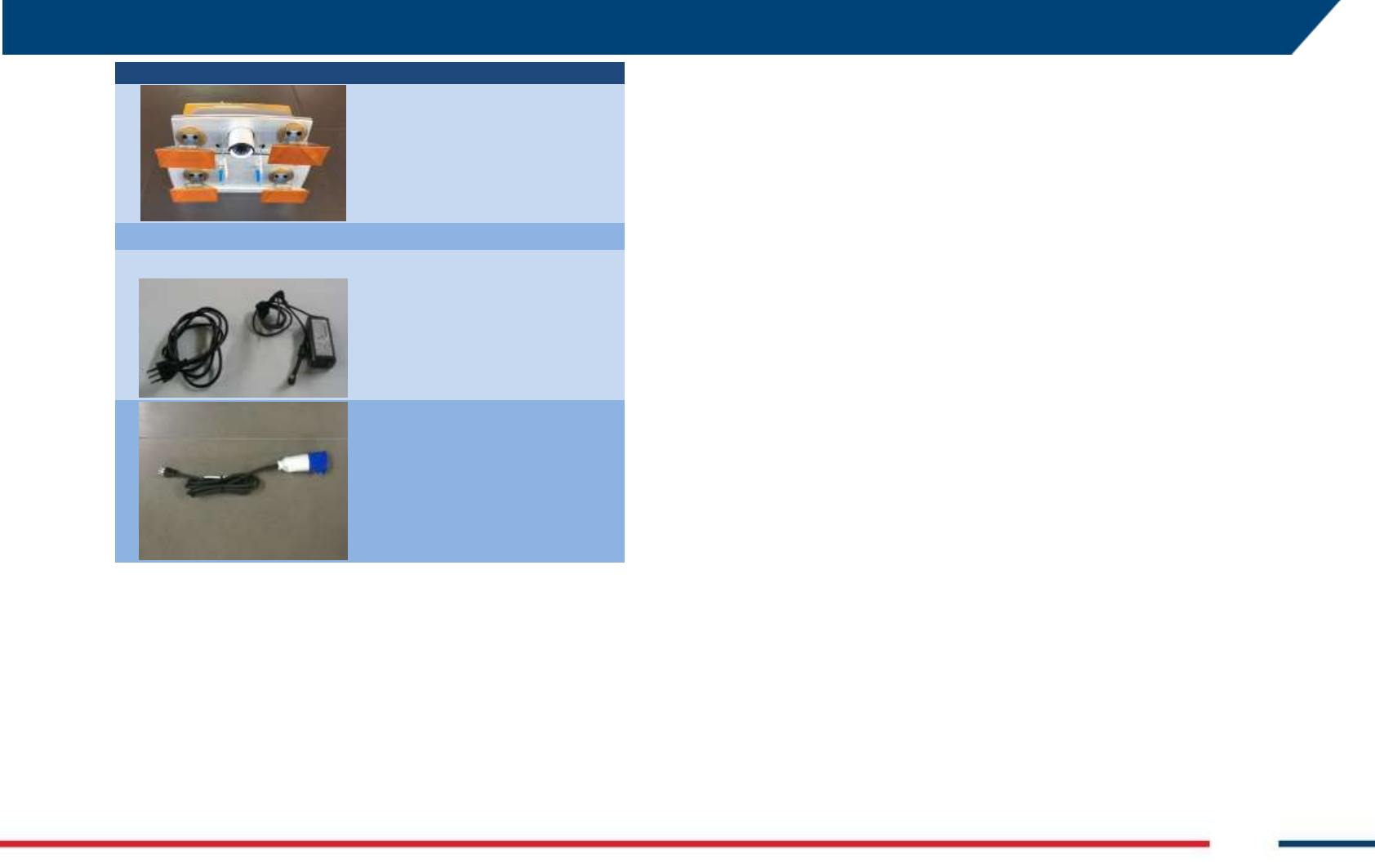
APPENDIX C. Packing Contents
IDS GeoRadar S.r.l. Confidential Information - Do Not Distribute MNG/2017/0016 Rev 1.0 75/ 78
PHOTO
DESCRIPTION
1 IBIS Radar Sensor
1 CF31 Laptop Supply cable
AC Mains cable (the cable has a different
plug depending to the destination country)
Tab. C. 1 – Contents of the IBIS Radar Sensor case
Confidential Information - Do Not Distribute
APPENDIX D ADDITIONAL NOTES
Authorization of utilization – national restrictions
European countries
IBIS products are classified by CEPT as SRD – Short Range Device - i.e. a
device that doesn’t cause interference to other systems operating in the
same frequency band. For details about IBIS products, apply the
recommendation ERC/REC 70-03 that defines the SRD equipment (annex 6,
frequency band l). Below is the link to the cited document:
http://www.erodocdb.dk/Docs/doc98/official/pdf/REC7003E.PDF
For Ku band system
Almost all the European countries have applied the ERC/70-30 for the Ku
band, however in some European countries, the use of IBIS system outside
a laboratory can still be subject to authorization by the Competent Ministry
of the country, where the system should be used. Please refer to the
Appropriate and Competent Ministry of the country to know whether it is
still necessary to get an authorization or not.
For X band system
Almost all the European countries have applied the ERC/REC 70-03 for the X
band system. Please refer to the Appropriate and Competent Ministry of
the country to know if there are some limitations in the utilization of X
band IBIS-FM equipment or not.
USA
The IBIS sensor is FCC certified, according to the FCC rule part 90, as a
radiolocation device (subpart F). In order to use the sensor in the US
territory, a license of utilization must be obtained by FCC. The licence
application can be submitted to the following website:
http://wireless.fcc.gov/uls/index.htm?job=home
According to Maximum Permissible Exposure requirements as defined
in FCC §1.1307 the Equivalent Isotropic Radiated Power of IBIS Sensor is
below the limit of 1mW/cm^2 at 20cm. Therefore, the minimum
distance to be kept with respect to the antennas during the acquisition
time, in order to meet MPE requirement, is 20cm.
For more information about licensing procedure contact IDS GeoRadar
personnel.
Canada
The IBIS sensor is IC certified as a licence exempt low power device,
according to RSS 210 annex 2. Operating band is 17.1 – 17.2 GHz, with a
maximum ERP power of 0.3 W. Respecting the mentioned limitation in
terms of band and emitted power, IBIS can be used in Canada, without any
license.
The sensor is configured in the factory considering the country of origin
of its customer. If monitoring activities are planned outside that
country, different settings shall be applied on request, for the duration
of the survey. Contact IDS GeoRadar personnel to change the settings
and restore them if re-entering the country of origin.
CE Marking
This equipment is in compliance with the essential
requirements and other relevant provisions of
Directive RED 2014/53/UE.
The full Declaration of its Conformity can be found
either on the CD or a separate document included with
this product.
This is a Class A product. In a domestic environment it
may cause radio interference. If so, the user may need
to take adequate measures.