IDS GeoRadar s r l IBIS-LS IBIS-L Linear Scanner User Manual MN 2009 070 11 manuale IBIS L PPR france FC cust
IDS Ingegneria dei Sistemi SpA IBIS-L Linear Scanner MN 2009 070 11 manuale IBIS L PPR france FC cust
UserManual.wiki
>
IDS GeoRadar s r l
>
IBIS LS User Manual
User Manual
Navigation menu
Upload a User Manual
Namespaces
Wiki Guide
HTML
PDF
Info
Views
User Manual
Discussion / Help
Navigation


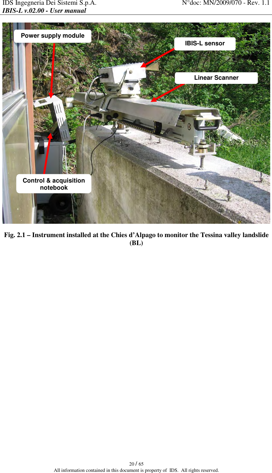
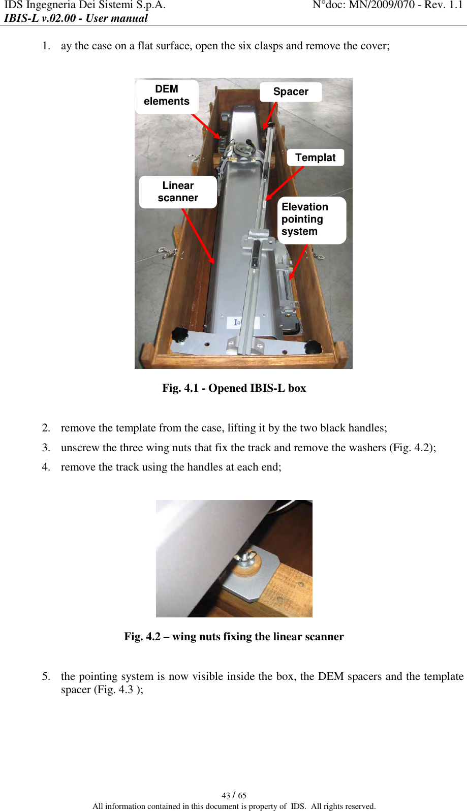
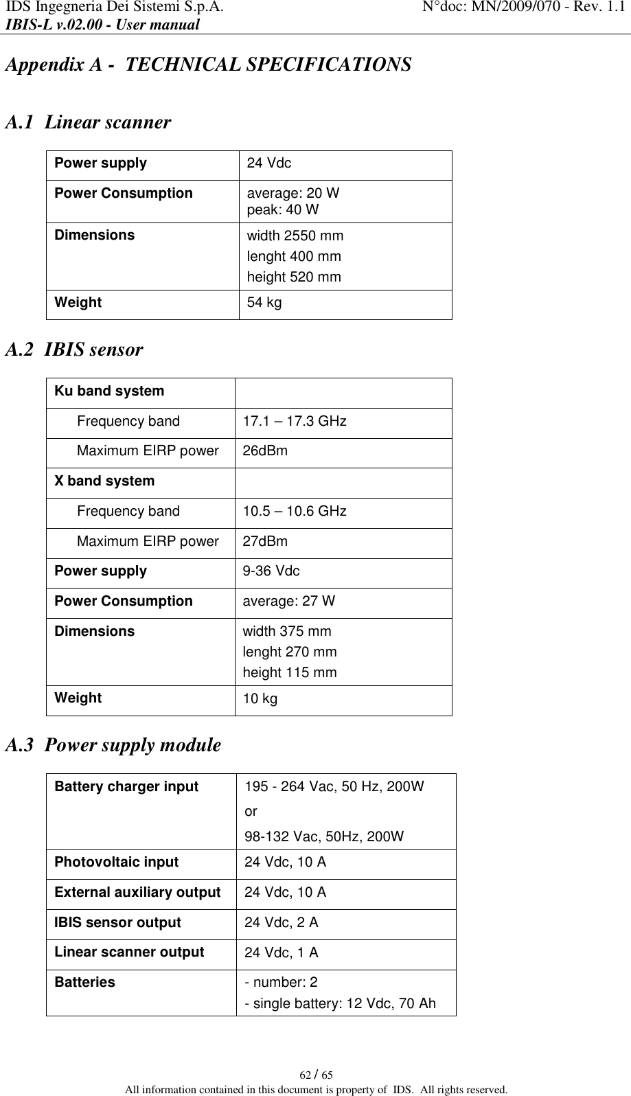
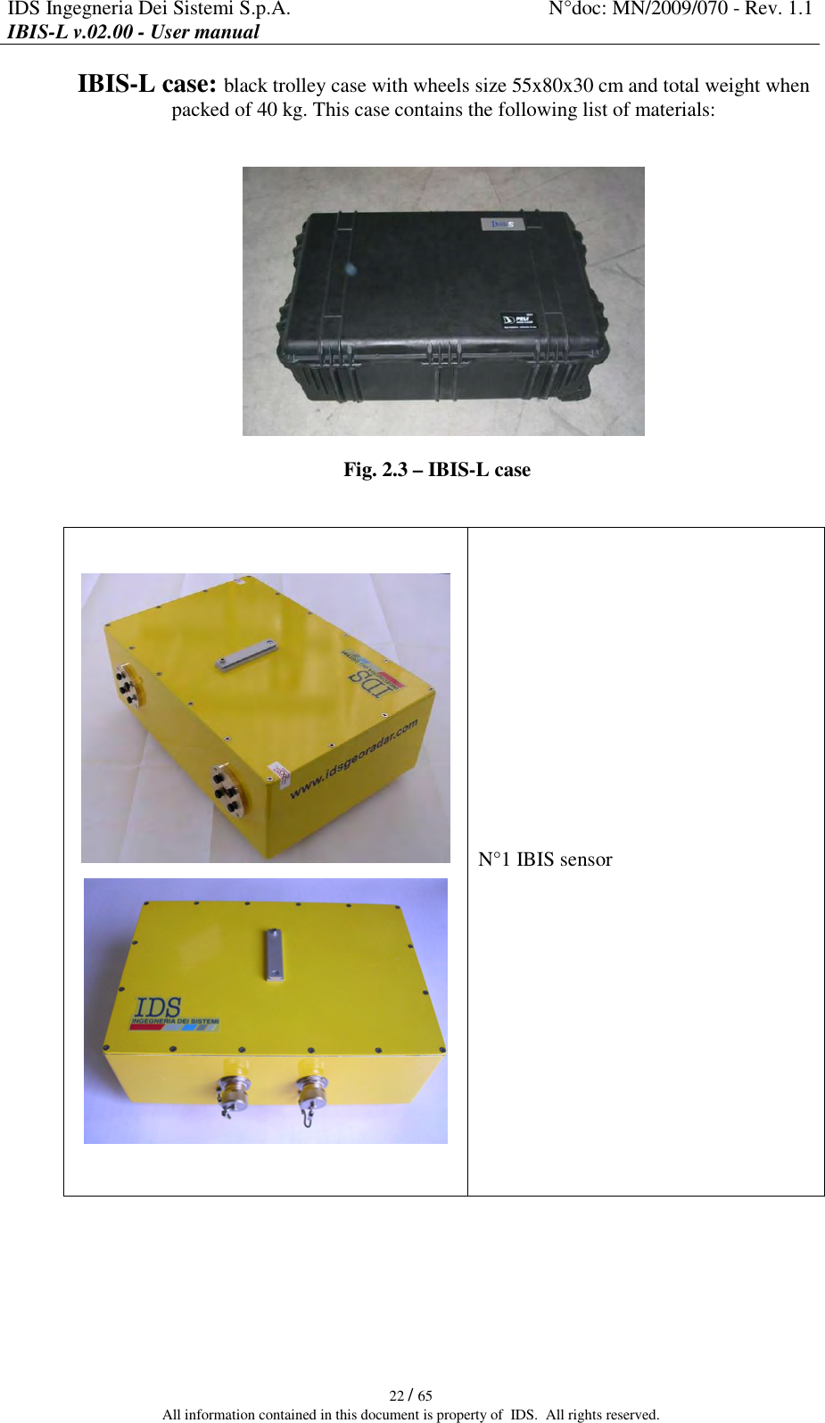
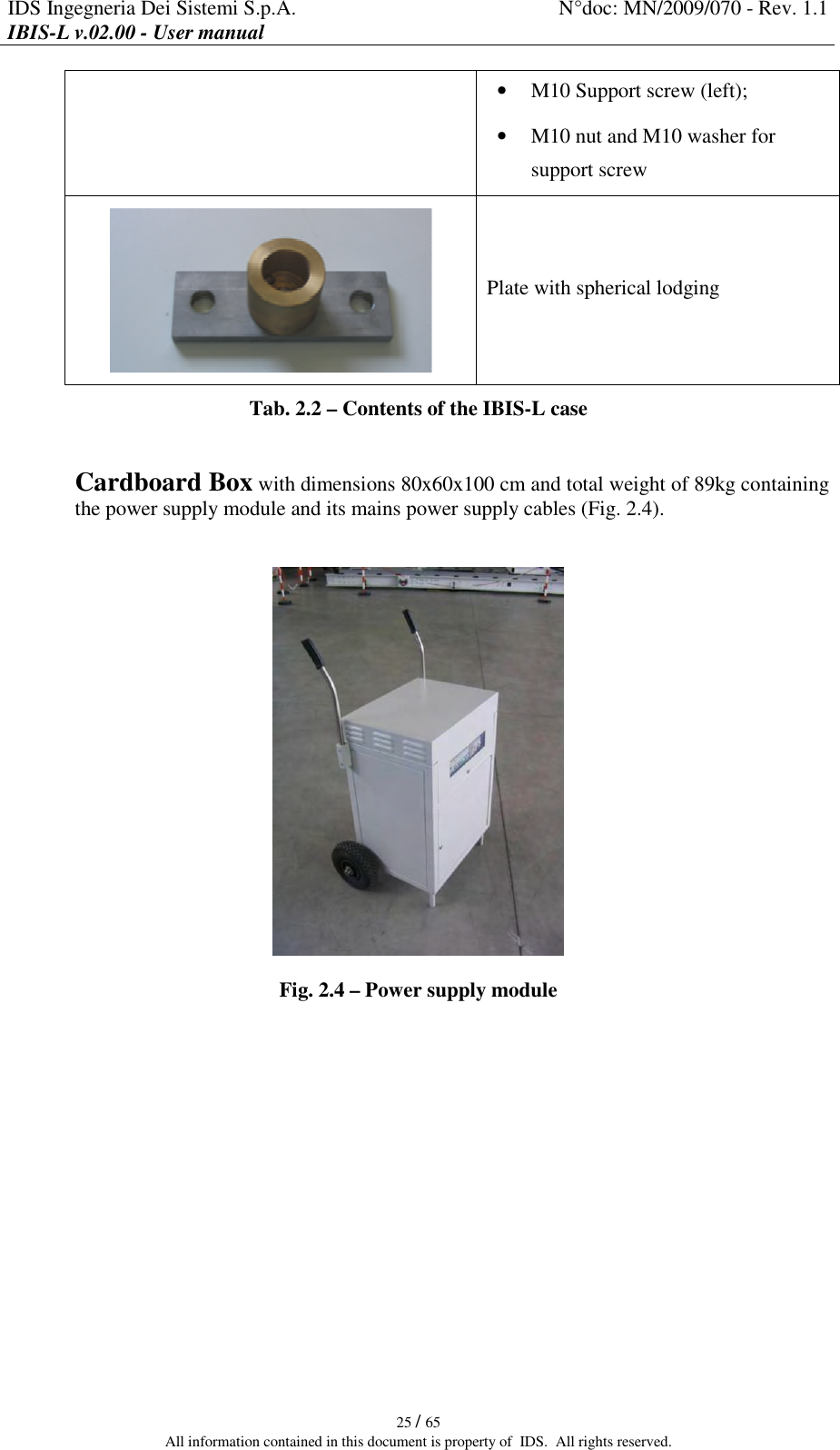
![IDS Ingegneria Dei Sistemi S.p.A. N°doc: MN/2009/070 - Rev. 1.1 IBIS-L v.02.00 - User manual 21 / 65 All information contained in this document is property of IDS. All rights reserved. 2.3 Pack contents IBIS-L box: wooden container with transportation handles, (size 2750x600x580 (width [cm] x length [cm] x height [cm]) and total weight when fully packed 107 kg). This box contains materials listed in Tab. 2.1. Fig. 2.2 – IBIS-L box Linear scanner Elevation pointing system Positioning template complete with 3 threaded bars with knobs and a spacer 3 DEM elements Tab. 2.1 – Contents of the IBIS-L box](https://usermanual.wiki/IDS-GeoRadar-s-r-l/IBIS-LS/User-Guide-1299773-Page-21.png)

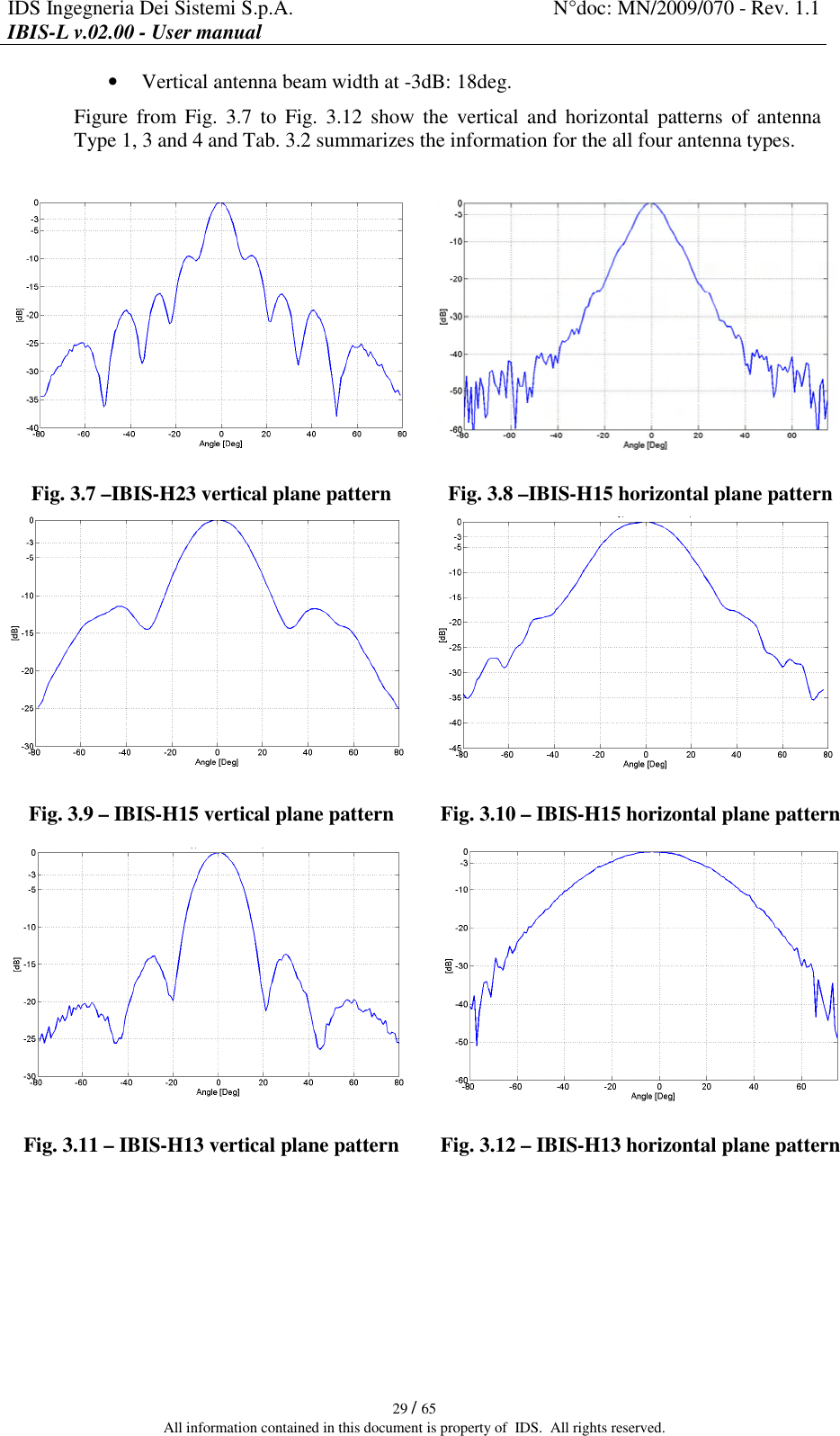
![IDS Ingegneria Dei Sistemi S.p.A. N°doc: MN/2009/070 - Rev. 1.1 IBIS-L v.02.00 - User manual 30 / 65 All information contained in this document is property of IDS. All rights reserved. Gain Elevation Azimuth Antenna Type [dBi] [deg] [deg] 1 - IBIS-H23 -3 dB azimuth beamwidth 10 11 -10 dB azimuth beamwidth 23,5 30 23 2 - IBISH20 -3 dB azimuth beamwidth 15 17 -10 dB azimuth beamwidth 20 45 34 3 - IBIS-H15 -3 dB azimuth beamwidth 25 29 -10 dB azimuth beamwidth 15 49 53 4 - IBISH13 -3 dB azimuth beamwidth 18 38 -10 dB azimuth beamwidth 13,5 30 70 Tab. 3.2 – Ku band Antennas characteristics 3.2.2 X band system antennas The X band IBIS-L system is provided with two identical antennas operating in vertical polarisation and characterised by a maximum gain of 21dBi. The amplitude characteristics of the antenna main lobe at -3 dB and -10 dB are provided in Tab. 3.3 and its vertical and horizontal patterns are shown in Fig. 3.13 and Fig. 3.14. For further details see appendix B.1 . X band antenna HORIZONTAL PLANE VERTICAL PLANE -3 dB 15° 15° -10 dB 27° 25° Tab. 3.3 – Width of the main lobes of the X band antennas at -3 dB and -10 dB Fig. 3.13 –X band antenna vertical plane pattern Fig. 3.14 – X band antenna horizontal plane pattern](https://usermanual.wiki/IDS-GeoRadar-s-r-l/IBIS-LS/User-Guide-1299773-Page-30.png)