IDS GeoRadar s r l IBIS-LS IBIS-L Linear Scanner User Manual MN 2009 070 11 manuale IBIS L PPR france FC cust
IDS Ingegneria dei Sistemi SpA IBIS-L Linear Scanner MN 2009 070 11 manuale IBIS L PPR france FC cust
User Manual
Tot pag. N°. = 65
- PRO/010/M1 Rev 4 -
INGEGNERIA DEI SISTEMI S.p.A.
Rev. 1.1
N°doc: MN/2009/070
Config.: IBIS-L -PRCS-OUT-MN
IBIS-L system
Image By Interferometric Survey - L
Pisa, June 2010
IBIS-L v.02.00 -
User manual

IDS Ingegneria Dei Sistemi S.p.A. N°doc: MN/2009/070 - Rev. 1.1
IBIS-L v.02.00 - User manual
2 / 65
All information contained in this document is property of IDS. All rights reserved.
KEY WORDS: IBIS-L, RADAR, INTERFEROMETER, INSTALLATION,
MAINTENANCE
SUMMARY: User and maintenance manual for the IBIS-L system. This document
illustrates the installation procedure for the linear scanner and IBIS-L
sensor and the acquisition start up procedure.
Document Evolution
Revision Date Reason for change
Rev. 1.0 October 2009 First Edition with Battery information according to DL 188
dated 20/11/2008
Rev. 1.1 June 2010 Document revision for Declarations for US and Canada
(see
RNC 201005097)
Document change record
RNC References Change description
201005097 Before index Declarations for US and Canadian customers
HW and SW versions covered by this document
IBIS-L system, IBIS-L Controller software v. 02.00.002.
Warning
IDS will not be held responsible for the consequences of an improper use of the equipment.
IDS will not be held responsible for the consequences of an improper use of the software.
All information contained in this document is property of IDS
Contacts
IDS Ingegneria Dei Sistemi S.p.A.
Via Sterpulino, 20
56121 PISA (Loc. Ospedaletto)
Tel: +3905096711
Fax: +39050961721

IDS Ingegneria Dei Sistemi S.p.A. N°doc: MN/2009/070 - Rev. 1.1
IBIS-L v.02.00 - User manual
3 / 65
All information contained in this document is property of IDS. All rights reserved.
DISCLAIMER
IDS WILL NOT BE HELD RESPONSIBLE FOR THE
CONSEQUENCES
OF AN IMPROPER USE OF THE EQUIPMENT AND/
OR THE
SOFTWARE.
THIS SOFTWARE MAY INCLUDE AUTOMATED DATA
PROCESSING AND ANALYSIS TOOLS.
WHILE EVERY EFFORT IS MADE TO ENSURE THE AC
CURACY OF
THE INFORMATION PROVIDED BY THOSE TOOLS,
THEY MUST
NOT BE INTENDED AS A SUBSTITUTE FOR INTE
LLIGENT
ANALYSIS; RATHER, THEY HAVE TO BE INTEND
ED AS AN
ADVISOR AND THE USER MUST NOT COMPLETELY
RELY ON THE
RESULTS PROVIDED BY THEM TO GIVE THE COMPLETE
ANSWER.
IDS INGEGNERIA DEI SISTEMI SPA ASSUMES NO LIABILITY FOR
ANY DIRECT, INDIRECT, SPECIAL, INCIDENTAL OR
CONSEQUENTIAL DAMAGES OR INJURIES CAUSED BY SUCH
RELIANCE ON THE ACCURACY, RELIABILITY, OR TIMELESS OF
THE INFORMATION PROVIDED BY THOSE TOOLS.
ANY PERSON OR ENTITY WHO RELIES ON INFORMATION
OBTAINED FROM THE AUTOMATED DATA
PROCESSING/ANALYSIS TOOLS ONLY
, DOES SO AT HIS OR HER
OWN RISK.
IDS Ingegneria Dei Sistemi S.p.A. N°doc: MN/2009/070 - Rev. 1.1
IBIS-L v.02.00 - User manual
4 / 65
All information contained in this document is property of IDS. All rights reserved.
SAFETY INFORMATION

IDS Ingegneria Dei Sistemi S.p.A. N°doc: MN/2009/070 - Rev. 1.1
IBIS-L v.02.00 - User manual
5 / 65
All information contained in this document is property of IDS. All rights reserved.
Warning: this equipment is destined for use in industrial
environments
(Class A apparatus). In residential, commercial and light industry
environments, this apparatus may generate radio interference: in this case,
the user may be required to operate while taking appropriate
countermeasures.
The apparatus is sensi
tive to the presence of external electromagnetic fields,
which may reduce its performance.

IDS Ingegneria Dei Sistemi S.p.A. N°doc: MN/2009/070 - Rev. 1.1
IBIS-L v.02.00 - User manual
6 / 65
All information contained in this document is property of IDS. All rights reserved.
IMPORTANT NOTE FOR THE US CUSTOMERS
Model No.: IBIS-KU
FCC ID: UFW-IBIS-KU
This device complies with part 90 of the FCC Rules.
Caution: Any changes or modifications to this device not explicitly approved by manufacturer could void your
authority to operate this equipment.
This equipment complies with FCC radiation exposure limits set forth for an uncontrolled environment. This
equipment should be installed and operated with minimum 20 cm between the radiator and your body. This
transmitter must not be collocated or operating in conjunction with any other antenna or transmitter unless
authorized to do so by the FCC.
Model No.: IBIS-SU-STD , IBIS-SU-ADV
FCC ID: UFW-IBIS-SU-M
This device complies with part 15 of the FCC Rules. Operation is subject to the following two conditions: (1) This
device may not cause harmful interference, and (2) this device must accept any interference received, including
interference that may cause undesired operation.
Caution: Any changes or modifications to this device not explicitly approved by manufacturer could void your
authority to operate this equipment.
Model No.: IBIS-LS
FCC ID: UFW-IBIS-LS
This device complies with part 15 of the FCC Rules. Operation is subject to the following two conditions: (1) This
device may not cause harmful interference, and (2) this device must accept any interference received, including
interference that may cause undesired operation.
Caution: Any changes or modifications to this device not explicitly approved by manufacturer could void your
authority to operate this equipment.

IDS Ingegneria Dei Sistemi S.p.A. N°doc: MN/2009/070 - Rev. 1.1
IBIS-L v.02.00 - User manual
7 / 65
All information contained in this document is property of IDS. All rights reserved.
IMPORTANT NOTE FOR THE CANADIAN CUSTOMERS
Model No.: IBIS-KU
IC ID: 8991A-IBISKU
This device has been designed to operate with the antennas listed below, and having a maximum gain of 22 dB.
Antennas not included in this list or having a gain greater than 22 dB are strictly prohibited for use with this device.
The required antenna impedance is 50 ohms.
IBIS-ANT1-H38V18
IBIS-ANT2-H29V25
IBIS-ANT3-H17V15
IBIS-ANT4-H11V10
IBIS-ANT5-H12V39
IBIS-ANT6-H51V20
Operation is subject to the following two conditions: (1) this device may not cause interference, and (2) this device
must accept any interference, including interference that may cause undesired operation of the device.
To reduce potential radio interference to other users, the antenna type and its gain should be so chosen that the
equivalent isotropically radiated power (e.i.r.p.) is not more than that permitted for successful communication.

IDS Ingegneria Dei Sistemi S.p.A. N°doc: MN/2009/070 - Rev. 1.1
IBIS-L v.02.00 - User manual
8 / 65
All information contained in this document is property of IDS. All rights reserved.
!
WARNING
CLEANING INFORMATION
Before cleaning any external parts of the apparatus, make sure
that all cables have been disconnected, including the power
supply cable. If a damp cloth is used, make
sure it is not too wet,
to avoid any damage to the electrical components of the
equipment. Wait until the equipment is totally dry before
reconnecting the cables.
The IBIS-L should be cleaned periodically using a damp cloth.
Do not use solvents or abrasive detergents.
Do not apply liquid directly to the electrical contacts of the
various connectors.
If a specific spray is used to clean the PC
TFT monitor, make sure it is not flammable; i
n any case, do not
spray it directly on the screen, instead, spray it o
nto the cleaning
cloth.
IDS Ingegneria Dei Sistemi S.p.A. N°doc: MN/2009/070 - Rev. 1.1
IBIS-L v.02.00 - User manual
9 / 65
All information contained in this document is property of IDS. All rights reserved.
BATTERIES REMOVAL INFORMATION
Laptop Batteries:
Manufacturer: PANASONIC
Type: Li-ion Ni
Characteristics: 10.65V 5.7Ah
Removal instructions:
1. turn off the laptop;
2. open the drawer marked with the battery symbol;
3. extract the battery pack by pulling the tab.
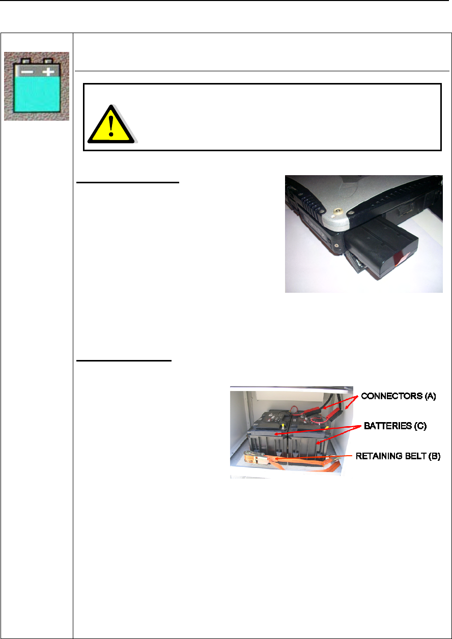
Radar batteries:
Manufacturer:
ENERSYS GENESIS
EP
Type: rechargeable lead
acid, non spillable
batteries
Characteristics: 12V & 70Ah
Removal instructions:
1. open the front door of the power supply module;
2. disconnect the connectors (A);
3. open the retaining belt (B);
4. extract the batteries (C).
NOTE
: Batteries must be recycled according to national regulations. Read
carefully the warnings and information on the batteries.

IDS Ingegneria Dei Sistemi S.p.A. N°doc: MN/2009/070 - Rev. 1.1
IBIS-L v.02.00 - User manual
10 / 65
All information contained in this document is property of IDS. All rights reserved.
RECICLYING
The crossed out wheeled bin symbol shown on the equipment indicates that
the product must be recycled separately from other waste at the end of its
useful life.
Separate waste disposal of this product at the end of its useful life will be
organised and managed by IDS. When you decide to dispose of the
equipment, contact IDS and follow the system that IDS has set up to permit
the separate collection of the apparatus at its life end.
Adequate separate collection for its subsequent recycling, treatment and
environmental friendly disposal contribute towards avoiding any
unnecessary effects on the environment and to health and favour the reuse or
recycling of the materials that make up the equipment. Unauthorised disposal
of this product as unsorted waste by its possessor will lead to an
administrative penalty foreseen by national regulations.

IDS Ingegneria Dei Sistemi S.p.A. N°doc: MN/2009/070 - Rev. 1.1
IBIS-L v.02.00 - User manual
11 / 65
All information contained in this document is property of IDS. All rights reserved.
WARRANTY CERTIFICATE CONDITIONS
1) IDS Ingegneria dei Sistemi S.p.A, hereinafter referred to as IDS, warrants hardware/software
products for a period of 12 months from the delivery date to the original customer;
2) The delivery date is certified by the “Warranty Registration Form”;
3) IDS’s hardware products will be free from defects in materials workmanship under normal use and
service;
4) IDS’s obligation is limited to repairing or replacing parts or equipment which are returned to IDS,
without alteration or further damage, and which in IDS s judgment, were defective or became
defective during normal use;
5) IDS’ software will have to be installed on a PC according to the requirement of the IDS hardware (
see IDS User’s Guide the Software Data Acquisition);
6) IDS’ s software products designed by IDS for use for IDS hardware products are warranted not to
fail to execute their programming instructions due to defects during the warranty period, provided
they are properly installed on IDS hardware products. IDS does not warrant if the IDS software will
be used and operated in hardware and software combinations not selected by IDS;
7) IDS does not assumes any liability for any direct, indirect, special, incidental or consequential
damages or injuries caused by proper or improper operation of its equipment whether defective or
not defective;
8) This software may include automated data processing and analysis tools. While every effort is made
to ensure the accuracy of the information provided by those tools, they must not be intended as a
substitute for intelligent analysis; rather, they have to be intended as an advisor and the user must
not completely rely on the results provided by them to give the complete answer. IDS assumes no
liability for any direct, indirect special, incidental or consequential damages or injuries caused by
such reliance on the accuracy, reliability, or timeliness of the information provided by those tools.
Any person or entity who relies on information obtained from the automated data
processing/analysis tools only, does so at his or her own risk;
9) IDS’s warranty does not extend and shall not apply to:
a) Products which have been repaired or altered by other than IDS personnel;
b) Products which have been subjected to misuse, neglect, accident or improper installation;
c) Products in which have been installed Hardware/Software accessories not supplied by IDS
and/or without any approval by IDS;
d) Products which have been connected to equipment different from the ones supplied by IDS
(except the PC data Logger which must conform to IDS specifications;
e) Products which have been damaged by natural disaster or calamities.
10) Before returning any equipment to IDS , you have to contact the IDS Customer Care Office that will
authorize you to return the material to be repaired;
11) Once the parts/equipment to be repaired arrive to IDS, IDS may inspect the defective products to
verify they are eligible for repair or replacement. All packing must be saved for inspection purpose
in order to assist IDS to understand the cause of the defects. IDS, will not be obliged to repair, or
replace for products returned as defective but damaged from abuse, misuse, negligence , accident
loss or damage in transit;
12) The final clients, is responsible for ensuring the defective products returned to be properly
packaged;
13) The above warranty are sole and exclusive, and no other warranty, whether written or oral, is
expressed or implied.

IDS Ingegneria Dei Sistemi S.p.A. N°doc: MN/2009/070 - Rev. 1.1
IBIS-L v.02.00 - User manual
12 / 65
All information contained in this document is property of IDS. All rights reserved.
INDEX
1. Introduction........................................................................................................................... 16
1.1 Aim................................................................................................................................. 16
1.2 Field of application........................................................................................................ 16
1.3 Authorisation for use – national restriction .................................................................. 16
1.4 CE Marking ................................................................................................................... 17
1.5 Acronyms and Definitions.............................................................................................. 17
1.5.1 Acronyms.......................................................................................................................17
1.5.2 Definitions......................................................................................................................17
2. Overview................................................................................................................................. 18
2.1 How to use this manual.................................................................................................. 18
2.2 General description....................................................................................................... 18
2.3 Pack contents................................................................................................................. 21
3. IBIS-L system hardware configuration............................................................................... 26
3.1 IBIS sensor..................................................................................................................... 26
3.2 Antennas ........................................................................................................................ 27
3.2.1 Ku band system antennas...............................................................................................27
3.2.2 X band system antennas.................................................................................................30
3.3 Linear Scanner............................................................................................................... 31
3.4 Installation kit................................................................................................................ 34
3.5 Power supply module..................................................................................................... 35
3.6 Control and acquisition PC........................................................................................... 39
3.7 Connection cable kit ...................................................................................................... 40
4. IBIS-L system installation procedure.................................................................................. 42
4.1 Installation of the linear scanner................................................................................... 42
4.1.1 Material required............................................................................................................42
4.1.2 Preparing the anchor points for the linear scanner .........................................................47
4.1.3 Mounting the linear scanner...........................................................................................49
4.2 Installation of the IBIS sensor and module connection................................................. 52
4.3 Dismantling the measurement site................................................................................. 56
5. First start up .......................................................................................................................... 57
6. Useful Tips.............................................................................................................................. 59
6.1 Installation..................................................................................................................... 59
6.2 Use................................................................................................................................. 60
6.3 Dismantling ................................................................................................................... 60
7. Maintenance........................................................................................................................... 61

IDS Ingegneria Dei Sistemi S.p.A. N°doc: MN/2009/070 - Rev. 1.1
IBIS-L v.02.00 - User manual
13 / 65
All information contained in this document is property of IDS. All rights reserved.
7.1 Maintenance of the module base ................................................................................... 61
7.2 Maintenance of the movement system............................................................................ 61
7.3 General maintenance of the module.............................................................................. 61
Appendix A - Technical specifications..................................................................................... 62
A.1 Linear scanner............................................................................................................... 62
A.2 IBIS sensor .................................................................................................................... 62
A.3 Power supply module .................................................................................................... 62
A.4 Panasonic CF-19 Notebook PC.................................................................................... 63
Appendix B - Elements of radar technology........................................................................... 64
B.1 Antenna beam................................................................................................................ 64
FIGURES INDEX
FIG. 2.1 – INSTRUMENT INSTALLED AT THE CHIES D’ALPAGO TO MONITOR THE TESSINA
VALLEY LANDSLIDE (BL).............................................................................................................20
FIG. 2.2 – IBIS-L BOX ................................................................................................................................21
FIG. 2.3 – IBIS-L CASE ..............................................................................................................................22
FIG. 2.4 – POWER SUPPLY MODULE .....................................................................................................25
FIG. 3.1 – IBIS SENSOR.............................................................................................................................26
FIG. 3.2 – BACK (A) AND FRONT (B) VIEW OF THE SENSOR...........................................................27
FIG. 3.3 – BOTTOM VIEW OF SENSOR ..................................................................................................27
FIG. 3.4 – IBIS-H20 VERTICAL PLANE PATTERN................................................................................28
FIG. 3.5 – IBIS-H20 HORIZONTAL PLANE PATTERN..........................................................................28
FIG. 3.6 – IBIS-H20 ANTENNA.................................................................................................................28
FIG. 3.7 –IBIS-H23 VERTICAL PLANE PATTERN.................................................................................29
FIG. 3.8 –IBIS-H15 HORIZONTAL PLANE PATTERN...........................................................................29
FIG. 3.9 – IBIS-H15 VERTICAL PLANE PATTERN................................................................................29
FIG. 3.10 – IBIS-H15 HORIZONTAL PLANE PATTERN........................................................................29
FIG. 3.11 – IBIS-H13 VERTICAL PLANE PATTERN..............................................................................29
FIG. 3.12 – IBIS-H13 HORIZONTAL PLANE PATTERN........................................................................29
FIG. 3.13 –X BAND ANTENNA VERTICAL PLANE PATTERN ...........................................................30
FIG. 3.14 – X BAND ANTENNA HORIZONTAL PLANE PATTERN ....................................................30
FIG. 3.15 – INSTALLED LINEAR SCANNER..........................................................................................31
FIG. 3.16 – BACK OF LINEAR SCANNER...............................................................................................32
FIG. 3.17 – FRONTAL VIEW OF THE SYSTEM FOR FIXING THE LINEAR SCANNER WITH
DETAILS OF (A) THE POSITIONING FORK, (B) HOUSING OF THE SPHERE WITH THE
SPHERE INSERTED AND (C) THE TWO SUPPORT STUDS.......................................................33
FIG. 3.18 – VIEW OF THE DRILLING AND POSITIONING TEMPLATE WITH SPACER .................34
FIG. 3.19 – ELEMENTS FOR ANCHORING THE LINEAR SCANNER.................................................34

IDS Ingegneria Dei Sistemi S.p.A. N°doc: MN/2009/070 - Rev. 1.1
IBIS-L v.02.00 - User manual
14 / 65
All information contained in this document is property of IDS. All rights reserved.
FIG. 3.20 – FRONT (LEFT) AND BACK (RIGHT) VIEW OF THE POWER SUPPLY MODULE. NOTE
THE HANDLES, TWO WHEELS AND THREE LOCKABLE DOORS .........................................35
FIG. 3.21 - SEQUENCE FOR UNFOLDING THE POWER SUPPLY UNIT HANDLES.........................36
FIG. 3.22 –THE NOTEBOOK PC TABLE..................................................................................................36
FIG. 3.23 - THE POWER SUPPLY MODULE SWITCHBOARD.............................................................37
FIG. 3.24 - (A) BATTERY HOUSING AREA, (B) POWER SUPPLY MODULE CONNECTOR AREA
WITH THE GROUND SCREW HIGHLIGHTED.............................................................................38
FIG. 3.25 – PANASONIC CF-19 PC ...........................................................................................................40
FIG. 3.26 – SCHEMATIC DIAGRAM OF CONNECTIONS.....................................................................41
FIG. 4.1 - OPENED IBIS-L BOX ................................................................................................................43
FIG. 4.2 – WING NUTS FIXING THE LINEAR SCANNER ....................................................................43
FIG. 4.3 – (A) POINTING SYSTEM, (B) DEM SPACERS (C) TEMPLATE SPACER............................44
FIG. 4.4 – SEQUENCE FOR REMOVING THE ELEVATION POINTING SYSTEM ............................44
FIG. 4.5 – IBIS-L CASE ..............................................................................................................................45
FIG. 4.6 – IBIS-L CASE - INTERNAL VIEW............................................................................................46
FIG. 4.7 – IBIS-L CASE - INTERNAL VIEW............................................................................................46
FIG. 4.8 – VIEW OF THE TEMPLATE PLACED ON THE BASE...........................................................47
FIG. 4.9 – MOUNTING THE STUDS ON THE TEMPLATE, DETAIL OF THE CENTRAL PLATE
WITH THE SPACER AND ITS TWO STUDS .................................................................................48
FIG. 4.10 – RESIN INJECTION OPERATION...........................................................................................48
FIG. 4.11 – MOUNTING THE BASE WASHERS .....................................................................................49
FIG. 4.12 – THE CORRECTLY INSTALLED POSITIONING FORK......................................................50
FIG. 4.13 – SEQUENCE FOR MOUNTING THE SPHERICAL THRUST BEARINGS ..........................50
FIG. 4.14 – MOUNTING THE FIXING PLATE TO THE SPHERICAL HOUSING ................................50
FIG. 4.15 – CONTACT BETWEEN THE SPHERICAL HOUSING AND THE SPHERE. LEFT SHOWS
THE CORRECT POSITION, CENTRE SHOWS THE SPHERE POSITION TOO HIGH, RIGHT
SHOWS THE SPHERE TOUCHING THE BOTTOM OF THE HOUSING ....................................51
FIG. 4.16 – STEPS 16 TO 18.......................................................................................................................52
FIG. 4.17 - POSITIONING THE ELEVATION POINTING SYSTEM ONTO THE LINEAR SCANNER53
FIG. 4.18 – CORRECTLY INSTALLED ELEVATION POINTING SYSTEM (A) WITHOUT AND (B)
WITH THE DEM SPACERS .............................................................................................................53
FIG. 4.19 - LEFT AND CENTRE: DETAIL OF THE IBIS SENSOR CONNECTOR. RIGHT: TWO
PROTECTIVE CAPS FOR THE CONNECTORS.............................................................................54
FIG. 4.20 – CONNECTIONS BETWEEN IBIS SENSOR - LINEAR SCANNER –POWER SUPPLY
MODULE -PC ....................................................................................................................................55
FIG. 4.21 – FULLY INSTALLED IBIS-L SYSTEM ..................................................................................55
FIG. 5.1 - OPENING WINDOW OF THE CONTROL AND ACQUISITION SOFTWARE.....................57
FIG. 5.2 – THE CONFIGURATION PANEL..............................................................................................58
FIG. B. 1 – SCHEMATIC DIAGRAM OF THE ANTENNA BEAM.........................................................64
FIG. B. 2 – AREA OF THE SCENARIO COVERED BY THE ANTENNA BEAM MAIN LOBE. .........65

IDS Ingegneria Dei Sistemi S.p.A. N°doc: MN/2009/070 - Rev. 1.1
IBIS-L v.02.00 - User manual
15 / 65
All information contained in this document is property of IDS. All rights reserved.
TABLES INDEX
TAB. 2.1 – CONTENTS OF THE IBIS-L BOX ..........................................................................................21
TAB. 2.2 – CONTENTS OF THE IBIS-L CASE ........................................................................................25
TAB. 3.1 – WIDTH OF THE MAIN LOBES OF THE IBIS-H20 ANTENNAS AT -3 DB AND -10 DB.27
TAB. 3.2 – KU BAND ANTENNAS CHARACTERISTICS......................................................................30
TAB. 3.3 – WIDTH OF THE MAIN LOBES OF THE X BAND ANTENNAS AT -3 DB AND -10 DB .30
TAB. 3.4 – PROCEDURE FOR SETTING THE VOLTAGE.....................................................................39
TAB. 7.1 – SUMMARY TABLE OF ORDINARY MAINTENANCE ACTIONS.....................................61

IDS Ingegneria Dei Sistemi S.p.A. N°doc: MN/2009/070 - Rev. 1.1
IBIS-L v.02.00 - User manual
16 / 65
All information contained in this document is property of IDS. All rights reserved.
1. INTRODUCTION
This document describes the IBIS-L system (Image By Interferometric Survey -L), with
particular reference to the concepts the user should learn before starting to use this device.
Therefore we recommend to read the entire document before starting up the system.
If technical assistance is required, please use the contact numbers provided on page 3 of
this manual.
1.1 Aim
Reading this document will provide the operator with all the necessary knowledge to
install and maintain the IBIS-L system. In particular, it provides a step by step procedure
for installation of the system, information for the safe use of the system and instructions
for general maintenance.
1.2 Field of application
This document applies to the installation of the IBIS system in -L configuration and its
use in the field for monitoring of quasi static phenomena.
1.3 Authorisation for use – national restriction
European countries
IBIS-L system has been classified from the CEPT Administrations as SRD – Short Range
Device - i.e. a device that doesn’t cause interference to other systems operating in the
same frequency band. IBIS-L has so been included (as Ground Based SAR) in the
ERC/REC 70-03 that defines the SRD equipment.
For Ku band system
In the meanwhile that all the European countries update their national frequency
allocation table applying the new recommendation, currently the use of IBIS-L system
outside a laboratory can be still subject to authorisation by the Competent Ministry of the
country where the system should be used. Please refer to the Competent Ministry of the
country where the system should be used to know whether there is still the need of an
authorisation or not.
For X band system
Almost all the European countries have applied the ERC/REC 70-03 for the X band
system. Please refer to the Competent Ministry of the country where the system should be
used to know if there are some limitations in the use of X band IBIS-L equipment or not.

IDS Ingegneria Dei Sistemi S.p.A. N°doc: MN/2009/070 - Rev. 1.1
IBIS-L v.02.00 - User manual
17 / 65
All information contained in this document is property of IDS. All rights reserved.
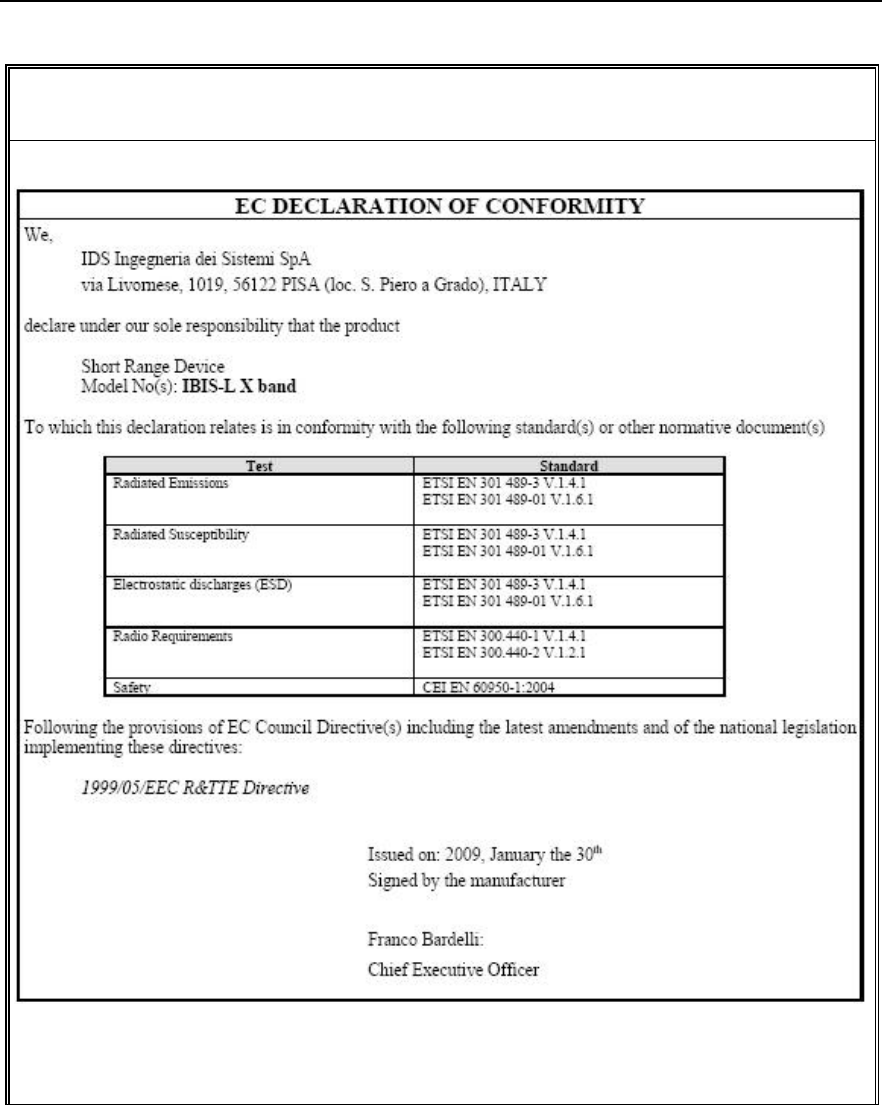
1.4 CE Marking
This equipment is in compliance with the essential requirements and
other relevant provisions of Directive 1999/5/EC.
The full Declaration of Conformity can be found either on the CD or
a separate document included with this product.
This is a Class A product. In a domestic environment it may cause
radio interference, in which case the user may be required to take
adequate measures.
1.5 Acronyms and Definitions
1.5.1 Acronyms
DEM Digital Elevation Model
IBIS Image By Interferometric Survey
SAR Synthetic Aperture Radar
SF-CW Stepped Frequencies - Continuous Wave
1.5.2 Definitions
Range Bin area of resolution in distance used in the IBIS-S system.
Pixel area of resolution used in the IBIS-L system.
Radial displacement displacement of the range bin or the pixel along the direction
joining the Range bin or pixel to the IBIS system i.e. along the
LOS – Line of Sight.

IDS Ingegneria Dei Sistemi S.p.A. N°doc: MN/2009/070 - Rev. 1.1
IBIS-L v.02.00 - User manual
18 / 65
All information contained in this document is property of IDS. All rights reserved.
2. OVERVIEW
This manual describes the operations that the user must perform to set up and use the
IBIS-L system.
2.1 How to use this manual
This manual consists of the following chapters:
• Chapter 1 - Introduction
• Chapter 2 - Overview
• Chapter 3 - IBIS-L system hardware configuration
• Chapter 4 - IBIS-L system installation procedure
• Chapter 5 - First start up
• Chapter 6 - Useful Tips
• Chapter 7 - Maintenance
• Appendix A - Technical specifications
• Appendix B - Elements of radar technology
2.2 General description
The IBIS-L system is designed to remotely measure slow displacements with an accuracy
as great as a tenth of a millimetre. The IBIS-L system is particularly suitable for terrain
and structural monitoring applications, with the aim of detecting quasi-static
displacements over long time periods.
The performance of the IBIS-L system depends on the type of configuration used and on
the operative measurement conditions (above all related to the reflectivity of the area
under investigation); however, the best performance characteristics can be defined as
follows:
For Ku band system:
Maximum operational distance: 4000m;
Image resolution in distance: 0.75m;
Angular resolution: 4.3mrad;
Accuracy in measuring displacements in the viewing direction: 0.1 mm (for
points with a good reflectivity - SNR>50dB – and depending on the impact of
atmospheric variation on the measure).
For X band system:
Maximum operational distance: 4000m;
Image resolution in distance: 1.5m;
Angular resolution: 7.1mrad.
Accuracy in measuring displacements in the viewing direction: 0.1 mm (for
points with a good reflectivity - SNR>50dB – and depending on the impact of
atmospheric variation on the measure).

IDS Ingegneria Dei Sistemi S.p.A. N°doc: MN/2009/070 - Rev. 1.1
IBIS-L v.02.00 - User manual
19 / 65
All information contained in this document is property of IDS. All rights reserved.
The time required for instrument installation is about 2h.
The instrument has been specifically conceived for outdoor use and is equipped with an
installation system designed to guarantee high precision when repositioning it at a later
date. This is important to enable measurements to be performed over time without
needing to leave the instrument on-site.
The IBIS-L system offers the following advantages over currently available monitoring
systems (GPS, extensometers):
Permits the operator to perform remote monitoring of the area (remote sensing),
without the need to access the area to install sensors or optical targets;
Supplies a continuous displacement map of the entire area. The IBIS-L system
simultaneously measures all the displacements of the entire area illuminated by
the antenna beam, which can cover as much as hundreds of thousands of square
meters;
Directly measure the displacements of the territory of interest in near real time;
It can be used both day and night and in almost all weather conditions;
It doesn’t require the continuous presence of an operator and can be controlled by
wireless connection.
This possibility of also performing long distance monitoring, with no need to install
sensors means that investigations can be performed even when:
the area of interest is not accessible;
the area of interest is particularly large and therefore would require many in situ
sensors;
In addition, when the monitoring activity is required to assure people’s safety in
emergency situations, the possibility of performing remote monitoring may be essential
for protecting lives.
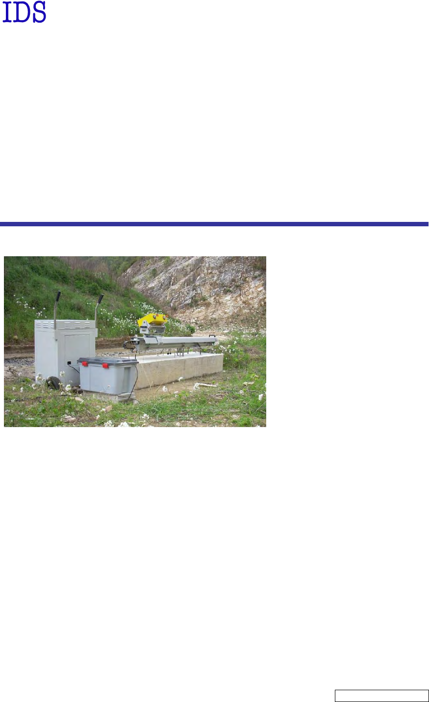
Fig. 2.1 shows the composition of IBIS-L system. The main components are:
o Sensor module: this generates, transmits and receives the electromagnetic signal.
The sensor module is installed on the linear scanner: movement of the sensor on
the linear scanner permits the use of the SAR technique to obtain a two
dimensional image of the scenario. This module has a USB interface for
connection with the control PC and an interface to the positioning module;
o Linear Scanner, consisting of a 2.5 metre long aluminium track, along which a
slide is moved under the control of a step by step motor;
o The control PC, installed with the system management software. This is used to
configure the acquisition parameters, manage measurements and view the results
in real time;
o Power supply: this supplies power to the system through a battery unit or
connection to an external energy supply.
A detailed description of each component is reported in paragraph 3.
IDS Ingegneria Dei Sistemi S.p.A. N°doc: MN/2009/070 - Rev. 1.1
IBIS-L v.02.00 - User manual
20 / 65
All information contained in this document is property of IDS. All rights reserved.
Fig. 2.1 – Instrument installed at the Chies d’Alpago to monitor the Tessina valley landslide
(BL)
Power supply module
IBIS
-
L
sensor
Linear Scanner
Control & acquisition
notebook
IDS Ingegneria Dei Sistemi S.p.A. N°doc: MN/2009/070 - Rev. 1.1
IBIS-L v.02.00 - User manual
21 / 65
All information contained in this document is property of IDS. All rights reserved.
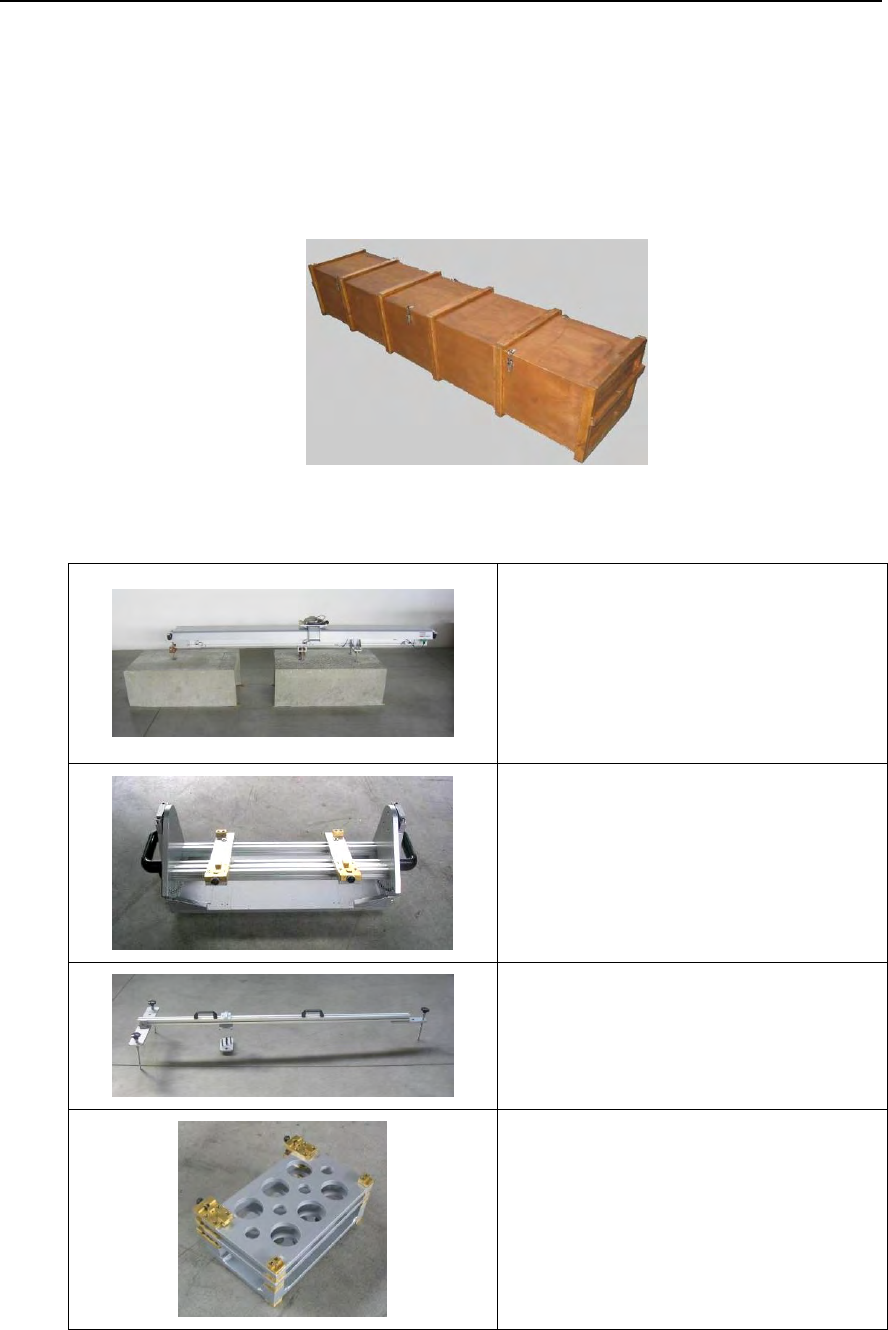
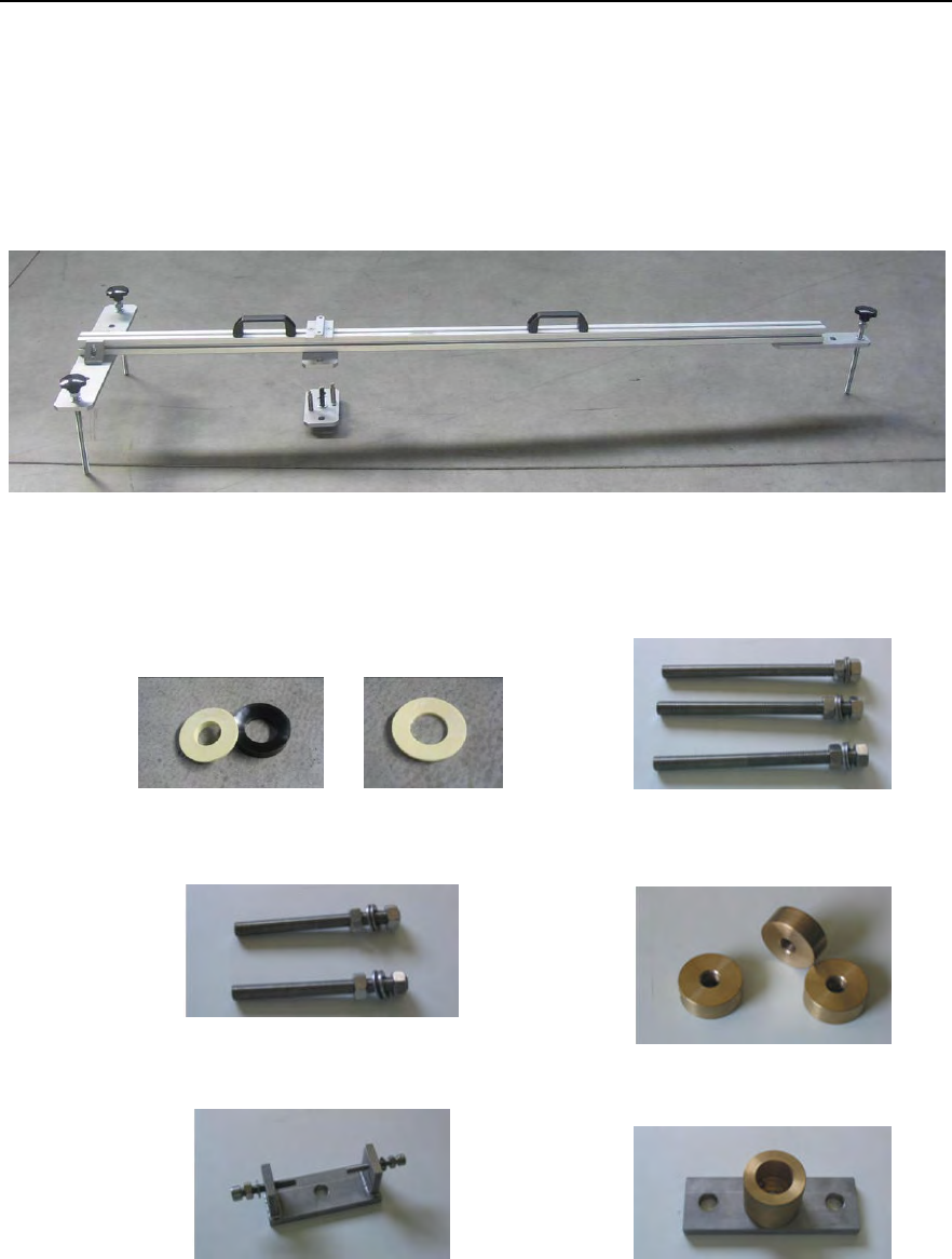
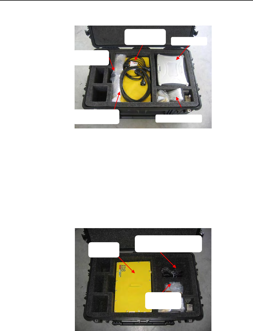
2.3 Pack contents
IBIS-L box: wooden container with transportation handles, (size 2750x600x580
(width [cm] x length [cm] x height [cm]) and total weight when fully
packed 107 kg). This box contains materials listed in Tab. 2.1.
Fig. 2.2 – IBIS-L box
Linear scanner
Elevation pointing system
Positioning template complete with 3
threaded bars with knobs and a spacer
3 DEM elements
Tab. 2.1 – Contents of the IBIS-L box
IDS Ingegneria Dei Sistemi S.p.A. N°doc: MN/2009/070 - Rev. 1.1
IBIS-L v.02.00 - User manual
22 / 65
All information contained in this document is property of IDS. All rights reserved.
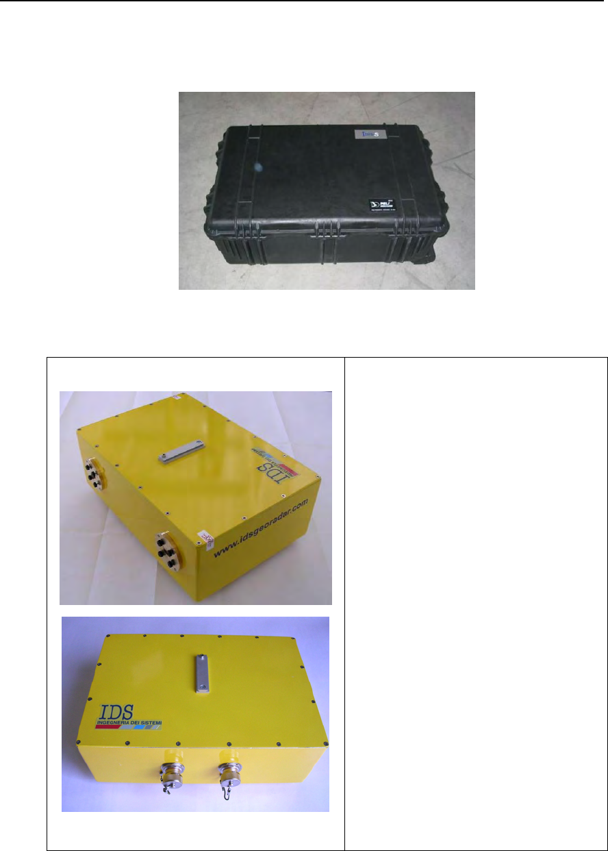
IBIS-L case: black trolley case with wheels size 55x80x30 cm and total weight when
packed of 40 kg. This case contains the following list of materials:
Fig. 2.3 – IBIS-L case
N°1 IBIS sensor
IDS Ingegneria Dei Sistemi S.p.A. N°doc: MN/2009/070 - Rev. 1.1
IBIS-L v.02.00 - User manual
23 / 65
All information contained in this document is property of IDS. All rights reserved.
Optical telescope
A pair of antennas, each with 4 fixing
screws.
1 Panasonic CF19 PC (the original PC
packaging complete with guarantees and
software licenses is provided separately)
1 mains power supply cable for the PC
1 USB cable to connect the IBIS-L
sensor to the power supply module (3m)
IDS Ingegneria Dei Sistemi S.p.A. N°doc: MN/2009/070 - Rev. 1.1
IBIS-L v.02.00 - User manual
24 / 65
All information contained in this document is property of IDS. All rights reserved.
1 power supply cable to connect the
power supply module to the IBIS-L
sensor (3m)
1 IBIS-L Manual;
1 IBIS-L Controller Manual
6 spherical thrust bearings (each bearing
consisting of two parts)
6 disc springs
3 long M16 threaded studs each with
two nuts and 2 washers
2 short threaded M16 studs each with 2
nuts and 2 washers
3 base washers with M16 hole
Positioning fork complete with:
• M8Anti-veering screw (right);
• M8 nut and M8 washer for anti-
veering screws;
IDS Ingegneria Dei Sistemi S.p.A. N°doc: MN/2009/070 - Rev. 1.1
IBIS-L v.02.00 - User manual
25 / 65
All information contained in this document is property of IDS. All rights reserved.
• M10 Support screw (left);
• M10 nut and M10 washer for
support screw
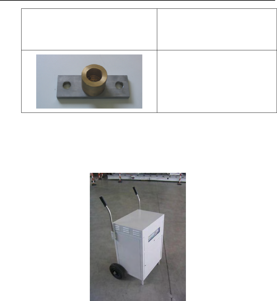
Plate with spherical lodging
Tab. 2.2 – Contents of the IBIS-L case
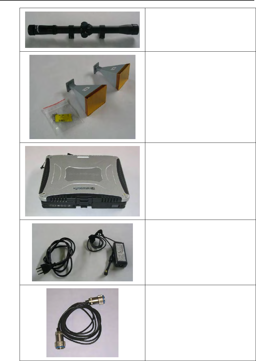
Cardboard Box with dimensions 80x60x100 cm and total weight of 89kg containing
the power supply module and its mains power supply cables (Fig. 2.4).
Fig. 2.4 – Power supply module
IDS Ingegneria Dei Sistemi S.p.A. N°doc: MN/2009/070 - Rev. 1.1
IBIS-L v.02.00 - User manual
26 / 65
All information contained in this document is property of IDS. All rights reserved.
3. IBIS-L SYSTEM HARDWARE CONFIGURATION
This section of the manual provides a detailed description of the components making up
IBIS-L system:
• Par. 3.1 IBIS sensor;
• Par. 3.2 IBIS antennas;
• Par. 3.3 IBIS linear scanner;
• Par. 3.4 Installation kit;
• Par. 3.5 IBIS-PS power supply module;
• Par. 3.6 Control and acquisition PC;
• Par. 3.7 Set of IBIS-C KIT connection cables.
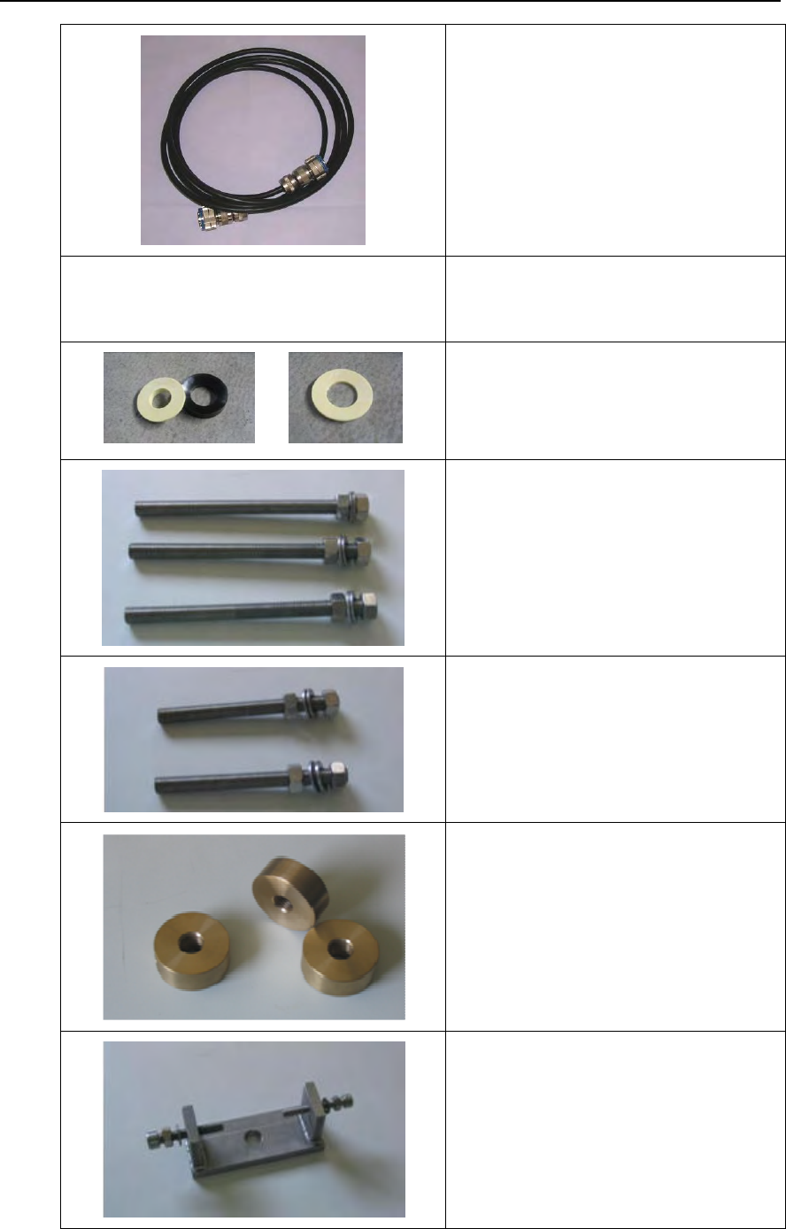
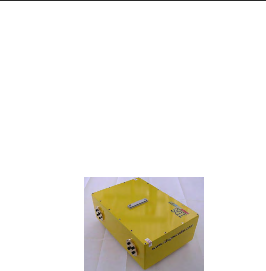
3.1 IBIS sensor
The radar sensor is the unit containing all the parts for the generation, transmission,
reception and acquisition of the radar signal. The sensor is shown in Fig. 3.1 and can be
seen as a yellow box with dimensions 375x270x115 mm.
Fig. 3.1 – IBIS sensor
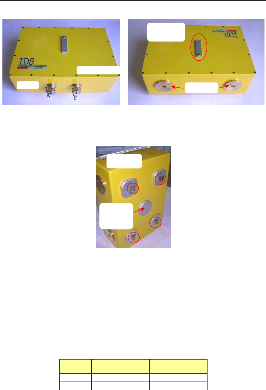
The IBIS sensor has the following interfaces (see Fig. 3.2 and Fig. 3.3):
• 1 USB B type connector at the back of the sensor;
• A 12 pole connector for power supply;
• 2 flanges for installation of the antennas on the front of the box.
• 1 dovetail guide on the top of the box to hold the optical telescope (see par. 4.2).
• 1 threaded screw hole on the bottom of the sensor, required to fix the sensor to
the tripod (for use in IBIS-S configuration.
• 4 clasps on the bottom of the sensor.
IDS Ingegneria Dei Sistemi S.p.A. N°doc: MN/2009/070 - Rev. 1.1
IBIS-L v.02.00 - User manual
27 / 65
All information contained in this document is property of IDS. All rights reserved.
(a)
(b)
Fig. 3.2 – Back (a) and front (b) view of the sensor
Fig. 3.3 – Bottom view of sensor
3.2 Antennas
3.2.1 Ku band system antennas
The Ku band IBIS-L system is provided with two identical IBIS-H20 antennas operating
in vertical polarisation and characterised by a maximum gain of 20dBi. The amplitude
characteristics of the antenna main lobe at -3 dB and -10 dB are provided in Tab. 3.1 and
its vertical and horizontal patterns are shown in Fig. 3.4 and Fig. 3.5. For further details
see appendix B.1 .
IBIS-H20 HORIZONTAL
PLANE VERTICAL
PLANE
-3 dB 17° 15°
-10 dB 34° 45°
Tab. 3.1 – Width of the main lobes of the IBIS-H20 antennas at -3 dB and -10 dB
USB
Dovetail
guide
Power supply
4 claps
Flanges
Threaded
screw
hole
IDS Ingegneria Dei Sistemi S.p.A. N°doc: MN/2009/070 - Rev. 1.1
IBIS-L v.02.00 - User manual
28 / 65
All information contained in this document is property of IDS. All rights reserved.
Fig. 3.4 – IBIS-H20 vertical plane pattern Fig. 3.5 – IBIS-H20 horizontal plane pattern
The sensor is fitted with two flanges, each with four filleted holes for the installation of
the pair of antennas (see par. 4.2).
Fig. 3.6 – IBIS-H20 antenna
If desired as an optional or a substitution, the IBIS-H20 antennas can be replaced by a pair
of three other antennas whose characteristics are reported below:
IBIS-H23 antennas (Type 1) having the following characteristics:
• Maximum gain of 23.5 dBi;
• Horizontal antenna beam width at -3dB: 11deg.
• Vertical antenna beam width at -3dB: 10deg.
IBIS-H15 antennas (Type 3) having the following characteristics:
• Maximum gain of 15 dBi;
• Horizontal antenna beam width at -3dB: 29deg.
• Vertical antenna beam width at -3dB: 25deg.
IBIS-H13 antennas (Type 4) having the following characteristics:
• Maximum gain of 13.5 dBi;
• Horizontal antenna beam width at -3dB: 38deg.
IDS Ingegneria Dei Sistemi S.p.A. N°doc: MN/2009/070 - Rev. 1.1
IBIS-L v.02.00 - User manual
29 / 65
All information contained in this document is property of IDS. All rights reserved.
• Vertical antenna beam width at -3dB: 18deg.
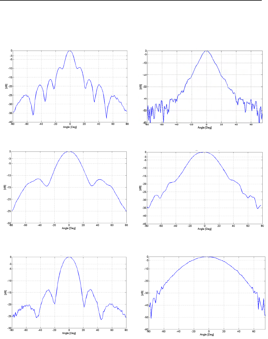
Figure from Fig. 3.7 to Fig. 3.12 show the vertical and horizontal patterns of antenna
Type 1, 3 and 4 and Tab. 3.2 summarizes the information for the all four antenna types.
Fig. 3.7 –IBIS-H23 vertical plane pattern Fig. 3.8 –IBIS-H15 horizontal plane pattern
Fig. 3.9 – IBIS-H15 vertical plane pattern Fig. 3.10 – IBIS-H15 horizontal plane pattern
Fig. 3.11 – IBIS-H13 vertical plane pattern Fig. 3.12 – IBIS-H13 horizontal plane pattern
IDS Ingegneria Dei Sistemi S.p.A. N°doc: MN/2009/070 - Rev. 1.1
IBIS-L v.02.00 - User manual
30 / 65
All information contained in this document is property of IDS. All rights reserved.
Gain Elevation
Azimuth
Antenna Type [dBi]
[deg] [deg]
1 - IBIS-H23
-3 dB azimuth beamwidth 10 11
-10 dB azimuth beamwidth 23,5 30 23
2 - IBISH20
-3 dB azimuth beamwidth 15 17
-10 dB azimuth beamwidth 20 45 34
3 - IBIS-H15
-3 dB azimuth beamwidth 25 29
-10 dB azimuth beamwidth 15 49 53
4 - IBISH13
-3 dB azimuth beamwidth 18 38
-10 dB azimuth beamwidth 13,5 30 70
Tab. 3.2 – Ku band Antennas characteristics
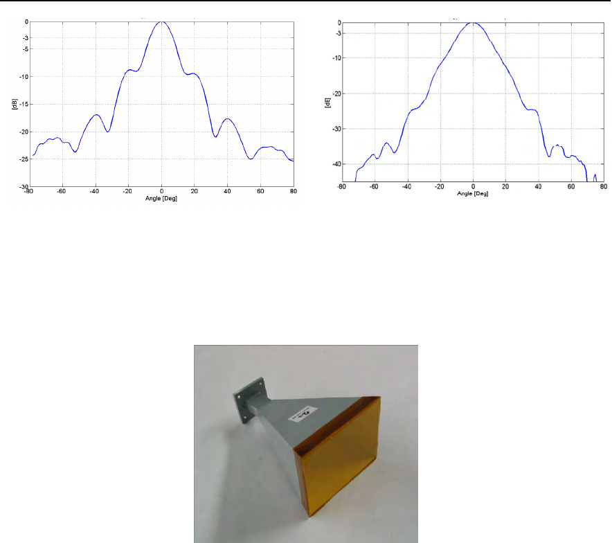
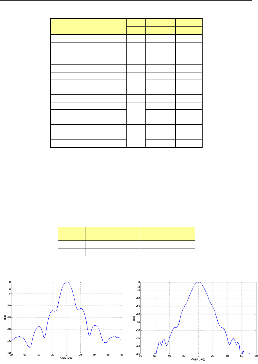
3.2.2 X band system antennas
The X band IBIS-L system is provided with two identical antennas operating in vertical
polarisation and characterised by a maximum gain of 21dBi. The amplitude characteristics
of the antenna main lobe at -3 dB and -10 dB are provided in Tab. 3.3 and its vertical and
horizontal patterns are shown in Fig. 3.13 and Fig. 3.14. For further details see appendix
B.1 .
X band
antenna HORIZONTAL
PLANE VERTICAL
PLANE
-3 dB 15° 15°
-10 dB 27° 25°
Tab. 3.3 – Width of the main lobes of the X band antennas at -3 dB and -10 dB
Fig. 3.13 –X band antenna vertical plane
pattern Fig. 3.14 – X band antenna horizontal plane
pattern
IDS Ingegneria Dei Sistemi S.p.A. N°doc: MN/2009/070 - Rev. 1.1
IBIS-L v.02.00 - User manual
31 / 65
All information contained in this document is property of IDS. All rights reserved.
The sensor is fitted with two flanges, each with four filleted holes for the installation of
the pair of antennas (see par. 4.2).
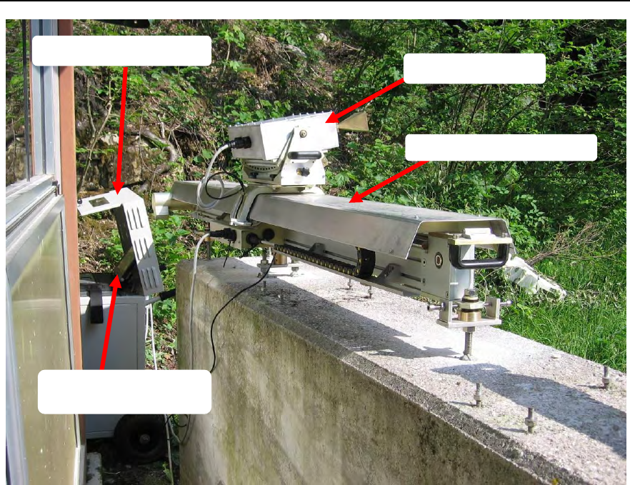
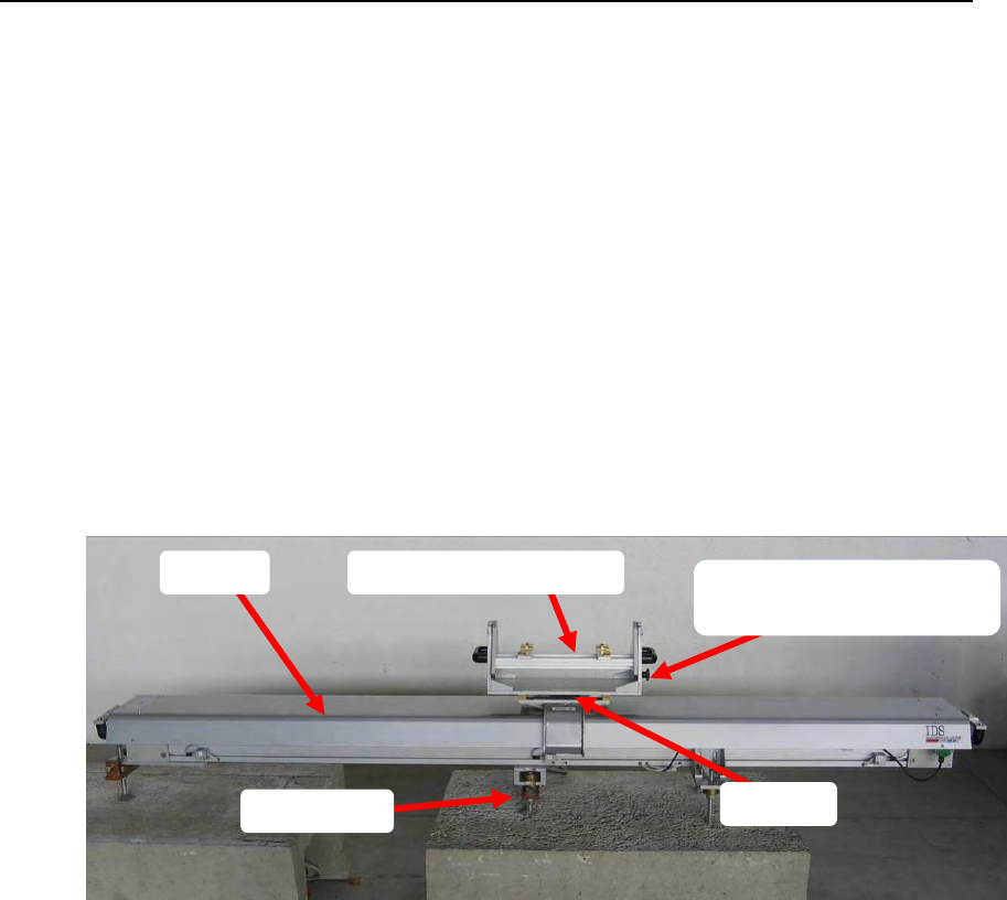
3.3 Linear Scanner
The linear scanner (Fig. 3.15) consists of:
• A 2.5 m long track covered with aluminium sheeting;
• A trolley moved along the track by a step by step motor with a maximum
displacement of 2 m;
• An elevation pointing system to be installed on the trolley.
The elevation pointing system is the support for the IBIS sensor and permits the main
beam of the antenna to be orientated in elevation towards the area to be observed.
Fig. 3.15 – Installed linear scanner
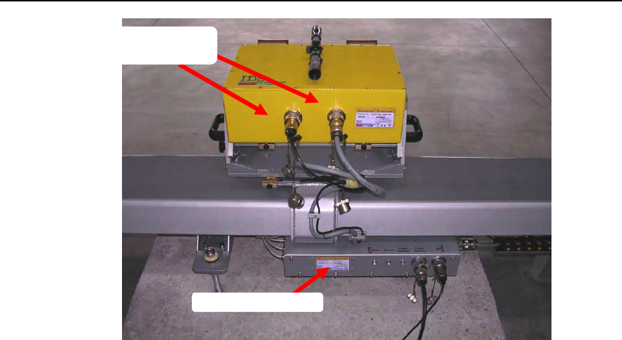
Two mobile connectors link the sliding trolley to the sensor, while the panel at the back of
the linear scanner has the following interfaces:
• A five pin power supply connector;
• A B type USB connector;
to be connected to the power supply unit using the two cables which are part of the IBIS-
C KIT.
Truck
Pointing system
Fixing screw for pointing
system
bogie
base
IDS Ingegneria Dei Sistemi S.p.A. N°doc: MN/2009/070 - Rev. 1.1
IBIS-L v.02.00 - User manual
32 / 65
All information contained in this document is property of IDS. All rights reserved.
Fig. 3.16 – Back of linear scanner
Next to these connectors on the panel, there are three green LEDs which, when lighted,
indicate that the power supply is connected to the trolley positioning sensors, the step by
step motor and the IBIS sensor.
The linear scanner is used to move the sensor in along the track orthogonally to the
irradiating direction (antenna axis). The trolley is moved in steps for a total effective
length of 2 m. There is a waiting period between two successive steps equal to the
functioning time of the IBIS sensor.
For long-term monitoring the instrument must be positioned on a stable solid horizontal
base with minimum dimensions of 2000mm x 800mm x 200mm (length, width and
thickness), i.e. a concrete base. These measurements have been established to guarantee
the necessary robustness and permit the inclination of the linear scanner as required.
The system for fixing the linear scanner to the ground has been designed to allow it to be
accurately repositioned quickly and easily. In case of slow movements this means the
instrument can be used at intervals, over a period of several months, without having to
leave it positioned outdoors for the entire period. It is important to underline that the
expected movement between two discontinuous acquisitions has to be smaller than λ/4,
that is 4.3mm for Ku band system and 7.14mm for X band system, to not encounter in
displacement measurement ambiguity.
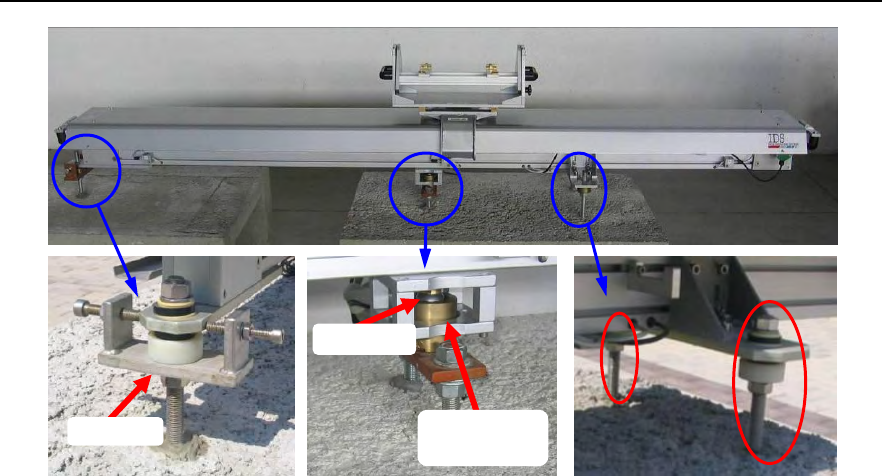
The basic fixture system consists of:
• Three support points (Fig. 3.17) positioned on three studs that fix the plane the
module will slide over.
• A reference sphere positioned under the track and inserted into a specific housing,
and which, when joined to the plane, forms an axis of rotation passing through the
centre of the sphere and normal to the plane.
• A positioning fork providing a buffer to block rotation with respect to the rotation
axis centred on the sphere.
• A screw opposite the buffer to block the module at the buffer point.
Back panel
Mobile
connectors
IDS Ingegneria Dei Sistemi S.p.A. N°doc: MN/2009/070 - Rev. 1.1
IBIS-L v.02.00 - User manual
33 / 65
All information contained in this document is property of IDS. All rights reserved.
(a)
(b)
(c)
Fig. 3.17 – Frontal view of the system for fixing the linear scanner with details of (a)
the positioning fork, (b) housing of the sphere with the sphere inserted and (c) the
two support studs
Sphere
Sphere
housing
Fork
IDS Ingegneria Dei Sistemi S.p.A. N°doc: MN/2009/070 - Rev. 1.1
IBIS-L v.02.00 - User manual
34 / 65
All information contained in this document is property of IDS. All rights reserved.
3.4 Installation kit
The installation kit consists of a template for positioning and drilling holes in the base
(Fig. 3.18) together with a spacer and elements for anchoring the linear scanner as shown
in Fig. 3.19.
Fig. 3.18 – View of the drilling and positioning template with spacer
6 spherical thrust bearings consisting
of two parts and 6 disc springs
3 long M16 nuts, 6 bolts and 6
washers
2 short M16 nuts, 4 bolts and 4
washers
3 base M16 washers
1 positioning fork;
1 spherical housing
Fig. 3.19 – Elements for anchoring the linear scanner
The entire system has been studied to be able to accurately reposition the equipment even
after a long period of time has elapsed. For this reason, once installed, the anchoring
IDS Ingegneria Dei Sistemi S.p.A. N°doc: MN/2009/070 - Rev. 1.1
IBIS-L v.02.00 - User manual
35 / 65
All information contained in this document is property of IDS. All rights reserved.
elements must remain installed at the measurement site since they are the basis of the
positioning reference.
For this reason, when the instrument is dismantled, we recommend you to protect the
anchoring elements with a wooden casing fixed to the base structure with plugs and
screws to avoid them being accidentally damaged or exposed to extreme weather
conditions.
A complete description of the installation procedure is given in par. 4.1
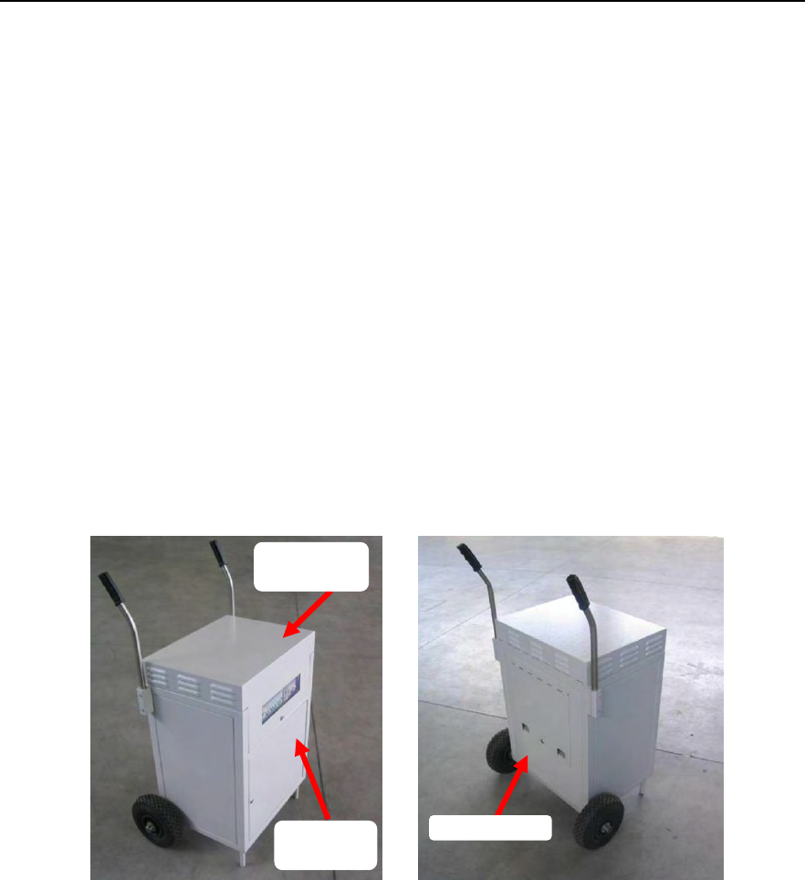
3.5 Power supply module
The power supply module supplies electric power to the system, in detail its function is to:
• Receive power from the mains electricity or from a generator set;
• Charge the pair of batteries required to guarantee continuous power supply even
in the case of a blackout;
• Distribute power and signal to the linear scanner and IBIS-L sensor.
It is a box with dimensions 560x600x840 mm, with two handles, two wheels for ease of
movement and three doors fitted with locks. Fig. 3.20 provides two views of the power
supply module.
Fig. 3.20 – Front (left) and back (right) view of the power supply module. Note the
handles, two wheels and three lockable doors
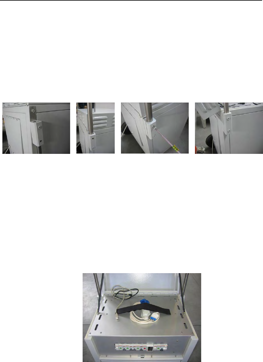
When the power supply unit is delivered, the handles are folded downwards to reduce
bulk and risk of damage during transportation. To reposition the handles proceed as
follows for both handles (following the procedure shown in sequence in Fig. 3.22):
1. completely unscrew the top screw on the handle blocking mechanism and loosen
the lower screw;
2. rotate the handle anticlockwise until it is positioned upright;
3. reinsert and screw in the previously removed screw
4. tighten both screws.
Back door
Top
container
Front
door
IDS Ingegneria Dei Sistemi S.p.A. N°doc: MN/2009/070 - Rev. 1.1
IBIS-L v.02.00 - User manual
36 / 65
All information contained in this document is property of IDS. All rights reserved.
When transporting the module, the handles should always be folded down following the
procedure below:
1. loosen the lower screw of the handle blocking mechanism
2. completely unscrew the top screw on the handle blocking;
3. rotate the handle clockwise (towards the front of the module) until it touches the
wheels;
4. reinsert and screw in the previously removed screw;
5. tighten both screws.
Fig. 3.21 - Sequence for unfolding the power supply unit handles
Opening the top door of the power supply module accesses the housing and work space
for the control and data acquisition PC and the power supply electric switchboard (see
Fig. 3.22). The PC workspace is fitted with:
• A Velcro strap to block the PC;
• A power supply cable for the PC
• A USB cable to connect the PC to the linear scanner and then to the IBIS sensor.
The cable connecting the power supply module to the mains electricity is located
underneath this top door
Fig. 3.22 –The notebook PC table
IDS Ingegneria Dei Sistemi S.p.A. N°doc: MN/2009/070 - Rev. 1.1
IBIS-L v.02.00 - User manual
37 / 65
All information contained in this document is property of IDS. All rights reserved.
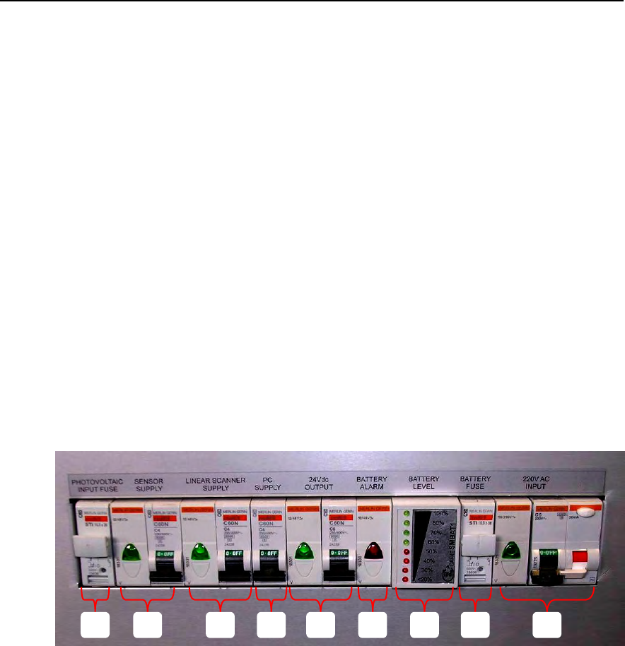
The electric distribution area contains all the system power switches (Fig. 3.22 ). From
left to right we can see:
1. the input fuse from the photovoltaic network;
2. the sensor power supply switch with spy light that illuminates when the sensor is
powered;
3. the linear scanner power supply switch with corresponding spy light;
4. the PC power supply switch;
5. the external power supply source switch (24 V DC) with corresponding spy light;
6. the battery warning light which illuminates when the battery power is low;
7. the battery charge indicator that:
a. shows the charge level of the battery by flashing one of the LEDs when
the battery is being charged or all the switches are off;
b. shows the charge level of the battery by keeping one of the LEDs lit when
the battery is powering one of the instruments but is not being charged;
8. the battery fuse;
9. the switch that controls the power supply input with corresponding spy light and
fuse.
Fig. 3.23 - The power supply module switchboard
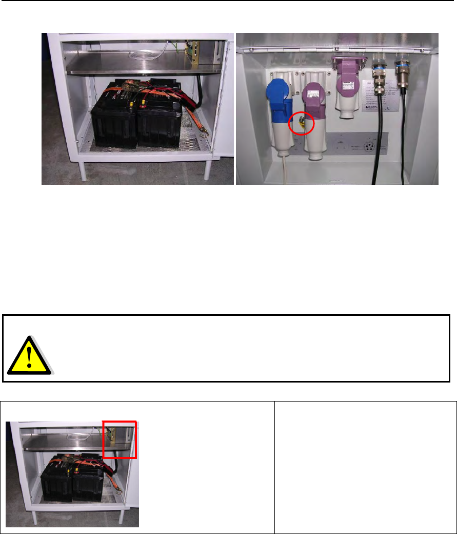
The door on the front of the power supply unit provides access to the battery area
containing a pair of 12 V/70 Ah batteries. The back door gives access to the connector
area, which contains the following connections from left to right:
• the mains AC input (220V or 110V depending on customer request);
• the photovoltaic input, needing an input greater than 24V for battery recharger
with a maximum current of 10A;
• the external auxiliary output at 24V;
• the 5 pole output to the linear scanner;
• the A type USB connection output;
• a screw to link the external box (chassis) of the power supply module to the
ground.
8
2
7
5
3
1
6
9
4
IDS Ingegneria Dei Sistemi S.p.A. N°doc: MN/2009/070 - Rev. 1.1
IBIS-L v.02.00 - User manual
38 / 65
All information contained in this document is property of IDS. All rights reserved.
(a) (b)
Fig. 3.24 - (a) battery housing area, (b) power supply module connector area with the
ground screw highlighted
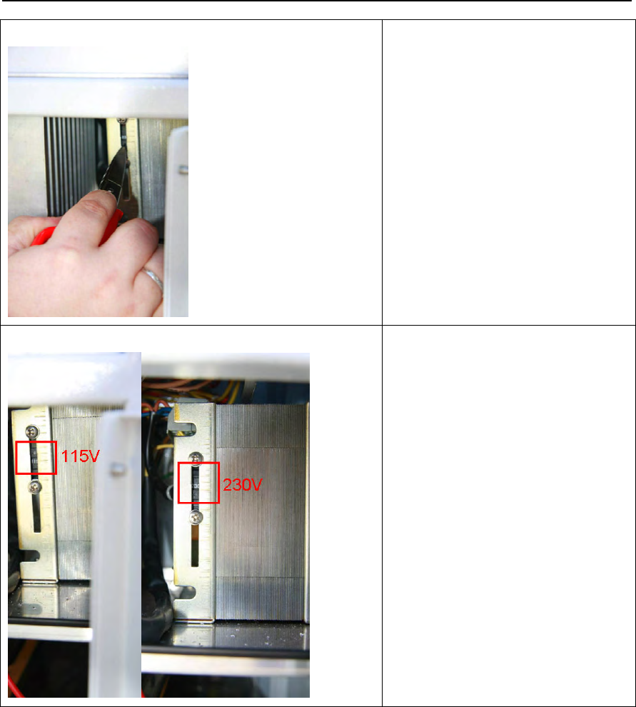
The input voltage must be regulated to correspond to the voltage available on site. This is
done by setting the control on the transformer found behind the front panel as shown in
the following pictures.
1. Make sure you disconnect the
power supply module from the
mains supply before starting the
following procedure.
2. Open the front panel. The
transformer is located in the top
right corner.
WARNING:
ADJUST THE TRANSFORMER VOLTAGE SETTING
IT TO
THE VOLTAGE AVAILABLE ON SITE
BEFORE
CONNECTING THE
APPARATUS TO THE MAINS SUPPLY
IDS Ingegneria Dei Sistemi S.p.A. N°doc: MN/2009/070 - Rev. 1.1
IBIS-L v.02.00 - User manual
39 / 65
All information contained in this document is property of IDS. All rights reserved.
3. Use an insulated tool to move
the switch and select the correct
input voltage value.
4. Verify that the label on the
transformer indicates the desired
voltage. Voltage can be set to
230 V or 115 V.
Tab. 3.4 – Procedure for setting the voltage.
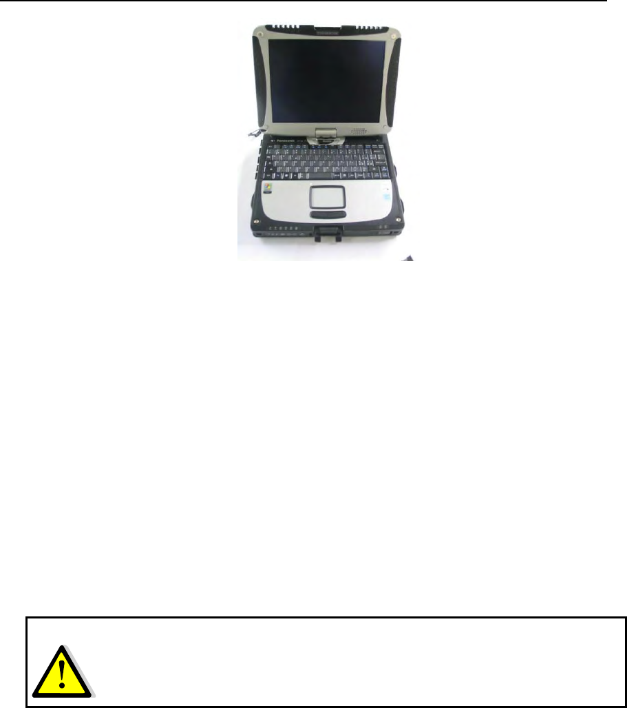
3.6 Control and acquisition PC
The IBIS-L system uses a notebook PC, model PANASONIC CF-19 (Fig. 3.25 ) to
control the sensor. The PC is supplied with windows XP and the IBIS-L Controller v.
02.00.002 control and data acquisition software pre-installed.
IDS Ingegneria Dei Sistemi S.p.A. N°doc: MN/2009/070 - Rev. 1.1
IBIS-L v.02.00 - User manual
40 / 65
All information contained in this document is property of IDS. All rights reserved.
Fig. 3.25 – Panasonic CF-19 PC
The supplied PC has the following characteristics:
• Intel U2400 core duo processor;
• 100 Mb/s Ethernet card;
• RAM 512 MB memory ;
• max monitor resolution 1024x768 pixels;
• max number of colours 16.777.216 colours;
• Windows XP Professional operative system;
• HDD 80 GB, shock-proof (mounted on gel support or equivalent);
• Protection from atmospheric agents (conforms to IP54).
• No communication software such as Firewall, WiFi or antivirus must be installed
to avoid any conflict with the IBIS Controller v. 1.0 software;
The PC is supplied with a mains adapter (220V)
3.7 Connection cable kit
The IBISL-C KIT contains three cables:
• A 3 m long USB cable to connect the power supply module with the linear
scanner;
• A 3 m long power supply and signal cable to connect the power supply module to
the linear scanner;
• A mains power supply cable
NOTE
: IDS takes no responsibility for malfunctioning if there is a functional conflict between
its software and any software installed on the notebook PC by the user. IDS does not
guarantee that the performance of its equipment will be maintained using a
configuration different to that recommended.
IDS Ingegneria Dei Sistemi S.p.A. N°doc: MN/2009/070 - Rev. 1.1
IBIS-L v.02.00 - User manual
41 / 65
All information contained in this document is property of IDS. All rights reserved.
and two plugs:
• one plug for the output towards an external auxiliary;
• one plug for input from a photovoltaic panel;
It is left to the user to choose the appropriate length of cable and type of plug for the other
end of the cable suitable for the specific operational requirements.
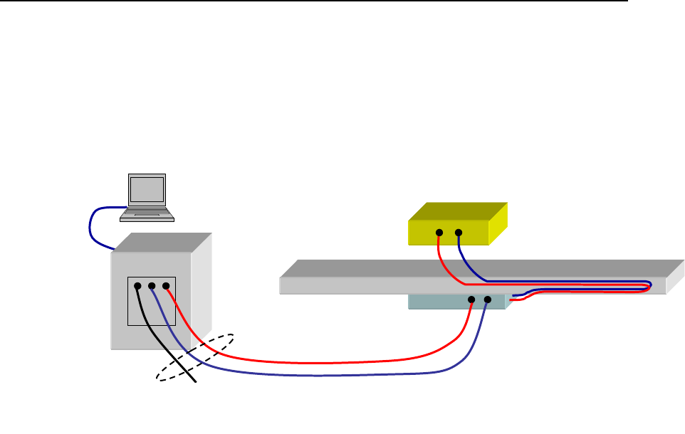
Sensore
IBIS
Modulo
Posizionatore
Modulo
Alimentatore
USB
Alimentazione
Alimentazione
di rete (220Vac)
PC
KIT Cavi
IBIS-L
Fig. 3.26 – Schematic diagram of connections
Power
supply
module
Cables kit Mains power
supply
Power supply
Linear
scanner
IBIS
sensor

IDS Ingegneria Dei Sistemi S.p.A. N°doc: MN/2009/070 - Rev. 1.1
IBIS-L v.02.00 - User manual
42 / 65
All information contained in this document is property of IDS. All rights reserved.
4. IBIS-L SYSTEM INSTALLATION PROCEDURE
Installation of the IBIS-L system requires about 2 hours work to install plus the time
required to build the base and the setting time for the two component resin used to fix the
studs (about 30 minutes at 25°C). The procedure can be broken down into two parts:
1. Installation of the linear scanner;
2. Installation of the IBIS-L sensor and connection of the modules.
After these two procedures have been described, the procedure for dismantling the
equipment form the measurement site is given in Par. 4.3.
4.1 Installation of the linear scanner
The procedure starts with an initial inspection of the site, during which the location for the
installation must be established, and finishes with the installation of the linear scanner.
Note that when re-positioning the module on a pre-existing installation site, only the small
group of operations indicated in par 4.1.3 are required, which relate to the setting up of the
linear scanner.
4.1.1 Material required
The following material is required to install the linear scanner:
1. a solid and stable base in concrete or other non-conductive material that is
sufficiently wide, flat and horizontal; minimum dimensions: 2000mm x 800mm x
200mm (length, width, thickness) (see Par.6.1);
2. IBIS-L box containing the linear scanner;
3. IBIS-L trolley case complete with anchoring elements;
4. spirit level (not supplied);
5. carpentry tools (not supplied) including:
a. hammer drill;
b. set of three masonry drill bots ∅ 8, ∅ 14 e ∅ 18 mm and two metal bits
∅ 20 and ∅ 22 (see par. 6.1);
c. two 24mm spanners;
d. spray, pencil or marker pen to mark the holes;
e. compressed air cylinder to clean debris from the holes made in the base;
f. water repellent silicon grease;
g. water repellent silicon oil;
h. two component resin with dispensing spout and cartridge gun.
To remove the components from the IBIS-L box:
NOTE
: IDS supplies the kit for the first installation. If multiple installations are to be
made, a kit must be acquired for each successive installation.
IDS Ingegneria Dei Sistemi S.p.A. N°doc: MN/2009/070 - Rev. 1.1
IBIS-L v.02.00 - User manual
43 / 65
All information contained in this document is property of IDS. All rights reserved.
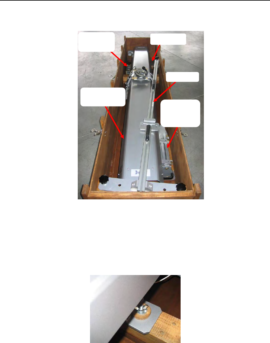
1. ay the case on a flat surface, open the six clasps and remove the cover;
Fig. 4.1 - Opened IBIS-L box
2. remove the template from the case, lifting it by the two black handles;
3. unscrew the three wing nuts that fix the track and remove the washers (Fig. 4.2);
4. remove the track using the handles at each end;
Fig. 4.2 – wing nuts fixing the linear scanner
5. the pointing system is now visible inside the box, the DEM spacers and the template
spacer (Fig. 4.3 );
DEM
elements
Linear
scanner
Elevation
pointing
system
Templat
Spacer
IDS Ingegneria Dei Sistemi S.p.A. N°doc: MN/2009/070 - Rev. 1.1
IBIS-L v.02.00 - User manual
44 / 65
All information contained in this document is property of IDS. All rights reserved.
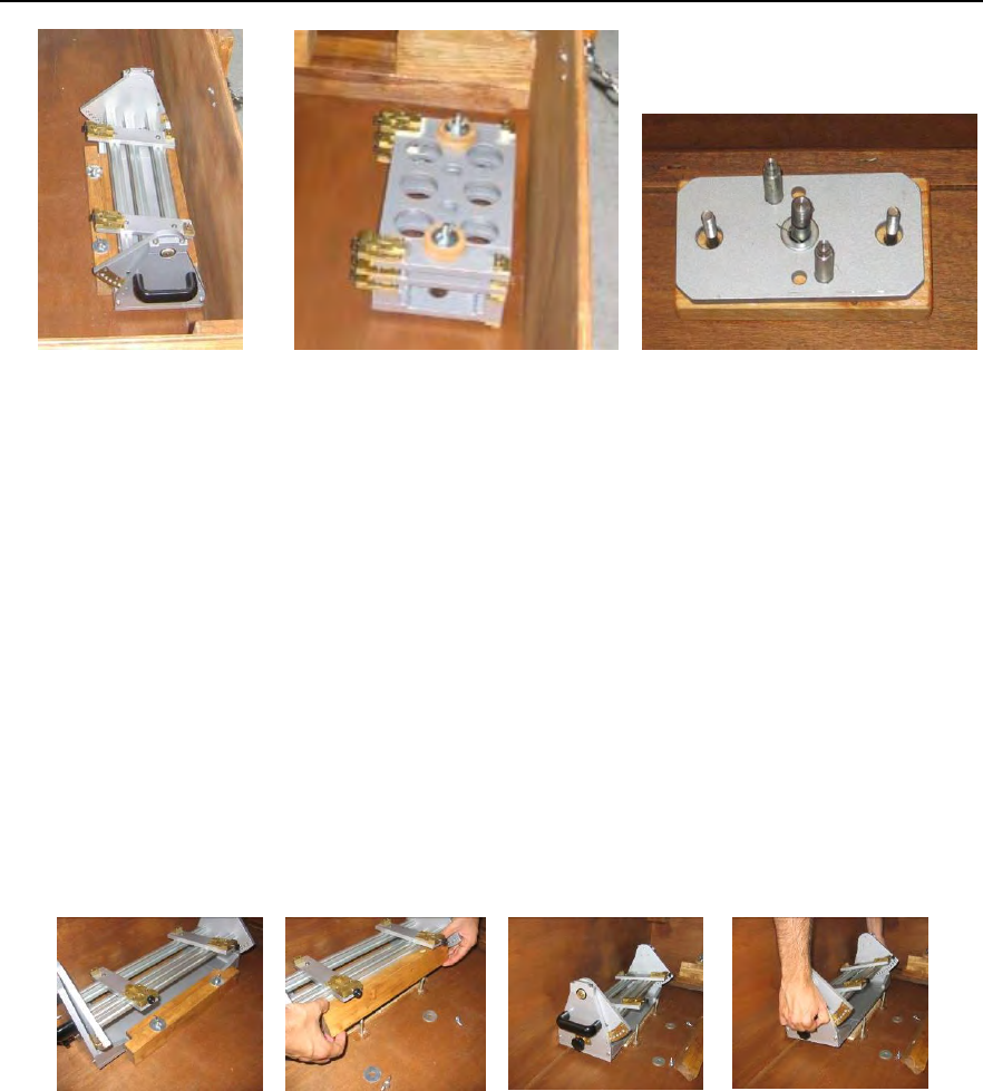
(a)
(b)
(c)
Fig. 4.3 – (a) pointing system, (b) DEM spacers (c) template spacer
6. unscrew the two screws fixing the elevation pointing system and remove the washers.
The entire sequence from point 6 to 8 is shown in Fig. 4.3
7. remove the wooden insert the wing nut were fixed to, lifting it and rotating it slightly
towards the outside of the case
8. remove the elevation pointing system, first rotating it, lifting just the part facing
towards the centre of the box , then sliding it horizontally;
9. unscrew the wing nuts fixing the template spacer and remove the template;
If the DEM spacers are necessary, continue as follows
10. unscrew the two wing nuts that fix the spacers and extract the two screws;
11. now extract the DEM spacers.
Fig. 4.4 – Sequence for removing the elevation pointing system
In order to avoid losing the fixing wing nuts and washers, reinsert the washers and screw
back the wing nuts onto the filleted studs.
To reassemble the box, perform the following steps
1. unscrew all the wing nuts and remove all the washers;
2. insert the DEM spacers onto their studs, making sure the black knobs are pointing
towards the centre of the case as shown in Fig. 4.3 (b);
3. insert the two washers onto the studs and screw on the wing nuts;
4. insert spacer onto its two studs;
5. fix it by inserting the two washers and screwing the two wing nuts;
IDS Ingegneria Dei Sistemi S.p.A. N°doc: MN/2009/070 - Rev. 1.1
IBIS-L v.02.00 - User manual
45 / 65
All information contained in this document is property of IDS. All rights reserved.
6. block the elevation positioning system at the 5th holes counting from the antenna side
in such a way that 5 holes protrude from the back of the pointing system (where the
black knobs are located) (see Fig. 4.3 (a) and Fig. 4.4);
7. orientate the black knobs towards the centre of the box (see Fig. 4.3 (a));
8. tilt the pointing system, lifting the part facing the centre of the box;
9. keeping it tilted, insert the part facing the outside of the box under the protruding part
of the case, being careful to centre it well and completely insert it;
10. rotate the pointing system until it is positioned on the bottom of the case;
11. position the wooden insert on its studs, keeping it slightly tilted towards the outside of
the case;
12. insert the two washes and wing nuts onto the insert studs and tighten them;
13. insert the linear scanner into the case on its three studs (ensure that the linear scanner
trolley is positioned on the middle of the back panel of the linear scanner);
14. insert the three washers and wing nuts and tighten;
15. completely screw in the three template studs;
16. insert the template in the three holes provided;
17. close the box with its lid;
18. secure the box with the six clasps.
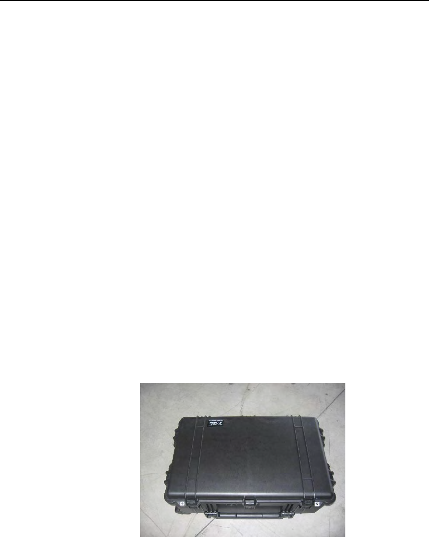
To remove the parts from the IBIS-L case, proceed as follows:
1. sit the case on the ground, open the 7 clasps and lift of the cover;
Fig. 4.5 – IBIS-L case
2. after removing the protective layer , you can see:
a. 1 anchoring element;
b. 1 optical telescope;
c. 1 USB cable and one power supply cable for the sensor;
d. 2 locks;
IDS Ingegneria Dei Sistemi S.p.A. N°doc: MN/2009/070 - Rev. 1.1
IBIS-L v.02.00 - User manual
46 / 65
All information contained in this document is property of IDS. All rights reserved.
If the system has been purchased in both S and L configuration, the anchoring elements
are provided in a separate box.
Fig. 4.6 – IBIS-L case - internal view
3. remove the Panasonic PC, the optical telescope , the USB cable and power supply
cable for the sensor;
4. at this point the following parts are visible :
a. 1 pair of H20 antennas (or optional H15 antennas);
b. 1 mains electricity power transformer for the PC;
c. 1 IBIS-L sensor.
Fig. 4.7 – IBIS-L case - internal view
USB cable
PC-Sensor
Notebook
Installation kit
Power supply
cable
Optical
telescope
IBIS
Sensor
Antennas
IBIS-L H20
Mains electricity
power transformer
IDS Ingegneria Dei Sistemi S.p.A. N°doc: MN/2009/070 - Rev. 1.1
IBIS-L v.02.00 - User manual
47 / 65
All information contained in this document is property of IDS. All rights reserved.
NOTE
: The instrument observation direction is perpendicular to the template axis; the correct
observation direction is when standing looking at the template, you have two
regulation screws to your left and a single screw to your right (see Fig.4.2).
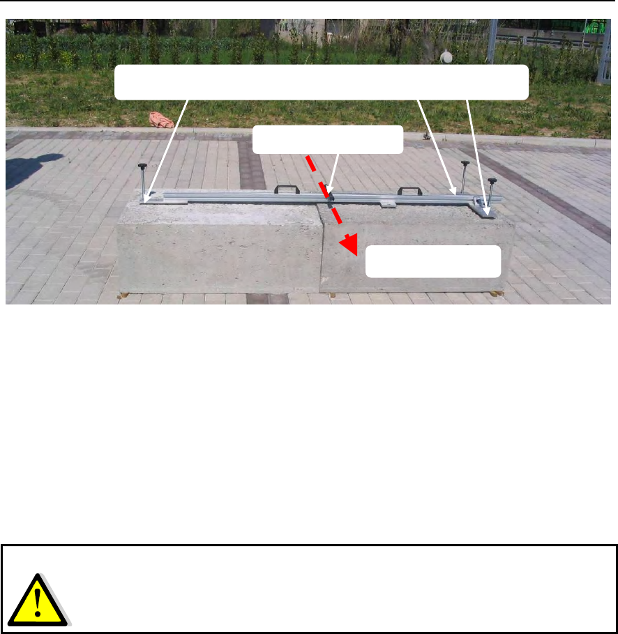
Fig. 4.8 – View of the template placed on the base
4.1.2 Preparing the anchor points for the linear scanner
This section describes the sequence of operations to be performed to set up the linear
scanner anchoring elements
1. position the three template height regulating screws as low as possible (see Fig. 4.8 );
2. mount the optical view finder on the template;
3. place the template on the base;
4. use the optical telescope to point at the scenario to be monitored, orientating the template
on the base surface. When choosing the area to be monitored, take the width of the
antenna beam into consideration (see par. 3.2);
5. use the spirit level to make sure the template is perfectly horizontal by turning the handles
of the three threaded screws, making sure you do not raise the template too far from the
surface of the base;
6. mark the position of the 5 large holes (∅16 mm) present on the template onto the base;
7. remove the template and drill 18 mm holes for the studs to a depth of about 11 cm,
carefully clean the holes with compressed air. Be careful to keep the drill vertical to avoid
the need to widen the holes later;
8. mount the spacer, screwing it to the two smallest holes present on the central plate of the
template (Fig. 4.9);
9. mount the three long studs, inserting them into the three holes at the ends of the template
with the nut and lock nut and insert the washers (Fig. 4.9), controlling that the stud
protrudes from the upper nut by about at approximately 4cm;
Adjustment screws position in order to mark out holes
Optical telescope
Observation way
IDS Ingegneria Dei Sistemi S.p.A. N°doc: MN/2009/070 - Rev. 1.1
IBIS-L v.02.00 - User manual
48 / 65
All information contained in this document is property of IDS. All rights reserved.
Fig. 4.9 – Mounting the studs on the template, detail of the central plate with the
spacer and its two studs
10. mount the two shorter studs on the spacer with the nut, lock nut and M16 washer (Fig.
4.9) so they protrude from below the template the same distance as the other three studs
(all 5 studs must touch the ground at the same time);
11. minimising the protrudance of the three regulating screws, replace the template with these
studs onto the base, inserting the studs into the previously drilled holes and ensuring that
all the studs enter easily into the holes without any obstacles;
12. move the studs fixed to the template in and out of the holes on the base several times to
ensure that they enter well to the correct depth (widen the diameter of the holes if
necessary);
13. use the template regulating screws to fix the height position of the studs so that they
penetrate about 7-8 cm inside the respective holes;
14. place the template in the exact position and level it using the three regulating screws;
15. remove the template from the base, keeping all the studs and screws attached to it;
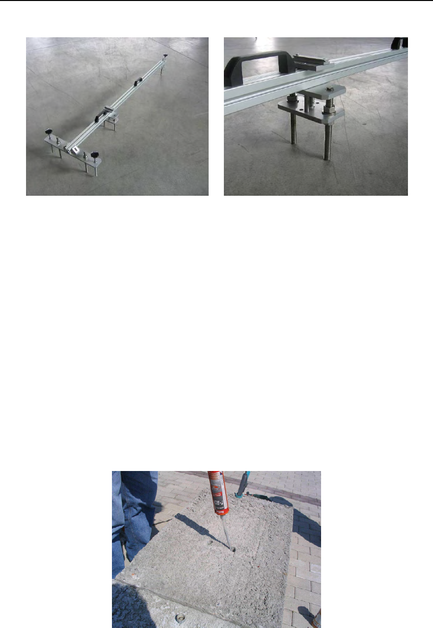
Fig. 4.10 – Resin injection operation
IDS Ingegneria Dei Sistemi S.p.A. N°doc: MN/2009/070 - Rev. 1.1
IBIS-L v.02.00 - User manual
49 / 65
All information contained in this document is property of IDS. All rights reserved.
16. inject enough resin into each hole to block the studs (Fig. 4.10 );
17. insert the studs, still attached to the template, into the holes making sure that the position
coincides with that previously measured;
18. wait for the resin to dry completely (for the time required, read the instructions on the
tube), then remove the 5 nuts and the M16 washers that keep the studs fixed to the
template and lift off the template (the base should now be left with the five studs with 5
nuts and 5 M16 washers).
4.1.3 Mounting the linear scanner
The following sequence of operations describes the installation of the linear scanner onto
the anchoring elements:
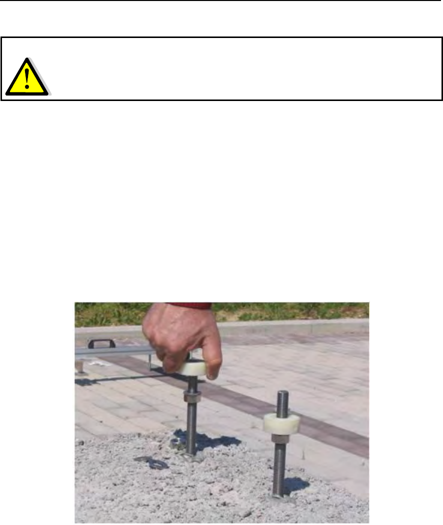
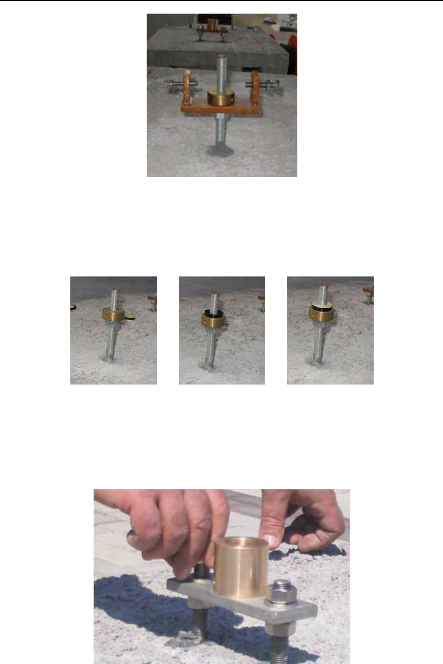
1. mount the two base washers on the two closely positioned studs (Fig. 4.11);
Fig. 4.11 – Mounting the base washers
2. fix the positioning fork on the other stud on the opposite side of the base, positioning it
with the axis of the two screws perpendicular to the direction of the axis of the template;
3. screw the third base washer above the positioning fork (Fig. 4.12);
NOTE
: the resin is malleable for about 5 minutes before setting at summer temperatures, so the
time between the moment of the first injection to the insertion of the studs into the resin
filled holes must be less than this to avoid the need to drill new holes.
IDS Ingegneria Dei Sistemi S.p.A. N°doc: MN/2009/070 - Rev. 1.1
IBIS-L v.02.00 - User manual
50 / 65
All information contained in this document is property of IDS. All rights reserved.
Fig. 4.12 – The correctly installed positioning fork
4. mount the concave part (black color) of the three spherical thrust bearings onto the three
washers and lubricate them with the water-repellent silicon oil;
5. mount the convex part (white colour) of the three spherical thrust bearings (Fig. 4.13);
Fig. 4.13 – Sequence for mounting the spherical thrust bearings
6. insert the plate with the spherical housing onto the two short central studs, sitting it on the
washers and the two nuts already screwed onto the stud;
Fig. 4.14 – Mounting the fixing plate to the spherical housing
IDS Ingegneria Dei Sistemi S.p.A. N°doc: MN/2009/070 - Rev. 1.1
IBIS-L v.02.00 - User manual
51 / 65
All information contained in this document is property of IDS. All rights reserved.
7. grease the spherical housing with silicon waterproof grease;
8. place the track on the three spherical thrust bearings, making sure that the sphere is
properly positioned in its housing;
9. level and position the track by regulating the base washers and the spherical housing
plate;
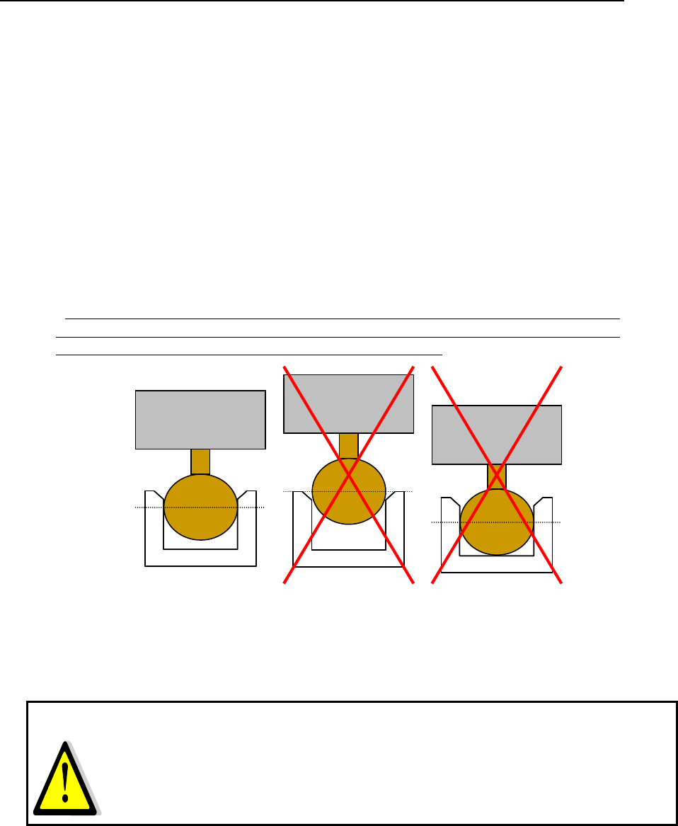
10. regulate the height of the spherical housing plate so that the sphere is positioned in its
housing a little further than its maximum circumference (Fig. 4.15) but without touching
the bottom;
11. check the spherical housing is level, it is easier to perform this operation after removing
the linear scanner;
12. tighten the spherical housing plate tighten the nuts against the base washers, making sure
that the three washers do not rotate thus loosing the position obtained previously , and that
the fork is in the correct position, perpendicular to the axis of the track.
(WARNING: IN ORDER TO CONSERVE THE REFERENCE POSITION, THE
POSITION OF THE BASE WASHERS AND THE SPHERICAL HOUSING FIXED AT
THIS POINT MUST NOT BE MODIFIED FROM NOW ON)
OK NO NO
Linear
Scanner
Sphere
Sphere housing
Fig. 4.15 – Contact between the spherical housing and the sphere. Left shows the correct
position, centre shows the sphere position too high, right shows the sphere touching the
bottom of the housing
13. reposition the linear scanner on the three studs;
14. block the positioning fork M10 buffer screw with the lock nut and M10 washer, taking
care that the stud remains in the centre of the flange hole to permit the track to
elongate/contract due to thermal excursions. Use a marker pen (or a little resin or wax) to
mark the position of the nut with respect to the positioning fork so as to have a reference
for repositioning the linear scanner, since the nut cannot be moved after it has been fixed;
NOTE
: be especially careful when mounting the positioning sphere, which is fundamental when
repositioning the instrument. The spherical housing is countersunk to make the insertion of
the sphere easier, so the maximum circumference of the sphere should pass this
countersinking without touching the bottom of the spherical housing, to ensure the
reference is high precision. Regulate the height of the spherical housing plate until this is
achieved.
Linear
Scanner
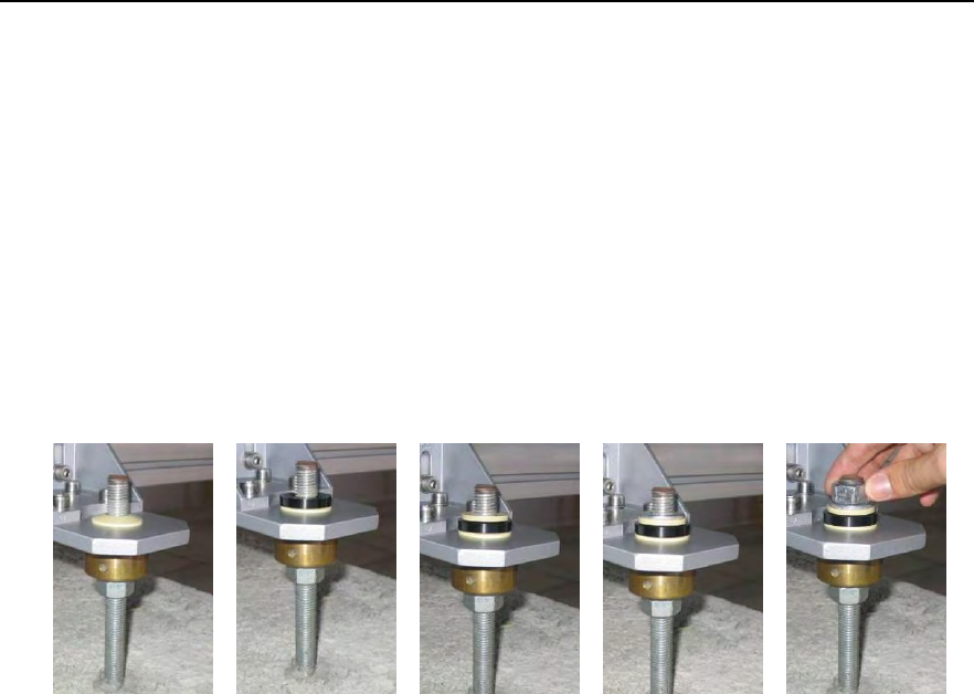
IDS Ingegneria Dei Sistemi S.p.A. N°doc: MN/2009/070 - Rev. 1.1
IBIS-L v.02.00 - User manual
52 / 65
All information contained in this document is property of IDS. All rights reserved.
15. hand tighten the M8 anti veering screw and lock it with an M8 washer and lock nut so that
it keeps the linear scanner flange fixed, without there being any play between the two
screws, but keeping it free to slide for any elongation/contraction due to thermal
excursions undergone while the instrument is positioned at the measurement site;
16. place the three remaining spherical thrust bearings, convex side uppermost, onto the three
external studs (the ones that have the track supports inserted), lubricate them with the
water repellent silicon grease and position the concave parts of each one on top of them
(Fig. 4.16);
17. now insert two disc springs and an M16 washer on each of these studs (Fig. 4.16);
18. screw on the M16 fixing nuts to these three studs and hand tighten them, being careful not
to tighten them too much (the disc springs must remain a little open) (Fig. 4.16).
Fig. 4.16 – Steps 16 to 18
The suspension function provided by the spherical thrust bearings maintains the support
horizontal and compensates for any deviation of the position of the studs from the axis
with respect to the horizontal plane of the track, while the springs keep the track fixed to
the supports while permitting it to undergo normal expansion.
When the linear scanner is reinstalled onto an existing installation site, the operations to
be performed are those described in points 4, 5, 8 and then from points 15 to 18 of this
paragraph. The module to be repositioned must simply be placed on the spherical thrust
bearings and then fixed with the M16 nuts and the M8 screw, without touching the
position of the base washers.
4.2 Installation of the IBIS sensor and module connection
After having installed linear scanner, the IBIS sensor can be installed on the trolley. To do
this, the following operations must be performed in sequence:
1. loosen the two knobs on the trolley dovetail guides sufficiently to permit the
insertion of the elevation pointing system (the sequence of points 1 to 3 is shown
in Fig. 4.17);
2. keeping the pointing system tilted downwards, align the two front pairs of
dovetail guides then rotate the elevation pointing system resting it on the trolley
(loosen further the knobs if it does not completely rest on the trolley);
3. tighten the two knobs;
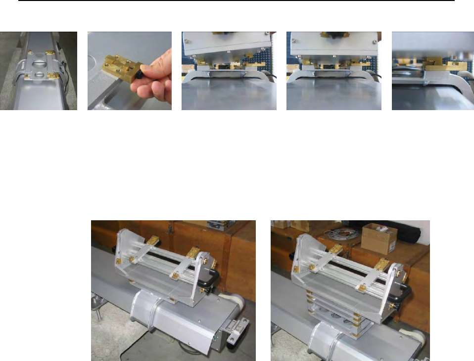
IDS Ingegneria Dei Sistemi S.p.A. N°doc: MN/2009/070 - Rev. 1.1
IBIS-L v.02.00 - User manual
53 / 65
All information contained in this document is property of IDS. All rights reserved.
Fig. 4.17 - positioning the elevation pointing system onto the linear scanner
If it the DEM spacers are required, these should be inserted between the trolley and
the elevation pointing system as indicated in Fig. 4.18 (b), following the same
sequence described for the elevation positioning system (points 1-3).
(a)
(b)
Fig. 4.18 – Correctly installed elevation pointing system (a) without and (b) with the
DEM spacers
4. use the same procedure to position the IBIS sensor onto the elevation pointing
system, making sure that the connection flanges are positioned on the side
labelled “antenna side” on the linear scanner and the pointing system;
5. mount the optical view finder onto its guide located on the lid of sensor and lock
it on with its screws (the label on the optical telescope should point in the viewing
direction);
6. mount the two IBIS antennas onto the IBIS sensor, using the supplied screw (4 for
each antenna);
7. unscrew the elevation pointing system fixing nuts and rotate the sensor until it is
pointing in the desired direction using the optical telescope;
8. tighten the fixing nuts again in the hole nearest to the desired position;
9. remove the optical telescope from the sensor;
10. remove the protective caps from the IBIS-L sensor and linear scanner connectors;
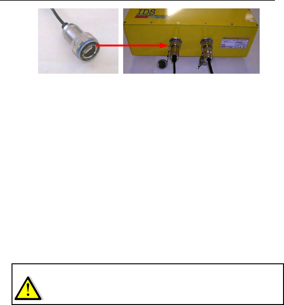
IDS Ingegneria Dei Sistemi S.p.A. N°doc: MN/2009/070 - Rev. 1.1
IBIS-L v.02.00 - User manual
54 / 65
All information contained in this document is property of IDS. All rights reserved.
Fig. 4.19 - Left and centre: detail of the IBIS sensor connector. Right: two protective
caps for the connectors
11. connect the power supply cable and the USB cable that are fixed to the trolley of
the linear scanner to the appropriate connectors on the IBIS sensor, being careful
to insert them fully and completely tighten the external ring to ensure the
connections are waterproof;
12. locate the power supply module close to the linear scanner and connect the linear
scanner to the power supply;
13. connect the power supply module to the linear scanner with the USB cable and
the power supply cable from the IBIS-L C KIT, making sure that the external ring
on each connecter is fully tightened (Fig. 4.20);
14. position the PC in the upper section of the power supply module, fixing it with the
Velcro harness system;
15. connect the PC power supply cable provided in the power supply module to the
appropriate socket in the PC.
In Fig. 4.21 the fully installed IBIS-L system is shown.
NOTE
: for safety of the operators, remember to connect the equipment to the ground using
the reference screw available in the rear side of the power supply module.
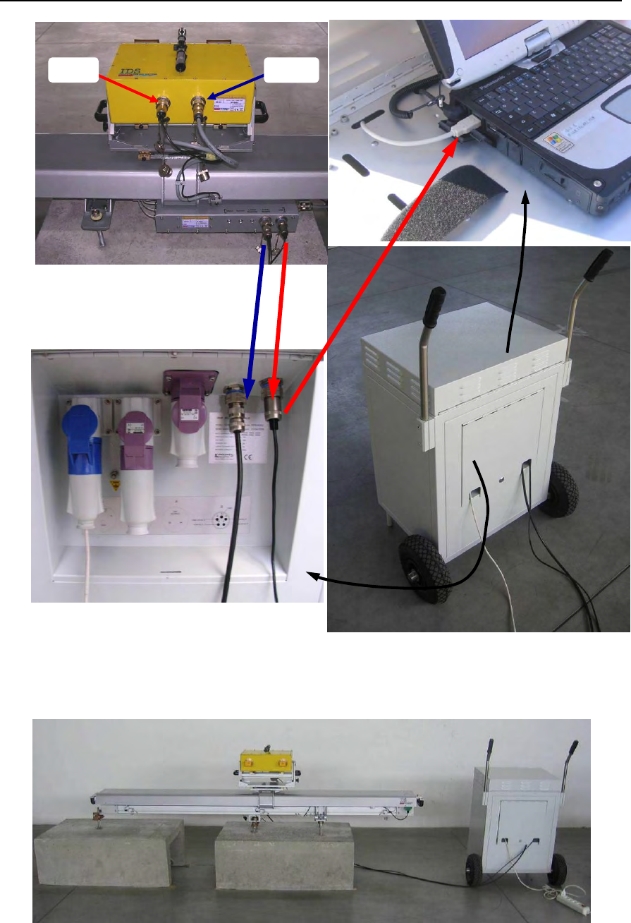
IDS Ingegneria Dei Sistemi S.p.A. N°doc: MN/2009/070 - Rev. 1.1
IBIS-L v.02.00 - User manual
55 / 65
All information contained in this document is property of IDS. All rights reserved.
Fig. 4.20 – Connections between IBIS sensor - linear scanner –power supply module
-PC
Fig. 4.21 – Fully installed IBIS-L system
USB
ALIM

IDS Ingegneria Dei Sistemi S.p.A. N°doc: MN/2009/070 - Rev. 1.1
IBIS-L v.02.00 - User manual
56 / 65
All information contained in this document is property of IDS. All rights reserved.
4.3 Dismantling the measurement site
The following procedure should be followed to remove the instrument from the
measurement site:
1. disconnect the cables connecting the IBIS sensor to the linear scanner,
unscrewing the rings and pulling them out from the sensor connectors;
2. disconnect the cables connecting the linear scanner to the power supply module,
unscrewing them then pulling them out;
3. screw the protective caps onto the two IBIS connectors and the two flexible linear
scanner connectors;
4. unscrew the knobs on the dovetail guides;
5. remove the IBIS sensor and place it in the case;
6. remove the trolley, loosening the four knobs that block the dovetail guides that fix
it to the linear scanner and position it in its space in the IBIS-L box;
7. tighten the knobs back onto the dovetail guides to endure they are not lost or
damaged during transportation;
8. unscrew the three M16 nuts mounted on the studs at the two ends of the module;
9. remove the washers, disc springs and spherical thrust bearings from the three
studs;
10. unscrew the M8 lock nuts and the nuts to free the linear scanner;
11. replace all the DEM spacers back into the IBIS-L box as described in par. 4.1.1;
12. lift the linear scanner and place it in the IBIS-L box;
13. close the case after checking all parts have been packed and wing nuts tightened;
14. replace all cables, the optical telescope and the antennas in the IBIS-L trolley
case.
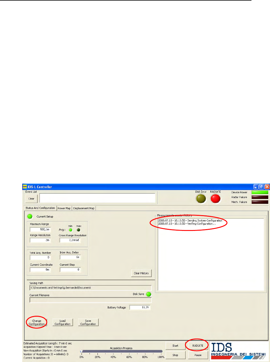
IDS Ingegneria Dei Sistemi S.p.A. N°doc: MN/2009/070 - Rev. 1.1
IBIS-L v.02.00 - User manual
57 / 65
All information contained in this document is property of IDS. All rights reserved.
5. FIRST START UP
Once the instrument has been installed according to instructions, it is ready for use. The
following list describes the operations requires to start up and use IBIS-L:
1. if necessary, connect the power supply module to an external power supply
using the cable supplied in the upper area of the power supply module and
switch on the switch that controls input from mains (external AC input). This
mode avoids using the charged batteries.
2. start up the control ad acquisition PC;
3. switch on the three switches on the power supply module that control :
a. the sensor (sensor power supply);
b. linear scanner (linear scanner power supply );
c. pc power supply (Lap Top PC );
4. connect the USB connector in the upper area of the power supply module to
the PC (it is always best to connect it after having switched on all the
equipment to avoid any possible recognition problems of the USB device by
the operative system);
5. start the IBIS-L Controller v. 02.00.002 program clicking on the desktop icon;
Fig. 5.1 - Opening window of the control and acquisition software
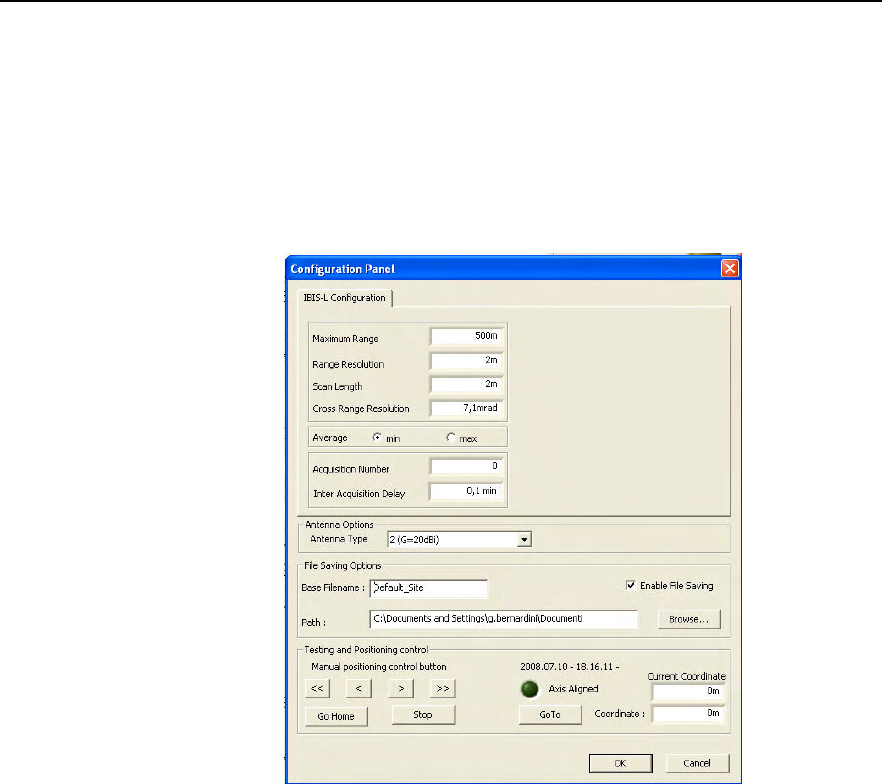
IDS Ingegneria Dei Sistemi S.p.A. N°doc: MN/2009/070 - Rev. 1.1
IBIS-L v.02.00 - User manual
58 / 65
All information contained in this document is property of IDS. All rights reserved.
6. once started, the program performs a rapid check up of the peripheries and is
ready for use (the measurement session history panel displays the “verifying
configuration” message);
7. to check the correct functioning of the apparatus, click the Change
Configuration button and from the Configuration Panel that opens. Try to
move the sensor along the track using the buttons located in the bottom left of
the window (<<, <, >, >> and STOP). Then press the go home command,
which returns the sensor to the centre of the linear scanner;
Fig. 5.2 – The configuration panel
8. once the sensor Homing operation is completes, press OK;
9. check that the system has accepted the configuration (the “Configuration
Changed” message appears in the Measurement’s Session History panel).
At this point, the instrument can be used following the instructions provided in the IBIS-L
Controller software manual.

IDS Ingegneria Dei Sistemi S.p.A. N°doc: MN/2009/070 - Rev. 1.1
IBIS-L v.02.00 - User manual
59 / 65
All information contained in this document is property of IDS. All rights reserved.
6. USEFUL TIPS
6.1 Installation
The successful outcome of a measurement campaign starts from the initial inspection
survey: the first main aim of the inspection survey is to establish the exact position of the
base that the linear scanner will be installed onto.
The characteristics of a good position are to:
• be in the direction of the displacement to be measured;
• have sufficient space to operate safely and to have room for the linear
scanner, the power supply module and the operators;
• be easily accessible for the transportation of material (remember that the
packing case weighs 107 kg and is bulky to move);
• have an external power supply. If this is impossible, a power generator must
be supplied;
During the inspection survey, it is also useful to perform a GPS measurement of the
position the instrument will have, and of the area to be monitored, obtain maps, including
3D maps or DEM of the area and ensure that all necessary permits have been obtained for
the construction of the base and monitoring the area of interest. It is always a
recommended to inform the competent authorities.
It is recommended to check sufficiently in advance that the contents of the case have been
properly loaded to avoid any damage during transportation, ensure that the power supply
module batteries have been fully charged (see par 3.5) and arrange a suitable means of
transport capable of containing all the necessary material. A list of this material is given in
paragraph 4.1.
Remember that subsequent installations after the first one require a new set of anchoring
elements for the linear scanner.
Installation requires the work of at least two or three people and at least one must be
capable of using a percussion drill.
The recommended size for the base is 2000mm x 800mm x 200mm; in reality, this is the
minimum size that provides sufficient space to correctly orientate the linear scanner and to
provide a sufficiently robust concrete base. For ease of installation and use, the base
should have a height of about 600 - 700 mm.
The orientation of the linear scanner should be chosen considering the scenario to be
measured and the width of the antenna beam, to make sure that the entire scenario falls
inside the instrument’s field of vision.
NOT
E
: the IBIS-L system does not include an electrical energy generating system. In fact the
power supply unit can only store energy in its batteries and is not fitted with a 220 V
output, (for a percussion drill for example). The choice of power supply system is left
to the user, who will have to consider the energy absorbed by the instruments to be
used.

IDS Ingegneria Dei Sistemi S.p.A. N°doc: MN/2009/070 - Rev. 1.1
IBIS-L v.02.00 - User manual
60 / 65
All information contained in this document is property of IDS. All rights reserved.
6.2 Use
When you want to download data directly from the PC onto an external USB HD, the
control program has to be paused (we recommend you pause the system when the trolley
is positioned in the centre of the track, waiting to perform a new acquisition), then
download the data and restart the acquisition. If you have to disconnect the USB
connector from the apparatus, the program will signal a missing device error and you will
have to shut down and restart the software.
When the apparatus is functioning, ensure that nobody can pass or stand in front of the
IBIS sensor to avoid ruining the acquisition. Also make sure that there is no vegetation
high enough to block the electromagnetic waves.
6.3 Dismantling
When dismantling the measurement site, carefully check exactly what is to be removed
and accurately place the pieces to be stored in the packing cases.
In addition, make sure the elements that remain on the site for a subsequent measurement
campaign are sufficiently protected. For this reason, we recommend you cover the
elements with a wooden box, to be fixed to the base using plugs and screws, and that you
lubricate the spherical housing well with water repellent silicon grease.

IDS Ingegneria Dei Sistemi S.p.A. N°doc: MN/2009/070 - Rev. 1.1
IBIS-L v.02.00 - User manual
61 / 65
All information contained in this document is property of IDS. All rights reserved.
7. MAINTENANCE
Maintenance of the module can be divided into three sections:
• Maintenance of the module base;
• Maintenance of the movement system;
• General maintenance of the module.
7.1 Maintenance of the module base
While the apparatus is functioning, the spherical thrust bearings must be kept clean and
lubricated with water repellent silicon grease. Depending on the environmental conditions
(dust, water, material deposited by the wind, etc.) these parts must be dismantled, cleaned
and lubricated every two months. Each time the module has to be installed, the spherical
housing and the sphere must be cleaned and lubricated with water-repellent silicon grease.
7.2 Maintenance of the movement system
The motor, the speed reducer and all moving parts apart from the trolley wheels do not
require maintenance since they have been designed to have life long lubrication. Even
though the trolley wheels and the tracks are protected by a cover, they may become dirty
due to material deposited by atmospheric agents. For this reason, they should be cleaned
and lubricated with water-repellent silicon oil at least once every two months and any
time deposits are found (due to unforeseeable events, which may occur after many months
or even after a few weeks, therefore we recommend you control the state of the
instrument as often as possible).
7.3 General maintenance of the module
General maintenance of the module is foreseen after every two years of operation. We
recommend this should be performed by specialised personnel at the constructor’s site
Time between maintenance check ups Maintenance action
2 months Clean and lubricate the spherical thrust
bearings;
Clean and lubricate the trolley wheels and
track.
2 years General maintenance performed by
specialised personnel authorised by IDS.
Tab. 7.1 – Summary table of ordinary maintenance actions

IDS Ingegneria Dei Sistemi S.p.A. N°doc: MN/2009/070 - Rev. 1.1
IBIS-L v.02.00 - User manual
62 / 65
All information contained in this document is property of IDS. All rights reserved.
Appendix A - TECHNICAL SPECIFICATIONS
A.1 Linear scanner
Power supply
24 Vdc
Power Consumption
average: 20 W
peak: 40 W
Dimensions
width 2550 mm
lenght 400 mm
height 520 mm
Weight
54 kg
A.2 IBIS sensor
Ku band system
Frequency band 17.1 – 17.3 GHz
Maximum EIRP power 26dBm
X band system
Frequency band 10.5 – 10.6 GHz
Maximum EIRP power 27dBm
Power supply
9-36 Vdc
Power Consumption
average: 27 W
Dimensions
width 375 mm
lenght 270 mm
height 115 mm
Weight
10 kg
A.3 Power supply module
Battery charger input
195 - 264 Vac, 50 Hz, 200W
or
98-132 Vac, 50Hz, 200W
Photovoltaic input
24 Vdc, 10 A
External auxiliary output
24 Vdc, 10 A
IBIS sensor output
24 Vdc, 2 A
Linear scanner output
24 Vdc, 1 A
Batteries
- number: 2
- single battery: 12 Vdc, 70 Ah

IDS Ingegneria Dei Sistemi S.p.A. N°doc: MN/2009/070 - Rev. 1.1
IBIS-L v.02.00 - User manual
63 / 65
All information contained in this document is property of IDS. All rights reserved.
- autonomy: 24 hours
(with continuous functioning)
Dimensions
width 560 mm
lenght 600 mm
height 840 mm
Weight
89 kg
A.4 Panasonic CF-19 Notebook PC
Power supply
16 Vdc or 220Vac
Power Consumption
average: 11 W
(when the battery is charged)
Dimensions
width 270 mm
lenght 220 mm
height 55 mm
Weight
2.2 kg
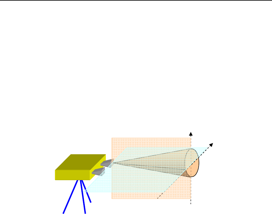
IDS Ingegneria Dei Sistemi S.p.A. N°doc: MN/2009/070 - Rev. 1.1
IBIS-L v.02.00 - User manual
64 / 65
All information contained in this document is property of IDS. All rights reserved.
Appendix B - ELEMENTS OF RADAR TECHNOLOGY
B.1 Antenna beam
The term antenna main lobe (or beam) is intended as the angular area within which the
antenna concentrates most of the power it is supplied with.
The main lobe of an antenna can be schematically represented as a truncated cone with an
elliptic base, where the cone vertex is positioned in correspondence with the antenna. The
base of the cone is elliptical since antennas typically have lobes with different angular
amplitudes in the elevation (V) and azimuth (H) planes.
Fig. B. 1 – Schematic diagram of the antenna beam
The following parameters are normally defined to quantify the antenna beam amplitude:
• The beam at -3dB: angular area within which antenna gain is more than 50% of the
maximum gain (-3 dB = 10*log10(0,5)).
• The beam at -10 by: angular area within which gain is more than 10% of the
maximum gain (-10 dB = 10* log10(0,1)).
From an applicative point of view, this means that the sensor must be pointed so that the
scenario of interest falls inside the antenna beam, preferably at -3dB. Therefore the
distance at which the instrument should be positioned and its inclination should be chosen
as a function of the antenna beam being used.
V plane
H plane
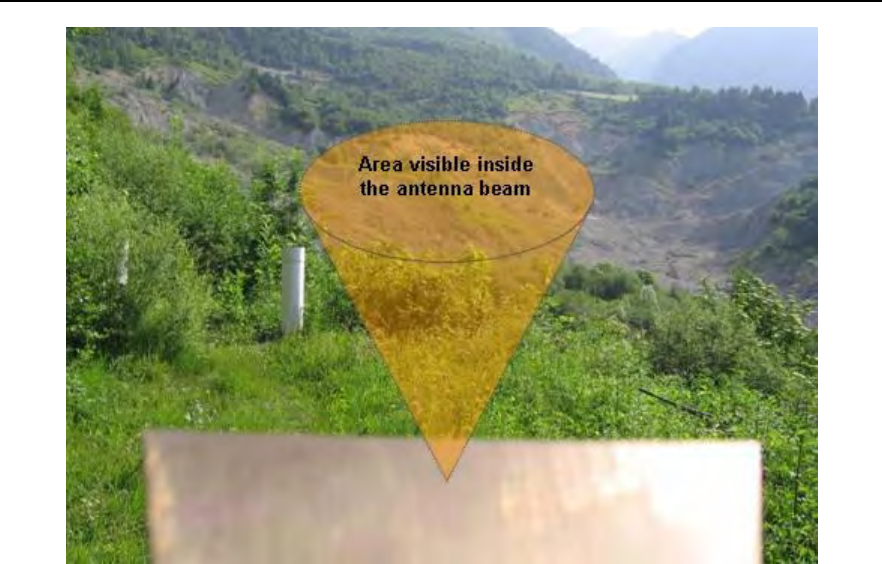
IDS Ingegneria Dei Sistemi S.p.A. N°doc: MN/2009/070 - Rev. 1.1
IBIS-L v.02.00 - User manual
65 / 65
All information contained in this document is property of IDS. All rights reserved.
Fig. B. 2 – Area of the scenario covered by the antenna beam main lobe.