IDS GeoRadar s r l SRS-FW400 Ground Penetrating Radar User Manual MN 2009 030 12 SRSPLUS ENG VALTER france finale
IDS Ingegneria dei Sistemi SpA Ground Penetrating Radar MN 2009 030 12 SRSPLUS ENG VALTER france finale
UserManual.wiki
>
IDS GeoRadar s r l
>
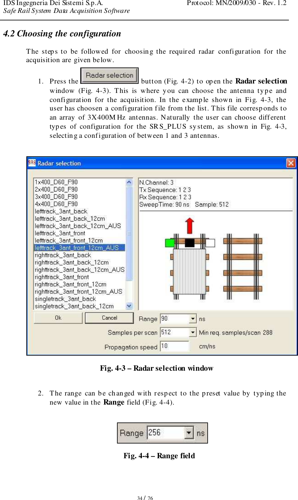
SRS FW400 User Manual
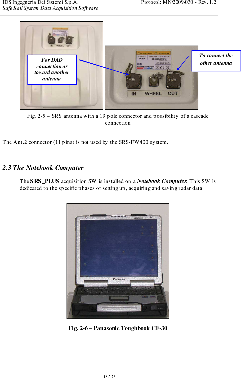
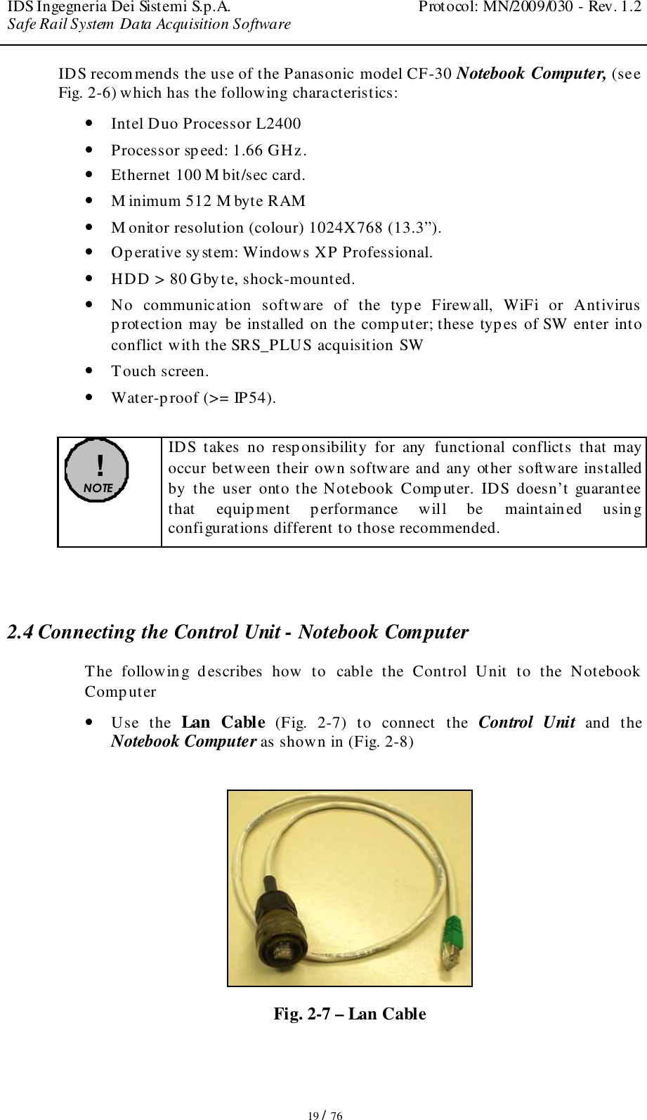
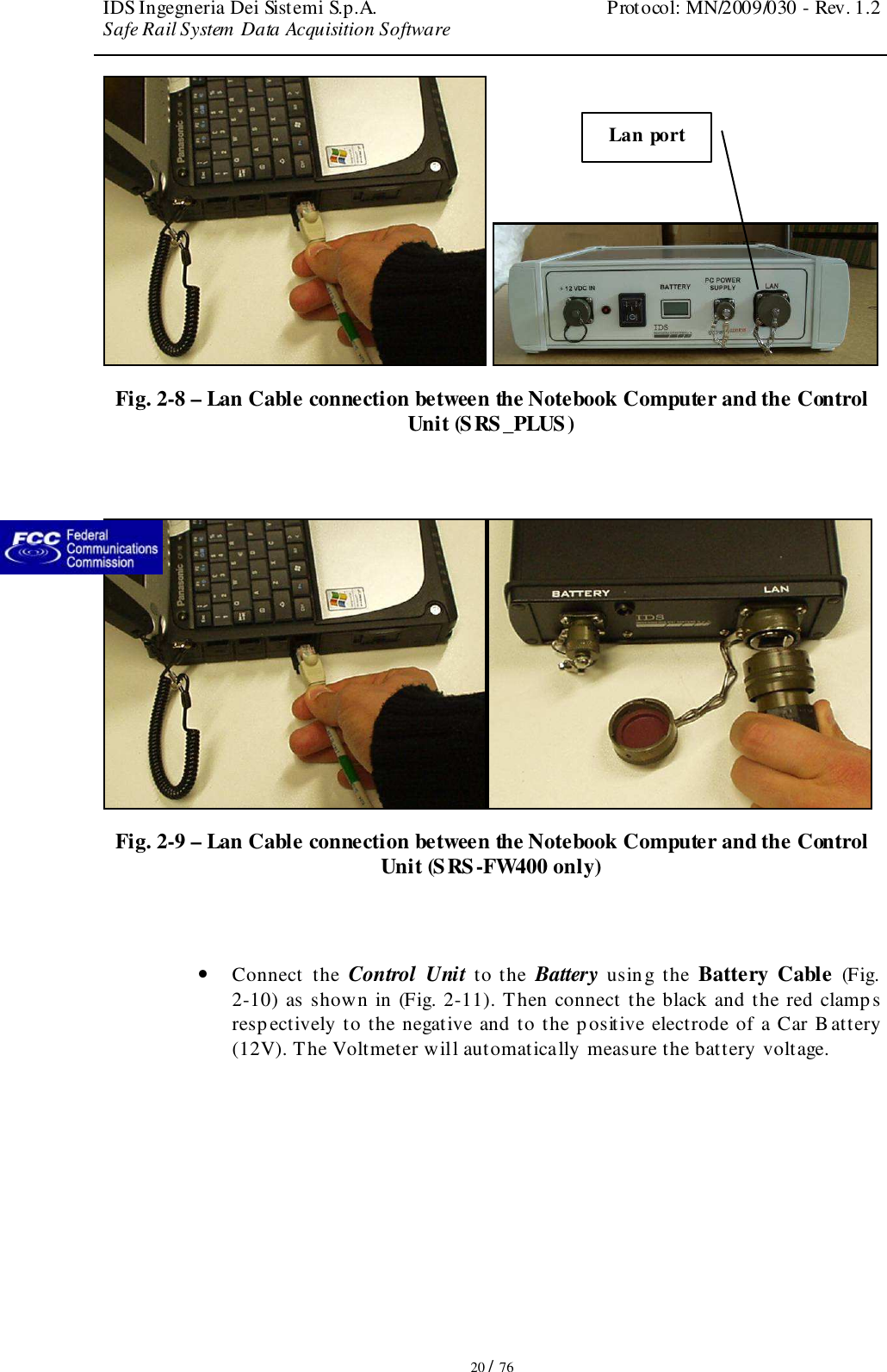
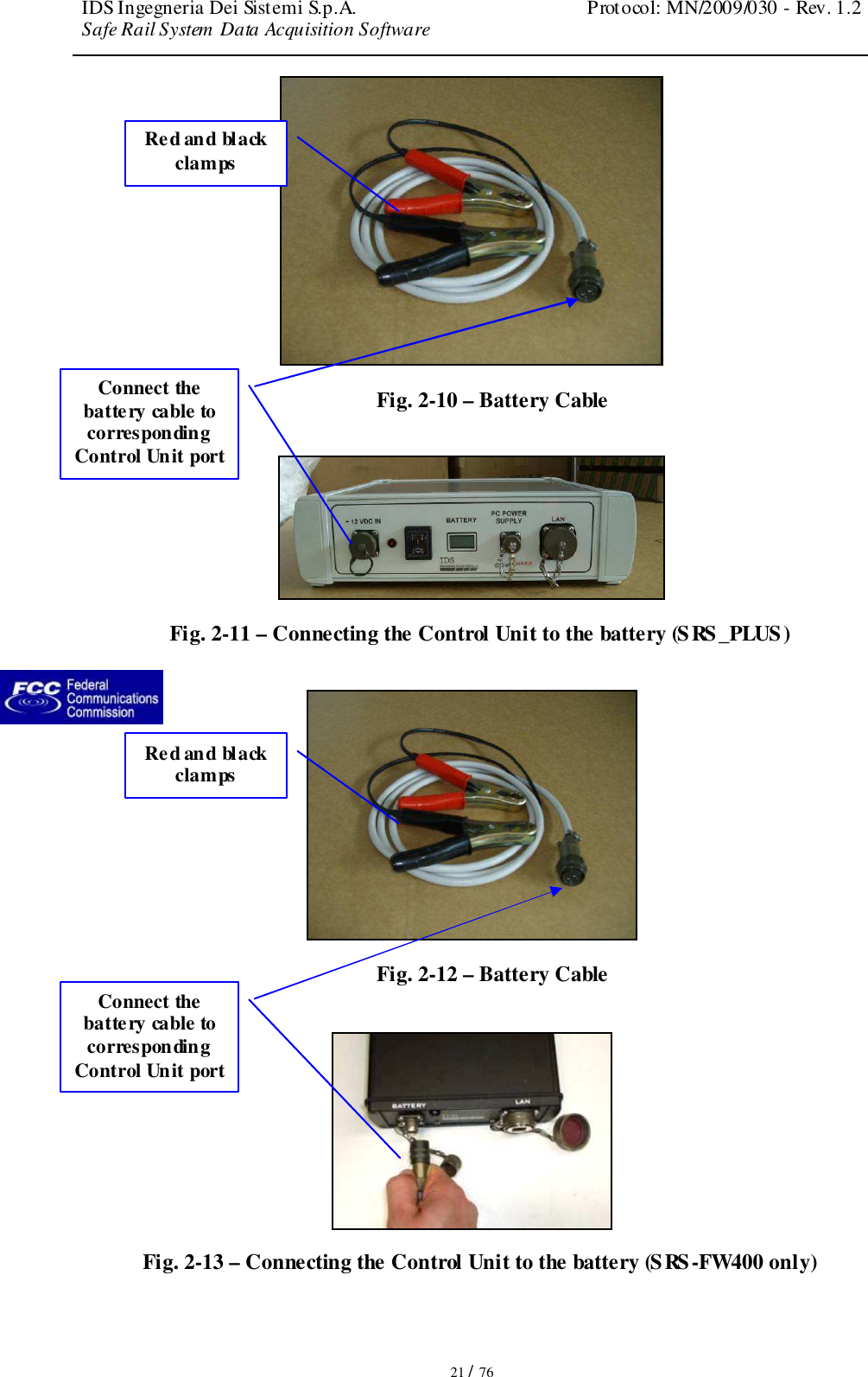
SRS-FW400 user manual
Navigation menu
Upload a User Manual
Namespaces
Wiki Guide
HTML
PDF
Info
Views
User Manual
Discussion / Help
Navigation