IDS GeoRadar s r l SRS-FW400 Ground Penetrating Radar User Manual MN 2009 030 12 SRSPLUS ENG VALTER france finale
IDS Ingegneria dei Sistemi SpA Ground Penetrating Radar MN 2009 030 12 SRSPLUS ENG VALTER france finale
SRS-FW400 user manual
INGEGNERIA DEI SISTEMI S.p.A.
Rev. 1.2
Protocol: MN/2009/030
Safe Rail System User Guide
Signature Date
Compiled by
Valter Baroncini
Controlled by
Stefania Bracciali
Approved by
Laura Della Maggiore
Authorised by
Guido Manacorda
August 2009
IDS Ingegneria Dei Sistemi S.p.A. Protocol: MN/2009/030 - Rev. 1.2
Safe Rail System Data Acquisition Software
2
/
76
Document Evolution
Revision Date Reason for modification
Rev. 1.0 March 2009 First edition
Rev. 1.1 July 2009 Add of Mechanical kit
Rev 1.2 August 2009 FCC information added
SW Versions covered by this document
01.03.001, 01.06.001, 01.07.006, 01.07.007.
OUR CONTACTS
IDS Ingegneria dei Sistemi S.p.A. – GeoRadar Division
Via Sterpulino, 20
56121 Ospedaletto (PISA) - ITALIA
Tel: +39.050.967111
Fax: +39.050.967121
inforis@ids-spa.it
Customer Care department:
customercare.gpr@ids-spa.it
Tel.: +39.050.967122
Sales & Marketing department:
sales.gpr@ids-spa.it
Tel.: +39.050.967123/24/43
IDS Ingegneria Dei Sistemi S.p.A. Protocol: MN/2009/030 - Rev. 1.2
Safe Rail System Data Acquisition Software
3
/
76
DISCLAIMER
IDS WILL NOT BE HELD RESPONSIBLE FOR THE
CONSEQUENCES OF AN
IMPROPER USE OF THE EQUIPMENT AND/OR THE SOFTWARE.
THIS SOFTWARE MAY INCLUDE AUTOMATED DATA
PROCESSING AND
ANALYSIS TOOLS.
WHILE EVERY EFFORT IS MADE TO ENSURE THE ACCURACY OF THE
INFORMATION PROVIDED BY THOSE TOOLS, THE
Y MUST NOT BE
INTENDED AS A SUBSTITUTE FOR INTELLIGENT ANALYSIS; RATHER, T
HEY
HAVE TO BE INTENDED AS AN ADVISOR AND TH
E USER MUST NOT
COMPLETELY RELY ON THE RESULTS PROVIDED
BY THEM TO GIVE THE
COMPLETE ANSWER.
IDS INGEGNERIA DEI SISTEMI SPA ASSUMES NO LIABILITY FOR ANY
DIRECT, INDIRECT, SPECIAL, INCIDENTAL OR CONSEQUENTIAL DAMAGES
OR INJURIES CAUSED BY SUCH RELIANCE ON THE ACCURACY,
RELIABILITY, OR TIMELESS OF THE INFORMATION PROVIDED BY THOSE
TOOLS.
ANY PERSON OR ENTITY WHO RELIES ON INFORMATION OBTAINED FROM
THE AUTOMATED DATA PROCESSING/ANALYSIS TOOLS ONLY, DOES SO AT
HIS OR HER OWN RISK
IDS Ingegneria Dei Sistemi S.p.A. Protocol: MN/2009/030 - Rev. 1.2
Safe Rail System Data Acquisition Software
4
/
76
SAFETY INFORMATION
The equipment conforms to the following requirements set by EC
regulations, incl
uding subsequent modifications, and to the legislation set
by the member states that implement these regulations:
1999/05/EEC Radio Directive
Warning: this equipment is destined for use in industrial environments
(Class A apparatus). In residential, comme
rcial and light industry
environments, this apparatus may generate radio interference: in this case,
the user may be required to operate while taking appropriate
countermeasures.
The apparatus is sensitive to the presence of external electromagnetic fields
,
which may reduce its performance.

IDS Ingegneria Dei Sistemi S.p.A. Protocol: MN/2009/030 - Rev. 1.2
Safe Rail System Data Acquisition Software
5
/
76
IMPORTANT NOTE FOR THE US CUSTOMERS
FCC ID: UFW-SRS-FW400
This device complies with part 15 of the FCC Rules:
Operation is subject to the following conditions:
1. This device may not cause harmful interference, and
2. This device must accept any interference received, Including interference that may cause undesired operation
Warning: Changes or modifications to this unit not expressly approved by the party
responsible for compliance could void the user’s authority to operate the equipment.
Operation of this device is restricted to law enforcement, fire and rescue officials, scientific research institutes,
commercial mining companies, and construction companies. Operation by any other party is a violation of 47 U.S.C. §
301 and could subject the operator to serious legal penalties.
Coordination Requirements
(a) UWB imaging systems require coordination through the FCC before the equipment may be used. The operator shall
comply with any constraints on equipment usage resulting from this coordination.
(b) The users of UWB imaging devices shall supply detailed operational areas to the FCC Office of Engineering and
Technology who shall coordinate this information with the Federal Government through the National
Telecommunications and Information Administration. The information provided by the UWB operator shall include the
name, address and other pertinent contact information of the user, the desired geographical area of operation, and the
FCC ID number and other nomenclature of the UWB device. This material shall be submitted to the following address:
Frequency Coordination Branch., OET
Federal Communications Commission
445 12th Street, SW
Washington, D.C. 20554
ATTN: UWB Coordination
(d) Users of authorized, coordinated UWB systems may transfer them to other qualified users and to different locations
upon coordination of change of ownership or location to the FCC and coordination with existing authorized operations.
(e) The NTIA/FCC coordination report shall include any needed constraints that apply to day-to-day operations. Such
constraints could specify prohibited areas of operations or areas located near authorized radio stations for which
additional coordination is required before operation of the UWB equipment. If additional local coordination is required,
a local coordination contact will be provided.
(f) The coordination of routine UWB operations shall not take longer than 15 business days from the receipt of the
coordination request by NTIA. Special temporary operations may be handled with an expedited turn-around time when
circumstances warrant. The operation of UWB systems in emergency situations involving the safety of life or property
may occur without coordination provided a notification procedure, similar to that contained in CFR47 Section 2.405(a)-
(e), is followed by the UWB equipment user.
Notice: Use of this device as a wall imaging system is prohibited by FCC regulations.
In this manual, instructions that specifically apply to the version of the system
dedicated to the US market, are identified by the following label

IDS Ingegneria Dei Sistemi S.p.A. Protocol: MN/2009/030 - Rev. 1.2
Safe Rail System Data Acquisition Software
6
/
76
!
WARNING
CLEANING INFORMATION
Before cleaning any external parts of the apparatus, make sure
that all cables have been disconnected, including the power
supply cable.
If a damp cloth is used, make sure it is not too wet,
to avoid any damage to the electrical components of the
equipment. Wait until the equipment is totally dry before
reconnecting the cables.
The Detector Duo should be cleaned periodically using a damp
cloth.
Do not use solvents or abrasive detergents.
Do not apply liquid directly to the electrical contacts of the
various connectors. If a specific spray is used to clean the PC
TFT monitor, make sure it is not flammable; ion any case, do not
spray it direct
ly on the screen, instead, spray it onto the cleaning
cloth.
IDS Ingegneria Dei Sistemi S.p.A. Protocol: MN/2009/030 - Rev. 1.2
Safe Rail System Data Acquisition Software
7
/
76
BATTERIES REMOVAL INFORMATION
Laptop Batteries:
Manufacturer: PANASONIC
Type: Li-ion Ni
Characteristics: 10.65V 5.7Ah
Removal instructions:
1. turn off the laptop;
2. open the drawer with the symbol of the batteries;
3. extract the battery pack pulling the tab.
Radar batteries:
Manufacturer: FIAMM FG21202 / SAFT MP176065
Type: rechargeable lead acid / rechargeable lithium-ion
Characteristics: 12V & 12Ah / 15V & 6.8Ah
Removal instructions:
1. disconnect the battery from the instrument:
a. pull the connector wings;
b. separate the connectors;
2. remove the battery from the cover (optional) opening the
strap.

IDS Ingegneria Dei Sistemi S.p.A. Protocol: MN/2009/030 - Rev. 1.2
Safe Rail System Data Acquisition Software
8
/
76
RECICLYING
The crossed out wheeled bin symbol shown on the equipment indicates that
the product must be recycled separately from other waste at the end of its
useful life.
Separate waste disposal of this product at the end of its useful life will be
organised and managed by IDS. When you decide to dispose of the
equipment, contact IDS and follow the system that IDS has set up to permit
the separate collection of the apparatus at its life end.
Adequate separate collection for its subsequent recycling, treatment and
environmental friendly disposal contribute towards avoiding any
unnecessary effects on the environment and to health and favour the reuse or
recycling of the materials that make up the equipment. Unauthorised disposal
of this product as unsorted waste by its possessor will lead to an
administrative penalty foreseen by national regulations.

IDS Ingegneria Dei Sistemi S.p.A. Protocol: MN/2009/030 - Rev. 1.2
Safe Rail System Data Acquisition Software
9
/
76
WARRANTY CERTIFICATE CONDITIONS
1) IDS Ingegneria dei Sistemi S.p.A, hereinafter referred to as IDS, warrants hardware/software
products for a period of 12 months from the delivery date to the original customer;
2) The delivery date is certified by the “ Warranty Registration Form”;
3) IDS’s hardware products will be free from defects in materials workmanship under normal use
and service;
4) IDS’s obligation is limited to repairing or replacing parts or equipment which are returned to IDS,
without alteration or further damage, and which in IDS s judgment, were defective or became
defective during normal use;
5) IDS’ software will have to be installed on a PC according to the requirement of the IDS hardware
( see IDS User’s Guide the Software Data Acquisition);
6) IDS’ s software products designed by IDS for use for IDS hardware products are warranted not to
fail to execute their programming instructions due to defects during the warranty period, provided
they are properly installed on IDS hardware products. IDS does not warrant if the IDS software will
be used and operated in hardware and software combinations not selected by IDS;
7) IDS does not assumes any liability for any direct, indirect, special, incidental or consequential
damages or injuries caused by proper or improper operation of its equipment whether defective or
not defective;
8) This software may include automated data processing and analysis tools. While every effort is
made to ensure the accuracy of the information provided by those tools, they must not be intended
as a substitute for intelligent analysis; rather, they have to be intended as an advisor and the user
must not completely rely on the results provided by them to give the complete answer. IDS assumes
no liability for any direct, indirect special, incidental or consequential damages or injuries caused by
such reliance on the accuracy, reliability, or timeliness of the information provided by those tools.
Any person or entity who relies on information obtained from the automated data
processing/analysis tools only, does so at his or her own risk;
9) IDS’s warranty does not extend and shall not apply to:
a) Products which have been repaired or altered by other than IDS personnel;
b) Products which have been subjected to misuse, neglect, accident or improper installation;
c) Products in which have been installed Hardware/Software accessories not supplied by IDS
and/or without any approval by IDS;
d) Products which have been connected to equipment different from the ones supplied by IDS
(except the PC data Logger which must conform to IDS specifications;
e) Products which have been damaged by natural disaster or calamities.
10) Before returning any equipment to IDS , you have to contact the IDS Customer Care Office that
will authorize you to return the material to be repaired;
11) Once the parts/equipment to be repaired arrive to IDS, IDS may inspect the defective products to
verify they are eligible for repair or replacement. All packing must be saved for inspection purpose
in order to assist IDS to understand the cause of the defects. IDS, will not be obliged to repair, or
replace for products returned as defective but damaged from abuse, misuse, neglicence , accident
loss or damage in transit;
12) The final clients, is responsible for ensuring the defective products returned to be properly
packaged;
13) The above warranty are sole and exclusive, and no other warranty, whether written or oral, is
expressed or implied.

IDS Ingegneria Dei Sistemi S.p.A. Protocol: MN/2009/030 - Rev. 1.2
Safe Rail System Data Acquisition Software
10
/
76
INDEX
1. Overview.....................................................................................................................14
1.1 How to use this manual.......................................................................................14
2. The SRS System Hardware configuration..............................................................15
2.1 The SRS_PLUS Control Unit..............................................................................15
2.2 The SRS-FW400 Control Unit ............................................................................16
2.3 The Notebook Computer.....................................................................................18
2.4 Connecting the Control Unit - Notebook Computer...........................................19
2.5 Position radar sensor .........................................................................................22
2.6 Antennas .............................................................................................................24
2.7 Mechanical kit ....................................................................................................25
3. Software configuration of the SRS system..............................................................28
3.1 Software Installation and configuration .............................................................28
4. SRS acquisition software...........................................................................................33
4.1 Starting the SRS_PLUS acquisition software.....................................................33
4.2 Choosing the configuration ................................................................................34
4.3 Setting up the Calibration...................................................................................35
4.3.1 Advanced Settings Menu...........................................................................42
4.4 Choosing a survey...............................................................................................44
4.5 Setting the acquisition parameters .....................................................................46
4.6 Data acquisition..................................................................................................51
4.7 Operating in review mode ..................................................................................55
5. Error messages and alarms.......................................................................................58
5.1 Error messages...................................................................................................58
6. On line assistance.......................................................................................................59
6.1 Remote assistance using Webex Support Center ................................................59
6.1.1 How to use the Webex service....................................................................59
Appendix A - Mechanical Requirements for the installation of SRS
SYSTEMS on board a train..........................................................................................62
A.1 - Introduction......................................................................................................62
A.2 - Mechanical requirements.................................................................................62
A.3 - Specifications for the fixing frame...................................................................64
Appendix B - SRS System technical specifications....................................................66
B.1 - SRS_PLUS System Technical Specifications ...................................................66

IDS Ingegneria Dei Sistemi S.p.A. Protocol: MN/2009/030 - Rev. 1.2
Safe Rail System Data Acquisition Software
11
/
76
B.1.1 SRS_PLUS Control Unit specifications......................................................66
B.2 - SRS-FW400 System Technical Specifications..................................................67
B.2.1 Control Unit specifications........................................................................67
Appendix C - Using GPS with the SRS system...........................................................68
Appendix D - Using camera with the SRS system......................................................72
FIGURES INDEX
FIG. 2-1 – VIEW OF CONTROL UNIT, START UP SIDE............................................15
FIG. 2-2 – VIEW OF CONTROL UNIT, ANTENNA CONNECTORS SIDE................16
FIG. 2-3 – SRS-FW400 CONTROL UNIT FRONT PANEL WITH BATTERY PORT,
LAN PORT AND WIRELESS CONNECTOR........................................................17
FIG. 2-4-SRS-FW400 CONTROL UNIT REAR PANEL WITH CONNECTIONS TO
POSITION SENSOR AND ANTENNAS.................................................................17
FIG. 2-5 – SRS ANTENNA WITH A 19 POLE CONNECTOR AND POSSIBILITY OF
A CASCADE CONNECTION..................................................................................18
FIG. 2-6 – PANASONIC TOUGHBOOK CF-30.............................................................18
FIG. 2-7 – LAN CABLE...................................................................................................19
FIG. 2-8 – LAN CABLE CONNECTION BETWEEN THE NOTEBOOK COMPUTER
AND THE CONTROL UNIT (SRS_PLUS).............................................................20
FIG. 2-9 – LAN CABLE CONNECTION BETWEEN THE NOTEBOOK COMPUTER
AND THE CONTROL UNIT (SRS-FW400 ONLY) ...............................................20
FIG. 2-10 – BATTERY CABLE.......................................................................................21
FIG. 2-11 – CONNECTING THE CONTROL UNIT TO THE BATTERY (SRS_PLUS)
...................................................................................................................................21
FIG. 2-12 – BATTERY CABLE.......................................................................................21
FIG. 2-13 – CONNECTING THE CONTROL UNIT TO THE BATTERY (SRS-FW400
ONLY).......................................................................................................................21
FIG. 2-14 – POWER SUPPLY CABLE AND CONNECTION TO THE CONTROL
UNIT..........................................................................................................................22
FIG. 2-15 – POSITION SENSOR.....................................................................................22
FIG. 2-16 – WHEEL PORT ON THE SRS_PLUS CONTROL UNIT ............................23
FIG. 2-17 – WHEEL PORT ON THE SRS-FW400 CONTROL UNIT...........................23
FIG. 2-18 – 400M HZ SRS_PLUS ANTENNA (TOP), SKETCH OF DRAG
DIRECTION (MIDDLE) AND PVC “H” PLATE (BOTTOM )...............................24
FIG. 2-19 –ANTENNA FOR THE SRS-FW400 SYSTEM (RED ARROWS SHOW
DRAGGING DIRECTION)......................................................................................25
FIG. 2-20 – ANTENNA “L” SUPPORTS AND BAR......................................................26
FIG. 2-21 – DOPPLER SUPPORTS.................................................................................26
FIG. 2-22 – SKETCH OF SRS LAYOUT ........................................................................27
FIG. 3-1 – SW SRS_PLUS INSTALLATION KIT..........................................................28

IDS Ingegneria Dei Sistemi S.p.A. Protocol: MN/2009/030 - Rev. 1.2
Safe Rail System Data Acquisition Software
12
/
76
FIG. 3-2 – INSTALLATION KIT, NEXT BUTTON.......................................................28
FIG. 3-3 – INSTALLATION KIT, TYPICAL BUTTON.................................................29
FIG. 3-4 - INSTALLATION KIT, INSTALL BUTTON..................................................29
FIG. 3-5 – INSTALLATION KIT, FINISH BUTTON.....................................................30
FIG. 3-6 – SELECTING THE INTERNET PROTOCOL (TCP/IP).................................32
FIG. 3-7 – M ODIFYING THE IP CODE .........................................................................32
FIG. 4-1 – ACQUISITION SOFTWARE ICON ..............................................................33
FIG. 4-2 – SRS_PLUS ACQUISITION SOFTWARE STARTUP WINDOW................33
FIG. 4-3 – RADAR SELECTION WINDOW..................................................................34
FIG. 4-4 – RANGE FIELD ...............................................................................................34
FIG. 4-5 – SAM PLES PER SCAN....................................................................................35
FIG. 4-6 – PROPAGATION SPEED FIELD....................................................................35
FIG. 4-7 – GAIN CALIBRATION UNDERWAY...........................................................36
FIG. 4-8 – CONTROLLING THE PRESENCE OF RADAR SIGNAL ON THE
ANTENNA/S.............................................................................................................36
FIG. 4-9 –CALIBRATION FILE SELECTION WINDOW.............................................37
FIG. 4-10 – GAIN WINDOW...........................................................................................37
FIG. 4-11 – GAIN PARAM ETER SETTINGS WINDOW..............................................38
FIG. 4-12 – GRAPHICAL CONSTRUCTION OF THE GAIN CURVE ........................39
FIG. 4-13 – M ANUAL CONSTRUCTION OF THE GAIN CURVE..............................39
FIG. 4-14 – THE SYSTEM FUNCTION SPY LIGHTS..................................................40
FIG. 4-15 – INFO BUTTON.............................................................................................40
FIG. 4-16 – INFO WINDOW............................................................................................41
FIG. 4-17 – COLOUR PALETTES AVAILABLE...........................................................41
FIG. 4-18 – PROGRAM SHUT-DOWN WINDOW........................................................42
FIG. 4-19 – ACTIVATING THE ADVANCED SETTINGS M ENU..............................42
FIG. 4-20 –ADVANCED SETTINGS WINDOW............................................................43
FIG. 4-21 – ACQUISITION SELECTION WINDOW ....................................................44
FIG. 4-22 – NEW SURVEY WINDOW...........................................................................45
FIG. 4-23 – THE *.M IS FOLDER DIRECTORY............................................................45
FIG. 4-24 – NEW ACQUISITION TEXT BOX...............................................................45
FIG. 4-25 – SETTING UP A NEW ACQUISITION........................................................46
FIG. 4-26 – THE CASTLE.M IS FOLDER DIRECTORY...............................................46
FIG. 4-27 – NEW ACQUISITION WINDOW.................................................................47
FIG. 4-28 – ACQUISITION PARAM ETERS WINDOW................................................48
FIG. 4-29 – POS. M ARKER BUTTON............................................................................48
FIG. 4-30 – DIAGRAM SHOWING AN EXAM PLE OF HOW TO USE THE
FUNCTION “WITH 1ST M ARKER 1 STEP”.........................................................51
FIG. 4-31 – RADAR SECTION DURING ACQUISITION ............................................52
FIG. 4-32 – DATA SAVING WINDOW..........................................................................53

IDS Ingegneria Dei Sistemi S.p.A. Protocol: MN/2009/030 - Rev. 1.2
Safe Rail System Data Acquisition Software
13
/
76
FIG. 4-33 – ACQUISITION WINDOW ACTIVATED FOR PERFORMING
OPERATIONS IN REVIEW M ODE........................................................................54
FIG. 4-34 – ACQUISITION EDITING WINDOW..........................................................56
FIG. 4-35 – WINDOW FOR EDITING PARAM ETERS AFTER ACQUISITION
TRANSVERSAL.......................................................................................................56
FIG. 4-36 – SCANS FROM THE SAM E ACQUISITION...............................................56
FIG. 4-37 – RENAM E ACQUISITION WINDOW.........................................................57
FIG. 4-38 – DELETE ACQUISITION WINDOW...........................................................57
FIG. 6-1 – M AIL SENT BY IDS TO THE CLIENT........................................................59
FIG. 6-2 – CLIENT DATA INSERTION FORM.............................................................60
FIG. 6-3 – WEBEX SET UP WINDOW...........................................................................60
FIG. 6-4 – WELCOM E TO WEBEX SUPPORT CENTER WINDOW..........................61
FIG. 6-5 – COMMAND ACCEPTANCE WINDOW ......................................................61
FIG. A. 1 - NO OBSTACLE M UST BE PRESENT BETWEEN BUFFERS ..................63
FIG. A. 2 - EXAMPLE OF A TYPICAL INSTALLATION OF THE SYSTEM ............63
FIG. A. 3 - OVERVIEW OF THE FIXING FRAM E.......................................................64
FIG. A. 4 - SPECIFICATIONS FOR THE CROSS-BARS AND THE BRACKETS......65
FIG. A. 5 - SPECIFICATIONS FOR THE VERTICAL-BARS.......................................65
FIG. B. 1 – SRS_PLUS CONTROL UNIT AND CF-30 NOTEBOOK...........................66
FIG. C. 1 - CONNECTING THE GPS TO THE NOTEBOOK COMPUTER.................68
FIG. C. 2 - EXTERNAL DEVICE SETTINGS COMMAND..........................................68
FIG. C. 3 - EXTERNAL DEVICE SETTINGS WINDOW..............................................69
FIG. C. 4 - EXTERNAL DEVICE SETTINGS FIELD....................................................69
FIG. C. 5 - COM SETTINGS WINDOW.........................................................................70
FIG. C. 6 - GPS SPY .........................................................................................................70
FIG. C. 7 - EXAMPLE OF A GPS FILE ..........................................................................71
FIG. D. 1 – VIDEOCAM ERA “LUM ENERA LM 135C”................................................72
FIG. D. 2 - EXTERNAL DEVICE SETTINGS COMM AND..........................................73
FIG. D. 3 - EXTERNAL DEVICE SETTINGS WINDOW .............................................73
FIG. D. 4 – CAM ERA PROPERTIES ..............................................................................74
FIG. D. 5 – CAM ERA VIEW WINDOW.........................................................................75
FIG. D. 6 – FOLDER “CAM ERA”...................................................................................75

IDS Ingegneria Dei Sistemi S.p.A. Protocol: MN/2009/030 - Rev. 1.2
Safe Rail System Data Acquisition Software
14
/
76
1. OVERVIEW
1.1 How to use this manual
This SRS_PLUS software user manual is subdivided as follows:
•
Chap. 1: Overview.
•
Chap. 2: Hardware configuration of the SR S_PLUS and of the SRS-
FW400 systems
•
Chap. 3: SRS_PLUS/SR S-FW400 acquisition software op erating
procedures.
•
Chap. 4: Setup of the SRS_PLUS/SRS-FW400 acquisition software
•
Chap. 5: Error messages and warnings
•
Chap. 6: On Line Assistance
IDS Ingegneria Dei Sistemi S.p.A. Protocol: MN/2009/030 - Rev. 1.2
Safe Rail System Data Acquisition Software
15
/
76
2. THE SRS SYSTEM HARDWARE CONFIGURATION
The SRS system consists of the following parts:
• SRS_PLUS or SRS-FW400 Control Unit
• Notebook Computer
• Lan Cable
• Battery Cable
• Battery Pack
• Power supply cable
• Position sensor
• From one to four 400MHz antennas
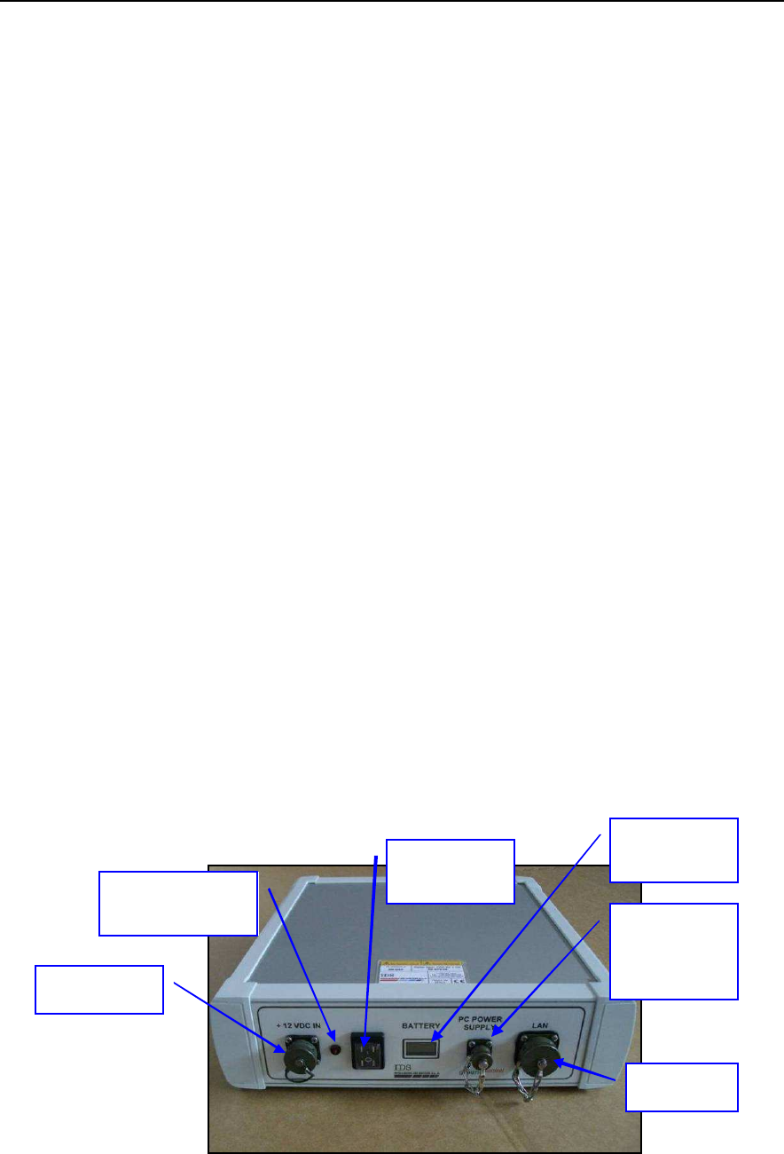
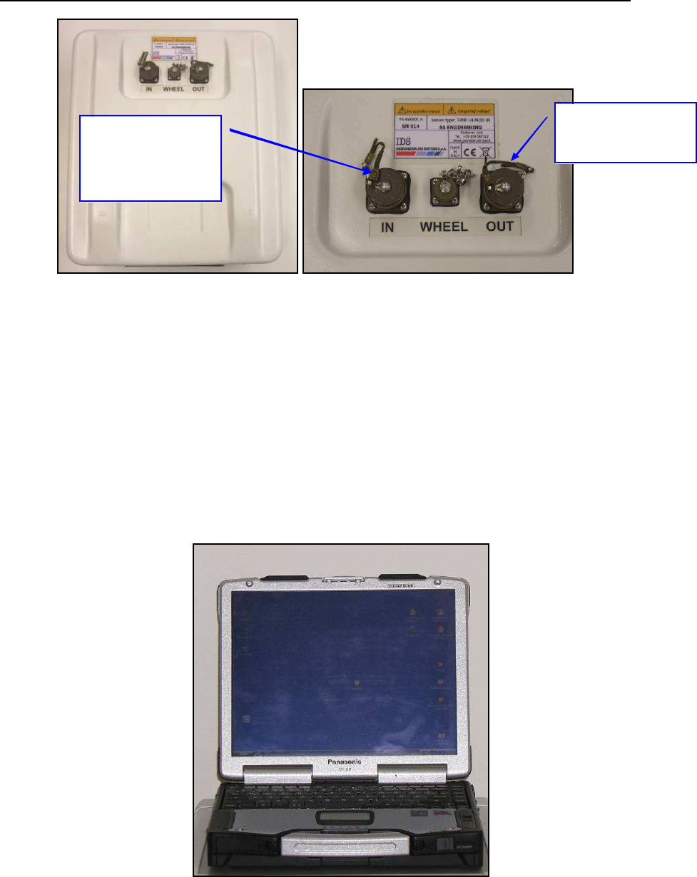
2.1 The SRS_PLUS Control Unit
The
SRS_PLUS Control Unit
is the control unit responsible for directing the
antennas and digitalising the acquired radar data and it has the following ports:
• Lan Port
for a network connection to the Notebook Computer
• Battery Port
to connect the battery
• Wheel Port
to connect the position sensor wheel
• Ant. 1 - Ant. 2 – Ant. 3 – Ant. 4
for the connections to the radar antennas
• Start up button and indicator light
• Voltmeter
• Notebook connection port
Fig. 2-1 – View of Control Unit, start up side
LAN port
Battery Port
Start up
button
Switched on
indicator light
Battery
Voltmeter
Notebook
connection
port
IDS Ingegneria Dei Sistemi S.p.A. Protocol: MN/2009/030 - Rev. 1.2
Safe Rail System Data Acquisition Software
16
/
76
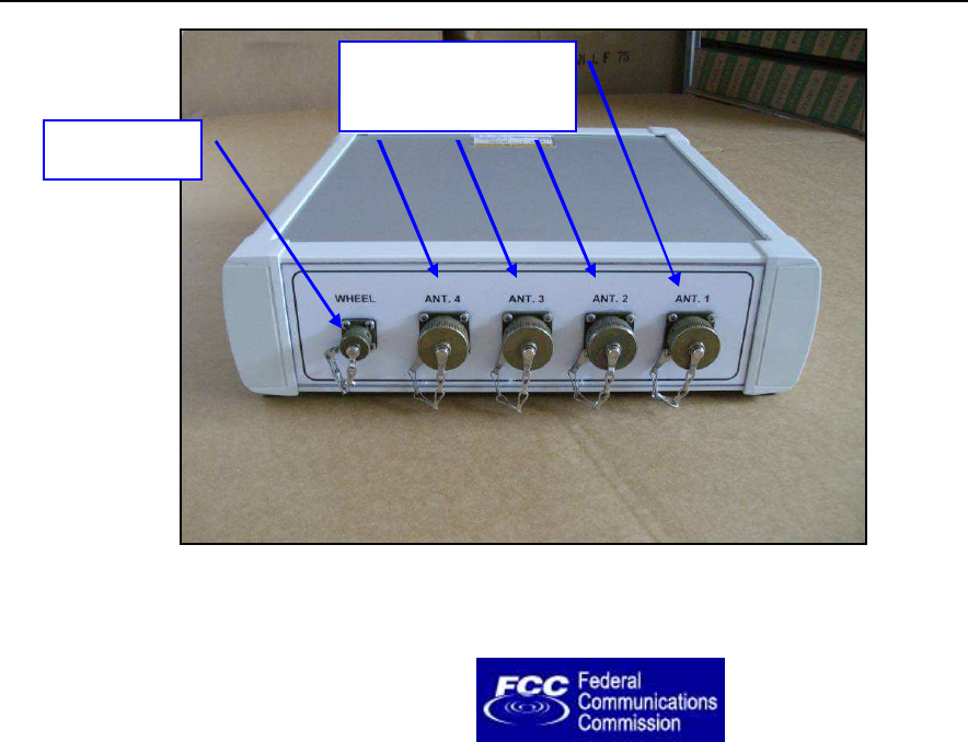
Fig. 2-2 – View of Control Unit, antenna connectors side
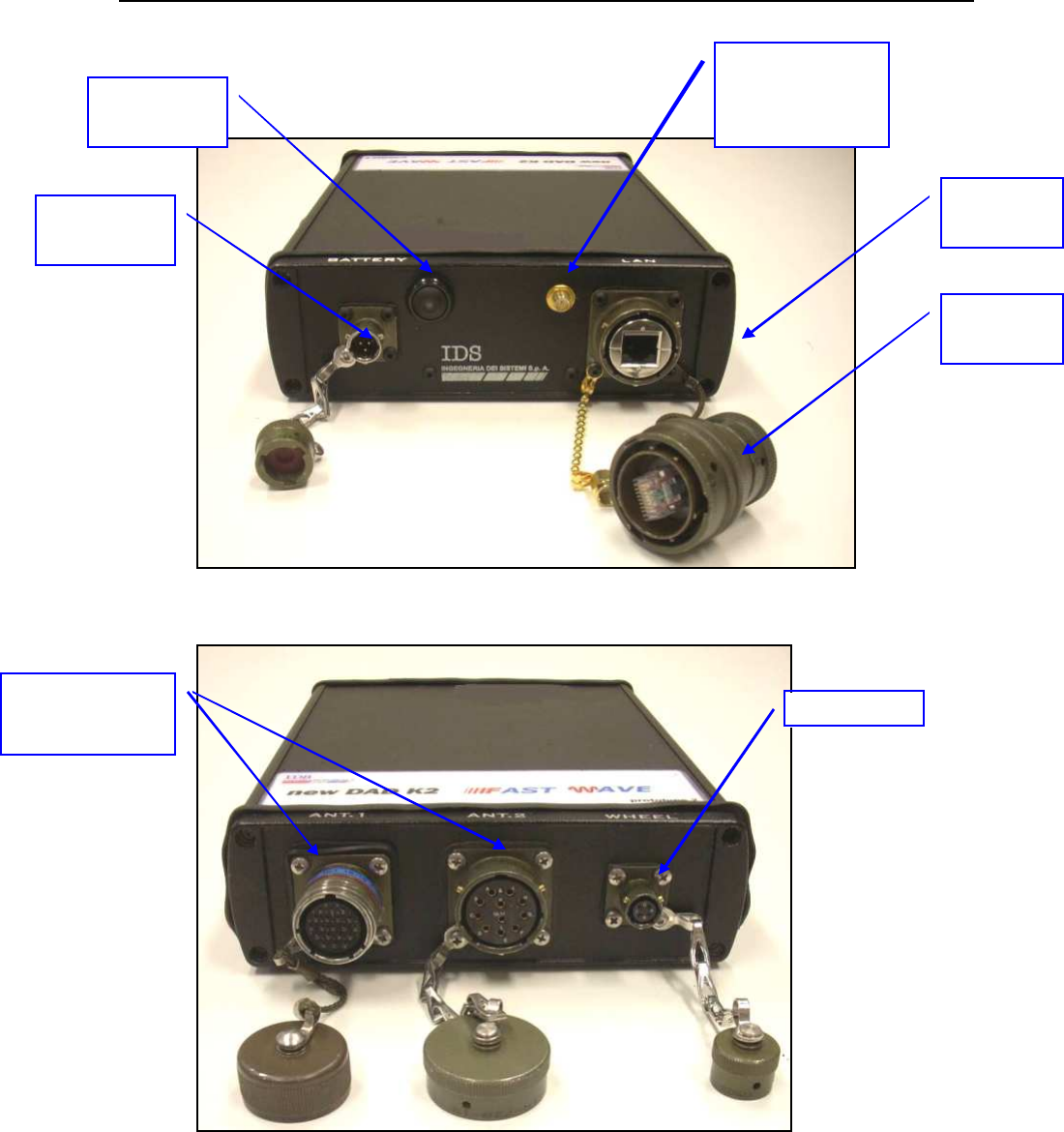
2.2 The SRS-FW400 Control Unit
The
SRS-FW400 Control Unit
has the following ports
• Lan Port
for a network connection to the Notebook Computer
• Battery Port
to connect the battery
• Wheel Port
to connect the position sensor wheel
• Ant.1/CHAIN - Ant.2
for radar antenna conn ection
• Power switch with pilot light
• Wireless antenna connector
Antenna 1, 2, 3, 4
Connectors
Wheel Port
IDS Ingegneria Dei Sistemi S.p.A. Protocol: MN/2009/030 - Rev. 1.2
Safe Rail System Data Acquisition Software
17
/
76
-
Fig. 2-3 – SRS-FW400 Control unit front panel with Battery Port, Lan Port and
wireless connector
Fig. 2-4-SRS-FW400 Control unit rear panel with connections to position sensor
and antennas
The SRS-FW400 uses the Ant.1 connector only (19 pins connector) to connect the
SRS antennas with a cascade connection.
Ant1 and Ant 2
Connectors
Wheel Port
LAN port
Battery Port
Start up
button
Wireless
antenna
connector
Wireless
plug
IDS Ingegneria Dei Sistemi S.p.A. Protocol: MN/2009/030 - Rev. 1.2
Safe Rail System Data Acquisition Software
18
/
76
Fig. 2-5 – SRS antenna with a 19 pole connector and possibility of a cascade
connection
The Ant.2 connector (11 pins) is not used by the SRS-FW400 sy stem.
2.3 The Notebook Computer
The
SRS_PLUS
acquisition SW is installed on a
Notebook Computer.
This SW is
dedicated to the specific p hases of setting up, acquiring and saving radar data.
Fig. 2-6 – Panasonic Toughbook CF-30
For DAD
connection or
toward another
antenna
To connect the
other antenna
IDS Ingegneria Dei Sistemi S.p.A. Protocol: MN/2009/030 - Rev. 1.2
Safe Rail System Data Acquisition Software
19
/
76
IDS recommends the use of the Panasonic model CF-30
Notebook Computer,
(see
Fig. 2-6) which has the following characteristics:
•
Intel Duo Processor L2400
•
Processor speed: 1.66 GHz.
•
Ethernet 100 M bit/sec card.
•
M inimum 512 M byte RAM
•
M onitor resolution (colour) 1024X768 (13.3”).
•
Operative system: Windows XP Professional.
•
HDD > 80 Gbyte, shock-mounted.
•
No communication software of the type Firewall, WiFi or Antivirus
protection may be installed on the computer; these types of SW enter into
conflict with the SRS_PLUS acquisition SW
•
Touch screen.
•
Water-proof (>= IP54).
!
NOTE
IDS takes no responsibility for any functional conflicts that may
occur between their own software and any other software installed
b
y the user onto the Notebook Computer. IDS doesn’t guarantee
that equipment performance will be maintained using
configurations different to those recommended.
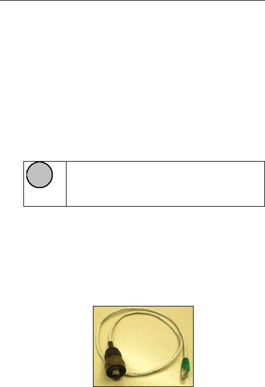
2.4 Connecting the Control Unit - Notebook Computer
The following d escribes how to cable the Control Unit to the Notebook
Computer
•
Use the
Lan Cable
(Fig. 2-7) to connect the
Control Unit
and the
Notebook Computer
as shown in (Fig. 2-8)
Fig. 2-7 – Lan Cable
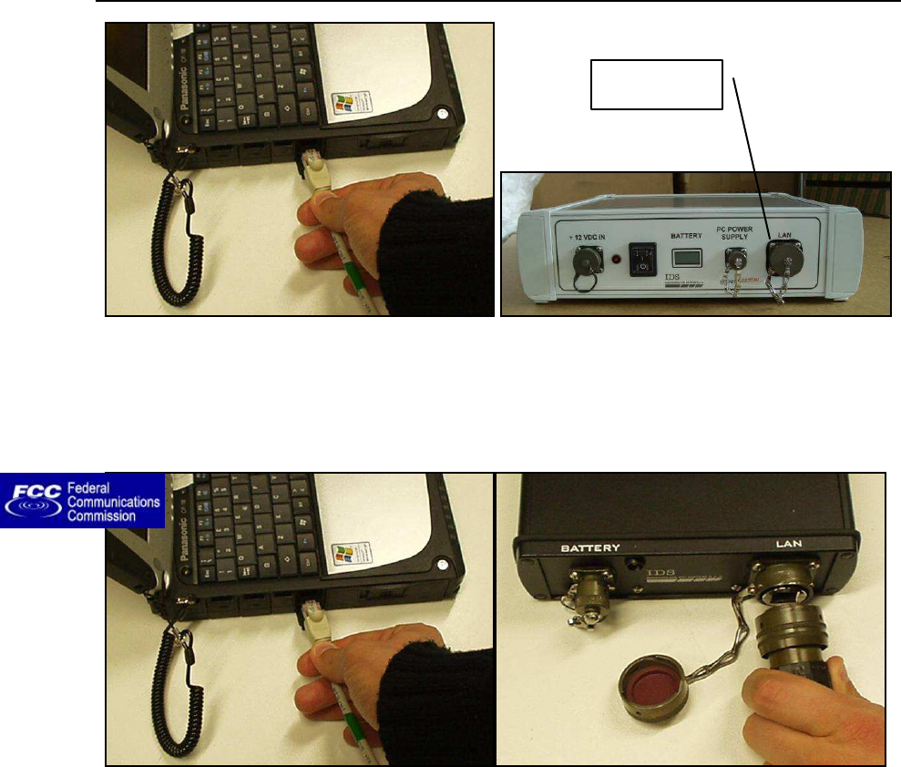
IDS Ingegneria Dei Sistemi S.p.A. Protocol: MN/2009/030 - Rev. 1.2
Safe Rail System Data Acquisition Software
20
/
76
Fig. 2-8 – Lan Cable connection between the Notebook Computer and the Control
Unit (SRS_PLUS)
Fig. 2-9 – Lan Cable connection between the Notebook Computer and the Control
Unit (SRS-FW400 only)
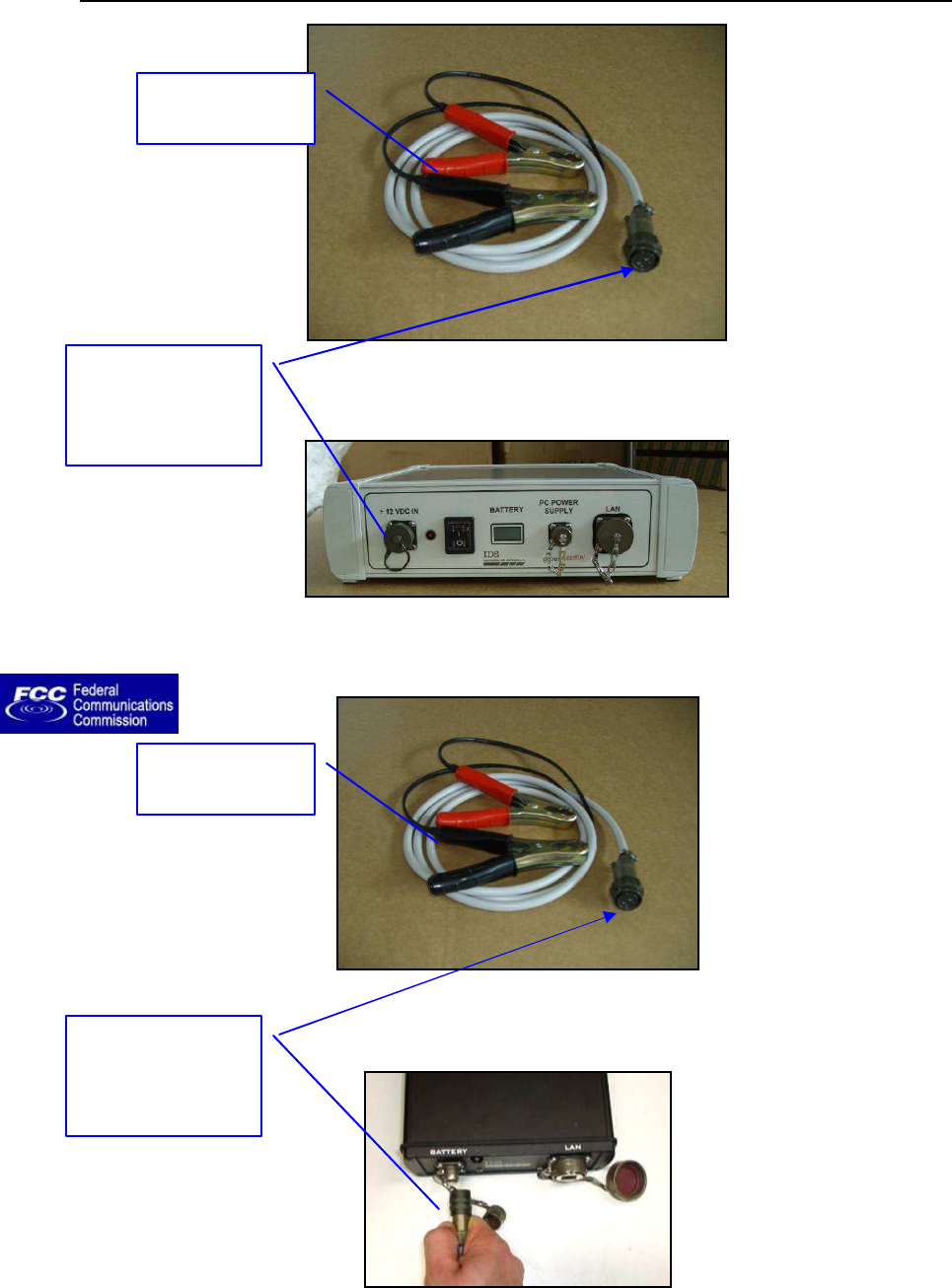
•
Connect the
Control Unit
to the
Battery
using the
Battery Cable
(Fig.
2-10) as shown in (Fig. 2-11). Then connect the black and the red clamps
resp ectively to the negative and to the positive electrode of a Car B attery
(12V). The Voltmeter will automatically measure the battery voltage.
Lan port
IDS Ingegneria Dei Sistemi S.p.A. Protocol: MN/2009/030 - Rev. 1.2
Safe Rail System Data Acquisition Software
21
/
76
Fig. 2-10 – Battery Cable
Fig. 2-11 – Connecting the Control Unit to the battery (SRS_PLUS)
Fig. 2-12 – Battery Cable
Fig. 2-13 – Connecting the Control Unit to the battery (SRS-FW400 only)
Connect the
battery cable to
corresponding
Control Unit port
Red and black
clamps
Connect the
battery cable to
corresponding
Control Unit port
Red and black
clamps
IDS Ingegneria Dei Sistemi S.p.A. Protocol: MN/2009/030 - Rev. 1.2
Safe Rail System Data Acquisition Software
22
/
76
• SRS_PLUS only: Then connect the power supply cable to the PC POWER
SUPPLY port on the Control Unit and to the Notebook PC (see Fig. 2-14).
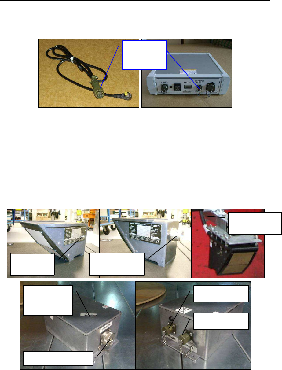
Fig. 2-14 – Power supply cable and connection to the Control Unit
2.5 Position radar sensor
As position sensor we provide a Deuta-Werke DRS05 Doppler system (see Fig. 2-15).
The Doppler system must be connected through its cable to the Doppler interface box
(Doppler port). Then you have to connect the wheel cable from the Doppler interface box
(wheel port) to the DAD CONTROL UNIT wheel port.
Fig. 2-15 – Position sensor
PC Power
Supply
connection
DOPPLER
SYSTEM
CONNECTION
PORT
WHEEL PORT
POWER PORT
DOPPLER
INTERFACE
BOX
CONNECTION
CABLE
DOPPLER PORT
IDS Ingegneria Dei Sistemi S.p.A. Protocol: MN/2009/030 - Rev. 1.2
Safe Rail System Data Acquisition Software
23
/
76
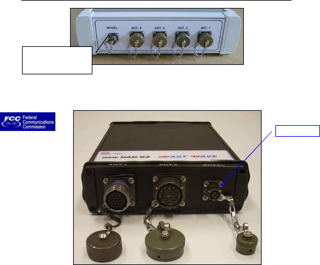
Fig. 2-16 – Wheel port on the SRS_PLUS control unit
Fig. 2-17 – Wheel port on the SRS-FW400 control unit
WHEEL PORT ON
THE DAD
CONTROL UNIT
Wheel Port

IDS Ingegneria Dei Sistemi S.p.A. Protocol: MN/2009/030 - Rev. 1.2
Safe Rail System Data Acquisition Software
24
/
76
2.6 Antennas
Fig. 2-18 – 400MHz SRS_PLUS Antenna (top), sketch of drag direction
(middle) and PVC “H” plate (bottom)
Red arrow
showing drag
direction
IDS Ingegneria Dei Sistemi S.p.A. Protocol: MN/2009/030 - Rev. 1.2
Safe Rail System Data Acquisition Software
25
/
76
Fig. 2-19 –Antenna for the SRS-FW400 system (red arrows show dragging direction)
The system includes from 1 to a maximum of 4 antennas and all antennas have a
frequency of 400MHz.
Each antenna is marked with a different colour on the case to simplify antenna
connection. So when connecting each antenna, make sure the corresponding coloured
cable is connected to the control unit on ports ANT. 1, ANT. 2, ANT. 3, ANT. 4,
depending on the number of antennas to be used (see an antenna in Fig. 2-18).
Each antenna must be mounted with the red arrows parallel to the drag direction (or
parallel to the tracks).
The dedicated “H” plate can be fixed to the top of the case so the case can be mounted
onto any customized mechanical kit.
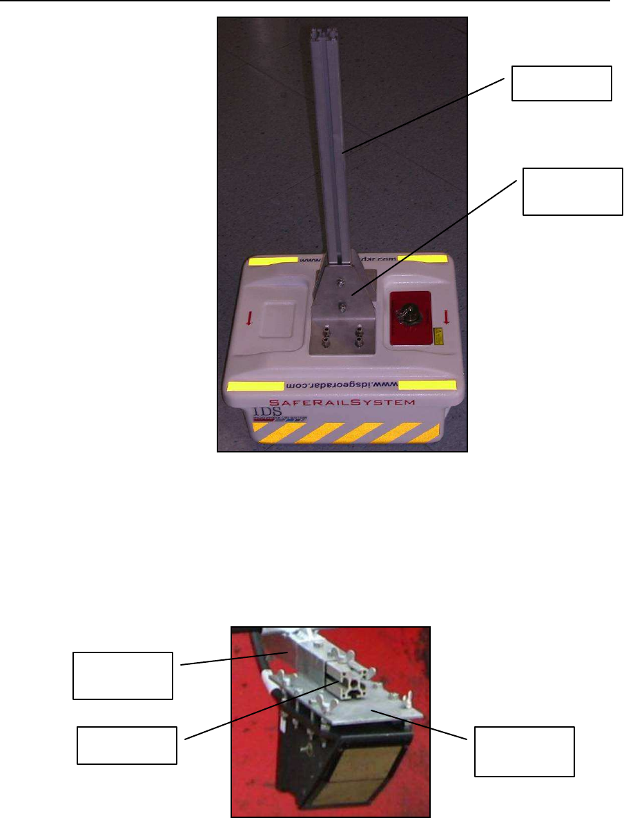
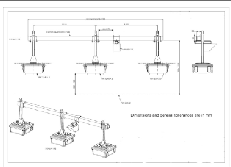
2.7 Mechanical kit
IDS provides to offer a special mechanical kit, in order to mount in a correct and efficient
way the antennas in front of the locomotive.
In details IDS provides:
• 6 supports in stainless steel with “L” shape
• 3 aluminium long bars for antennas
IDS Ingegneria Dei Sistemi S.p.A. Protocol: MN/2009/030 - Rev. 1.2
Safe Rail System Data Acquisition Software
26
/
76
Fig. 2-20 – Antenna “L” supports and bar
• 4 brackets in zinc-plated steel (3 for antennas and 1 for Doppler)
• 1 aluminium small bar for Doppler
• 1 plate of interface in zinc-plated steel for Doppler
Fig. 2-21 – Doppler supports
Antenna “L”
support
Antenna bar
Bracket
Small bar
Plat
e of
interface
IDS Ingegneria Dei Sistemi S.p.A. Protocol: MN/2009/030 - Rev. 1.2
Safe Rail System Data Acquisition Software
27
/
76
Fig. 2-22 – Sketch of SRS layout
IDS Ingegneria Dei Sistemi S.p.A. Protocol: MN/2009/030 - Rev. 1.2
Safe Rail System Data Acquisition Software
28
/
76
3. SOFTWARE CONFIGURATION OF THE SRS SYSTEM
This chapter describes the SW procedures you have to follow to correctly perform
a radar data acquisition.
3.1 Software Installation and configuration
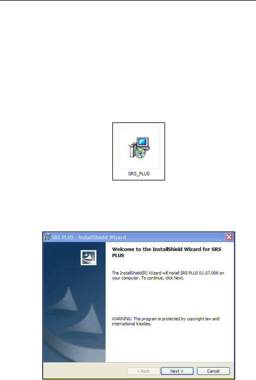
Install the SW SRS_PLUS Kit as follows:
STEP1
execute the
SRS_PLUS.msi
file in the electronic support that comes
along with the instruments (Flash memory or CD).
Fig. 3-1 – SW SRS_PLUS installation Kit
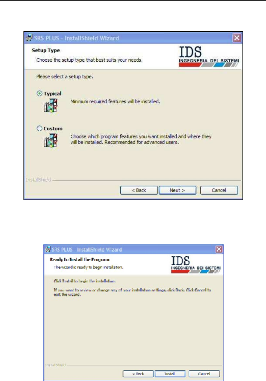
STEP2
continue SW SRS_PLUS installation pushing NEXT.
Fig. 3-2 – Installation Kit, Next button
IDS Ingegneria Dei Sistemi S.p.A. Protocol: MN/2009/030 - Rev. 1.2
Safe Rail System Data Acquisition Software
29
/
76
STEP3
select TYPICAL and press NEXT to continue.
Fig. 3-3 – Installation Kit, Typical button
STEP4
Press INSTALL to continue SW SRS_PLU S installation.
Fig. 3-4 - Installation Kit, Install button
IDS Ingegneria Dei Sistemi S.p.A. Protocol: MN/2009/030 - Rev. 1.2
Safe Rail System Data Acquisition Software
30
/
76
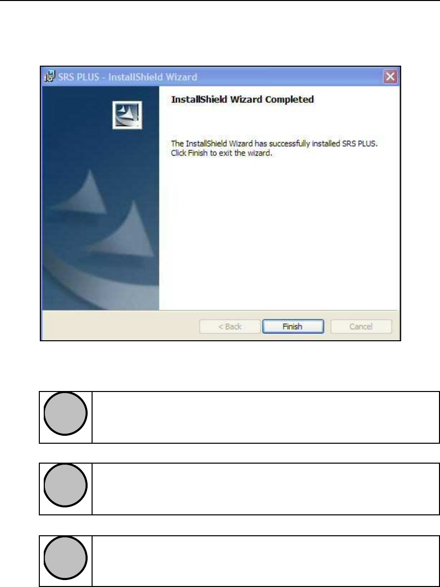
STEP5
the installation procedure will terminate pressing FINISH, and the SW
SRS_PLU S icon will appear on the portable computer desktop.
Fig. 3-5 – Installation Kit, Finish button
!
NOTE
The functions of the
SRS_PLUS
acquisition SW are only guaranteed
on computers operating with Windows 2000 or Windows XP
Professional.
!
NOTE
Check that the
SRS_PLUS
directory is copied into the
C:\
drive and is
not write protected, otherwise the
SRS_PLUS
SW will not function
correctly.
!
NOTE
Check that the
SRS_PLUS
directory is copied into the
C:\
drive and is
not write protected, otherwise the
SRS_PLUS
SW will not function
correctly.
In order to keep the same network settings we suggest to create a user account
properly dedicated for GPR software.
IDS Ingegneria Dei Sistemi S.p.A. Protocol: MN/2009/030 - Rev. 1.2
Safe Rail System Data Acquisition Software
31
/
76
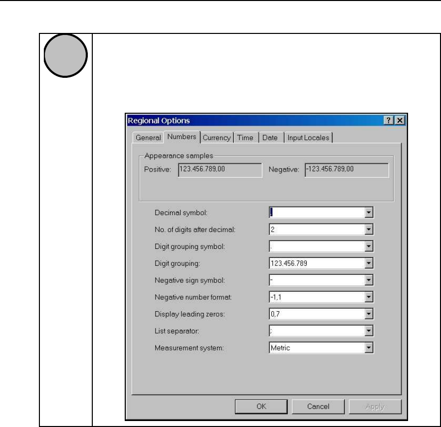
!
NOTE
During installation, software SRS_PLU S will install automatically
international settings. To guarantee the correct functioning of the
S
RS_PLU S SW, set the following configuration in the Numbers field
of the Regional Options menu.
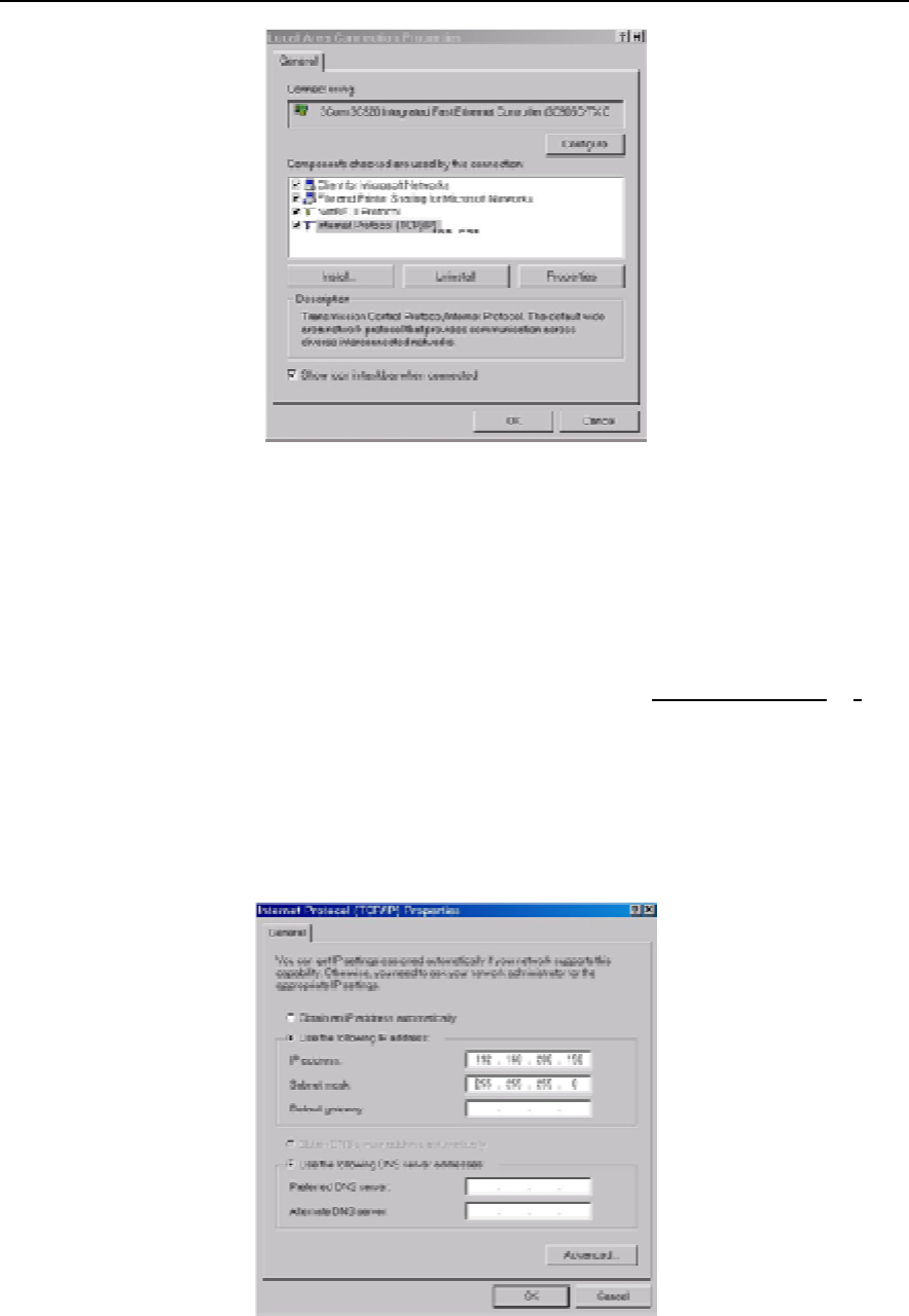
Then the user has to set manually the
Notebook Computer
TCP/IP address,
following the procedure described below.
•
Select the
my network places
icon from the
Notebook Computer
desktop
with the right mouse button;
•
Select the
Properties
button
.
•
Select the
Local Area Connection (LAN)
file with the right mouse button.
•
Select the
Properties
command.
•
Select
Internet Protocol (TCP/IP)
from the list of components
(in the
general menu) with the left mouse button (see Fig. 3-6).
•
Select the
Properties
command
IDS Ingegneria Dei Sistemi S.p.A. Protocol: MN/2009/030 - Rev. 1.2
Safe Rail System Data Acquisition Software
32
/
76
Fig. 3-6 – Selecting the Internet Protocol (TCP/IP)
•
The window shown in Fig. 3-7 appears, in which you have to select
Use
the following IP address.
•
Write the following number in the
IP
address field: 192 . 168 . 200 . 199. It
is necessary that the last number of the series is different by 200 (in Fig.
3-7 it is 150).
•
Write the following number in the
Subnet mask
field: 255 . 255 . 255 . 0.
•
Press OK to confirm the changes
•
Restart the
Notebook Computer
if requested to do so to activate the
modifications made to the internet protocol.
Fig. 3-7 – Modifying the IP code
IDS Ingegneria Dei Sistemi S.p.A. Protocol: MN/2009/030 - Rev. 1.2
Safe Rail System Data Acquisition Software
33
/
76
4. SRS ACQUISITION SOFTWARE
The SRS_PLU S acquisition software is used to manage the phases of radar
acquisition and to review the data acquired directly on site.
The op erative phases of the SRS_PLUS acquisition software occur in the
following sequence:
1. Start up the SRS_PLUS software
2. Choose the configuration
3. Set up the calibration
4. Choose the survey
5. Set the acquisition parameters
6. Acquire the radar data
7. Review the data
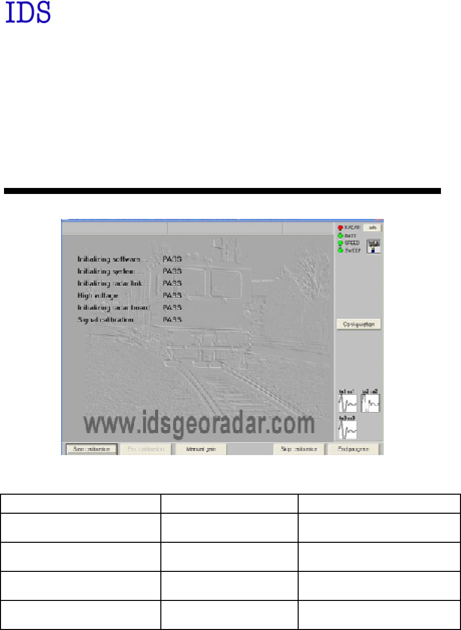
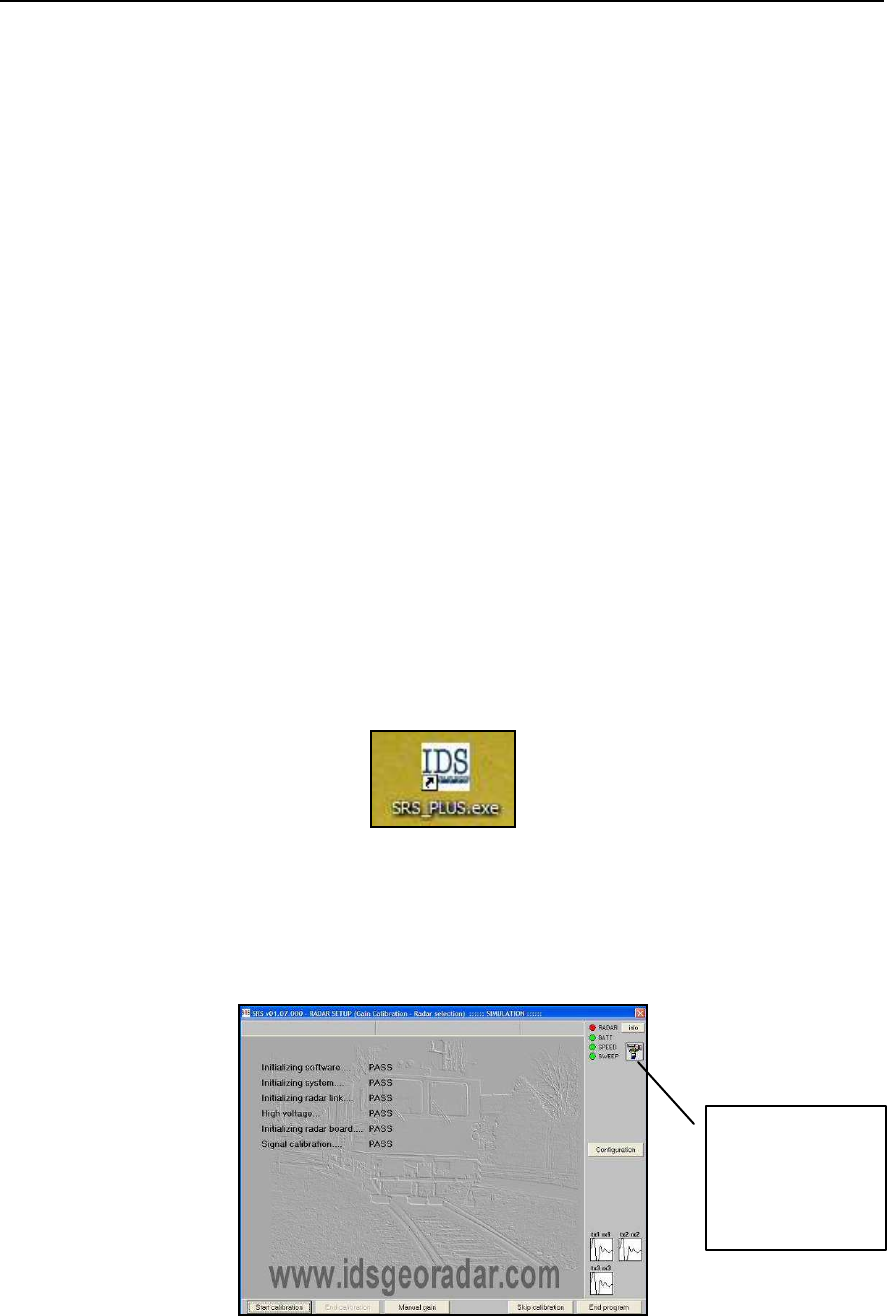
4.1 Starting the SRS_PLUS acquisition software
Once the Notebook Computer has been switched on, and the start up button on the
Control Unit has been pressed (a blue indicator light will be continuously lit),
open the
SRS_PLUS
acquisition software by clicking on the desktop icon shown
in Fig. 4-1.
Fig. 4-1 – Acquisition Software icon
Fig. 4-2 shows the SRS_PLUS acquisition software start up window.
Fig. 4-2 – SRS_PLUS acquisition software startup window
ICON
INDICATING
ACTIVATION
OF THE
CAMERA
IDS Ingegneria Dei Sistemi S.p.A. Protocol: MN/2009/030 - Rev. 1.2
Safe Rail System Data Acquisition Software
34
/
76
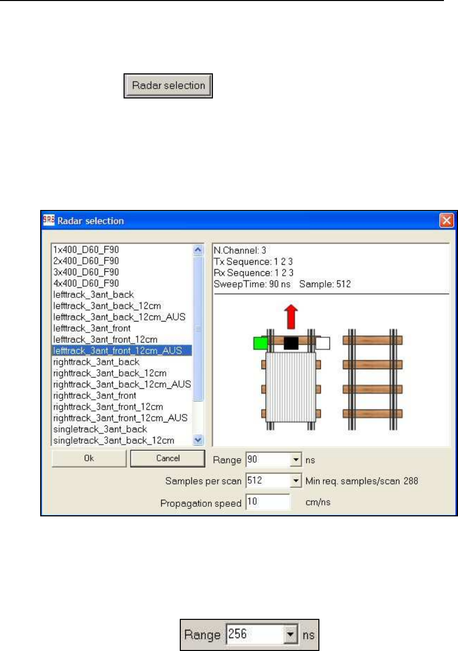
4.2 Choosing the configuration
The steps to be followed for choosing the required radar configuration for the
acquisition are given below.
1.
Press the button (Fig. 4-2) to open the
Radar selection
window (Fig. 4-3). This is where you can choose the antenna type and
configuration for the acquisition. In the example shown in Fig. 4-3, the
user has choosen a configuration file from the list. This file corresponds to
an array of 3X400M Hz antennas. Naturally the user can choose different
types of configuration for the SR S_PLUS sy stem, as shown in Fig. 4-3,
selecting a configuration of between 1 and 3 antennas.
Fig. 4-3 – Radar selection window
2.
The range can be changed with respect to the preset value by typing the
new value in the
Range
field (Fig. 4-4).
Fig. 4-4 – Range field
IDS Ingegneria Dei Sistemi S.p.A. Protocol: MN/2009/030 - Rev. 1.2
Safe Rail System Data Acquisition Software
35
/
76
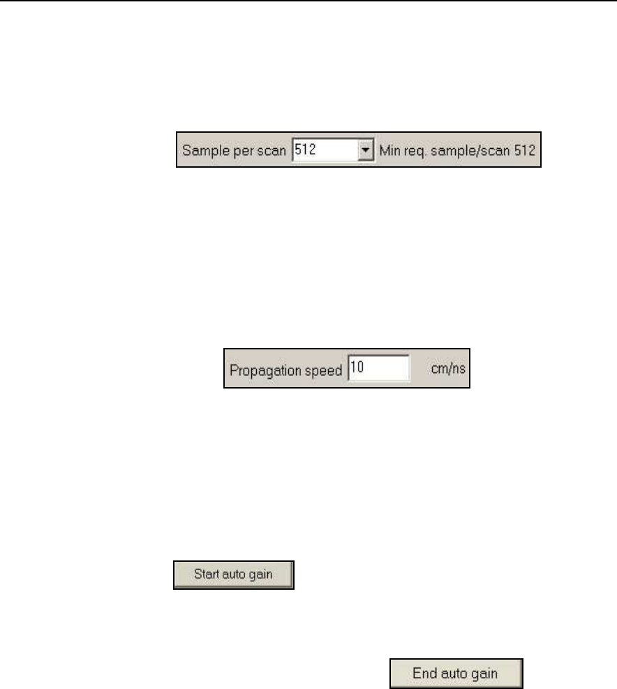
3.
The number of
Samples per scan
can be varied by choosing one of the
preset values available in the
Sample per scan
field (Fig. 4-5). However,
this value can’t be lower than the one indicated in the
Min req.
sample/scan
.
Fig. 4-5 – Samples per scan
4.
The electromagnetic wave propagation speed can then be set in the
Propagation speed
field (see Fig. 4-6). We recommend you accept the
default value unless you have specific information on the types of ground
present in the area to be investigated.
Fig. 4-6 – Propagation speed field
4.3 Setting up the Calibration
This paragraph describes the procedure used to calibrate the p arameters used in
the real-time processing of radar data.
1.
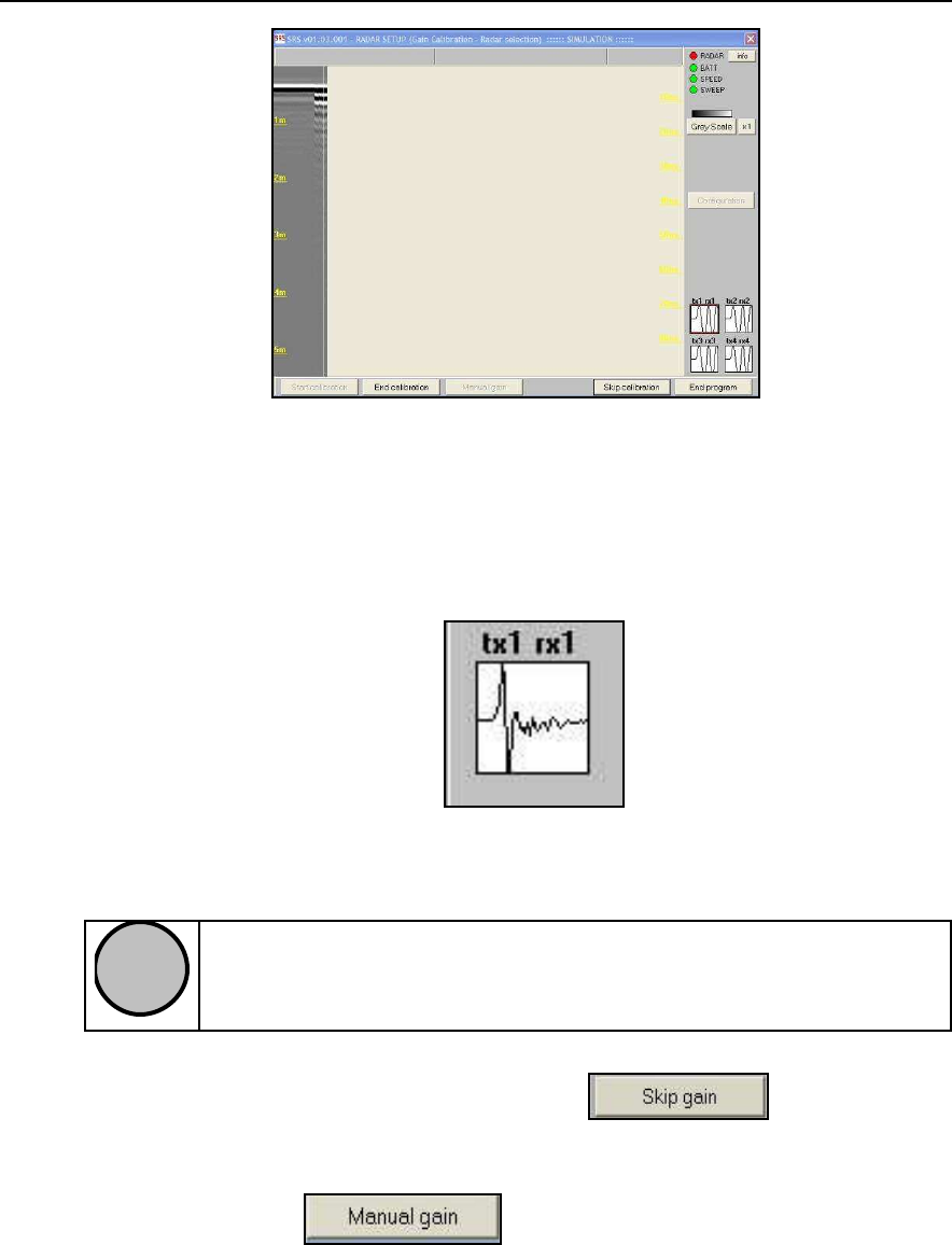
Press the button shown in Fig. 4-2 to view the window
shown in Fig. 4-7, then p erform the automatic calibration p rocedure by
moving the antennas across the surface to be scanned for a distance of at
least one meter.
2.
Stop the calibration phase by pressing the button in the
window shown in Fig. 4-7. This permits the system to save the filter
parameters required to view the radar map s in real time.
IDS Ingegneria Dei Sistemi S.p.A. Protocol: MN/2009/030 - Rev. 1.2
Safe Rail System Data Acquisition Software
36
/
76
Fig. 4-7 – Gain calibration underway
3.
You can check in the sweep display window that each antenna displays a
radar signal (see Fig. 4-8); this display window is found in Fig. 4-7.
Fig. 4-8 – Controlling the presence of radar signal on the antenna/s
!
NOTE
A lack of signal in the window shown in Fig. 4-8
should warn you that
the system is not operating
4.
You can skip this phase by pressing the button shown in
Fig. 4-7, but this means that you can only review pre-existing radar data,
and not acquire new data.
5.
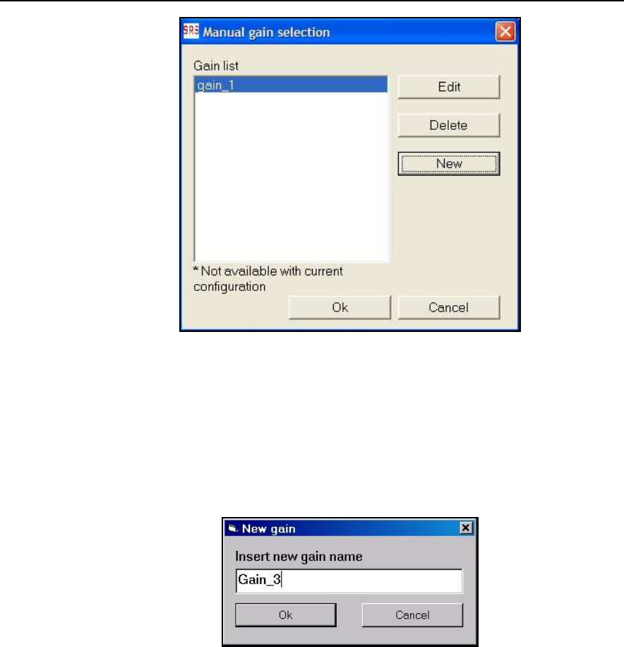
Pressing the button opens the window shown in Fig.
4-9, from where you can edit, delete or create a new gain calibration file.
IDS Ingegneria Dei Sistemi S.p.A. Protocol: MN/2009/030 - Rev. 1.2
Safe Rail System Data Acquisition Software
37
/
76
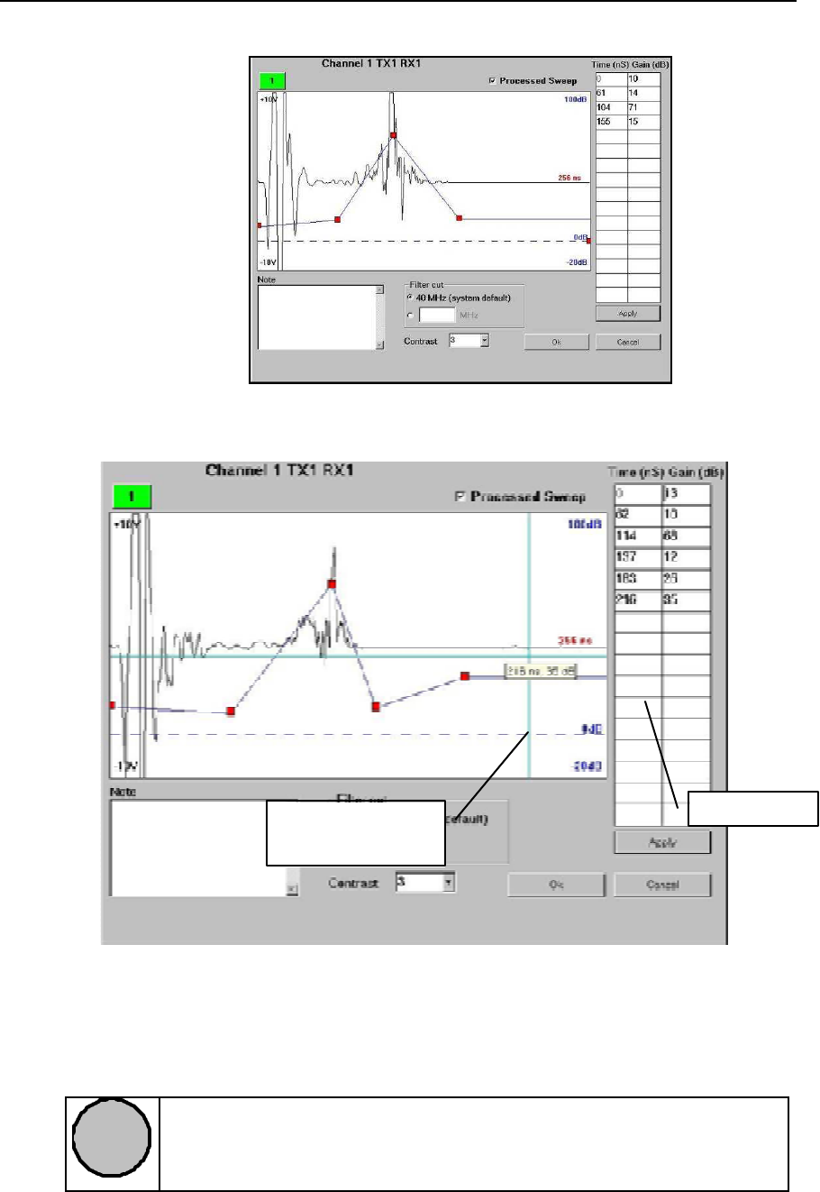
Fig. 4-9 –Calibration file selection window
Pressing the
New
button from the window of Fig. 4-9 opens the window
shown in Fig. 4-10 from where you can edit the calibration filename. Now
press the
OK
button to open the window shown in Fig. 4-11, from where you
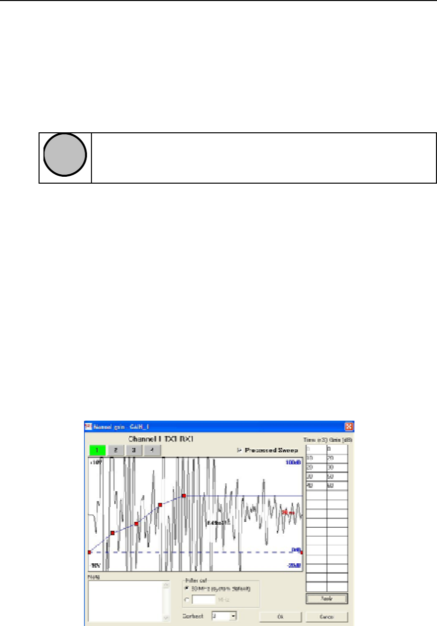
can set the gain values to apply on the radar map.
Fig. 4-10 – Gain window
The following parameters can be set in the window shown in Fig. 4-11
•
the time in nsec in the
Time
column,
•
the value of gain to app ly on the radar map based on the values set in the
Gain
column.
Then pressing the
Apply
button, you can draw the gain curve based on these
values.
As an alternative to the above procedure, you can use the graphics mode,
which consists of manually inserting the individual points of the gain curve.
To activate this procedure:
o
point with the mouse on the red square on the right edge of the
window, corresponding to the value 0dB (Fig. 4-12 and Fig. 4-13)
IDS Ingegneria Dei Sistemi S.p.A. Protocol: MN/2009/030 - Rev. 1.2
Safe Rail System Data Acquisition Software
38
/
76
o
the square has been successfully selected when it becomes bigger
o
now click with the right mouse button, the cursor will become a
cross that can move across the entire window
o
click with the right mouse button to position a point on the gain
curve on the graph; a text box linked to the cursor will indicate the
value in
ns
and
dB
of the p oint you intend to fix.
!
NOTE
A gain curve can only be reapplied to configurations with the same
starting conditions
You can app ly the gain curve you desire to each single channel simply by
selecting the desired channel nu mber beforehand.
You can choose from the following options shown in Fig. 4-11:
• Processed Sweep
activating this function, you can visualize how to
modify the sweep as a function of the chosen gain curve.
• Filter cut:
here you can select the cut frequ ency to apply to the sweep .
You can either choose the preset value of 100MHz or set a different
value in the dedicated textbox; we do howev er suggest you select the
preset cut frequency value of 100M Hz.
• Contrast:
you can select the contrast value here to be applied to the
radar map .
• Note:
you can write any comments here about the calibration file just
created.
Fig. 4-11 – Gain parameter settings window
Channel activated
which the gain curve
will be applied to
Gain curve
IDS Ingegneria Dei Sistemi S.p.A. Protocol: MN/2009/030 - Rev. 1.2
Safe Rail System Data Acquisition Software
39
/
76
Fig. 4-12 – Graphical construction of the gain curve
Fig. 4-13 – Manual construction of the gain curve
!
NOTE
The gain values set in the window shown in Fig. 4-11
are only applied
to the radar map during the visualisation phase, they are not ap plied to
the *.DT raw data file
Cursor for manually
positioning points
Range value
IDS Ingegneria Dei Sistemi S.p.A. Protocol: MN/2009/030 - Rev. 1.2
Safe Rail System Data Acquisition Software
40
/
76
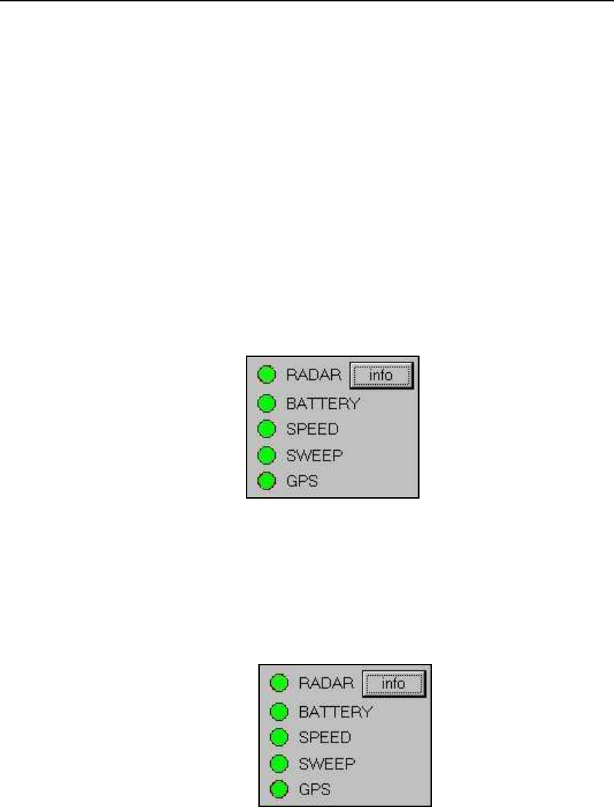
6.
The spy lights representing the radar (
RADAR
), battery (
BATT
),
acquisition speed (
SPEED
) and acquired sweeps (
SWEEP
), shown in
Fig. 4-7, indicate the functional status of the system (see Fig. 4-14).
When the spy lights are coloured
• White:
this means the system is not active
• Green:
this means the system is functioning correctly
• Red:
this means the system is not functioning correctly
The
GPS
spy light shows the connection with a GPS system connected to
the
Notebook Computer.
Appendix H describes the procedure for
connecting the GPS system to the radar.
The battery spy light changes co lour from green through yellow to red,
representing the decreasing level of charge remaining.
Fig. 4-14 – The system function spy lights
7.
There is an
info
button next to the RADAR spy light (Fig. 4-15).
Pressing this button automatically op ens the window shown in Fig.
4-16, which shows all the parameters set for the current configuration.
Fig. 4-15 – Info button
IDS Ingegneria Dei Sistemi S.p.A. Protocol: MN/2009/030 - Rev. 1.2
Safe Rail System Data Acquisition Software
41
/
76
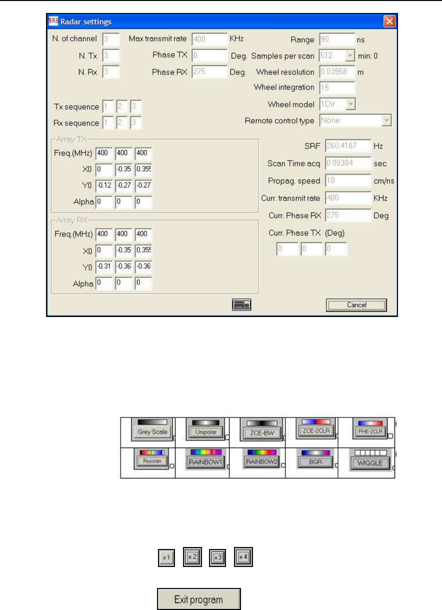
Fig. 4-16 – Info window
8.
Pressing the colour scale button shown in the window in Fig. 4-7, you
can choose one of the 10 types of colour palettes available for
disp laying the radar maps (see Fig. 4-17).
Fig. 4-17 – Colour palettes available
9.
You can zoom in on the maps up to a magnification of four times by
pressing the
, , ,
buttons in the window shown in Fig.
4-7.
10.
Pressing the button in the window shown in Fig. 4-7
closes the software. Before shutting down, the software displays a
message window reminding you to switch off the Radar Control Unit
(see Fig. 4-18).
IDS Ingegneria Dei Sistemi S.p.A. Protocol: MN/2009/030 - Rev. 1.2
Safe Rail System Data Acquisition Software
42
/
76
Fig. 4-18 – Program shut-down window
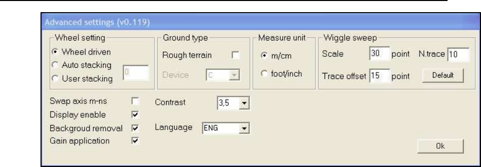
4.3.1 Advanced Settings Menu
The
Advanced Settings
menu
(
Fig. 4-20
)
can be selected by clicking on the
SRS_PLU S icon in the top left corner of the main window of the SW (Fig. 4-19),
or by mouse clicking twice on the grey bar at the top of the window.
Fig. 4-19 – Activating the Advanced settings menu
This menu allows you to set the following parameters:
• Wheel setting
here you can set the acquisition mode of the system, which
can be either
o Wheel driven
field selected, in this mode, the radar acquisition is
set using the position sensor.
o
If the wheel is not used, y ou can set the radar acquisition to be
performed under a constant time regime; the value inserted in the
Auto
Stacking
field indicates the number of sweeps averaged
during the acquisition phase.
o
The User Stacking function on the other hand allows you to control
the number of sweeps averaged. The acquisition is still controlled
in this configuration by the p osition sensor (wheel, hip-chain
encoder or manual trigger). Once the signal from the position
sensor has been received, the system performs an average of the
number of sweep s selected by the user and emits an acoustic signal
to confirm that the data has been saved.
IDS Ingegneria Dei Sistemi S.p.A. Protocol: MN/2009/030 - Rev. 1.2
Safe Rail System Data Acquisition Software
43
/
76
Fig. 4-20 –Advanced Settings window
•
The
Ground type
field enables y ou to activate the
Rough terrain
option
if necessary. When this option is activated, the radar data are temporarily
saved on the selected
Device
during the acquisition phase. You can even
select an external
Device
such as a flash memory to temporarily save the
data during the acquisition p hases. This option is recommended when the
ground conditions are particularly rough, and when you may find that
saving the data during the acquisition phase becomes critical due to the
high number of vibrations in the system.
•
In the
Measure unit
field, y ou can choose the measurement units to be
applied to the radar map visualized in real time. The alternatives are
m/cm
and
foot/inch
•
In the
Wiggle sweep
field,
you can select the parameters for visualising the
acquired data in real time in Wiggle mode;
o Scale
represents the signal amplification
(intended as the number of
pixels into which the -10V a +10V vector scale is mapped),
o N. trace
represents the “x” interval
of the viewed traces (i.e. that
one sweep is viewed every “x” traces),
o Trace offset
is on the other hand the representation interval
between adjoining traces (i.e. also in this case the number of pixels)
o Default
Buttons
saves the p reset settings as the default
configuration.
•
In the
Swap axis
field, you have the choice of modifying the vertical scale
of the radar map by setting the value in
m
or
nsec
•
In the
Gain application
field, y ou can choose to view the radar map
acquired in real time with or without gain applied
•
In the
Background removal field
you can set the Clear_x application for
the acquired radar maps.
•
In the
Display enable
you can activate the display mode of the radar
section during acquisition phase.
IDS Ingegneria Dei Sistemi S.p.A. Protocol: MN/2009/030 - Rev. 1.2
Safe Rail System Data Acquisition Software
44
/
76
•
In the
Contrast
field, you can choose the contrast level to be applied to the
radar map viewed in real time.
Activating the
Virtual Keyboard
and
Windows Start
and
Close
commands (Fig.
4-19) opens the virtual keyboard, the windows start menu and closes the
SRS_PLU S SW respectively. The
Move
command is not yet active. For details on
the
External device setting
command, see Appendix E, page 52.
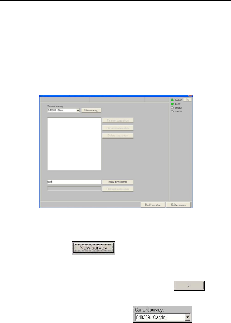
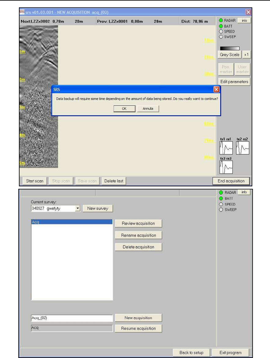
4.4 Choosing a survey
After the calibration phase, the acquisition procedure continues with the
appearance of the following window shown in Fig. 4-21.
Fig. 4-21 – Acquisition Selection window
1.
Pressing the button in Fig. 4-21 opens the window shown
in Fig. 4-22, in which you have to type the name of the survey in the top
text box; any notes relating to the survey can be inserted in the lower text
box.
2.
Complete the survey selection p hase by clicking the button in
the window shown in Fig. 4-22; this will return you to the window shown
in Fig. 4-21. The chosen name and date of creation are automatically
inserted into the current survey box shown in Fig.
4-21.
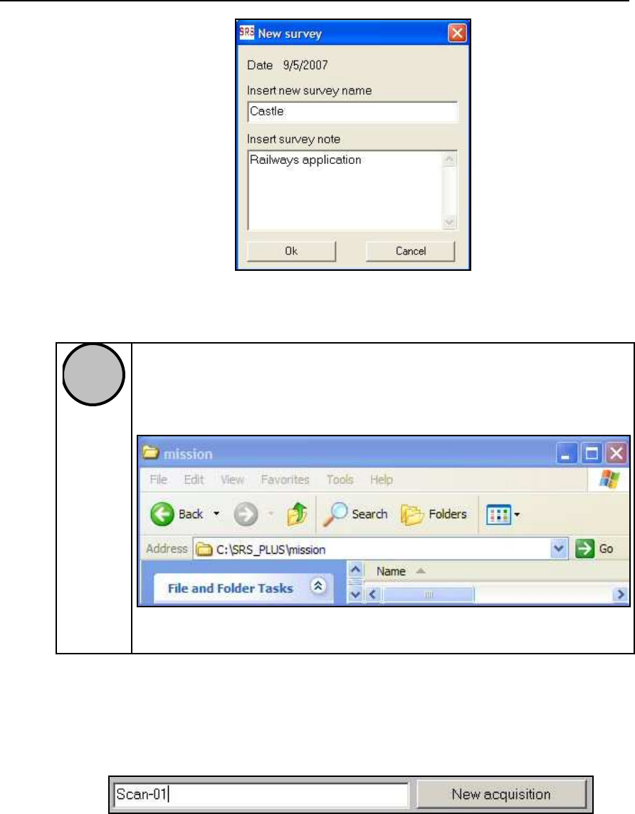
IDS Ingegneria Dei Sistemi S.p.A. Protocol: MN/2009/030 - Rev. 1.2
Safe Rail System Data Acquisition Software
45
/
76
Fig. 4-22 – New Survey window
!
NOTE
Once a new survey name has been chosen, a new fo lder is
automatically created with this name and the .
mis
extension in the
C:\SRS_PLUS\M ission\*.mis directory, as shown below.
Fig. 4-23 – The *.mis folder directory
4.
At this point, type in the name of the new acquisition in the text box shown
in Fig. 4-24, which is part of the window shown in Fig. 4-21. The name
inserted in the example given in Fig. 4-24 is
Scan-01
.
Fig. 4-24 – NEW ACQUISITION text box
5.
You can then move on to the acquisition phase by pressing the
New
acquisition
button shown in Fig. 4-24, which is part of the window shown
in Fig. 4-25.
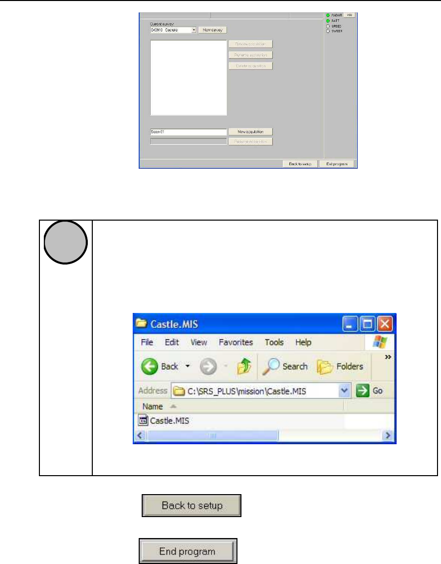
IDS Ingegneria Dei Sistemi S.p.A. Protocol: MN/2009/030 - Rev. 1.2
Safe Rail System Data Acquisition Software
46
/
76
Fig. 4-25 – Setting up a New Acquisition
!
NOTE
Once you have defined the name of the new acquisition, a new folder
is automatically created with this name and the
.zon
extension in the
C:\SRS_PLUS\M ission\*.mis\*.zon directory, as shown in Fig. 4-26
:
the example shows the C:\SRS_PLU S\M ission\Castle.mis\*.zon
directory.
Fig. 4-26 – The Castle.mis folder directory
6.
Pressing the button returns to the calibration phase
window shown in Fig. 4-7.
7.
Pressing the button in the window shown in Fig. 4-7
closes the software; before shutting down the software, the message
window shown in Fig. 4-18 reminds you to disconnect the Control Unit.
4.5 Setting the acquisition parameters
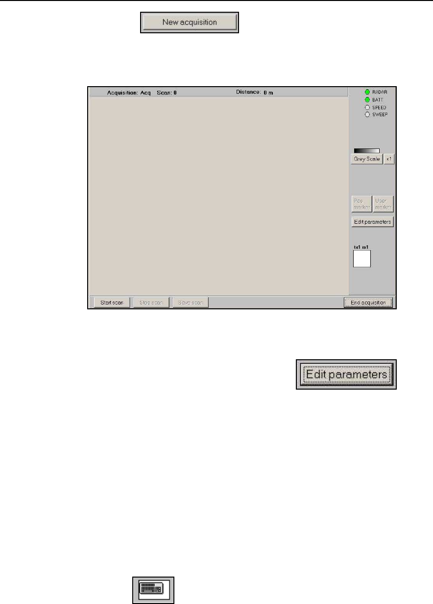
Once the names of the survey and acquisition have been chosen, you can p ass
straight on to the data acquisition p hase.
IDS Ingegneria Dei Sistemi S.p.A. Protocol: MN/2009/030 - Rev. 1.2
Safe Rail System Data Acquisition Software
47
/
76
1.
Pressing the button on the window shown in Fig.
4-25 automatically produces the
NEW ACQUISITION
window shown in
Fig. 4-27.
Fig. 4-27 – NEW ACQUISITION Window
2.
To set the starting point coordinates, press the button
from the window shown in Fig. 4-27; this opens the window shown in Fig.
4-28.
3.
The following acquisition parameters can be selected from the window
shown in Fig. 4-28:
i.
File prefix:
this consists of two fields which you can fill as you
wish. These fields form part of the scan identification (for example
you could use the initials of the street name). These two characters,
positioned after the first character which is either L or T deriving
from the next cho ice (see the following point), make up the second
and third of the 8 characters that identify the name of each single
section.
ii.
The button allows you to open a virtual keyboard you can
use to edit the scan coordinate values.
IDS Ingegneria Dei Sistemi S.p.A. Protocol: MN/2009/030 - Rev. 1.2
Safe Rail System Data Acquisition Software
48
/
76
Fig. 4-28 – Acquisition Parameters Window
iii.
Marker 1 step:
this field rep resents the distance between two
reference lines marked on the site. The default value is 10 m. This
function allows you to realign the radar sections to compensate for
any distance variations with respect to the data acquired with the
position sensor wheel. This realignment is performed according to
the value set in the
Marker 1 step box
. This setting is typically
used for realigning longitudinal scans. If you set the marker with a
sp ecific p osition and then p ress the button shown in Fig. 4-29,
contained in the window shown in Fig. 4-31 at a distance of
±
20%
either before or after this assigned point, the
Pos. Marker
will be
transformed into a
User Marker
when the file is saved (see Fig.
4-31 and point 3 of Par. 4.6).
Fig. 4-29 – Pos. marker button
iv.
Longitudinal/Transversal – Inverse direction:
this field allows
you to select the scanning direction of the radar section about to be
acquired. When filling in this field, remember that
Longitudinal
(
L
)
means the scans is performed parallel to the zero referen ce line (T
axis), while a scan perpendicular to this line is called a
Transversal
scan
(
T
) (see Appendix A). The
Inverse direction
field allows you
to perform a T/L scan in the opposite direction, i.e., moving in a

IDS Ingegneria Dei Sistemi S.p.A. Protocol: MN/2009/030 - Rev. 1.2
Safe Rail System Data Acquisition Software
49
/
76
decreasing coordinate direction. In any case, you must return back
to the same starting axis used for the forward scan.
v.
Coordinate (m)
: This field allows you to insert the values of the
set T or L co-ordinate. R emember to indicate if a coordinate is
negative. Check the current T or L coordinate on the site and insert
it into the relative field. Remember that, desp ite the actual
dimensions of the antenna trolley, it is represented in the Cartesian
reference system by a single point that corresponds to its
centerpoint. The position of this point varies depending on the
array configuration that has been set. When moving the antenna
trolley, make sure the centerpoint is on the scan line, at the defined
coordinate.
Coord. value
: insert the value of the coordinate to be
maintained constant during the scan in this field.
Coord. Step
: this field contains the step value that is added
automatically to the current value when a scan is finished ,
leaving the system ready to start the next scan. The preset value
= 2 m between scans. For example, if a longitudinal scan has
been chosen and it starts from a point with coordinates
T, L
=
0;+2 m, the following values must be set:
•
Longitudinal;
•
2 in the Coord value field;
•
2 in the Coord. Step field.
Once the scan is finished, the coordinate of the L v alue is
automatically positioned on the value 4.
!
BE CA REFUL
The Antenna array may only be moved in one direction. It may only be
pulled or pushed in the direction of increasing scanning coordinates, the
only exception being when the
Inverse Direction
field is activated
.
vi.
Scan Offset (m)
: each radar scan is characterised by an initial L
and/or T co-ordinate Therefore, once you have inserted the starting
point co-ordinate for the investigation (“
coord. value
” in Fig. 6-9)
as a function of the type of scan, the other reference co-ordinate
must be defined in the “
Scan Offset (m)
” field. There are two
alternatives for this operation:
Select “
With 1st Marker 1 step
”: this selection automates
the insertion of the second L or T co-ordinate when the
antenna array crosses the zero line starting from a negative
co-ordinate. This procedure is normally used when there are
many irregularities on the site such as parked cars, indents

IDS Ingegneria Dei Sistemi S.p.A. Protocol: MN/2009/030 - Rev. 1.2
Safe Rail System Data Acquisition Software
50
/
76
in the pavement, etc. In these cases, it can be very time
consuming to calculate the distances each time as described
above and is more convenient to select the
With 1st
Marker 1
box after having just set the initial L or T co-
ordinate.
The system automatically reco gnises the path performed in
the negative portion and automatically associates the
negative starting co-ordinate to the last L or T co-ordinate.
For example, for the case of the Transversal scans shown in
Fig. 4-30, first we select the scan type (in this case
Transversal) in the “
Scan Settings
” window (Fig. 4-28).
Then we set the current value of the T co-ordinate (2m in
this case) in the “
Coordinate (m)
” field; finally, we activate
the “
With 1
st
Marker”
option in the “
Scan Offset (m)
” field.
In this way, the acquisition starts in the negative L p ortion,
and when the centerpoint of the antenna trolley passes
across the zero line, the M arker 1 button has to be pressed.
The trolley is then pushed to the end of the scan. When the
stop acquisition button is pressed, the system automatically
associates a negative co-ordinate to the initial portion of the
file of the scan that has been performed
“
On
L/T coordinate
” selection
In this case, you have to manually measure the value of the
co-ordinate corresponding to the centerpoint of the antenna
array with resp ect to the reference system selected
previously, and insert it into the active field.
For example, if y ou have to perform a transversal scan
starting from the co-ordinate T=2 and L=2, you must set the
type of scan to Transversal and then set the actual value of
the T co-ordinate (e.g. 2 m) in the “
Coordinate (m)
” field.
Next, activate the “
L coordinate
” in the “
Scan Offset (m)
”
area, setting it to 2 in this case. The scan can now be
performed.
!
BE CA REFUL
In “
With 1
st
marker 1 step
” mode, the antenna system must be moved at
least 20 cm after having pressed the
Pos. Marker
button shown in Fig. 4-29
before pressing the stop button; otherwise the section cannot be viewed by
the elaboration SW.
IDS Ingegneria Dei Sistemi S.p.A. Protocol: MN/2009/030 - Rev. 1.2
Safe Rail System Data Acquisition Software
51
/
76
MARKER1
-4
START
START
START
START
START
L
-2
0
START
T
Scanning Direction
0
10
8
6
4
2
12
2
MARKER 1 MARKER 1
Fig. 4-30 – Diagram showing an example of how to use the function “with 1st
Marker 1 step”
4.6 Data acquisition
Once you are sure all the scan parameters have been correctly defined, you are
ready to start.
1.
Press the
button in the window shown in Fig. 4-27 and
start to move the trolley along the desired path (always in the same
direction). The results of the single sections will start to appear in real time
on the monitor in a window dedicated to channel 1 (see Fig. 4-31). The
active channel is indicated with a red box in the sweep window. When a
window is completely filled, the data will be written over from left to right
and you will notice that the content of the radar section changes line by
line. When the system passes across a possible utility or a radar target of
any type, typical hyperbola shaped figures will appear with variable
contrast in the depth direction corresponding to the impulses received. The
presence of targets can be detected by comparing these figures, window by
window, however, it is easier to perform this operation during the
processing phase. The distance travelled by the trolley (
Distance:….m
) is
shown above the radar map in real time, the depth is expressed in meters
(
m
) on the left y axis while the time delay expressed in nanoseconds (
ns
) is
given on the right y axis as indicated in Fig. 4-31. To visualize another
acquired channel in real time, you can click on the small window of the
signal corresponding to the desired channel.
IDS Ingegneria Dei Sistemi S.p.A. Protocol: MN/2009/030 - Rev. 1.2
Safe Rail System Data Acquisition Software
52
/
76
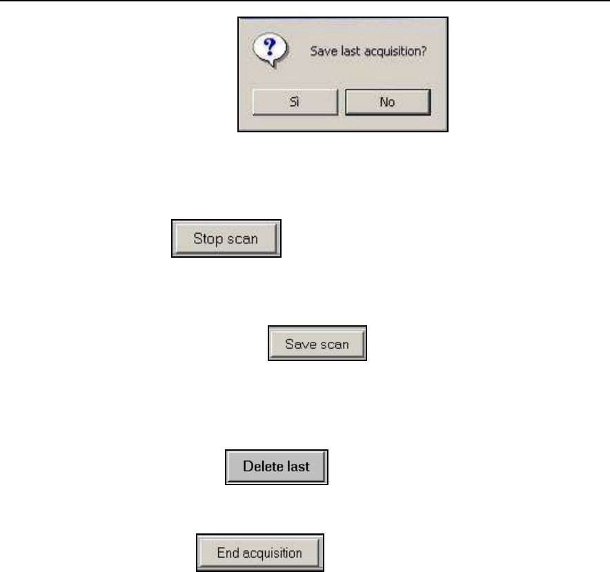
2.
When you press the
button on the window shown in Fig. 4-31, a
green line automatically appears on the section at the abscissa.
3.
When you come across objects of particular interest such as manholes or
macroscopic discontinuities, you can press the
button shown in
window Fig. 4-31; this will produce a red line at the abscissa.
Fig. 4-31 – Radar section during acquisition
4.
If you move the trolley too quickly, an alarm sounds to warn you that you
are loosing data; if this problem continues, it is best to stop the scan with
the button shown in Fig. 4-31 and avoid saving the data
by pressing the
NO
button in the window shown in Fig. 4-32.
No modifications need to be made before repeating the scan apart from
returning the trolley back to the starting position.
HYPERBOLA
CHANNEL 1
DISTANCE TRAVELLED
TIME
DELAY
DEPTH
IDS Ingegneria Dei Sistemi S.p.A. Protocol: MN/2009/030 - Rev. 1.2
Safe Rail System Data Acquisition Software
53
/
76
Fig. 4-32 – Data saving window
5.
When you want to save the acquired data on the disk, you can choose to
press the button shown in the window in Fig. 4-31, then
create the temporary file by pressing the
YES
button in the window in Fig.
4-32.
6.
But you can also choose to temporarily save the data acquired up to that
point by pressing the button shown in Fig. 4-31, and
continue to push the trolley in the same direction to the end of the scan,
then definitively save it using the above procedure. This save scan
procedure is particularly recommended for longer scans that may reach up
to a few hundred meters in length.
7.
By pressing the button, you cancel the last radar scan
performed. Once the radar map has been completely deleted, the
coordinates are updated to those of the preceding scan.
8.
Pressing the button terminates the acquisition phase,
then the software will save definitely all data storage of the same mission
by pressing the OK button in the window appearing (see upper
Fig. 4-33
);
then you move on to the window shown in Fig. 4-33 which has all the
review functions activated.
IDS Ingegneria Dei Sistemi S.p.A. Protocol: MN/2009/030 - Rev. 1.2
Safe Rail System Data Acquisition Software
54
/
76
Fig. 4-33 – Acquisition window activated for performing operations in review mode
IDS Ingegneria Dei Sistemi S.p.A. Protocol: MN/2009/030 - Rev. 1.2
Safe Rail System Data Acquisition Software
55
/
76
!
NOTE
Remember that data is grouped by scans, i.e. a group of radar sections
relating to a single passage of the radar trolley. Any group of radar
sections can be visualised from a given scan.
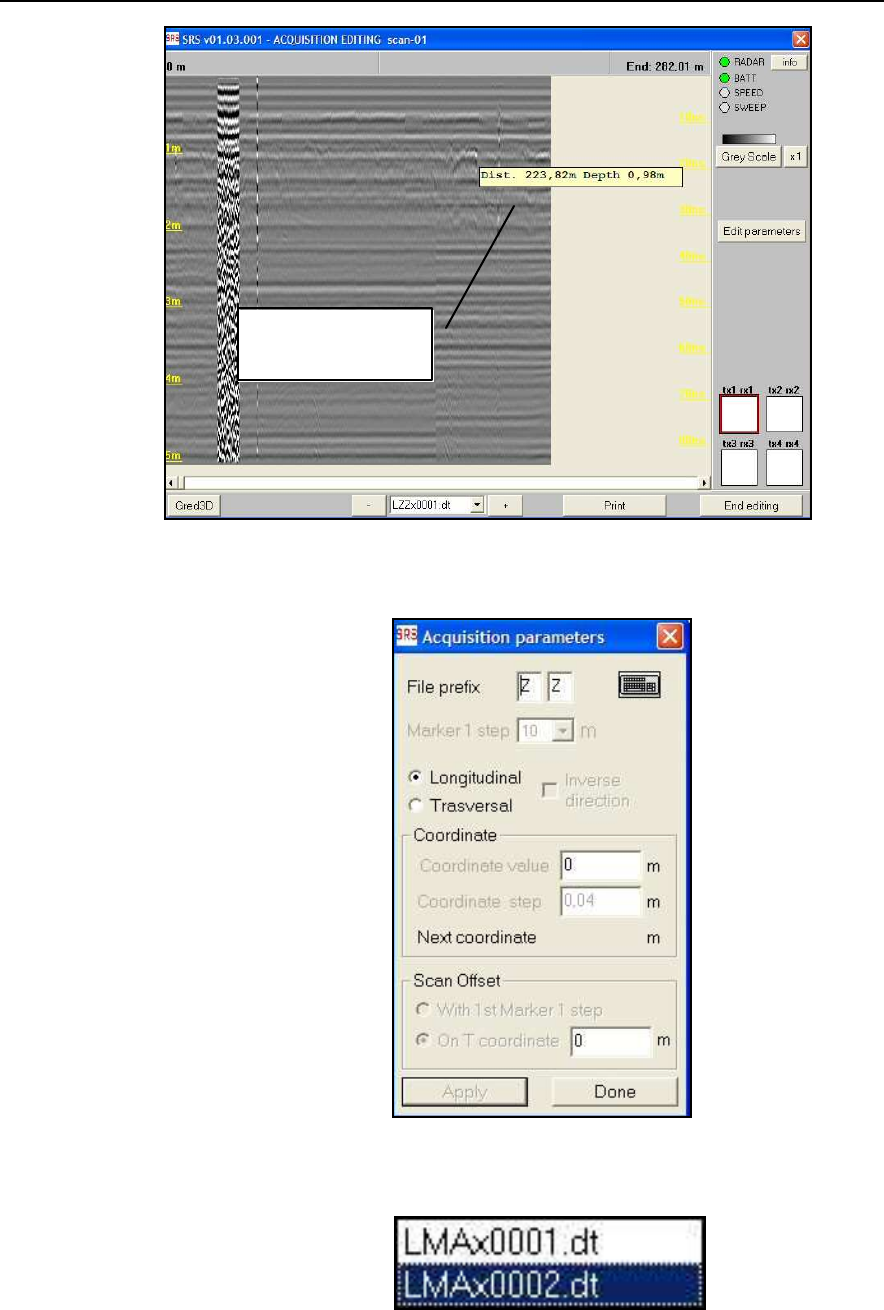
You have a list of names of saved scans available. The following
nomenclature rules apply for the scans:
1.
the scan file names have 8 characters and have the *.dt extension
before the data are processed;
2.
the filename is derived as follows:
•
1
st
character
L
or
T
depending whether the scan is
longitudinal or transversal,
•
2
nd
–3
rd
character can be chosen by the user,
•
4
th
character
*
= channel number used
•
5
th
–8
th
characters make up the progressive number of
the scan within the survey.
The first acquired file has the progressive number 0001, so for
example, the name LMA*0012.DT is the name of the twelfth scan,
performed in the longitudinal direction and contains unprocessed data.
Each channel has its own corresponding data file.
4.7 Operating in review mode
You can perform various operations on the acquired data. Once the acquisition has
been selected from the window shown in Fig. 4-33 (in the example shown here in
Fig. 4-33, the
Acq
acquisition is chosen) you can:
1.
Press the button shown in Fig. 4-33 to view the
selected acquisition.
The first radar section of the selected scan will appear (Fig. 4-34).
From this section, once the
Edit parameters
button has been pressed,
it is then possible to modify the
File prefix
field
and the
Longitudinal/Transversal
field shown in Fig. 4-35.
You can select another scan belonging to the same acquisition directly
from the window shown in Fig. 4-34, choosing the one you want from
the text box shown in Fig. 4-36 or by pressing the and
buttons to view the next or previous scans respectively.
IDS Ingegneria Dei Sistemi S.p.A. Protocol: MN/2009/030 - Rev. 1.2
Safe Rail System Data Acquisition Software
56
/
76
Fig. 4-34 – Acquisition Editing window
Fig. 4-35 – Window for Editing parameters after acquisition transversal
Fig. 4-36 – Scans from the same acquisition
Distance and
depth indications
IDS Ingegneria Dei Sistemi S.p.A. Protocol: MN/2009/030 - Rev. 1.2
Safe Rail System Data Acquisition Software
57
/
76
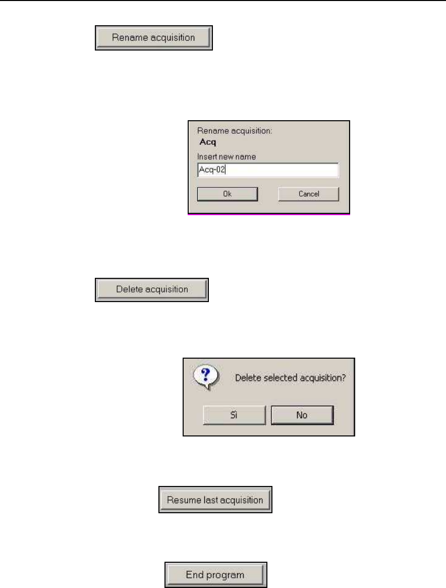
2.
The name of the selected acquisition can be changed using the
button in the window shown in Fig. 4-33.
Write the new name of the selected acquisition in the window shown in
the window in Fig. 4-37; once the new name has been set, press the
OK
button to confirm.
Fig. 4-37 – Rename Acquisition Window
3.
Any previously saved acquisition can be deleted by pressing the
button in the window shown in Fig. 4-33 using
the window shown in Fig. 4-38; the delete operation has to be
confirmed by pressing the
YES
button in this window.
Fig. 4-38 – Delete acquisition window
4.
Pressing the
button from the window shown in
Fig. 4-33 reloads the last acquisition, enabling you to continue
performing other scans in the same acquisition area, following the
procedure described in Par.4.6.
5.
Pressing the button shown in Fig. 4-7 closes
down the software. Before closing it down, the system reminds you to
disconnect the Radar Control Unit with the message window shown in
Fig. 4-18.

IDS Ingegneria Dei Sistemi S.p.A. Protocol: MN/2009/030 - Rev. 1.2
Safe Rail System Data Acquisition Software
58
/
76
5. ERROR MESSAGES AND ALARMS
5.1 Error messages
Error messages found in the program are listed below (
in italics
) followed by their
solutions:
Network error. Retry or check hardware!
Check that the network cable is connected properly to the PC and the SRS_PLUS
Control Unit. Try restarting the program.
Warning. Unable to print on the selected printer
Check that the printer is switched on and connected to the computer.
Unable to review: calibration file has been lost.
Gain calibration has been skipped (or lost). Calibrate gain to proceed..
Unavailable: gain calibration has been skipped (or lost).
Unavailable: gain calibration has changed.
A calibration has to be performed to be able to acquire data. See Paragraph 4.3 for
calibration instructions.
Unavailable: directory has been lost.
The last acquisition cannot be recovered, select a new acquisition.
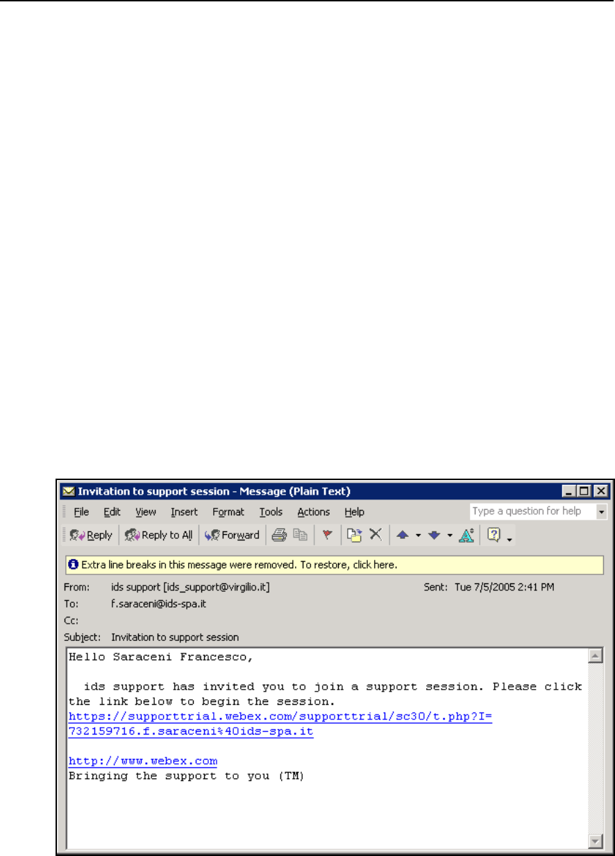
IDS Ingegneria Dei Sistemi S.p.A. Protocol: MN/2009/030 - Rev. 1.2
Safe Rail System Data Acquisition Software
59
/
76
6. ON LINE ASSISTANCE
6.1 Remote assistance using Webex Support Center
Webex Support Center is a service that allows the activation of a two host session,
making an application, or the desktop available to the other user or letting you
capture another remote desktop.
It can be used to perform web conferences and presentations.
It is easy to use thanks to its simple and intuitive interface.
Since there are no firewalls or other types of network configurations, it is a fast
and secure means of reaching any client host in any part of the world. In fact, the
client only has to accept to download a small plug used to permit the service
authentication and functioning.
6.1.1 How to use the Webex service
You will receive an email from ID S Customer Care containing a link to the
support session (see Fig. 6-1).
Fig. 6-1 – Mail sent by IDS to the client
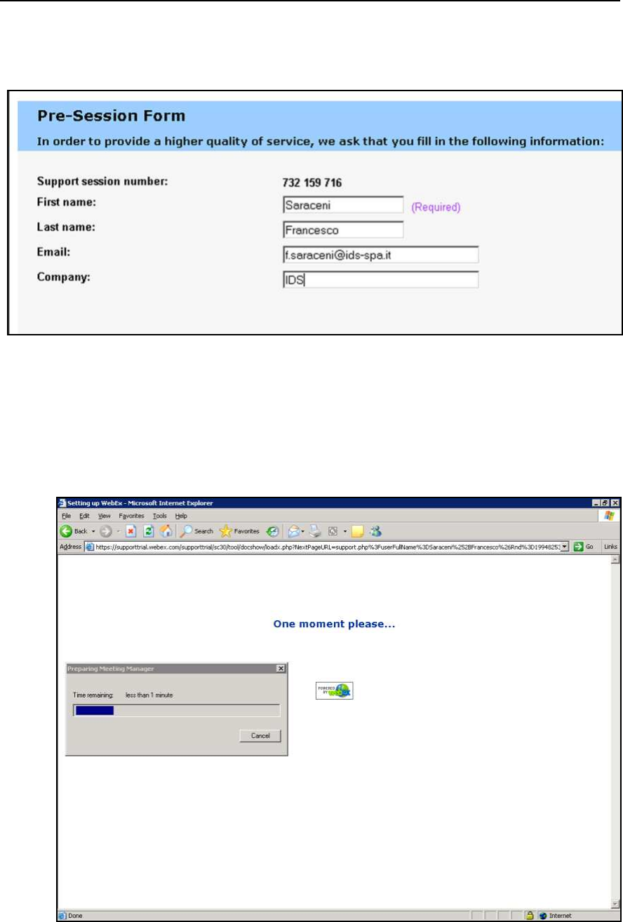
IDS Ingegneria Dei Sistemi S.p.A. Protocol: MN/2009/030 - Rev. 1.2
Safe Rail System Data Acquisition Software
60
/
76
Once you have clicked on the link sent by email, the following window will
appear. Insert your data into the form (see Fig. 6-2).
Fig. 6-2 – Client data insertion form
Once you have clicked
Submit,
the following page will appear
showing a
downloading bar. The session starts as soon as the download is complete. (see Fig.
6-3).
Fig. 6-3 – Webex Set up window
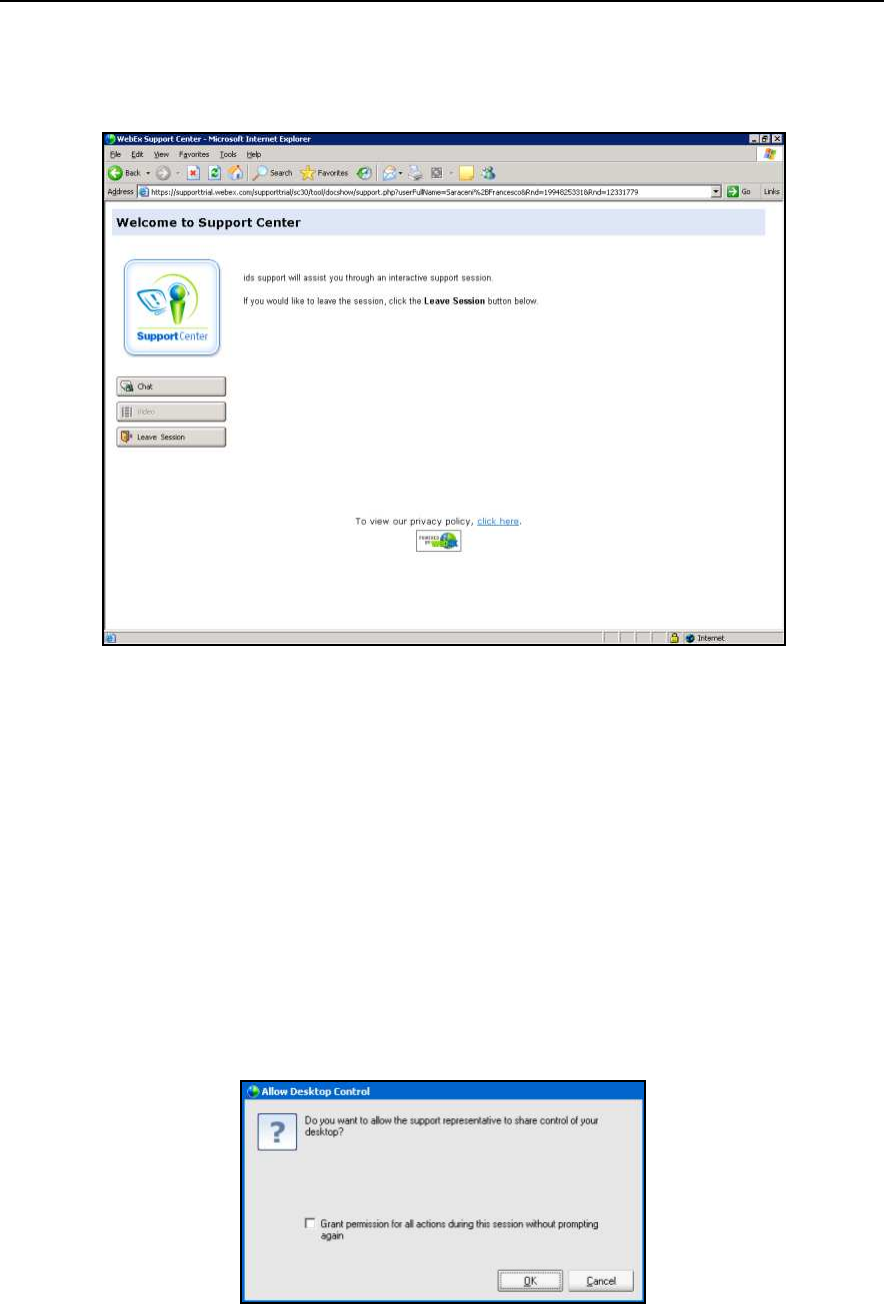
IDS Ingegneria Dei Sistemi S.p.A. Protocol: MN/2009/030 - Rev. 1.2
Safe Rail System Data Acquisition Software
61
/
76
As you can see from the following screen, (Fig. 6-4) you are given a console, just
containing the
Chat
,
Video
and
Leave Session
commands.
Fig. 6-4 – Welcome to Webex Support Center window
At this point, IDS Customer Care can perform a range of operations on your
desktop:
•
Request control of the desktop using the Request Control command.
•
Give you control of the IDS desktop using the Share Control command.
•
Request to display the remote desktop using Request View.
•
Share the visualisation of the IDS desktop using Share View.
Before each command is activated, you are asked for confirmation through the
following window (Fig. 6-5).
Fig. 6-5 – Command acceptance window

IDS Ingegneria Dei Sistemi S.p.A. Protocol: MN/2009/030 - Rev. 1.2
Safe Rail System Data Acquisition Software
62
/
76
APPENDIX A - MECHANICAL REQUIREMENTS FOR THE
INSTALLATION OF SRS SYSTEMS ON BOARD A TRAIN
A.1 - Introduction
This section deals with the installation requirements for the use of a georadar
(GPR) system on-board a train.
The system consists of:
•
a notebook computer
•
a battery
•
a GPR control unit
•
a GPR multiplexer unit
•
up to 4 GPR antennas
•
an odometer
•
and relevant connection cables.
Items 1-4 will be mounted inside the locomotive and don’t need any specific
installation; on the contrary, items 5 and 6 shall be mounted in the front of the
train and require some mechanical arrangements.
For practical reasons (mainly logistical), some of the devices needed to assure the
proper mounting of the system should be provided by SNCF; basically, these
consist of a metallic frame used to house the antennas and the brackets for fixing
this frame to the front of the locomotive.
A.2 - Mechanical requirements
Mechanical installation of the antennas and the odometer requires brackets to be
fixed to the buffers of the train. Therefore, it is important that the train used for the
test has buffers.
Moreover, it is also important that there are no obstacles between the buffers as
measurements would be affected by them (see
Fig. A. 1
).
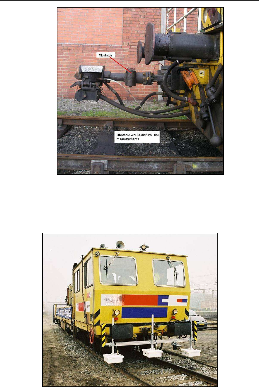
IDS Ingegneria Dei Sistemi S.p.A. Protocol: MN/2009/030 - Rev. 1.2
Safe Rail System Data Acquisition Software
63
/
76
Fig. A. 1 - No obstacle must be present between buffers
A typical installation of the system (3 antenna configuration) is shown in the following
picture (Fig. A. 2).
Fig. A. 2 - Example of a typical installation of the system
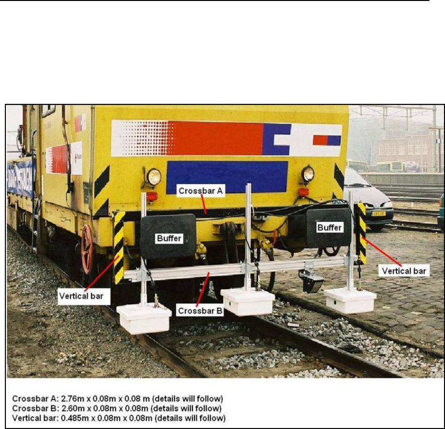
IDS Ingegneria Dei Sistemi S.p.A. Protocol: MN/2009/030 - Rev. 1.2
Safe Rail System Data Acquisition Software
64
/
76
A.3 - Specifications for the fixing frame
SNCF is kindly required to provide the fixing frame; this frame consists of 2
cross-bars and 2 vertical-bars, as shown in the picture
Fig. A. 3
). M aterial to be
used for the frame could be either aluminium or iron.
Fig. A. 3 - Overview of the fixing frame
Specifications for the brackets, the cross and the vertical bars are given in the
following pictures Fig. A. 4 and Fig. A. 5.
All
the bars have a square shape section, 80 mm x 80 mm.
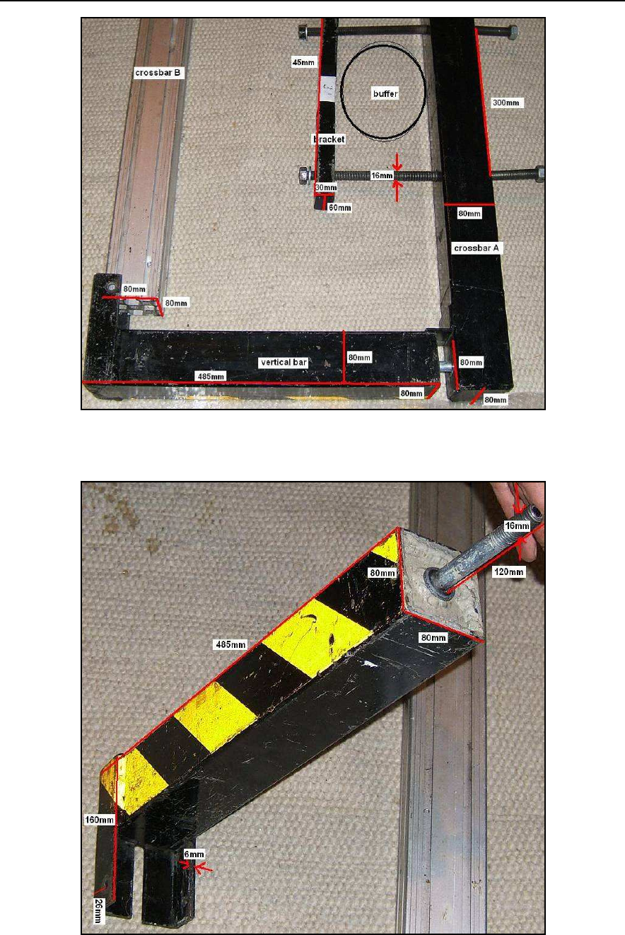
IDS Ingegneria Dei Sistemi S.p.A. Protocol: MN/2009/030 - Rev. 1.2
Safe Rail System Data Acquisition Software
65
/
76
Fig. A. 4 - Specifications for the cross-bars and the brackets
Fig. A. 5 - Specifications for the vertical-bars
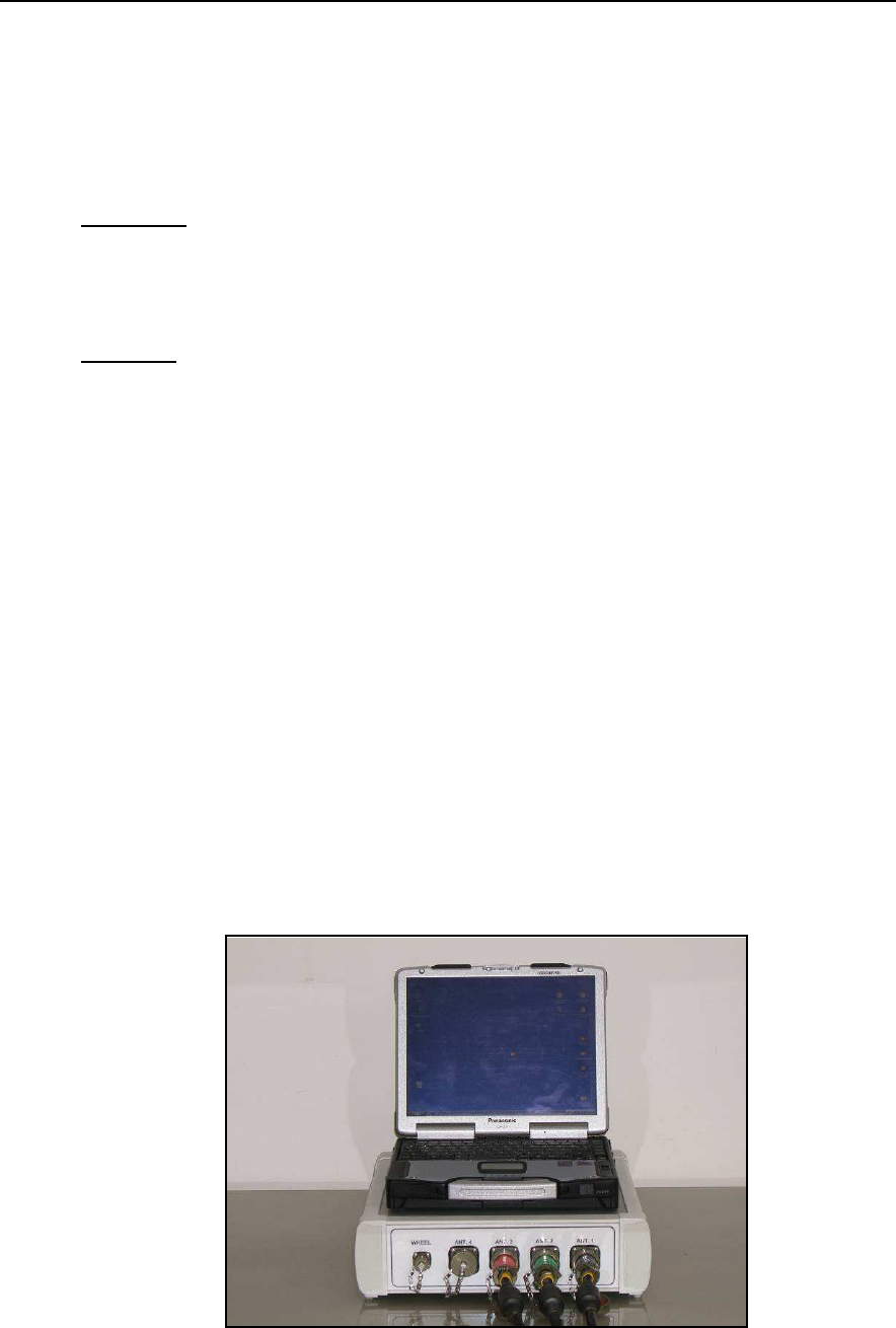
IDS Ingegneria Dei Sistemi S.p.A. Protocol: MN/2009/030 - Rev. 1.2
Safe Rail System Data Acquisition Software
66
/
76
APPENDIX B - SRS SYSTEM TECHNICAL SPECIFICATIONS
B.1 - SRS_PLUS System Technical Specifications
The SRS_PLUS system is only compatible with SRS_PLUS 400MHz
Hardware
SRS_PLU S Control Unit
Master Unit: IDS recommends the use of the
Panasonic CF30
notebook
computeras shown in picture
Fig. B. 1
.
Software
SRS
data acquisition software
B.1.1 SRS_PLUS Control Unit specifications
The technical specifications of the SRS_PLUS Control Unit are given below
Maximum number of acquisition channels:
4
Pulse Repetition Frequency:
400KHz
Range:
0-9999nsec. (recommended 90ns)
Number of Stacks:
1–32 768
Max number of scans/second:
>1000
Number of samples per scan:
128-8192(recommended 384/512)
Trigger options:
manual or timed
Communication interface with the Master Unit:
Ethernet
Data transmission speed:
100 Mbit/sec
Maximum dimensions of a single radar profile:
depends on the Hard
Disk capacity
GPS:
supported
Power supply:
12 Volt
Power consumption:
18 Watt
Water Proof:
IP65
Fig. B. 1 – SRS_PLUS Control Unit and CF-30 Notebook

IDS Ingegneria Dei Sistemi S.p.A. Protocol: MN/2009/030 - Rev. 1.2
Safe Rail System Data Acquisition Software
67
/
76
B.2 - SRS-FW400 System Technical Specifications
The SRS-FW400 system is only compatible with SRS-FW400 antennas.
Hardware
DAD FastWave Control Unit
Master Unit: IDS recommends the use of the
Panasonic CF30
notebook
computer as shown in picture
Fig. B. 1
.
Software
SRS
data acquisition software
B.2.1 Control Unit specifications
The technical specifications of the SRS-FW400 Control Unit are given below
Maximum number of acquisition channels:
4
Pulse Repetition Frequency:
100KHz
Range:
0-9999nsec. (recommended 90ns)
Number of Stacks:
1–32 768
Max number of scans/second:
>1000
Number of samples per scan:
128-8192(recommended 384/512)
Trigger options:
manual or timed
Communication interface with the Master Unit:
Ethernet
Data transmission speed:
100 Mbit/sec
Maximum dimensions of a single radar profile:
depends on the Hard
Disk capacity
GPS:
supported
Power supply:
12 Volt
Power consumption:
18 Watt
Water Proof:
IP65
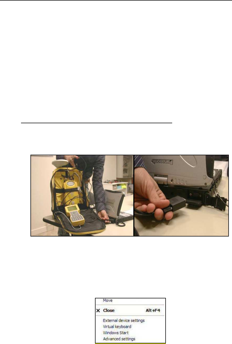
IDS Ingegneria Dei Sistemi S.p.A. Protocol: MN/2009/030 - Rev. 1.2
Safe Rail System Data Acquisition Software
68
/
76
APPENDIX C - USING GPS WITH THE SRS SYSTEM
The SRS system can acquire GPS data in NMEA$GGA format. You therefore
have to set the GPS receiver so that the data output through the serial port or
Ethernet port is in NM EA$GGA format
.
The serial or ethernet communication between the GPS and the
Panasonic CF-30
notebook computer must be set up for GPS as follows:
•
Baud rate: 9800;
•
Byte size: 8;
•
Parity: No;
•
Stop bits: 1.
GPS data acquisition procedure with the SRS_PLUS system
:
Step 1
Connect the GPS receiver to the
Panasonic
notebook computer using the
serial cable shown in pictures Fig. C. 1.
Fig. C. 1 - Connecting the GPS to the notebook computer
Step 2
Open the
External device settings
after having clicked on the SRS
software icon at the top left of the main window (see pictures Fig. C. 2 and
Fig. C. 3).
Fig. C. 2 - External device settings command
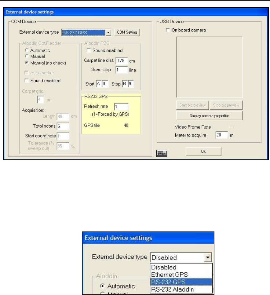
IDS Ingegneria Dei Sistemi S.p.A. Protocol: MN/2009/030 - Rev. 1.2
Safe Rail System Data Acquisition Software
69
/
76
Fig. C. 3 - External device settings window
Step 3
In the
External device settings
window, select the
External device type
(picture Fig. C. 4) field then select the type of GPS connection as
RS-232
GPS (serial port).
Fig. C. 4 - External device settings field
Step 4
Click the
COM Setting
button; this opens the window shown in picture
Fig. C. 5, from where you can set the parameters shown according to the
characteristics of the GPS being used.
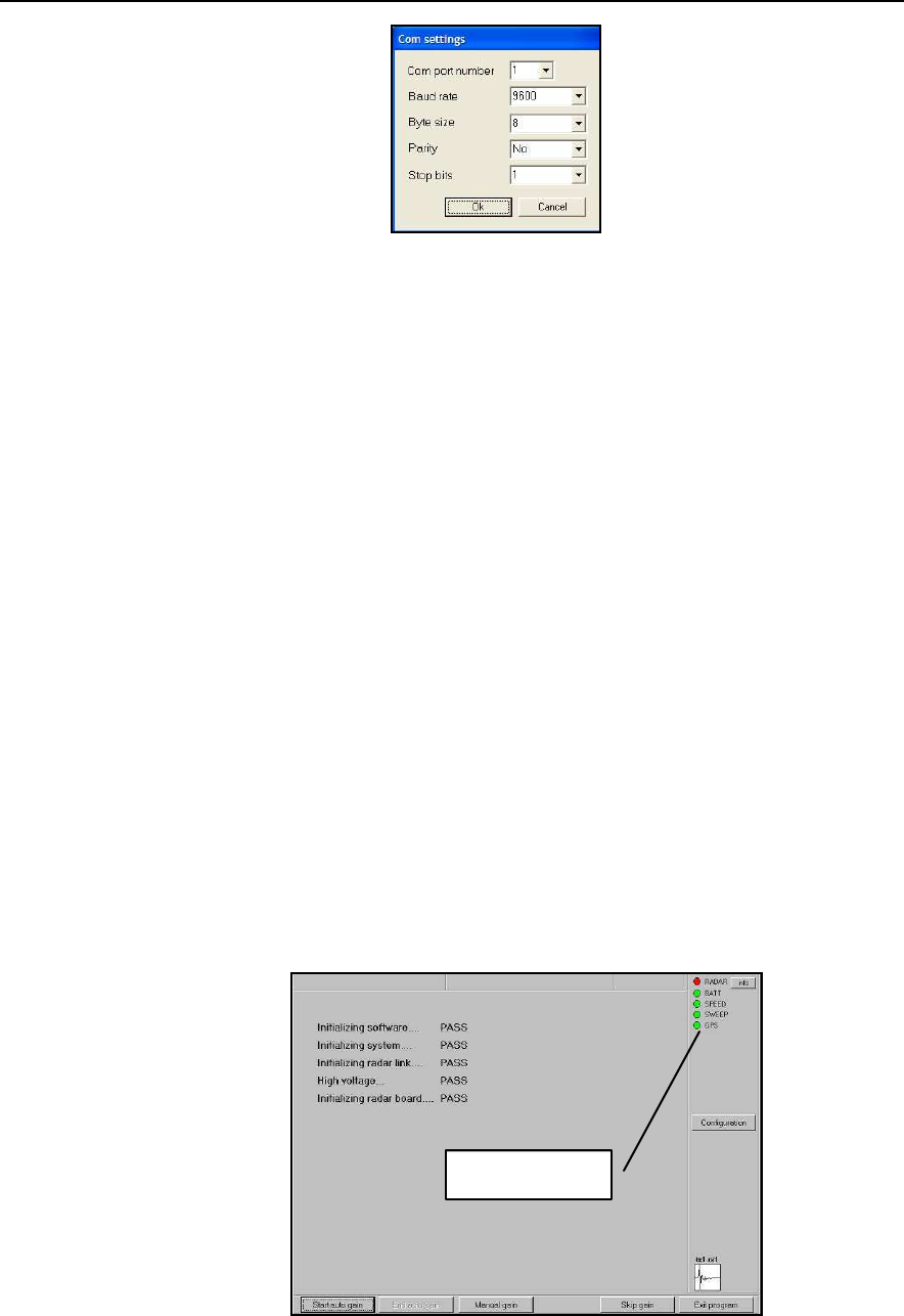
IDS Ingegneria Dei Sistemi S.p.A. Protocol: MN/2009/030 - Rev. 1.2
Safe Rail System Data Acquisition Software
70
/
76
Fig. C. 5 - Com settings window
For example, selecting External device type RS-232 GPS :
Select 1 in the
Com
menu (or set the number of the COM port
number the GPS is connected to) and the other parameters according
to the GPS characteristics;
Use the
Refresh rate
field in Fig. C. 3 to select the number of
sweeps interval the GPS data will be acquired with; for example, if
you have set the
Acquisition Step
to 2.4cm and the
Refresh rate
field to 20, the system will acquire GPS data every 48cm (2.4cm
*20=48cm); if the
Refresh rate
= 1, the SRS_PLUS system will
uptake all the information produced by the GPS according to the
time parameters set on GPS equipment.
Step 5
Accept the parameters set in the
COM settings
field by clicking the
OK
button, as shown Fig. C. 5.
Step 6
Correct functioning of the GPS and its communication with the
SRS_PLU S system is indicated by the GPS
spy light in the acquisition
window; when the light is green, the GPS is correctly connected and
functioning; when the GPS is red, either the connection between the GPS
and SRS_PLUS systems has not been correctly made or the GPS is
switched off (see picture Fig. C. 6).
Fig. C. 6 - GPS spy
GPS spy light
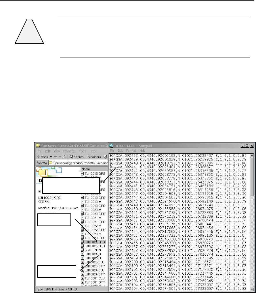
IDS Ingegneria Dei Sistemi S.p.A. Protocol: MN/2009/030 - Rev. 1.2
Safe Rail System Data Acquisition Software
71
/
76
!
WARNING
Remember that the GPS spy light only indicates the correct
functioning of the GPS, not the accuracy of the GPS readings; to
evaluate precision, use the tools supplied with the GPS system
Step 6
The GPS data in NMEA$GGA format are saved as an ASCII file in the
same directory as the radar data; the GPS files have the same numbering
as the radar files, but have a *.GPS extension (see the example shown in
the picture Fig. C. 7). During the radar data acquisition phase, you can
check the GPS acquisition data using white M arkers placed at the
bottom of the radar map.
Fig. C. 7 - Example of a GPS file
GPS fi
le
Radar file
GPS file format
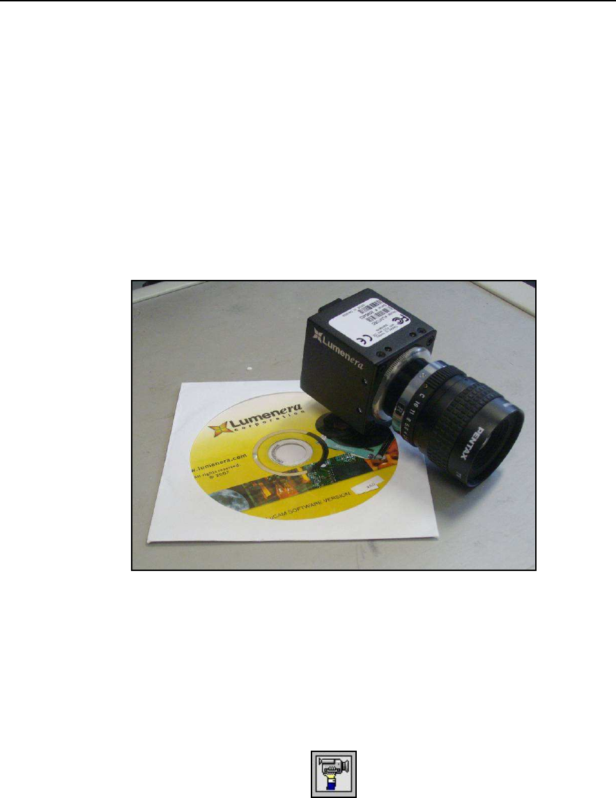
IDS Ingegneria Dei Sistemi S.p.A. Protocol: MN/2009/030 - Rev. 1.2
Safe Rail System Data Acquisition Software
72
/
76
APPENDIX D - USING CAMERA WITH THE SRS SYSTEM
The SRS system with Lumenera camera option, provided by IDS, has to be used
as following:
Step 1
Install the drivers of the camera in the acquisition PC launching the
dedicated CD-ROM for Lumenera camera, LM 135C model, having a
resolution of 800x600 pixels (see Fig. D. 1) pressing in sequence
Next/Continue Anyway
buttons. As you finish with success the installation,
reboot the PC. To install correctly the drivers, user has to be connected as
System Administrator.
Fig. D. 1 – Videocamera “Lumenera LM135C”
Step 2
Connect the camera to the PC through USB port and activate it. After
launching the SW SRS_PLUS, you will see the icon besides the spies in
the opening window, as shown in picture on the label of the manual (see
icon here below).
Step 3
Select
External device settings
after having clicked on the SRS software
icon at the top left of the main window (see Fig. D. 2 and Fig. D. 3).
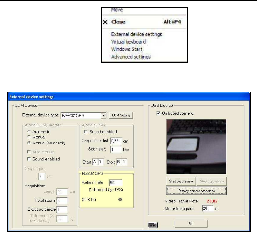
IDS Ingegneria Dei Sistemi S.p.A. Protocol: MN/2009/030 - Rev. 1.2
Safe Rail System Data Acquisition Software
73
/
76
Fig. D. 2 - External device settings command
Fig. D. 3 - External device settings window
Step 4
In Fig. D. 3 you can see the field USB Device, where you have to activate
the textbox
On board camera
.
Step 5
Here the user has to set the values of the following parameters related to
the camera images acquisition:
• Start/Stop big preview
: here the user can start/stop a zoom of the camera
preview.
• Display camera properties
: clicking this button before starting the
acquisition, the user can edit and set all the parameters of the camera in the
following window (
Fig. D. 4
). Here the user can set manually
o Exposure:
opening time of the camera shutter (also automatically by
clicking
Auto
option);
o Gain:
signal’s gain of the camera sensor (also automatically by
clicking
Auto
option);
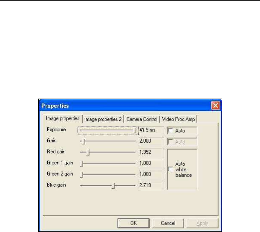
IDS Ingegneria Dei Sistemi S.p.A. Protocol: MN/2009/030 - Rev. 1.2
Safe Rail System Data Acquisition Software
74
/
76
o Red gain:
signal’s red colour gain of the camera sensor (also
automatically by clicking
Auto
option);
o Green 1 gain:
signal’s green 1 colour gain of the camera sensor (also
automatically by clicking
Auto white balance
option);
o Green 2 gain:
signal’s green 2 colour gain of the camera sensor (also
automatically by clicking
Auto white balance
option);
o Blue gain:
signal’s blue colour gain of the camera sensor (also
automatically by clicking
Auto white balance
option).
Fig. D. 4 – Camera properties
• Video Frame Rate
: it’s the speed with which the camera sends data to the PC;
it’s a parameter depending on the PC’s capability and it’s automatically set
during the acquisition.
• Meter to acquire
: it’s the distance (chosen by the user) between each saved
image
.
Step 6
Then press OK button in Fig. D. 3
.
Step 7
As the user will start acquisition, the
Camera View
window (shown in Fig.
D. 5) will appear on the screen, besides the radar section in progress with
the movement of the Safe Rail System.
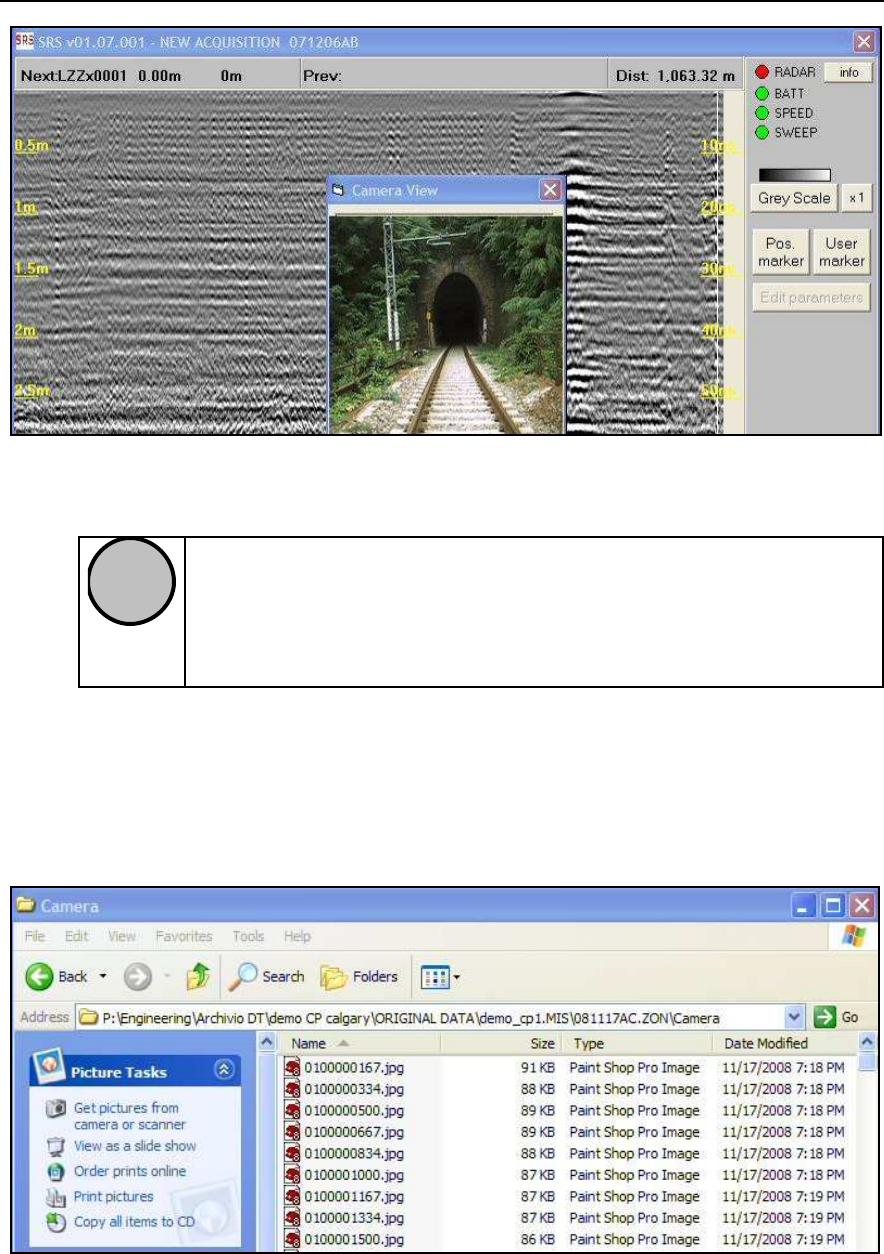
IDS Ingegneria Dei Sistemi S.p.A. Protocol: MN/2009/030 - Rev. 1.2
Safe Rail System Data Acquisition Software
75
/
76
Fig. D. 5 – Camera View window
!
NOTE
If the user starts acquisition while the camera is activated by software
(
On board camera
option is activated), but the camera
is physically
unplugged, SRS software informs the user with a proper message that
the camera is not working, and then
Camera View
window will be
closed automatically, without closing the whole software.
Step 8
After you finish the scan and press
End acquisition
button, the software
will create automatically a folder named “Camera” in the directory of the
mission just acquired (see Fig. D. 6). This folder contains “n” files .jpg for
“n” pictures acquired by the videocamera during the scan.
Fig. D. 6 – Folder “Camera”
IDS Ingegneria Dei Sistemi S.p.A. Protocol: MN/2009/030 - Rev. 1.2
Safe Rail System Data Acquisition Software
76
/
76
!
NOTE
1.
Make sure there is sufficient light into the camera (eg.
aperture is open as aperture controls the amount of light
entering camera) and exposure time in not set to 0 (you
can’t take a picture/video if exposure time is set to zero)
2.
When upgrading Lumenera software, ensure the follow
steps are followed:
a.
Unplug camera from USB
b.
Uninstall the Lucam software
c.
Reboot windows
d.
Download the latest Lucam software:
http://www.lumenera.com/support/download.php
e.
Install new Lucam software
f.
Reboot windows
g.
Plug camera back into the same USB port
h.
Try acquiring pictures/video from a bright source (eg
bright room)
i.
If there is no video, maybe it’s too dark due to wrong
software and hardware settings. Check 1. Ensure
software setting is correct to allow enough light into the
lens
j.
If camera still doesn’t work, try upgrading drivers from
‘Device manager’