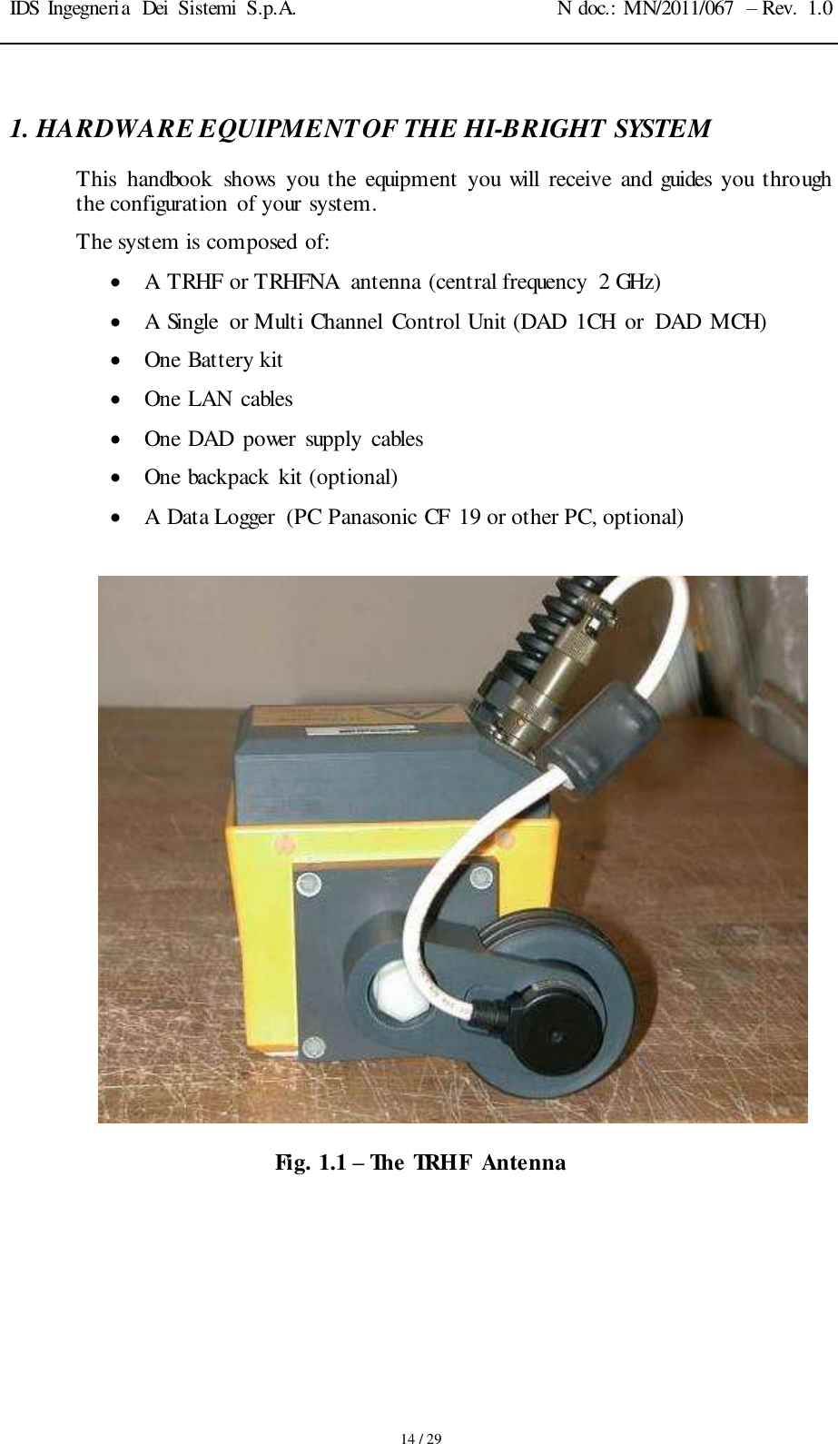
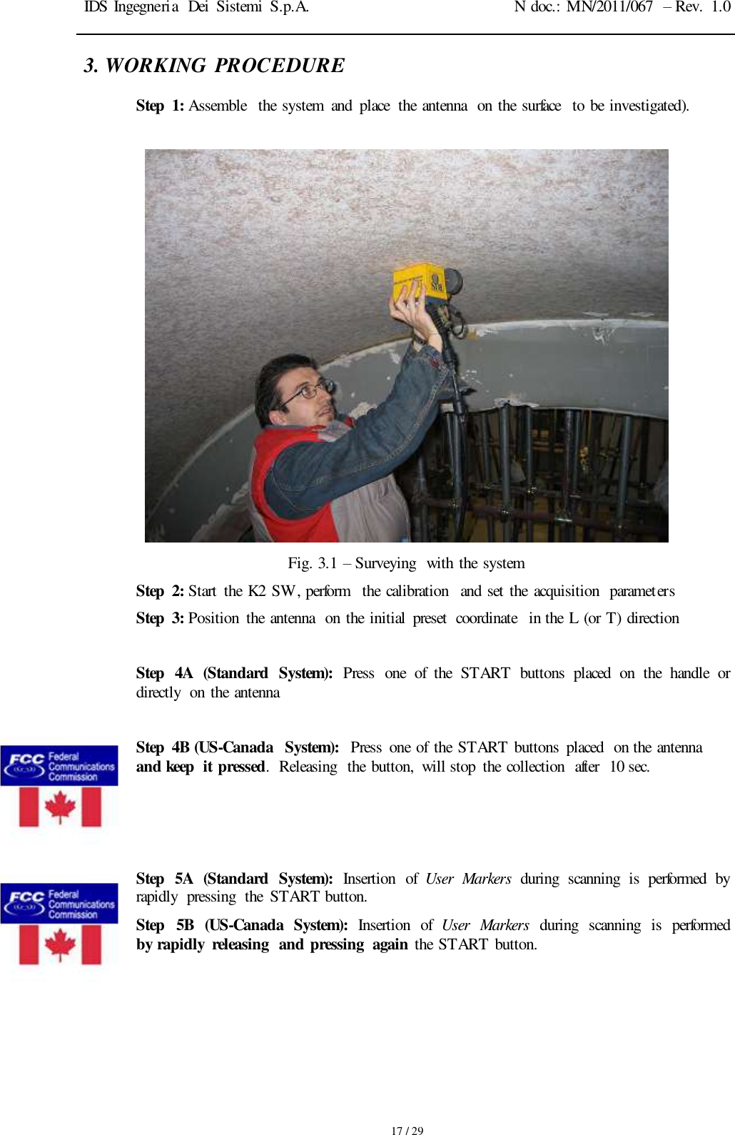
IDS GeoRadar s r l TRHFNA Ground Penetrating Radar User Manual manuale d uso

IDS Ingegneria dei Sistemi SpA Ground Penetrating Radar manuale d uso
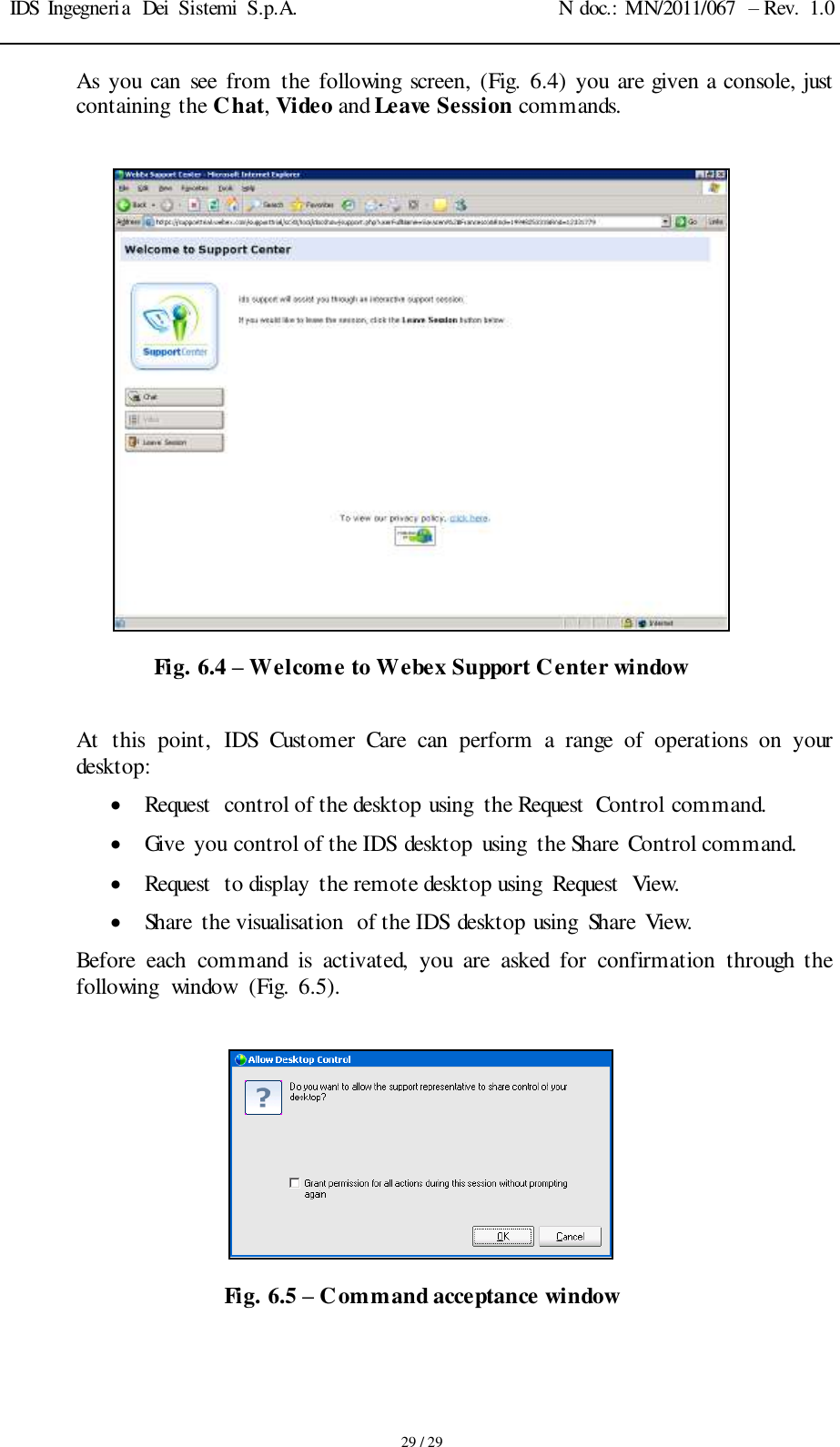
MN_2011_067_10_TRHF_HW_user manual_ENG final

  INGEGNERIA  DEI  SISTEMI S.p.A.   Rev.  1.0 N°doc.:  MN/2011/067  TRHF/TRHFNA Hardware Configuration User’s Guide           December 2011
IDS Ingegneria  Dei  Sistemi  S.p.A. N doc.: MN/2011/067  – Rev.  1.0     2 / 29 Document Evolution Revision Date Reason for modification Rev. 1.0 December  2011 First edition     OUR CONTACTS  IDS Ingegneria dei Sistemi S.p.A. – GeoRadar Division Via  Enrica  Calabresi,  24 56121 Montacchiello (PISA)  - ITALIA Fax: +39.050.3124 205 inforis@ids-spa.it  Customer Care department: customercare.gpr@ids-spa.it Tel.: +39.050.3124 355/356  Sales & Marketing department: sales.gpr@ids-spa.it Tel.: +39.050.3124 352
IDS Ingegneria  Dei  Sistemi  S.p.A. N doc.: MN/2011/067  – Rev.  1.0     3 / 29 DISCLAIMER  IDS  WILL  NOT  BE  HELD  RESPONSIBLE  FOR  THE  CONSEQUENCES  OF  AN IMPROPER  USE  OF THE EQUIPMENT  AND/OR  THE SOFTWARE.   THIS  SOFTWARE  MAY  INCLUDE  AUTOMATED  DATA  PROCESSING  AND ANALYSIS  TOOLS.   WHILE  EVERY  EFFORT  IS  MADE  TO  ENSURE  THE  ACCURACY  OF  THE INFORMATION  PROVIDED  BY  THOSE  TOOLS,  THEY  MUST  NOT  BE INTENDED  AS  A  SUBSTITUTE  FOR  INTELLIGENT  ANALYSIS;  RATHER,  THEY HAVE  TO  BE  INTENDED  AS  AN  ADVISOR  AND  THE  USER  MUST  NOT COMPLETELY  RELY  ON  THE  RESULTS  PROVIDED  BY  THEM  TO  GIVE  THE COMPLETE ANSWER. IDS  INGEGNERIA  DEI  SISTEMI  SPA  ASSUMES  NO  LIABILITY  FOR  ANY DIRECT,  INDIRECT,  SPECIAL,  INCIDENTAL  OR  CONSEQUENTIAL  DAMAGES OR  INJURIES  CAUSED  BY  SUCH  RELIANCE  ON  THE  ACCURACY, RELIABILITY,  OR  TIMELESS  OF  THE  INFORMATION  PROVIDED  BY  THOSE TOOLS. ANY  PERSON  OR  ENTITY  WHO  RELIES  ON  INFORMATION  OBTAINED  FROM THE  AUTOMATED  DATA  PROCESSING/ANALYSIS  TOOLS  ONLY,  DOES  SO  AT HIS  OR  HER  OWN RISK
IDS Ingegneria  Dei  Sistemi  S.p.A. N doc.: MN/2011/067  – Rev.  1.0     4 / 29 CONFORMITY TO EUROPEAN REGULATIONS  The  equipment  conforms  to  the  following  requirements  set  by  EC regulations,  including  subsequent  modifications,  and  to  the  legislation  set by the member  states that implement  these regulations:   1999/05/EEC Radio Directive Warning:  this  equipment  is  destined  for  use  in  industrial  environments (Class  A  apparatus).  In  residential,  commercial  and  light  industry environments,  this  apparatus  may  generate  radio  interference:  in  this  case, the  user  may  be  required  to  operate  while  taking  appropriate countermeasures. The  apparatus  is sensitive to the presence of external electromagnetic fields, which may reduce its performance.
IDS Ingegneria  Dei  Sistemi  S.p.A. N doc.: MN/2011/067  – Rev.  1.0     5 / 29    ! WARNING   CLEANING INFORMATION  Before  cleaning  any  external  parts  of  the  apparatus,  make  sure that  all  cables  have  been  disconnected,  including  the  power supply cable. If a damp cloth is used, make sure it is not too wet, to  avoid  any  damage  to  the  electrical  components  of  the equipment.  Wait  until  the  equipment  is  totally  dry  before reconnecting  the cables. The system should be cleaned periodically  using a damp cloth. Do not use solvents or abrasive detergents. Do  not  apply  liquid  directly  to  the  electrical  contacts  of  the various  connectors.  If  a  specific  spray  is  used  to  clean  the  PC TFT  monitor, make sure it is not flammable; ion any case, do not spray  it  directly on the screen, instead, spray it onto the cleaning cloth.
IDS Ingegneria  Dei  Sistemi  S.p.A. N doc.: MN/2011/067  – Rev.  1.0     6 / 29    BATTERIES REMOVAL INFORMATION  Laptop Batteries: Manufacturer:  PANASONIC Type: Li-ion  Ni Characteristics:  10.65V  5.7Ah Removal  instructions: 1. turn off the laptop; 2. open the drawer  with the symbol of the batteries; 3. extract  the battery pack pulling  the tab.   Radar batteries: Manufacturer:  FIAMM FG21202  / SAFT MP176065 Type: rechargeable  lead acid / rechargeable  lithium-ion Characteristics:  12V  & 12Ah / 15V  & 6.8Ah Removal  instructions: 1. disconnect the battery from  the instrument: a. pull the connector wings; b. separate the connectors; 2. remove the battery from  the cover (optional)  opening the strap.
IDS Ingegneria  Dei  Sistemi  S.p.A. N doc.: MN/2011/067  – Rev.  1.0     7 / 29     RECICLYING   The  crossed  out wheeled bin symbol shown on the equipment indicates that the  product  must  be  recycled  separately  from  other  waste  at  the  end  of  its useful life.  Separate  waste  disposal  of  this  product  at  the  end  of  its  useful  life  will  be organized  and  managed  by  IDS.  When  you  decide  to  dispose  of  the equipment,  contact  IDS and follow the system that IDS has set up to permit the separate collection  of the apparatus at its life  end.  Adequate  separate  collection  for  its  subsequent  recycling,  treatment  and environmental  friendly  disposal  contribute  towards  avoiding  any unnecessary  effects  on the environment and to health and favor the reuse or recycling  of  the  materials  that  make  up  the  equipment.  Unauthorized disposal  of  this  product  as  unsorted  waste  by  its  possessor  will  lead  to an administrative  penalty foreseen by national regulations.
IDS Ingegneria  Dei  Sistemi  S.p.A. N doc.: MN/2011/067  – Rev.  1.0     8 / 29 WARRANTY  CERTIFICATE  CONDITIONS 1) IDS  Ingegneria  dei  Sistemi  S.p.A,  hereinafter  referred  to  as  IDS,  warrants  hardware/software products for a period of  12 months from the delivery date to the original customer; 2) The delivery date is certified by the “ Warranty Registration Form”; 3) IDS’s  hardware  products  will  be  free  from  defects  in  materials  workmanship  under normal  use and service; 4) IDS’s obligation is limited to repairing or replacing parts or equipment which are returned to IDS, without  alteration  or  further  damage,  and  which  in  IDS  s  judgment,  were  defective  or  became defective  during normal use; 5) IDS’  software will  have  to be installed on a PC according to the requirement of the IDS hardware ( see IDS User’s Guide the Software  Data Acquisition); 6) IDS’  s  software products  designed  by  IDS  for use for IDS hardware products are warranted not to fail to  execute  their  programming  instructions  due  to  defects  during  the warranty  period,  provided they are  properly  installed on  IDS hardware products. IDS does not warrant if the IDS software will be used and operated  in hardware  and software combinations not selected by IDS; 7) IDS  does  not  assumes  any liability  for  any  direct,  indirect,  special,  incidental  or consequential damages  or injuries caused by  proper  or improper operation  of  its equipment  whether defective or not defective; 8) This  software  may  include  automated  data  processing and analysis  tools.  While  every  effort  is made to ensure the  accuracy of  the  information  provided  by those tools, they must not be intended as  a  substitute for  intelligent  analysis; rather,  they  have to be  intended as an advisor and the user must not completely rely on the results provided by them to give the complete answer. IDS assumes no liability for any direct, indirect special, incidental or consequential damages or injuries caused by such  reliance on  the  accuracy,  reliability,  or timeliness of  the  information provided by those tools. Any  person  or  entity  who  relies  on  information  obtained  from  the  automated  data processing/analysis tools only, does so at his or her own risk; 9) IDS’s warranty does not extend and shall not apply to: a) Products which have been repaired or altered  by other than IDS personnel; b) Products which have been subjected to misuse, neglect, accident or improper installation; c) Products  in  which  have  been  installed  Hardware/Software  accessories  not  supplied  by  IDS and/or without any approval by IDS; d) Products  which  have  been  connected  to  equipment  different  from  the  ones supplied  by  IDS (except  the PC data Logger which must conform to IDS specifications; e) Products which have been damaged  by natural disaster or calamities. 10) Before returning  any equipment to  IDS  ,  you  have to contact the IDS Customer Care Office that will authorize you to return the material to be repaired; 11)  Once  the  parts/equipment to  be repaired arrive to IDS, IDS may inspect the defective products to verify  they are  eligible  for repair  or replacement.  All packing  must  be saved for inspection purpose in  order  to  assist  IDS  to  understand  the cause  of  the defects. IDS, will not be obliged to repair, or replace  for  products  returned  as  defective  but  damaged  from  abuse, misuse,  negligence ,  accident loss or damage in transit; 12) The  final  clients,  is  responsible  for  ensuring  the  defective  products  returned  to  be  properly packaged; 13) The  above  warranty  are  sole  and  exclusive,  and  no  other warranty,  whether written  or  oral,  is expressed  or implied.
IDS Ingegneria  Dei  Sistemi  S.p.A. N doc.: MN/2011/067 – Rev.  1.0     9 / 29 IMPORTANT  NOTE  FOR THE  US CUSTOMERS FCC ID: UFW-TRHFNA This device complies with part 15 of the FCC Rules: Operation is subject to the following conditions: 1. This device may not cause harmful interference, and 2. This device must accept any interference received, Including interference that may cause undesired operation  Warning: Changes or modifications to this unit not expressly approved by the party responsible for compliance could void the user’s authority to operate the equipment. Operation of this device is restricted to law enforcement, fire and rescue officials, scientific research institutes, commercial mining companies, and construction companies. Operation by any other party is a violation of 47 U.S.C. § 301 and could subject the operator to serious legal penalties. Coordination Requirements. (a) UWB imaging systems require coordination through the FCC before the equipment may be used. The operator shall comply with any constraints on equipment usage resulting from this coordination. (b) The users of UWB imaging devices shall supply detailed operational areas to the FCC Office of Engineering and Technology  who  shall  coordinate  this  information  with  the  Federal  Government  through  the  National Telecommunications and Information Administration. The information provided by the UWB operator shall include the name, address and other pertinent contact information of the user, the desired geographical area of operation, and the FCC ID number and other nomenclature of the UWB device. This material shall be submitted to the following address: Frequency Coordination Branch., OET Federal Communications Commission 445 12th Street, SW Washington, D.C. 20554 ATTN: UWB Coordination (d) Users of authorized, coordinated UWB systems may transfer them to other qualified users and to different locations upon coordination of change of ownership or  location to the FCC and coordination with existing authorized operations. (e) The NTIA/FCC coordination report shall include any needed constraints that apply to day -to-day operations. Such constraints could specify prohibited areas of operations or areas located near authorized radio stations for which additional coordination is required before operation of the UWB equipment. If additional local coordination is required, a local coordination contact will be provided. (f) The coordination of routine UWB operations shall not take longer than 15 business days from the receipt of the coordination request by NTIA. Special temporary operations may be handled with an expedited turn -around time when circumstances warrant. The operation of UWB systems in emergency situations involving the safety of life or property may occur without coordination provided a notification procedure, similar to that contained in CFR47 Section 2.405(a)-(e), is followed by the UWB equipment user.  Notice: Use of this device as a wall imaging system is prohibited by FCC regulations.  According  to  the  FCC  Part  15  rules,  the  system  includes  a  manually  operated  switch (“dead-man  switch”)  that  causes  the  transmitter  to  cease  operation  within  10  seconds  of being  released  by the operator. The  use  of  this  switch  is  further  explained  in  this  manual;  specific  instructions  for operating a system sold  in the US  are identified  by the following  label
IDS Ingegneria  Dei  Sistemi  S.p.A. N doc.: MN/2011/067  – Rev.  1.0     10 / 29 IMPORTANT  NOTE  FOR THE  CANADIAN  CUSTOMERS IC Certification Number: IC:8991A – TRHFNA This device complies with the requirements of IC Standard RSS-220 This Ground Penetrating Radar Device shall be operated only when in contact with or within 1 m of the ground. This Ground Penetrating Radar Device shall be operated only by law enforcement agencies, scienti fic research institutes,  commercial  mining  companies,  construction  companies,  and  emergency  rescue  or  firefighting organizations. NOTE  IMPORTANTE  POUR LES  UTILISATEURS  CANADIENS Numéro de certification IC:8991A – HIBRIGHT Cet appareil est conforme aux exigences de la norme RSS IC-220 Cet équipement géoradar doit être utilisé que lorsqu’il est en contact ou à moins de 1 mètre du sol. Cet équipement géoradar doit être utilisé que par des organismes d'application de la loi, des instituts de recherche scientifique, des sociétés minières commerciales, des entreprises de construction et de secours d'urgence ou les organisations de lutte contre les incendies.  According  to  the  IC  Standard  RSS-220,  the  system  includes  a  manually operated  switch (“dead-man  switch”)  that  causes  the  transmitter  to  cease  operation within 10  seconds  of being  released  by the operator. The  use  of  this  switch  is  further  explained  in  this  manual;  specific  instructions  for operating a system sold  in Canada  are identified  by the following  label
IDS Ingegneria  Dei  Sistemi  S.p.A. N doc.: MN/2011/067  – Rev.  1.0     11 / 29  RADIO-FREQUENCY EXPOSURE COMPLIANCE   This product  operated is usually operated at least 1 m from  the operator.   Typical  power  density  levels  at  a  distance  of  1  m  or  greater  is  below  1 W/cm2  (0.01  W/m2)  which  are  far  below  the  levels  specified  by  the current regulations.   Thus,  this  product  pose  no  health  and  safety  risk  when  operated  in  the normal  manner  of intended use.  CONFORMITÉ D’EXPOSITION AUX FRÉQUENCES RADIO   Le produit doit être à au moins un mètre de l’utilisateur  lorsqu’en opération.   Le niveau de densité de puissance à une distance de 1 mètre et plus est de 1 W/cm2  (0.01  W/m2),  ce  qui  est  nettement  inférieur  aux  niveaux  spécifiés par la réglementation  en vigueur. Ainsi,  ce  produit  ne  représente  aucun  risque  pour  la  santé  et  la  sécurité lorsqu'il  est exploité  dans les conditions d'utilisation  prescrites.
IDS Ingegneria  Dei  Sistemi  S.p.A. N doc.: MN/2011/067  – Rev.  1.0     12 / 29   INDEX 1. Hardware equipment of the Hi-Bright system........................................................14 2. Setting The System Up ..............................................................................................15 3. Working  Procedure ..................................................................................................17 4. The DAD Control Unit ..............................................................................................19 5. The Notebook Computer...........................................................................................21 5.1 Panasonic Toughbook rugged tablet PC ............................................................21 5.2 Connecting the DAD Control Unit - Notebook Computer..................................23 5.3 Wireless connection ............................................................................................25 6. On line assistance .......................................................................................................27 6.1 Remote assistance using Webex Support Center ................................................27 6.1.1 How to use the Webex service.................................................................... 27  FIGURES  INDEX FIG. 1.2 – THE TRHF ANTENNA...................................................................................14 FIG. 2.1 – FIXED CONNECTION CABLE BETWEEN THE ANTENNA AND DAD 15 FIG. 2.2 – LAN CABLE....................................................................................................15 FIG. 2.3 – POWER CABLE..............................................................................................15 FIG. 2.4 – METRIC WHEEL CABLE..............................................................................16 FIG. 3.1 – SURVEYING WITH THE SYSTEM..............................................................17 FIG.  4.1 – DAD  SIDE  FAST  WAVE  WITH BATTERY  PORT, LAN PORT AND WIRELESS CONNECTOR ......................................................................................19 FIG.  4.2 – DAD  SIDE  FAST  WAVE  WITH CONNECTIONS  TO POSITION  SENSOR AND ANTENNAE ....................................................................................................20 FIG.  4.3 – EXAMPLE OF ANTENNA  WITH A 19 POLE CONNECTOR  AND POSSIBILITY OF A CASCADE CONNECTION...................................................20 FIG. 4.4 – 19-11 POLE ADAPTOR..................................................................................21 FIG. 5.1 – PANASONIC TOUGHBOOK CF-19 .............................................................22 FIG. 5.2 – LAN CABLE....................................................................................................23 FIG.  5.3 – LAN  CABLE  CONNECTION  BETWEEN  THE NOTEBOOK  COMPUTER AND THE DAD CONTROL UNIT..........................................................................23 FIG. 5.4 – BATTERY CABLE .........................................................................................24 FIG.  5.5 – CONNECTING  THE DAD  CONTROL  UNIT TO THE BATTERY  PACK AND SWITCHING ON BUTTON (RED COLOR) .................................................24 FIG. 5.6 – WIRELESS PORT TO BE ACTIVATED ON CF-19.....................................25 FIG. 5.7 – WIRELESS CONNECTION ON THE DAD ..................................................26
IDS Ingegneria  Dei  Sistemi  S.p.A. N doc.: MN/2011/067  – Rev.  1.0     13 / 29 FIG. 5.8 – CONFIGURATION FILE FOR WIRELESS CONNECTION .......................26 FIG. 6.1 – MAIL SENT BY IDS TO THE CLIENT ........................................................27 FIG. 6.2 – CLIENT DATA INSERTION FORM .............................................................28 FIG. 6.3 – WEBEX SET UP WINDOW ...........................................................................28 FIG. 6.4 – WELCOME TO WEBEX SUPPORT CENTER WINDOW ..........................29 FIG. 6.5 – COMMAND ACCEPTANCE WINDOW.......................................................29
IDS Ingegneria  Dei  Sistemi  S.p.A. N doc.: MN/2011/067  – Rev.  1.0     14 / 29 1. HARDWARE EQUIPMENT OF THE HI-BRIGHT SYSTEM This  handbook  shows  you  the  equipment  you  will  receive  and  guides  you  through the configuration of your system. The system is composed  of:   A TRHF or TRHFNA  antenna (central frequency  2 GHz)  A Single  or Multi Channel  Control Unit (DAD  1CH  or  DAD  MCH)  One Battery kit   One LAN  cables  One DAD  power  supply  cables  One backpack kit (optional)  A Data Logger  (PC Panasonic CF  19 or other PC, optional)   Fig. 1.1 – The TRHF  Antenna
IDS Ingegneria  Dei  Sistemi  S.p.A. N doc.: MN/2011/067  – Rev.  1.0     15 / 29 2. SETTING THE SYSTEM  UP The following  list contains  all the cables  and  how they  are  connected:    Fixed  connection  between  the antenna  and  DAD  (Fig. 2.1);    Fig. 2.1 – Fixed  connection  cable  between  the antenna  and  DAD   LAN  cable  connecting  the  PC  to  the  DAD  (Fig.  2.2);  connect  the  large  LAN connector  to  the  port  on  the  DAD  and  the  other  end  to  the  smaller  port  on  the back  of the  PC;  Fig. 2.2 – LAN  cable   Cable  connecting  the  battery  power  supply  to  the  DAD  (Fig.  2.3);  connect  the metallic  connector  to the DAD  and  the white  plastic  connector  to the battery.    Fig. 2.3 – Power  cable
IDS Ingegneria  Dei  Sistemi  S.p.A. N doc.: MN/2011/067  – Rev.  1.0     16 / 29   Metric  wheel  cable:  connect  the  cable  of  the  metric  wheel  to  the  WHEEL  port located  on the back  side of  the  antenna  (Fig. 2.4).   Fig. 2.4 – Metric  wheel  cable
IDS Ingegneria  Dei  Sistemi  S.p.A. N doc.: MN/2011/067  – Rev.  1.0     17 / 29 3. WORKING  PROCEDURE  Step  1: Assemble  the system  and  place  the antenna  on the surface  to be investigated).     Fig. 3.1 – Surveying  with the system Step  2: Start  the K2 SW, perform  the calibration  and set the  acquisition  parameters Step  3: Position  the antenna  on the initial  preset  coordinate  in the L (or T) direction    Step  4A  (Standard  System):  Press  one  of  the  START  buttons  placed  on  the  handle  or directly  on the antenna  Step  4B (US-Canada  System):  Press  one of  the START buttons  placed  on the antenna and keep  it pressed.  Releasing  the button,  will stop  the collection  after  10 sec.     Step  5A  (Standard  System):  Insertion  of  User  Markers  during  scanning  is  performed  by rapidly  pressing  the  START button.   Step  5B  (US-Canada  System):  Insertion  of  User  Markers  during  scanning  is  performed by rapidly  releasing  and pressing  again the START button.
IDS Ingegneria  Dei  Sistemi  S.p.A. N doc.: MN/2011/067  – Rev.  1.0     18 / 29 Step  6A  (Standard  System):  The  scan  is  STOPPED  by  keeping  the  START  button pressed Step  6B (US-Canada  System):  The scan  is STOPPED  by releasing  the START button
IDS Ingegneria  Dei  Sistemi  S.p.A. N doc.: MN/2011/067  – Rev.  1.0     19 / 29 4. THE DAD CONTROL UNIT  The  DAD  Control  Unit  is  the  control  unit  responsible  for  directing  the antennas and digitalising  the acquired  radar  data. The DAD Control  Unit has the following  ports  Lan Port for a network connection to the Notebook Computer  Battery  Port  to connect the battery   Wheel Port   to connect the position sensor wheel  Ant.1/CHAINE  - Ant.2  for radar  antenna connection   Power  switch  with  pilot light    Wireless  antenna  connector    -  Fi g. 4.1 – DAD  side Fast Wave with Battery Port, Lan Port and wireless connector  LAN  port Battery  Port Start up button  Wireless antenna connector Wireless plug
IDS Ingegneria  Dei  Sistemi  S.p.A. N doc.: MN/2011/067  – Rev.  1.0     20 / 29  Fig. 4.2 – DAD  side Fast Wave with connections to position sensor and antennae  Considering  the  type  of  available  antenna,  the  following  combinations  are possible:   1. Ant.1  (connector  with  19 poles) This  kind  of  connector  may  be  connected  to  the  following  categories  of radar  antennae.   Entire  range of  TR  IDS  antennae  that has a 19 pole connector and foresee  a  cascade  connection,  Fig.  2-3  shows  an  example  of  a  an antennae with a 19 pole connector with  a cascade  connection.    Fig. 4.3 – Example of antenna with a 19 pole connector and possibility of a cascade connection  Ant1 and  Ant 2 Connectors Wheel Port For DAD connection  or toward  another antenna To connect  the other  antenna
IDS Ingegneria  Dei  Sistemi  S.p.A. N doc.: MN/2011/067  – Rev.  1.0     21 / 29  Entire range of TR IDS antennae that have an 11 pole connector, if supplied  with an appropriate 19-11 pole adaptor (Fig.  4.4).   Fig. 4.4 – 19-11 pole Adaptor  2. Ant.2  (11 pole connector) This  kind  of  connector  may  have  the  following  antenna  radar categories connected  Entire  range  of    mono  static  TR  IDS  antennae  with  an  11  pole connector   Entire  range  of  TR  IDS  antennae  with  internal  or  external multiplex and an 11 pole connector  5. THE NOTEBOOK COMPUTER IDS  acquisition  SW  is  usually  installed  on  a  Notebook  Computer.  Our  SW  is dedicated  to the specific phases  of setting up, acquiring  and saving  radar data. IDS  recommends to use one of the following  laptop: 5.1 Panasonic  Toughbook rugged tablet PC The Panasonic Toughbook  CF-19 PC (Fig.  5.1), has the following  characteristics:  CPU: 1.6GHz  Intel Core Duo.  Operating System: Windows  XP Professional  SP2.  RAM/Expandable to: 512MB SDRAM  (DDR2)/4GB  Hard  Drive/Speed:  80GB  shock-proof  (mounted  on  a  gel  support  or equivalent).  Optical  Drive:  2.4X DVD+R  DL  Display  Resolution:  10.4 inches/1024 x 768
IDS Ingegneria  Dei  Sistemi  S.p.A. N doc.: MN/2011/067  – Rev.  1.0     22 / 29  Graphics/Video  Memory:  Intel  945GM  video  accelerator  with  up  to 128MB shared  video  memory  Wireless  Networking:  WLAN  802.11a/b/g,  Bluetooth  2.0,  Optional WWAN (EVDO,  HSDPA)  and GPS  Ports:  Two  USB  2.0,  Firewire,  Ethernet,  modem, headphone, mic, docking connector  Card  Slots: PC Card  Type II, SD  Card  slot  Weight:  5 pounds  Size:  10.7 x 8.5 x 1.9 inches  Warranty/Support:  Three-year  limited  warranty,  parts  and  labor  lifetime toll-free 24/7.  Battery  Life  (Wi-Fi On/Off):  5h / 6h about  Environmental:  Water-proof (IP54)   Fig. 5.1 – Panasonic Toughbook CF-19   ! NOTE  No  communication  software  of  the  type  Firewall,  WiFi  or Antivirus  protection  may  be installed on the computer; these types of SW enter into conflict with  the acquisition  SW. IDS  takes  no  responsibility  for  any  functional  conflicts  that  may occur  between  their  own  software  and  any  other  software  installed by  the  user  onto  the  Notebook  Computer.  IDS  doesn’t  guarantee that  equipment  performance  will  be  maintained  using configurations  different  from those recommended.
IDS Ingegneria  Dei  Sistemi  S.p.A. N doc.: MN/2011/067  – Rev.  1.0     23 / 29 5.2 Connecting the DAD Control Unit - Notebook Computer The  following  describes  how  to cable  the  DAD  Control  Unit  to the  Notebook Computer   Use  the  Lan  Cable  (Fig.  5.2)  to  connect  the  DAD  Control Unit  and  the Notebook Computer  as shown  in (Fig.  5.3)    Fig. 5.2 – Lan Cable     Fig. 5.3 – Lan Cable connection between the Notebook Computer and the DAD Control Unit    Connect  the  DAD  Control  Unit  to  the  Battery  using  the  Battery  Cable  (Fig.  5.4) as shown  in (Fig.  5.5)
IDS Ingegneria  Dei  Sistemi  S.p.A. N doc.: MN/2011/067  – Rev.  1.0     24 / 29  Fig. 5.4 – Battery Cable   Fig. 5.5 – Connecting the DAD Control Unit to the battery pack and switching on button (red color)  Press  the red  button  to switch on the DAD control unit (Fig. 5.5). This button has to  be  kept  pressed  until the blue on switch lights up. If the K2_FW software is not activated  within 30  seconds,  the  indicator  light  will  start  to  flash.  As  soon  as  the K2_FW  software  is  activated  the  indicator  light  stops  flashing  and  appears  a constant  blue  light.  If,  however,  the  Software  is  not  activated  within  about  2 minutes  30  seconds,  the  DAD  unit  will  automatically  shut  down.  Once  the K2_FW software  has  been  shut  down,  the  indicator  will flash for about 30 seconds and will  automatically shut down  after 2 minutes.    !  WARNING   DON’T  CONNECT  the  Battery Cable  to the  Remote  connector found  on  IDS  TR  antenna;  IDS  declines  any  responsibility  for damage  caused  to the system due to erroneous connections.
IDS Ingegneria  Dei  Sistemi  S.p.A. N doc.: MN/2011/067  – Rev.  1.0     25 / 29 5.3 Wireless connection Here below  you  can  see  the  requirements  and steps to connect by wireless DAD to PC: 1) System  requirement:  wireless  network  board  of  PC  must  support network protocol type 802.11g. 2) Disconnect  Lan cable from DAD and  from PC. 3) Connect  the  wireless  plug  on  LAN  port  of  the DAD  (Fig. 4.1  e  Fig. 5.7). 4) Activate  wireless  network  on  PC  choosing  “ON”  with  the  button  on relative port shown  in Fig.  5.6. 5) Set  up  wireless  board  on  PC  with  the  following  IP  address: 192.168.200.195. 6) Disable  all  boards  present  within  “network  connections”  window  on PC. 7) Switch  off PC and reboot operating system. 8) Enable wireless  board. 9) Switch  on the DAD. 10) Wait for signal  on PC of activating connection RIS  K2. 11) Launch  the  acquisition  software  icon  setting  up  a  Wi-Fi  configuration file: you can recognize  them from the label “WiFi” (see  Fig. 5.8).   Fig. 5.6 – Wireless port to be activated on CF-19  WIRELESS ON
IDS Ingegneria  Dei  Sistemi  S.p.A. N doc.: MN/2011/067  – Rev.  1.0     26 / 29    Fig. 5.7 – Wireless connection on the DAD   Fig. 5.8 – Configuration file for wireless connection
IDS Ingegneria  Dei  Sistemi  S.p.A. N doc.: MN/2011/067  – Rev.  1.0     27 / 29 6. ON LINE ASSISTANCE 6.1 Remote assistance  using Webex Support Center Webex  Support  Center is a service that allows the activation of a two host session, making  an  application  or  the  desktop  available  to  the  other  user  or  letting  you capture another remote desktop. It can be used  to perform web  conferences  and presentations. It is easy  to use thanks to its simple and intuitive interface. Since  there  are  no  firewalls  or  other types  of  network  configurations,  it  is  a fast and  secure  means  of  reaching  any client host in any part of the world. In fact, the client  only  has  to  accept  to  download  a  small  plug  used  to  permit  the  service authentication and functioning.  6.1.1 How  to use the Webex  service   You  will  receive  an  email  from  IDS  Customer  Care  containing  a  link  to  the support session  (see Fig.  6.1).   Fig. 6.1 – Mail sent by IDS to the client
IDS Ingegneria  Dei  Sistemi  S.p.A. N doc.: MN/2011/067  – Rev.  1.0     28 / 29 Once  you  have  clicked  on  the  link  sent  by  email,  the  following  window  will appear. Insert your data into the form (see Fig.  6.2).   Fig. 6.2 – Client data insertion form   Once  you  have  clicked  Submit,  the  following  page  will  appear showing  a downloading  bar.  The  session  starts  as  soon as  the  download  is complete. (see  Fig. 6.3).  Fig. 6.3 – Webex Set up window
IDS Ingegneria  Dei  Sistemi  S.p.A. N doc.: MN/2011/067  – Rev.  1.0     29 / 29 As  you  can  see  from  the  following  screen,  (Fig.  6.4)  you  are given a console, just containing  the Chat, Video and Leave Session commands.   Fig. 6.4 – Welcome to Webex Support Center window  At  this  point,  IDS  Customer  Care  can  perform  a  range  of  operations  on  your desktop:  Request  control of the desktop using  the Request  Control command.  Give  you control of the IDS  desktop  using  the Share  Control command.  Request  to display the remote desktop using  Request  View.  Share  the visualisation  of the IDS  desktop using  Share  View. Before  each  command  is  activated,  you  are  asked  for  confirmation  through  the following  window  (Fig.  6.5).   Fig. 6.5 – Command acceptance window

Navigation menu