IDT Technology RTGR328N-01 Remote Thermo-Hygro Sensor w/ RF Clock (433MHz Tx) User Manual MODEL RA313PA
IDT Technology Limited Remote Thermo-Hygro Sensor w/ RF Clock (433MHz Tx) MODEL RA313PA
User Manual
Weather Station
Model: BAR990HG
USER MANUAL
INTRODUCTION
Thank you for selecting the Oregon ScientificTM
Weather Station.
NOTE Please keep this manual handy as you
use your new product. It contains practical step-
by-step instructions, as well as technical
specifications and warnings you should know
about.
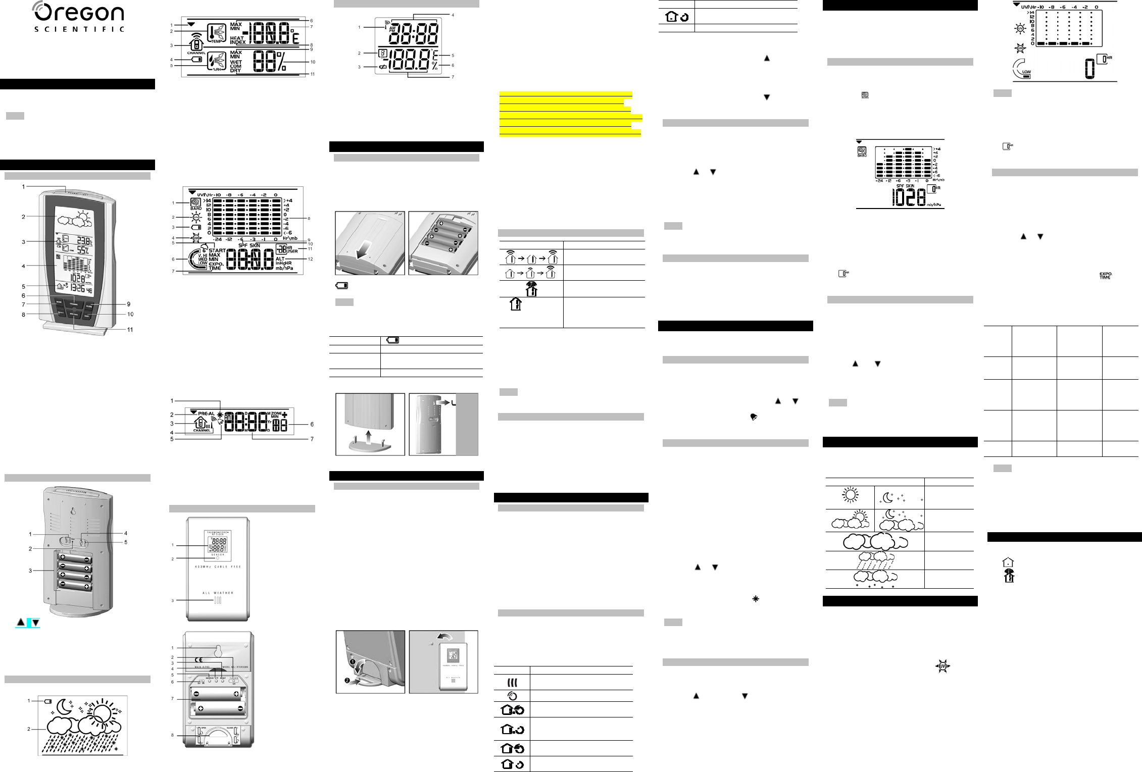
OVERVIEW
FRONT VIEW / LCD DISPLAY
1. SNOOZE / LIGHT: Activate 8-minute
snooze or backlight
2. Weather Forecast Area
3. Temperature, Humidity and Comfort Zone
Area
4. UVI and Barometer Area
5. Clock Area
6. CHANNEL: Switch remote sensor display
7. MODE: Change settings / display
8. SELECT: Switch areas
9. ALARM: View alarm status; set alarm
10. HIST: View historical barometer and UV
readings
11. MIN/MAX: View current, maximum and
minimum temperature / humidity / UV
readings
BACK VIEW
1. / Adjust settings; activate / deactivate
clock reception
2. RESET: Reset the unit
3. Battery compartment
4. °C / °F: Select temperature unit
5. mb / Hg: select pressure unit
LCD
Weather Forecast Area
1. Main unit battery low
2. Weather Forecast
Temperature and Humidity Area
1. Selected Area icon
2. Temperature trend
3. Channel number (1-5) / reception status
4. Low battery icon for remote sensor
5. Humidity trend
6. MAX / MIN temperature
7. Temperature - °C / °F
8. Heat Index
9. MAX / MIN humidity
10. Humidity
11. Humidity Comfort levels
UVI / Barometer Area
1. Barometric pressure is showing
2. UV is showing
3. Low battery icon for UV sensor
4. UVI value is showing
5. UV exposure time countdown has started.
6. UV index level
7. UV exposure time for user
8. Barometer / UV chart
9. SPF applied to user for UV exposure
10. User skin type for UV exposure
11. User no. (for UV Mode) or hour history for
UV / Barometric pressure reading
12. Altitude / barometric pressure / UVI
reading
Clock Area
1. Pre-Alarm is set
2. Pre-Alarm display / Pre-Alarm setting
3. Channel with clock reception is locked
4. Clock reception icon
5. Daily Alarm is set
6. Offset time-zone
7. Time / date / calendar
REMOTE SENSOR
1. LCD display
2. LED status
indicator
3. Ventilation
duct
1. Wall mount
2. CHANNEL:
select sensor
channel
3. RESET
4. °C / °F: select
temperature
unit
5. SEARCH:
search for
clock reception
6. EU / UK: select
clock signal
7. Battery
compartment
8. Stand
REMOTE SENSOR LCD
1. Signal reception
2. Channel number
3. Low battery icon
4. Time
5. Temperature unit (°C or °F)
6. Humidity %
7. Temperature / Humidity
GETTING STARTED
BATTERIES
Insert batteries before first use, matching the
polarity as shown in the battery compartment.
For best results, install batteries in the remote
sensor before the main unit. Press RESET after
each battery change.
indicates main unit batteries are low.
NOTE Do not use rechargeable batteries. We
recommend that you use alkaline batteries with
this product for longer usage and lithium
batteries in temperatures below freezing
UNIT LOCATION
Main Weather Forecast Area
Remote
sensor Temperature, Humidity and
Comfort Zone Area
UV sensor UVI and Barometer Area
Stand / Wall Mount:
REMOTE SENSOR
SET UP SENSOR
The main unit can collect data from up to 5
Thermo / Hygro Sensors and 1 UV Sensor.
(Additional sensors are sold separately. Contact
your local stockist for more information.)
To set up the thermo-hygro sensor:
1. Open the battery compartment with a small
Phillips screwdriver.
2. Insert the batteries.
3. Slide CHANNEL on the sensor to select a
channel. Make sure you use a different
channel for each sensor.
4. Slide EU / UK to your location.
5. Press RESET.
6. Close the battery compartment.
7. Secure the sensor in the desired location
using the table stand or wall mount.
For best results:
• Place the sensor out of direct sunlight and
moisture.
• Do not place the sensor more than 30 m (100
ft) from the main (indoor) unit.
• Position the sensor so that it faces the main
(indoor) unit, minimizing obstructions such as
doors, walls, and furniture.
• Place the sensor in a location with a clear
view to the sky, away from metallic or
electronic objects.
• Position the sensor close to the main unit
during cold winter months as below-freezing
temperatures may affect battery performance
and signal transmission.
The transmission range may vary depending on
many factors. You may need to experiment with
various locations to get the best results.
Standard Alkaline batteries contain significant
amounts of water. Because of this they will
freeze in low temperatures of approximately -
12°C (10°F). Disposable Lithium batteries have a
much lower threshold for temperature with an
estimated freezing range of below -30°C (-22°F).
Wireless ranges can be impacted by a variety of
factors such as extremely cold temperatures.
Extreme cold may temporarily reduce the
effective range between the sensor and the base
station. If the unit's performance fails due to low
temperature, the unit will resume proper
functioning as the temperature rises to within the
normal temperature range (i.e. no permanent
damage will occur to the unit due to low
temperatures).
SENSOR DATA TRANSMISSION
ICON DESCRIPTION
Main unit is searching
for the sensor(s)
A channel has been
found
Sensor 1 is sending
data
and “- - . -“
(Temperature /
Humidity display)
The sensor cannot be
found. Search for the
sensor or check
batteries
To search for a sensor:
1. Press SELECT to navigate to the
Temperature, Humidity and Comfort Zone
Area.
2. Simultaneously, press and hold MEM and CH
for 2 seconds.
NOTE If the sensor is still not found, check the
batteries, obstructions, and remote unit location.
UV SENSOR (OPTIONAL)
Refer to the UV sensor User Manual for
information on set-up.
To search for a UV sensor:
1. Press SELECT to navigate to UVI and
Barometer Area.
2. Simultaneously, press and hold MEM and CH
for 2 seconds.
CLOCK
CLOCK RECEPTION
This product is designed to synchronize its
calendar and clock automatically. The sensor
collects the data and transmits them to the main
unit once it is brought within range of a radio
signal:
• DCF-77 generated from Frankfurt, Germany
for Central Europe.
• MSF-60 generated from Rugby, England.
The radio signal range is 1500km (932 miles).
CLOCK RECEPTION SIGNAL
Initial reception takes 2-10 minutes for first set
up or when RESET is pressed. Once complete,
the reception icon will stop blinking. If the signal
is weak, it can take up to 24 hours to get a valid
signal.
ICON DESCRIPTION
Connection between main unit
and sensor collecting signals
Sensor signal reception
Main unit has contacted
sensor; time is synchronised
Main unit has contacted
sensor; time is not
synchronised
Main unit has lost contact with
sensor; time is synchronised
Main unit has lost contact with
sensor
;
time is not
synchronised
Main unit cannot contact
sensor
No icon Clock reception disabled
To enable clock signal reception:
1. Press SELECT to navigate to the Clock Area.
2. In clock mode, Press and hold for two
seconds.
To disable clock signal reception:
1. Press SELECT to navigate to the Clock Area.
2. In clock mode, Press and hold for two
seconds.
SET CLOCK
You only need to do this if you have disabled the
clock signal reception or are out of range.
1. Press SELECT to navigate to the Clock Area.
2. Press and hold MODE for 2 seconds.
3. Press or to change the setting.
4. Press MODE to confirm.
5. The setting order is: time zone offset hour (+ /
-23 hours),12 / 24 hour format, hour, minute,
year, date / month format, month, date and
display language.
NOTE The language options are (E) English,
(F) French, (D) German, (I) Italian, and (S)
Spanish.
DISPLAY
Press SELECT to navigate to the Clock Area,
then press MODE to toggle display between:
• Clock with seconds
• Clock with day
• Clock with time-zone
• Calendar
ALARM
This product has 2 alarms: The daily alarm and a
pre-alarm for snowy weather.
SET DAILY ALARM
1. Press SELECT to navigate to the Clock Area.
2. Press ALARM to enter alarm mode, AL will
appear.
3. Press and hold ALARM for 2 seconds.
4. Select the hour and minute. Press or to
change settings.
5. Press ALARM to confirm. indicates the
daily alarm is set.
SET PRE-ALARM
The pre-alarm activates a set time before the
daily alarm. It will only sound if the recorded
temperature from Channel 1 Sensor falls to 2°C
(35.6°F) or below.
For example, if you set the daily alarm to 7:00
AM, and the pre-alarm to 45 minutes, the pre-
alarm will sound at 6:15 AM provided the
outdoor temperature at Channel 1 Sensor is 2°C
or below.
1. Set up and activate the daily alarm.
2. Press ALARM to switch to pre-alarm view,
PRE-AL will appear.
3. Press and hold ALARM for 2 seconds.
4. Press or to select 15, 30, 45 or 60
minutes.
5. The pre-alarm is automatically activated when
you select a time.
6. Press ALARM to confirm. indicates the
pre-alarm is set
NOTE The daily alarm will NOT function until the
next day if the pre-alarm has been triggered.
Also, if you deactivate the daily alarm, the pre-
alarm is automatically deactivated.
ACTIVATE / DEACTIVATE ALARMS
1. Press SELECT to navigate to the Clock Area,
then press ALARM to select the daily or pre-
alarm.
2. Press to activate or to deactivate the
alarm.
To silence the alarm:
• Press SNOOZE / LIGHT to silence it for 8
minutes.
OR
• Press any other key to turn the alarm off and
activate it again after 24 hours.
BAROMETER
This product tracks fluctuations in barometric
pressure to provide the weather forecast, and
the current and past 24 hours barometric
pressure history measurements are recorded by
the main (indoor) unit.
VIEW BAROMETER DATA
1. Press SELECT to navigate to the UVI /
Barometer Area.
2. Press MODE to toggle UVI / Barometer
display. indicates barometer information is
displayed.
3. The bar chart display shows atmospheric
changes over the past 24 hours. The lower
display shows the current or historical
reading.
To select the unit of measurement:
Press mb / inHg.
To view barometer history:
1. Press SELECT to navigate to the UVI /
Barometer Area.
2. Press HIST to scroll through saved records.
shows how long ago the measurement
was taken.
SET ALTITUDE
To ensure barometric readings are reliable set
the altitude to reflect distance from sea level at
your position.
1. Press SELECT to navigate to the UVI /
Barometer Area.
2. Press and hold HIST for 2 seconds.
3. Use and to set the altitude in 10 M (33
ft) increments from -100 m (-328 ft) to 2500 m
(8202 ft).
4. Press HIST to confirm.
NOTE The maximum operating altitude for the
barometer and weather forecast is 2500m (8202
ft).
WEATHER FORECAST
This product forecasts the next 12 to 24 hours of
weather within a 30-50 km (19-31 mile) radius
based on barometric pressure trend readings.
ICON DESCRIPTION
Clear
(Day / Night)
Partially
Cloudy
(Day / Night)
Cloudy
Rainy
Snowy
UV MEASUREMENT
UV data is shown in the same area as the
Barometer. To view UV data please purchase a
compatible UV Sensor (ask your retailer for
further information).
1. Press SELECT to navigate to the UVI /
Barometer Area.
2. Press MODE to display UV data.
indicates UV data is displayed.
3. The bar chart display shows UV Index
changes over the past 24 hours. The lower
display shows the current or historical
reading.
NOTE Refer to the UV sensor User Manual for
information.
To view UVI history:
3. Press SELECT to navigate to the UVI /
Barometer Area.
4. Press HIST to scroll through saved records.
shows how long ago the measurement
was taken.
UV EXPOSURE TIME COUNTDOWN
To set the exposure time countdown you need
set to the Skin Type and Sun Protection Factor
(SPF) as follows:
1. In UVI display, press CHANNEL to select
user 1-4.
2. Press and hold MODE for 2 seconds.
3. Press or to enter the setting.
4. Press MODE to confirm.
5. The settings order is: skin type, SPF (sun
protection factor used), countdown activated /
deactivated.
6. Once the countdown is activated will
flash and the time remaining will appear.
7. When the countdown has reached "0", an
alarm will sound for 2 minutes. Press any
button to turn the alarm off. The icon will flash
for 2 minutes.
SKIN
TYPE TANS /
BURNS SKIN
COLOUR IN
UNEXPOSED
AREA
EYE
COLOUR
1 Never tans;
always burns Pale or milky
white;
alabaster
Blue
2 Sometimes
tans;
usually burns
Very light
brown;
sometimes
freckles
Blue /
Green
3 Usually tans;
sometimes
burns
Light tan,
brown or olive;
distinctly
pigmented
Gray /
Brown
4 Always tans;
rarely burns Brown, dark
brown or black Brown
NOTE Due to the many other factors that may
influence the emission of and your tolerance to
UV radiation, you are advised to consult your
doctor or dermatologist before engaging in any
activity involving extended exposures to UV rays
and Oregon Scientific is not responsible for any
results or consequences of relying on the
product’s suggestions.
TEMPERATURE AND HUMIDITY
The sensor reception icon indicates the
temperature data displayed:
• for indoor temperature
• for outdoor temperature (number
indicates the sensor channel displayed)
Press SELECT to navigate to the Temperature
and Humidity Area.
To view outdoor sensors temperature /
humidity readings:
Press CHANNEL.
To toggle temperature unit:
Press °C / °F.
To auto-scan between sensors:
Press and hold CHANNEL for 2 seconds. Each
sensor’s data is displayed for 3 seconds.
To end auto-scan:
Press CHANNEL or MIN / MAX.
To toggle between minimum and maximum
records for the selected sensor:
Press MIN / MAX repeatedly.
To clear the records:
Press and hold MEM for 2 seconds.
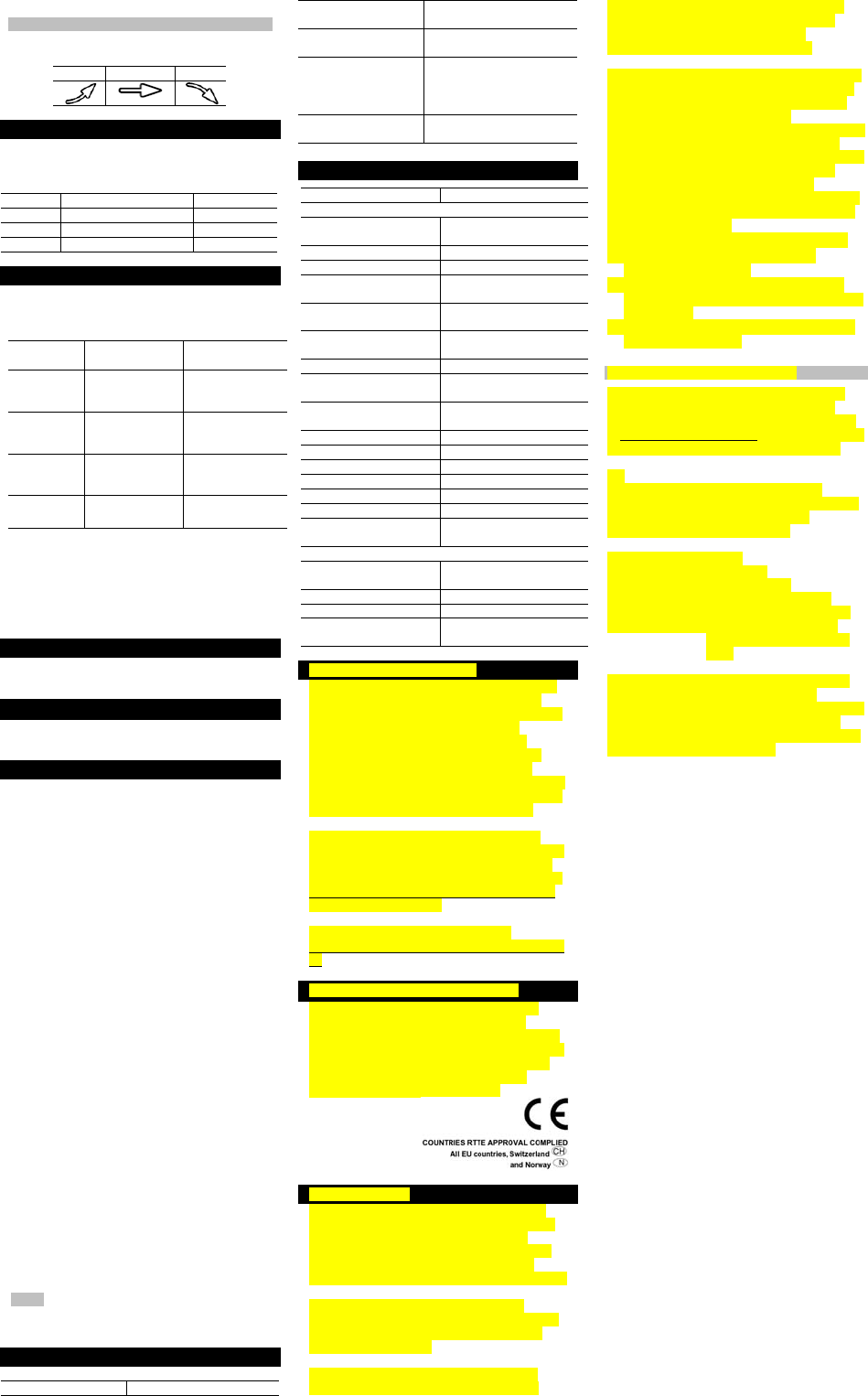
TEMPERATURE AND HUMIDITY TRENDS
The trend icons are based on recent readings.
RISE STEADY FALL
COMFORT ZONE
The comfort zone assesses the climate based on
the current temperature and humidity. It is shown
beside the humidity display.
ICON TEMPERATURE HUMIDITY
WET Any > 70%
COM 20 - 25°C (68 - 77°F) 40 - 70%
DRY Any < 40%
HEAT INDEX
The heat index combines temperature and
humidity data to describe the actual temperature
felt.
WARNING HEAT INDEX MEANING
Extreme
danger 54.5°C / 130°F
or above Strong risk of
dehydration / sun
stroke
Danger 105- 129°F/ 40.5-
3.9°C
Heat exhaustion
likely
Extreme
caution
90- 104°F /
32.2 - 40°C Possibility of heat
dehydration
Caution 80- 89°F / 26.6-
31.7°C Possibility of heat
exhaustion
To display the Heat Index:
1. Press SELECT to navigate to the
Temperature and Humidity Area.
2. Press MODE to reach the Heat Index display.
3. Press CHANNEL to select the desired
channel.
S
BACKLIGHT
Press SNOOZE / LIGHT to activate the backlight
for 8 seconds.
RESET
To return the unit to the default settings, press
RESET.
PRECAUTIONS
This product is engineered to give you years of
satisfactory service if you handle it carefully.
Here are a few precautions:
• Placement of this product on wood surfaces
with certain types of finishes, such as clear
varnish, may result in damage to the finish.
Consult the furniture manufacturer's care
instructions for direction as to the types of
objects that may safely be placed on the
wood surface. Oregon Scientific shall not be
responsible for any damage to wood surfaces
from contact with this product.
• Do not immerse the unit in water. If you spill
liquid over it, dry it immediately with a soft,
lint-free cloth.
• Do not clean the unit with abrasive or
corrosive materials.
• Do not subject the unit to excessive force,
shock, dust, temperature or humidity, which
may result in malfunction, shorter electronic
life span, damaged battery and distorted
parts.
• Do not tamper with the unit’s internal
components. Doing so will invalidate the
warranty on the unit and may cause
unnecessary damage. The unit contains no
user-serviceable parts.
• Do not dispose this product as unsorted
municipal waste. Collection of such waste
separately for special treatment is necessary.
• Due to printing limitations, the displays shown
in this manual may differ from the actual
display.
• The contents of this manual may not be
reproduced without the permission of the
manufacturer.
NOTE The technical specifications for this
product and the contents of the user manual are
subject to change without notice.
TROUBLESHOOTING
Problem Remedy
Strange barometer
readings Set the altitude / unit
Can’t adjust clock
setting Disable clock signal
reception
Can’t receive clock
signals
• Adjust batteries
• Press RESET
• Activate clock signal
reception
Can’t locate remote
sensor Check batteries
SPECIFICATIONS
TYPE DESCRIPTION
MAIN UNIT
L x W x H 120 x 86 x 188 mm
(4.7 x 3.4 x 7.4 in)
Weight 376 g (13.3 oz)
Temperature unit °C / °F
Indoor temperature
range -5°C to 50°C
(23°F to 122°F)
Outdoor temperature
range -20°C to 60°C
(-4°F to 140°F)
Temperature
Resolution 0.1°C (0.2°F)
Indoor Humidity range 25% to 95%
Temperature
Resolution 1%
Weather display Rainy, cloudy, partly
cloudy, sunny
Clock signal frequency 433 MHz
Clock display format 12 or 24 hour format
Clock display HH:MM:SS
Alarm duration 2 minutes
Snooze 8 minutes
Channels 5
Power 4 x UM-3 (AA) 1.5 V
batteries
REMOTE SENSOR (RTGR382N)
L x W x H 70 x 25 x 116 mm
(2.8 x 1.0 x 4.6 in)
Weight 108 g (3.8 oz)
Range 70 m (230 ft)
Power 2 x UM-3 (AA) 1.5 V
batteries
ABOUT OREGON SCIENTIFIC
Visit our website (www.oregonscientific.com) to
learn more about Oregon Scientific products
such as digital cameras; MP3 players; children’s
electronic learning products and games;
projection clocks; health and fitness gear;
weather stations; and digital and conference
phones. The website also includes contact
information for our Customer Care department in
case you need to reach us, as well as frequently
asked questions and customer downloads.
We hope you will find all the information you
need on our website, however if you’re in the US
and would like to contact the Oregon Scientific
Customer Care department directly, please visit:
www2.oregonscientific.com/service/default.asp
OR Call 1-800-853-8883.
For international inquiries, please visit:
www2.oregonscientific.com/about/international.a
sp
EU-DECLARATION OF CONFORMITY
Hereby, Oregon Scientific, declares that the
Weather Station Model: BAR990HG is in
compliance with the essential requirements and
other relevant provisions of Directive 1999/5/EC.
A copy of the signed and dated Declaration of
Conformity is available on request via our
Oregon Scientific Customer Service.
FCC STATEMENT
This device complies with Part 15 of the FCC
Rules. Operation is subject to the following two
conditions: (1) This device may not cause
harmful interference, and (2) This device must
accept any interference received, including
interference that may cause undesired operation.
WARNING Changes or modifications not
expressly approved by the party responsible for
compliance could void the user's authority to
operate the equipment.
NOTE This equipment has been tested and
found to comply with the limits for a Class B
digital device, pursuant to Part 15 of the FCC
Rules. These limits are designed to provide
reasonable protection against harmful
interference in a residential installation.
This equipment generates, uses and can radiate
radio frequency energy and, if not installed and
used in accordance with the instructions, may
cause harmful interference to radio
communications. However, there is no guarantee
that interference will not occur in a particular
installation. If this equipment does cause harmful
interference to radio or television reception,
which can be determined by turning the
equipment off and on, the user is encouraged to
try to correct the interference by one or more of
the following measures:
• Reorient or relocate the receiving antenna.
• Increase the separation between the
equipment and receiver.
• Connect the equipment into an outlet on a
circuit different from that to which the receiver
is connected.
• Consult the dealer or an experienced radio /
TV technician for help.
DECLARATION OF CONFORMITY
The following information is not to be used as
contact for support or sales. Please call our
customer service number (listed on our website
at www.oregonscientific.com), or on the warranty
card for this product) for all inquiries instead.
We
Name: Oregon Scientific, Inc.
Address: 19861 SW 95th Ave.,Tualatin,
Oregon 97062 USA
Telephone No.: 1-800-853-8883
declare that the product
Product No.: BAR990HG
Product Name: Weather Station
Manufacturer: IDT Technology Limited
Address: Block C, 9/F, Kaiser Estate,
Phase 1,41 Man Yue St.,
Hung Hom, Kowloon, Hong
Kong
is in conformity with Part 15 of the FCC Rules.
Operation is subject to the following two
conditions: 1) This device may not cause harmful
interference. 2) This device must accept any
interference received, including interference that
may cause undesired operation.