IDT Technology STC300-01 Ultra-precision Professional Weather System User Manual WMR300 EN R25 indd
IDT Technology Limited Ultra-precision Professional Weather System WMR300 EN R25 indd
Contents
- 1. User Manual 1
- 2. User Manual 2
User Manual 1
1
EN
INTRODUCTION
Thank you for selecting the Oregon Scientific™ Ultra-precision Professional
Weather System (WMR300 / WMR300A).
This system can provide you with weather information through several sensors
with high level of accuracy. All sensors are cabled to a transmitter box which is
battery and solar powered operated for wirelessly communicating and displaying
the data on an indoor LCD main unit.
This system remembers the data for a time range for you to monitor and analyze
the weather status. You can also export the data to PC by cable and manage and
analyze the data systematically.
The system can expand up to 8 thermometer & humidity sensors and be compatible
with other weather sensors. To purchase additional sensors, please contact your
local retailer.
Please keep this manual handy as you use your new product. It contains
practical step-by-step instructions, as well as technical specifications and warnings
you should know about.
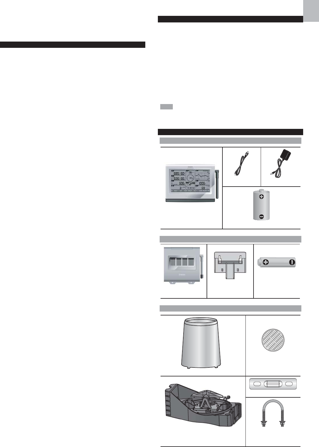
PACKAGING CONTENTS
DISPLAY UNIT
1 x Main unit
1 x USB cable 1 x Power adapter
3 x C 1.5V battery
SOLAR TRANSMITTER
1 x Solar transmitter
(STC300/300A)
1 x Mounting insert
1 x AA 1.2V
rechargeable battery
RAIN GAUGE
1 x Rain collector
1 x Plastic debris filter
1 x Rain gauge
(PCR300)
1 x Backing metal plate
1 x U-bolt
(with 2 x lock washer
& 2 x flat washer & 2 x hex nut)
Ultra-precision Professional Weather System
Model: WMR300 / WMR300A
USER MANUAL
CONTENTS
Introduction ....................................................................................................... 1
Packaging Contents ......................................................................................... 1
Display Unit ................................................................................................... 1
Solar Transmitter ........................................................................................... 1
Rain Gauge ................................................................................................... 1
Temperature & Humidity Sensor .................................................................... 2
Wind Sensor .................................................................................................. 2
Assembly Part ............................................................................................... 2
Accessories - Sensors ..................................................................................... 2
Overview ............................................................................................................ 2
Main Unit ........................................................................................................ 2
Transmitter Box .............................................................................................. 2
Rain Gauge .................................................................................................... 3
Temperature & Humidity Sensor .................................................................... 3
Wind Sensor .................................................................................................. 3
Detailed LCD Display ........................................................................................ 3
LCD Display .................................................................................................... 3
Indoor Temperature & Humidity ..................................................................... 3
Outdoor Temperature & Humidity .................................................................. 4
Dew Point / Heat Index / Wind Chill .............................................................. 4
Sunrise / Sunset ............................................................................................ 4
Wind Speed / Wind Direction ........................................................................ 4
Clock / Alarm / Weather Forecast / Moon Phase ............................................ 4
Bar Chart ....................................................................................................... 4
Barometer ...................................................................................................... 5
Rainfall ........................................................................................................... 5
Installation ......................................................................................................... 5
Set up Rain Sensor & Thermo / Hygro Sensor ................................................ 5
Set up Wind Sensor ...................................................................................... 5
Set up Transmitter Box ................................................................................ 5
Cable Connections ........................................................................................ 5
Transmitter Box-Battery Installation ............................................................... 6
Channel Setting ............................................................................................. 6
Remove Setting ............................................................................................. 6
LED Light Indicator ......................................................................................... 6
Sensors Installation ....................................................................................... 6
Main Unit-Batteries Installation ......................................................................... 7
Pairing Sensors / Remove Sensors ............................................................... 7
Clock .................................................................................................................. 7
Manually Set Clock ........................................................................................ 7
Clock Reception ............................................................................................ 8
Alarm Clock ................................................................................................... 8
Moon Phase ....................................................................................................... 8
Weather Forecast .............................................................................................. 8
Temperature and Humidity .............................................................................. 8
Dewpoint / Heat Index / Wind Chill .................................................................. 8
Sunrise / Sunset ................................................................................................ 9
Wind ................................................................................................................... 9
Direction Calibration ...................................................................................... 9
Wind Speed / Direction .................................................................................. 9
Barometric Pressure ........................................................................................ 9
Rainfall ............................................................................................................... 9
Accumulated Rainfall ..................................................................................... 9
Bar Chart ........................................................................................................... 9
Memory ............................................................................................................. 10
Max / Min of Today / Monthly Records ......................................................... 10
Hourly Records ............................................................................................. 10
Data Log ....................................................................................................... 10
Alarm ................................................................................................................. 10
Backlight ........................................................................................................... 11
Reset .................................................................................................................. 11
Maintainance ..................................................................................................... 11
To Maintain the Thermo / Hygro Sensor ......................................................... 11
Trouble Shooting .............................................................................................. 11
Precautions ..................................................................................................... 11
Specifications ................................................................................................... 12
About Oregon Scientific .................................................................................. 13
EU-declaration of Conformity ......................................................................... 13
FCC Statement ................................................................................................. 13
Declaration of Conformity ............................................................................ 13
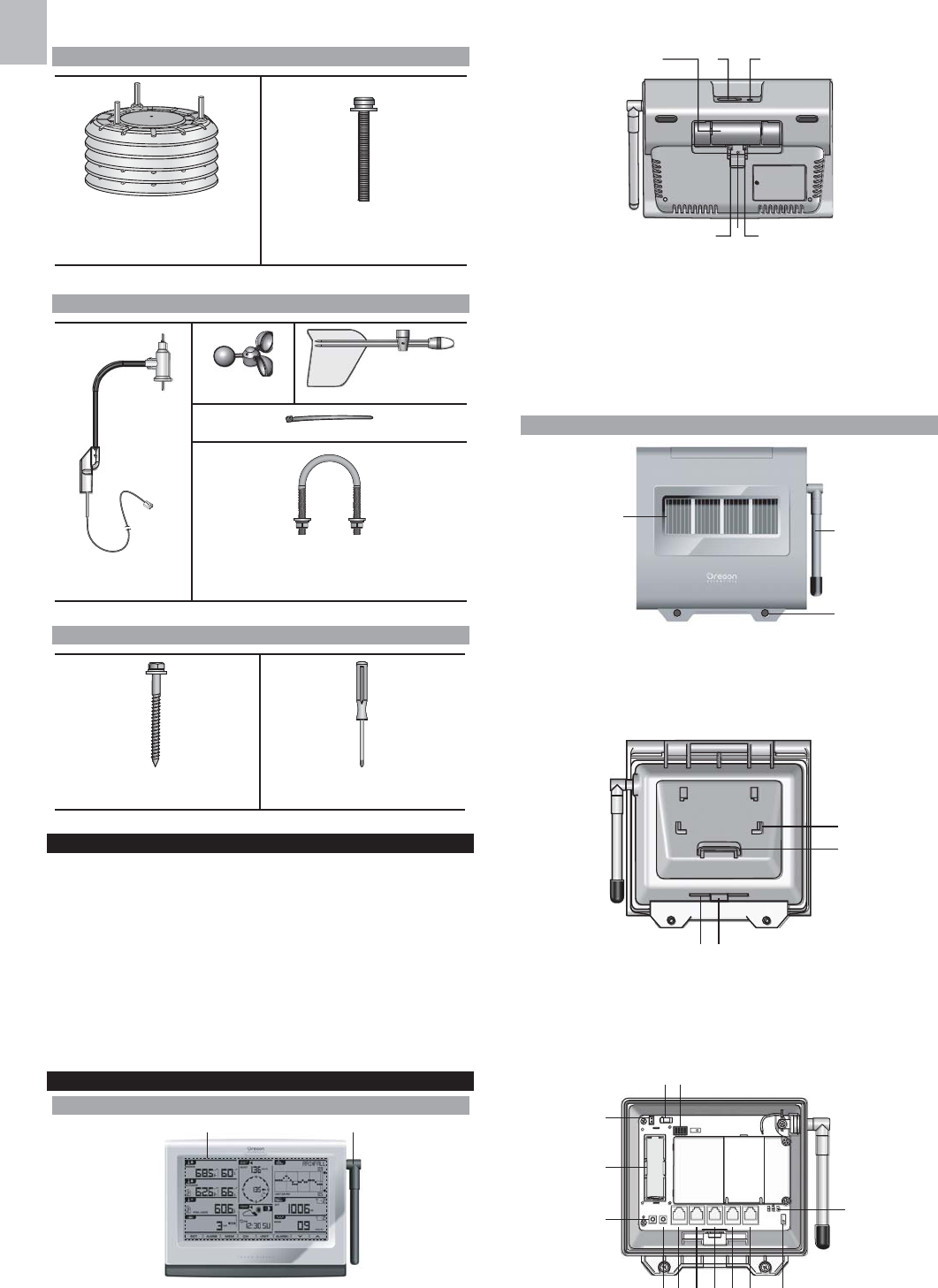
2
EN
TEMPERATURE & HUMIDITY SENSOR
1 x Thermo/hygro casing
with sensor installed
(THGN300)
3 x Screws
(Type B, with 3 x lock washer
& 3 x flat washer)
WIND SENSOR
1 x Wind sensor unit
(WGR300)
1 x Wind cups 1 x Wind vane
4 x Nylon cable tie
1 x U-bolt
(with 2 x lock washer & 2 x flat washer
& 2 x hex nut)
ASSEMBLY PARTS
2 x Screws (Type A, with 2 x
lock washer & 2 x flat washer) 1 x Screw driver
ACCESSORIES - SENSORS
The system can expand up to 8 thermometer & humidity sensors and be compatible
with other weather sensors. Optional wireless remote sensors (coming soon) such
as those listed below can be purchased separately. For more information, please
contact your local retailer.*
• Wireless repeater (Expand the transmission range)
• UV sensor (UV index & UV dose)
• Solar radiation sensor (Solar radiation, THSW & Evapotranspiration (ET))
• Aspirated fan (Increase accuracy of temp/humidity sensor)
• Soil/Leaf sensor (Soil moisture/temperature & Leaf wetness)
* Features and accessories will not be available in all countries.
OVERVIEW
MAIN UNIT
Figure 1 - Front View
1. LCD display
2. Antenna
Figure 2 - Back View
1. Battery compartment
2. USB socket
3. Power adapter socket
4. Backlight (continuous) slide switch ON/OFF
5. RESET: Reset unit to default settings
6. EU/UK slide switch (WMR300 only)
TRANSMITTER BOX
Figure 3 - Front View
1. Solar panel
2. Antenna
3. Screw holes
Figure 4 - Back View
1. Cable slot
2. Rubber stopper
3. Mounting bracket
4. Mounting ring
Figure 5 – Inside View
3
EN
1. Power adapter socket (optional)
2. Channel setting slide switches (SW1)
3. Color-coded connector for connecting solar panel
4. Rechargeable battery compartment
5. RESET button
6. KEY button: for wind direction calibration
7. UV sensor socket (not available now)
8. SOLAR sensor socket (not available now)
9. RAIN sensor socket
10. TH (temperature & humidity sensor) socket
11. WIND sensor socket
12. Pairing slide switch (SW4)
13. LED lights (blue/green/red)
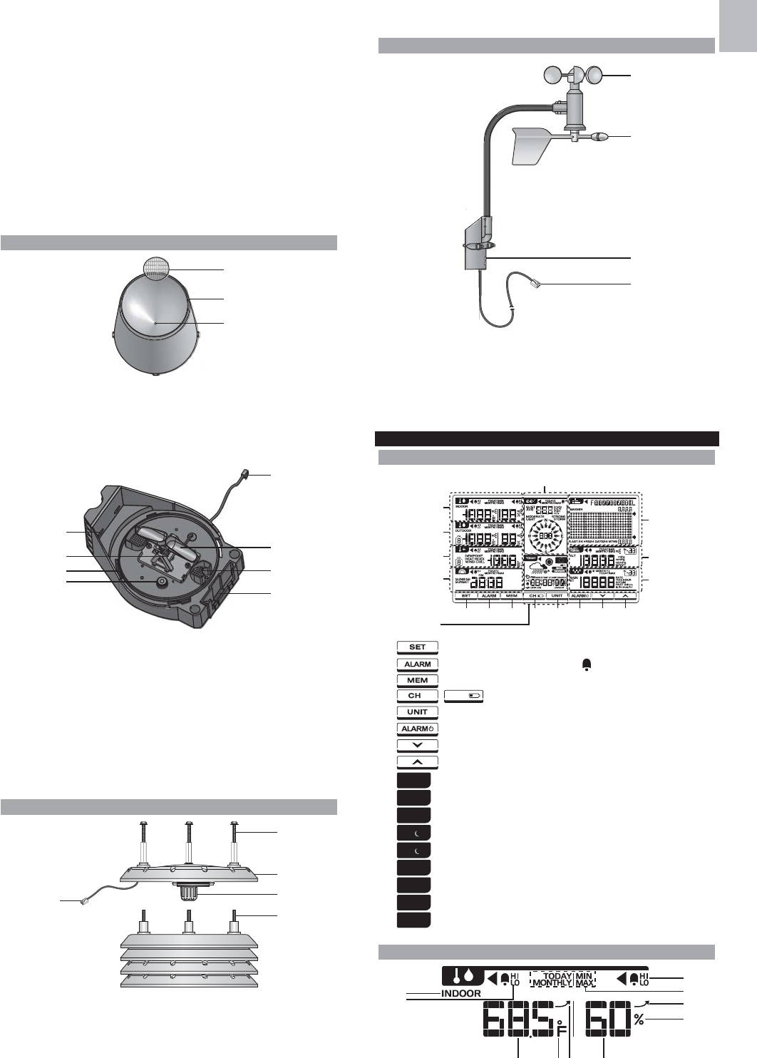
RAIN GAUGE
Figure 6 – Top View
1. Plastic debris filter
2. Rain collector
3. Collector hole
Figure 7 – Bottom View
1. Screw holes
2. Rain sensor
3. Rain collector installation hole
4. Balance indicator
5. Sensor cable
6. Tipping bucket
7. Drain holes
8. Hole for mounting insert
TEMPERATURE & HUMIDITY SENSOR
Figure 8
1. Screws (Type B)
2. Sensor casing
3. Temperature and humidity sensor
4. Screws (pre-installed)
5. Sensor cable
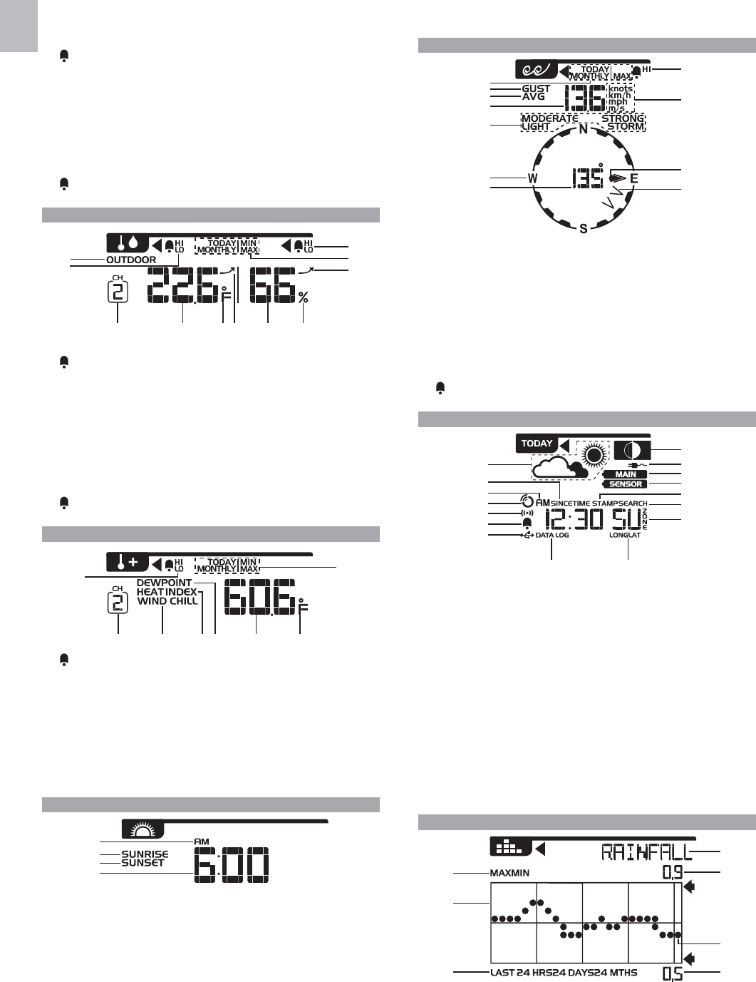
WIND SENSOR
Figure 9
1. Wind cups (anemometer)
2. Wind vane
3. Wind sensor holder
4. Sensor cable
DETAILED LCD DISPLAY
LCD DISPLAY
1. : Enter setting modes
2. : Set and view status of clock and HI/LO alarms
3. : View current reading and memory.
4. / : Toggle between 8 different channels / low battery indicator
5. : Change display/measurement units
6. : Turn alarm on or off
7. : Press to decrease value
8. : Press to increase value
9. Clock / alarm / weather forecast / moon phase
10. Sunrise/sunset area
11. Dew point / heat index / wind chill area
12. Outdoor temperature and humidity area
13. Indoor temperature and humidity area
14. Wind speed / direction area
15. Bar chart area
16. Barometer area
17. Rainfall area
INDOOR TEMPERATURE & HUMIDITY
4
EN
1. Indoor temperature/humidity indicator
2. HI/LO alarm: Alarms for high or low indoor temperature
3. Indoor temperature reading
4. ˚C / ˚F: Temperature unit
5. Indoor temperature trend
6. Indoor humidity reading
7. %:Humidity unit
8. Indoor humidity trend
9. TODAY/MONTHLY/MIN/MAX: Display the maximum/minimum of today’s/
monthly indoor temperature / humidity reading
10. HI/LO alarm: Alarms for high or low indoor humidity
OUTDOOR TEMPERATURE & HUMIDITY
1. Outdoor temperature/humidity indicator
2. HI/LO alarm: Alarms for high or low outdoor temperature
3. Selected channel
4. Outdoor temperature reading
5. ˚C / ˚F: Temperature unit
6. Outdoor temperature trend
7. Outdoor humidity reading
8. %: Humidity unit
9. Outdoor humidity trend
10. TODAY/MONTHLY/MIN/MAX: Display the maximum/minimum of today’s/
monthly outdoor temperature / humidity reading
11. HI/LO alarm: Alarms for high or low outdoor humidity
DEW POINT / HEAT INDEX / WIND CHILL
1. HI/LO alarm: Alarms for high or low temperature
2. Selected channel
3. Wind chill indicator (From CH1 reading only)
4. Heat index indicator
5. Dew point indicator
6. Dew point / heat index / wind chill temperature
7. ˚C / ˚F: temperature unit
8. TODAY/MONTHLY/MIN/MAX: Display the maximum/minimum of today’s/
monthly dew point/heat index/wind chill reading
SUNRISE / SUNSET
1. AM/PM
2. Sunrise indicator
3. Sunset indicator
4. Time display
WIND SPEED / WIND DIRECTION
1.
TODAY/MONTHLY/MAX: Display the maximum today’s / monthly gust wind reading
2. Gust wind indicator
3. Average wind indicator
4. Wind speed reading
5. MODERATE/LIGHT/STRONG/STORM: Wind speed level indicators
6. W(West) / S(South) / E(East) / N(North)
7. Wind direction reading/calibrated angle reading
8. Wind direction indicator(s) during last 1 hour
9. Gust / average wind direction indicator
10. Knots / km/h / mph / m/s: Wind speed unit
11. HI alarm: Alarms for high wind speed
CLOCK / ALARM / WEATHER FORECAST/ MOON PHASE
1. Weather forecast icon area
2. SINCE: Start date of the accumulated rainfall
3. AM/PM
4. RF clock signal reception indicator
5. Alarm display mode
6. Daily alarm indicator
7. USB port is successfully connected
8. DATA LOG: Data log information displays
9. LONG/LAT: Longitude/Latitude
10. Time zone offset
11. SEARCH: Searching for solar transmitter
12. TIME STAMP: Particular time of the selected memory
13. Solar transmitter is low battery
14. Main unit is low battery
15. Power adapter is connected
16. Moon phase area
BAR CHART
1. MAX/MIN: Maximum/minimum reading indicator of selected area
2. Bar chart area
3. LAST 24HRS/24DAYS/24 MTHS: Time range
4. Minimum reading for reference
5. Current graph reading of the corresponding area
6. Maximum reading for reference
7. IN TEMP/IN HUM/OUT TEMP/OUT HUM/DEWPOINT/HEAT INDEX/
WIND CHILL/WIND/BARO/RAINFALL: Chart mode indicators
5
EN
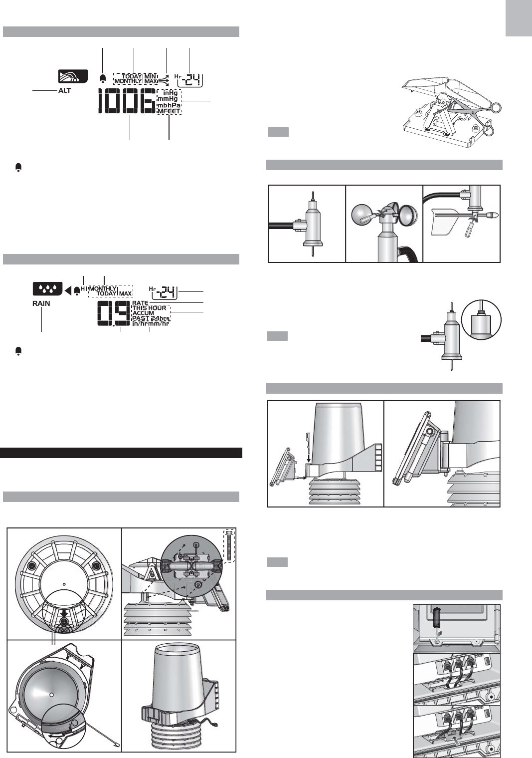
BAROMETER
1. Altitude area indicator
2. : Alarm for changes of barometric pressure
3. TODAY/MONTHLY/MIN/MAX: Display the maximum/minimum of today’s/
monthly barometric pressure reading
4. Barometer trend
5. Hourly records indicator (From -24 to 0)
6. inHg / mmHg / mb / hPa: Barometer unit
7. M / FEET: Altitude unit
8. Barometer reading
RAINFALL
1. HI alarm: Alarms for high rain rate and past 24-hour rainfall.
2. TODAY/MONTHLY/MAX: Display the maximum of today’s/monthly rainfall/rain
rate reading
3. Hourly records indicator (From -24 to 0)
4. RATE: Rainfall rate
5. THIS HOUR/ACCUM/PAST 24hrs: Selected time range
6. In/mm: Rainfall unit; In/hr / mm/hr: Rain rate unit
7. Rain reading display
8. Rain area indicator
INSTALLATION
Please prepare some tools before starting your installation. You may need some
types of screw drivers, wrenches or an electric drill.
SET UP RAIN SENSOR & THERMO / HYGRO SENSOR
The rain gauge collects rain and takes rainfall readings. The transmitter box can
wirelessly transmit data to the main unit.
1. Make sure the engraved arrow on the thermo/hygro sensor casing towards the
installation direction of the transmitter box.
2. Align three screw holes on the rain gauge with the three double end studs on
the thermo/hygro sensor casing.
3. Tightly twist the type B screws into the double end studs to make sure the
connection is firmly.
4. Put the rain collector on the rain gauge
aligning the tipping with the holes, and
then twist clockwise to secure it tightly.
5.
Put the plastic debris filter in the rain collector
.
Cut away the cable tie on the tipping
bucket before using.
SET UP WIND SENSOR
The wind sensor takes wind speed and direction readings.
1. Loosen the screws in the wind cups and wind vane.
2. Insert the top of the wind sensor unit into the wind cups securely with some
pressure and then twist the screw tightly.
3. Insert the bottom of the wind sensor unit into the
wind vane securely with some pressure and then
twist the screw tightly.
There is a rubber washer around the top of
the wind sensor for preventing from hard touching
during installation. You can move up the rubber
washer a little bit before inserting the wind cup.
SET UP TRANSMITTER BOX
1. Approach the mounting ring of the transmitter box to the rain gauge, and align
mounting ring with the bottom of the hole of the rain gauge.
2. Insert the mounting insert into the mounting ring of the transmitter box through
the hole of the rain gauge with some pressure. A click sound can be heard.
The transmitter box contains sophisticated electronic parts, so you must
treat it with care.
CABLE CONNECTIONS
It is better you connect the cables of each sensors
to the transmitter box before positioning the pole.
1. Unscrew to open the transmitter box.
2. Take off the rubber stopper from the cable slot.
3. Insert all the sensor cables through the cable slot.
4. Plug each sensor cable into corresponding
socket that has name below the socket for
recognition. A click sound can be heard.
5. Return the rubber stopper to the cable slot.
6
EN
TRANSMITTER BOX-BATTERY INSTALLATION
The solar panel on transmitter box is an energy saving feature, which is an
environmentally friendly way to provide power to the sensors and prolongs battery
life. It can entirely provide power to the supplied rechargeable battery. Sensors
can operate entirely on the rechargeable battery power. Locate the transmitter box
under direct sunlight for power supplying by the solar panel.
The rechargeable battery from factory is not with full
battery for long time use and it probably becomes
low battery during the shipping. We recommend
you to charge it for several hours by the connected
solar panel.
You can also purchase a power adapter separately
for directly providing power to the transmitter box.
The output voltage of the power adapter is 3V.
Route the adapter cable through the cable slot.
Please check the solar panel connection. If it
is not firmly plugged, please re-connect the
solar panel:
Plug the end of color-corded connector into corresponding socket in the transmitter
box as shown below and place the wires neatly inside the box.
To install the rechargeable battery:
Insert the battery into the battery compartment, matching the polarity +/-.
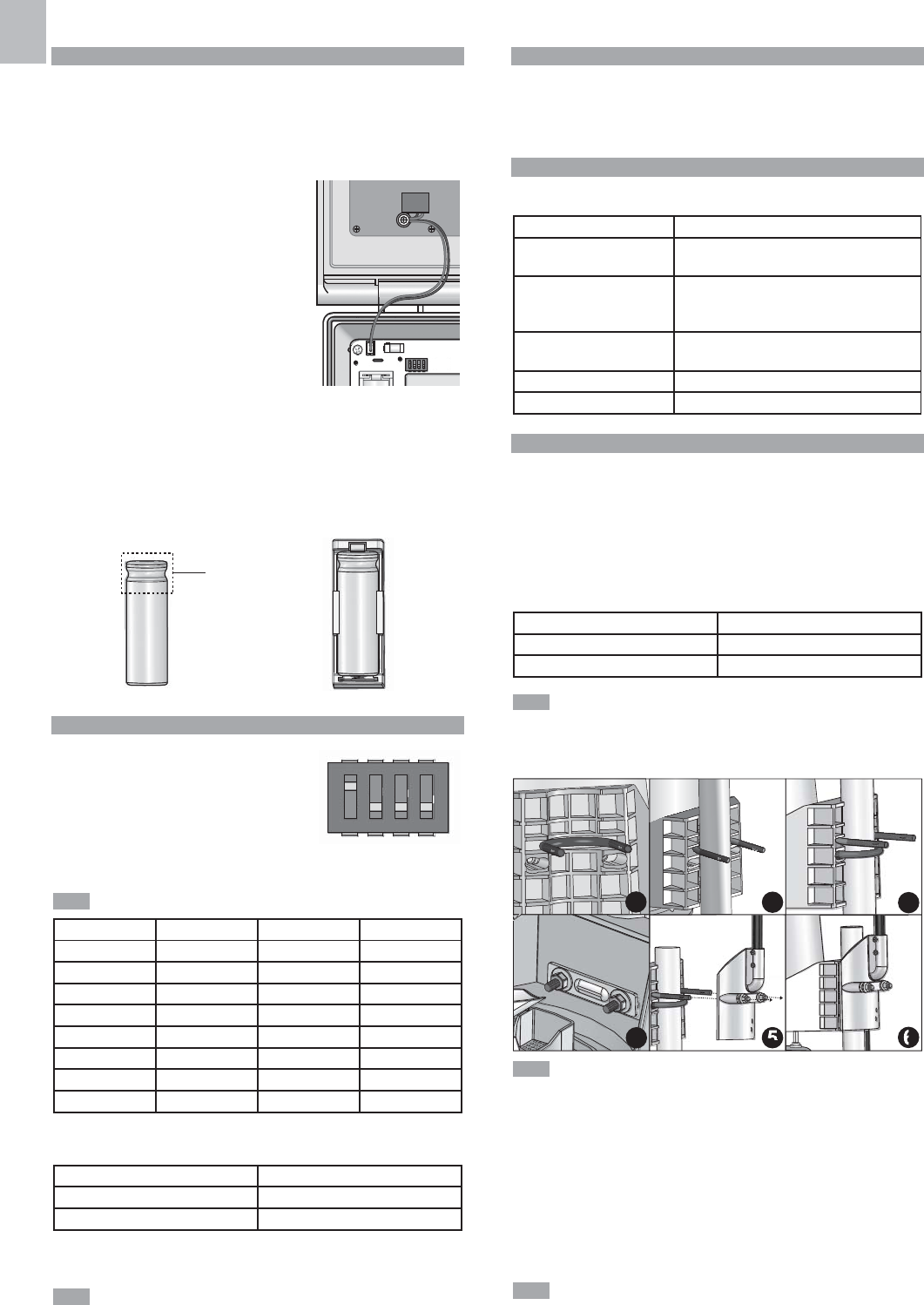
CHANNEL SETTING
Your weather station system can expand with up to 8
sets of thermometer & humidity sensors, and one of
each of wind and rain sensors, which share one main
unit to display the weather readings. You can number
each transmitter box with an independent channel ID
(1-8) by sliding the switches.
Please follow the below chart to adjust the sliding switches of SW1:
The below 0 in the chart represents off and 1 represents on.
CH PIN 2 PIN 3 PIN 4
Channel 1 000
Channel 2 001
Channel 3 010
Channel 4 011
Channel 5 100
Channel 6 101
Channel 7 110
Channel 8 111
For obviously indicate the status of your channel, you can turn on the LED light in
the corresponding transmitter box by sliding the PIN 1 switch to 1.
Function PIN 1
Disable LED 0
Enable LED 1
After setting, please turn off the LED light by sliding the PIN 1 switch to 0 to save
power, and then close the box by tightening the screws.
The flashing LED indicates a normal transmission (See LED Light Indicator).
REMOVE SETTING
For removing the previous setting from the transmitter box, you can press RESET
and KEY at a time, then only release RESET, red light flashes 5 times. Then
release KEY. The channel setting and calibrated wind direction are all removed
from the transmitter box.
LED LIGHT INDICATOR
There are three colors of LED lights in transmitter box, green, red and blue.
Different color combinations indicate different status.
Light Color Operations
Blue->green->red Flash once when you (Press and )release
RESET
Red flashes every second Flash 5 times then remove setting of all the
sensors from transmitter box (See Remove
setting section)
Red Wind direction calibration
(See Direction Calibration).
Blue flashes A normal transmission (WMR300A)
Green flashes A normal transmission (WMR300)
SENSORS INSTALLATION
You have three options to install the sensors.
The transmitter box is capable of transmitting data wirelessly an approximate
operating range of 300m (1000 feet). Ideal placements for the sensor would be
in any location on the roof of a building that is in an open area away from trees
or other obstructions preventing from the wind flow for an accurate reading.
Additionally, locate the transmitter box at the direct sunlight for power supplying
by the solar panel.
Solar panel facing: If you reside in the:
North Southern Hemisphere
South Northern Hemisphere
Make sure the temperature and humidity sensor should be located at least
1.5 meters above the ground surface to avoid the ground temperature affecting
accuracy of the temperature and humidity sensor.
Option 1: All sensors are installed on a pole.
Please take off the rain collector before installation and choose a pole with
the diameter that is about 32-45mm.
1. Locate one U-bolt without flat washers, lock washers and hex nuts into the gap
of the rain gauge (Figure 1).
2. Let the pole fully approach to the inner of the U-bolt (Figure 2).
3. Locate the other U-bolt without flat washers, lock washers and hex nuts into
the screw holes of the rain gauge (Figure 3).
4. Put the backing metal plate through the U-bolt and securely tighten two pairs of
the flat washers, lock washers and hex nuts over the plate (Figure 4) by wrench.
5. Insert the two ends of the first U-bolt into the screw holes of the wind sensor (Figure 5).
6. Tighten the other two pairs of flat washers, lock washers and hex nuts on the
U-bolt of the wind sensor by wrench (Figure 6).
Make sure the water bubble in the balance indicator on the rain gauge
stay within the circle. Check the balance status regularly for an accurate rainfall
rate reading.
7
EN
7. Follow the instructions in sections of Cable Connections, Transmitter Box-
Battery Installation and Channel Setting.
8. Securely locate the pole in your desired outdoor area.
9. Route the excessive cables neatly by using the provided cable ties.
6 meters wind sensor cable is provided for you to locate the wind sensor
separately from the pole like in Option 2 and Option 3. Route the excessive
cables if necessary.
Put the plastic debris filter into the rain collector. Please check the filter
regularly and ensure it is not fully covered by the leaves or other objects.
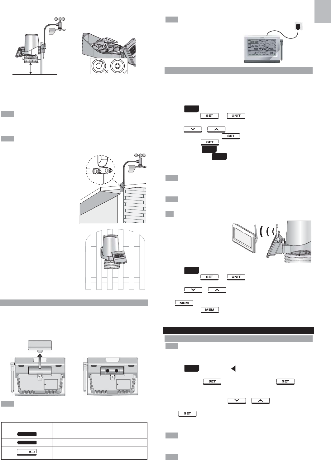
Option 2: Wind sensor is installed
separately; other sensors with transmitter
box are installed on a pole.
1. Follow the steps 3-4 in Option 1 to
install the temperature/hygro sensor
and rain sensor on a pole.
2. Insert the Type A screws into the wind
sensor. Securely screw them into your
desired location using wrench.
3. Follow the steps 7-9 in Option 1 to
complete the installation.
Option 3: Excepting wind sensor is
installed on a pole; other sensors with
transmitter box are installed separately.
1. Follow the steps 5-6 in Option 1 to install
the wind sensor on a pole.
2. Insert the Type A screws into the rain
gauge. Securely screw them into your
desired location using wrench.
3. Follow the steps 7-9 in Option 1 t o
complete the installation.
MAIN UNIT-BATTERIES INSTALLATION
To insert batteries:
1. Remove the battery compartment cover.
2. Insert the supplied batteries in the compartment, matching the polarities (+ / -).
3. Press RESET in the compartment.
4. Close the battery compartment cover.
Do not use rechargeable batteries. It is recommended that you use alkaline
batteries with this product for longer performance.
Low battery indicators:
Icon Meaning
Main unit batteries low
Transmitter box(es) batteries low
Transmitter box(es) / main unit batteries low
For continuous use, install the power adapter. The batteries are for back-up use only.
Plug the power adapter into an electrical outlet not controlled by a wall switch.
The power adapter is intended
to be correctly oriented in a vertical or
floor mount position. The prongs are not
designed to hold the plug in place if it is
plugged into a ceiling, under-the-table or
cabinet outlet.
PAIRING SENSORS / REMOVE SENSORS
For the first time of pairing, please place the main unit close to the solar transmitter
box for a quick and better signal linkage.
To pair a sensor:
1. The SW4 pairing switch in transmitter box is set to 1 (ON).
2. Press area.
3. Press and hold and at a time until you enter sensor setup
mode. (All sensor readings disappear on the screen, - - displays on the screen.)
4.
Press or to select the channel you want to add the sensor.
The channel in dash mode ( displays) is available for pairing a sensor.
5. Press and hold for 2 seconds. There is a beep. Press anywhere on
the panel not in area.
6. SEARCH indicator in area flashes to do pairing.
7. When SEARCH disappears and the selected channel of sensor displays the
weather reading on the screen, the pairing is complete and successful.
The main unit searches the sensor for about 10 minutes. Please complete
the pairing within an hour after you switch on the pairing switch in the transmitter box.
Otherwise, you need to turn off the pairing switch, and then switch it on again.
Make sure you calibrate the direction of wind vane on the wind sensor after
adding sensors, see Direction Calibration for details.
The transmission range may vary depending on many factors. You may
need to experiment with various
locations to get the best results.
Make the antenna of the transmitter
box and the one on the main unit
be paralleled to get a better pairing
performance.
To remove a sensor:
1. Press area.
2. Press and hold and at a time until you enter sensor setup
mode. (The weather reading disappears on the screen, - - displays on the screen).
3. Press or to select the channel of the sensor you want to
remove. You can only remove the sensor that the reading is not in dash mode
( displays).
4. Press and hold for at least 2 seconds. There is a beep and then the
screen shows - -, the sensor is successfully removed from the main unit.
CLOCK
MANUALLY SET CLOCK
To set the clock/calendar manually, disable the clock signal reception first
(see To Enable / Disable signal reception).
To manually set the clock / calendar:
1. Press area to activate. displays next to the area and the tool bar
displays at the below of the screen.
2. Press and hold on the tool bar, then toggle between
time zone offset, day time saving options, 12/24 hr format, hour, minute, year,
day/month format, month, day, weekday, language, latitude and longitude .
3. Once in desired setting, press or to change the settings.
4. Press:
• to confirm and continue to next setting
OR
• Touch panel area (except tool bar) to confirm and exit.
For WMR 300, the range of time zone offset is between -12 and +12. You
should manually input the time zone of your location, please check your local
weather observatory for detail. For example, Hong Kong should be set to +8.
The language options are English (E), Russian (R), Spanish (S), Italian (I),
German (D) and French (F).