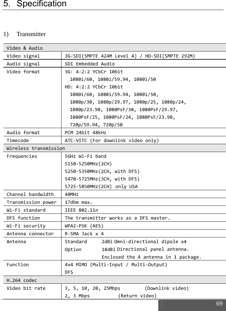
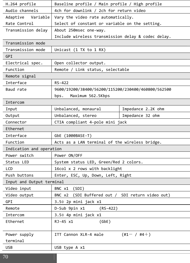
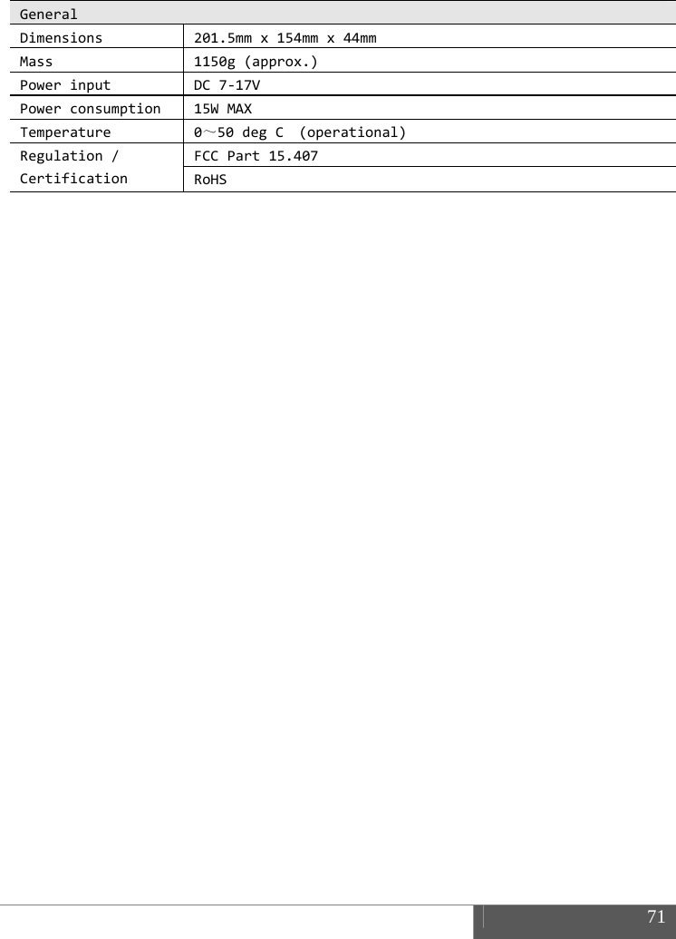
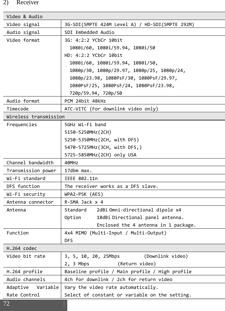
IDX CW-F25-140401 Wireless Video Transmission System User Manual CW F25 Manual US
IDX Company, Ltd. Wireless Video Transmission System CW F25 Manual US
UserManual.wiki
>
IDX
>
CW F25 140401 User Manual
User manual
Navigation menu
Upload a User Manual
Namespaces
Wiki Guide
HTML
PDF
Info
Views
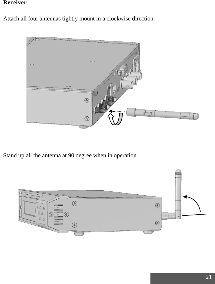
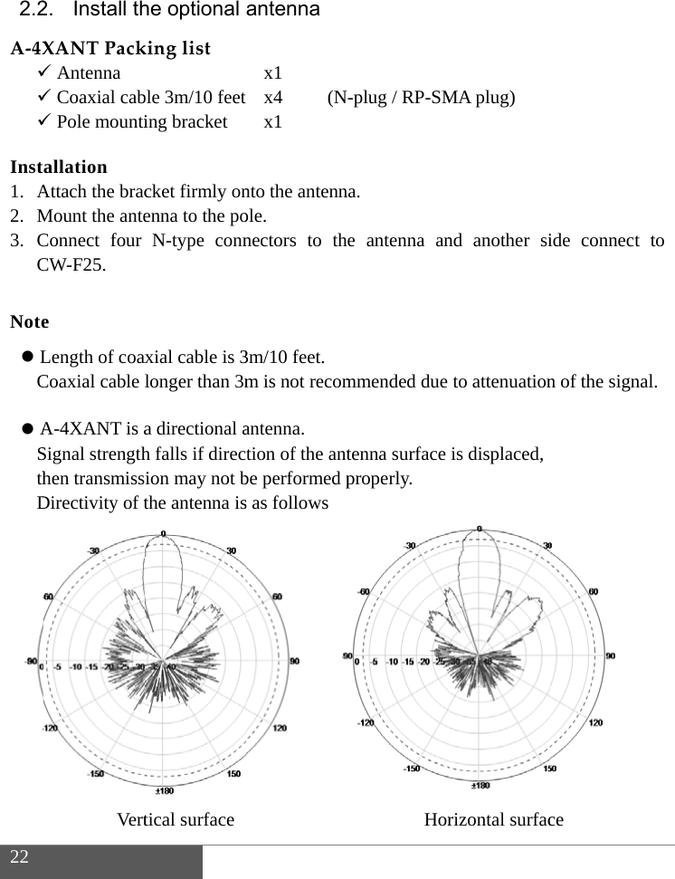
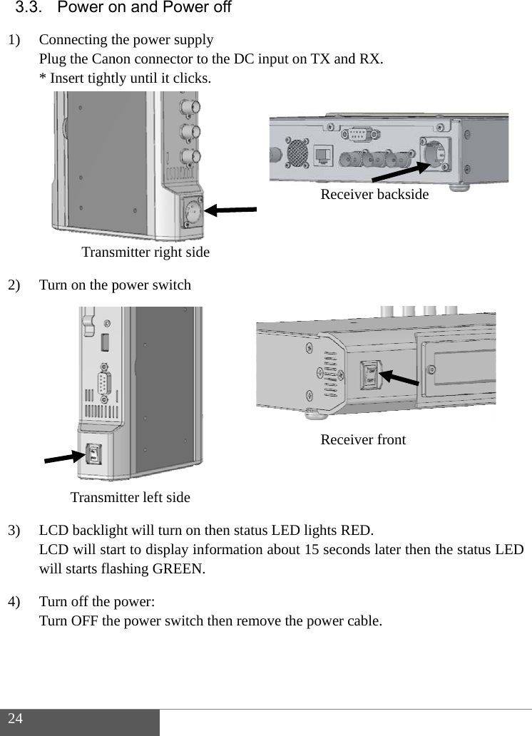
User Manual
Discussion / Help
Navigation