IDX CW-F25-140401 Wireless Video Transmission System User Manual CW F25 Manual US
IDX Company, Ltd. Wireless Video Transmission System CW F25 Manual US
IDX >
User manual

C
Inst
r
f
o
ID
X
C
W-
r
uctio
n
o
r Unite
d
X
Com
p
F2
5
n
Ma
n
d
States
p
any,
L
5
n
ual
L
td.

IDX
uni
q
Plea
T
o
e
I
u
e
I
thanks you
f
q
ue features.
se read this i
n
T
he material
o
f IDX Com
p
e
quipment de
s
I
DX Compa
n
u
se herein f
o
e
quipment de
I
DX Compan
y
f
or choosing
t
n
struction ma
n
contained in
t
p
any, Ltd. an
d
s
cribed in thi
s
n
y, Ltd. prohi
b
o
r any applic
a
scribed in th
i
y
, Ltd.
t
he CW-F25
n
ual to safely
o
t
his manual c
o
d
is intended
s
s
manual.
b
its the dupli
c
a
tion other t
h
i
s manual wi
t
and is sure t
h
o
perate and t
o
o
nsists of inf
o
s
olely for the
c
ation of any
p
h
at the oper
a
t
hout the exp
r
h
at you will
b
o
maximize p
e
o
rmation that
use by the p
u
p
ortion of thi
s
a
tion or mai
n
r
essed writte
n
b
enefit from
i
e
rformance.
is the proper
t
u
rchasers of t
h
s
manual or t
h
n
tenance of t
h
n
permission
o
i
ts
t
y
h
e
h
e
h
e
o
f

2
F
E
F
CC no
FCC condi
t
This device
c
following two
1. This devic
e
2. This devi
c
may cause u
3. This equi
p
instructions
a
provide a se
p
E
U Con
This product
marked with
harmonized
Directive 1
9
2006/95/EC.
Responsible
IDX Techn
Unit9, Lan
g
Berkshire
S
Tel: +44 1
7
Manufacture
:
IDX Comp
6-28-11 S
h
214-0021
J
tice
t
ions
c
omplies with
p
conditions:
e
may not ca
u
c
e must acce
p
ndesired ope
r
p
ment must
b
a
nd the ante
p
aration dista
n
formity
and the sup
p
"CE" and c
o
European s
t
9
99/5/EC a
n
for CE-marki
n
ology Europe
,
g
ley Park, W
a
S
L3 6AD Eng
7
53 547692
:
any, Ltd.
h
ukugawara,
T
J
apan
p
art 15 of the
u
se harmful in
t
p
t any interfe
r
r
ation.
b
e installed a
n
nna(s) used
n
ce of at least
Statem
e
p
lied access
o
o
mply therefo
t
andards list
e
n
d the Lo
w
n
g:
,
Ltd.
a
terside Drive,
land
T
ama-ku, Ka
w
FCC Rules.
O
t
erference.
r
ence receive
d
n
d operated i
for this tran
s
20 cm from
a
e
nt
o
ries (if applic
a
re with the
a
e
d under th
e
w
Voltage
Langley,
w
asaki-shi, Ka
n
O
peration is s
u
d
, including i
n
n accordanc
e
s
mitter must
a
ll persons.
a
ble) are
a
pplicable
e
R&TTE
Directive
n
agawa-ken
u
bject to the
n
terference th
e
with provid
e
be installed
t
at
e
d
t
o

3
Contents
I. Introduction ........................................................................................................... 4
1. Product overview ................................................................................ 4
2. Safety Notes ....................................................................................... 6
3. Notes of the radio waves .................................................................... 9
4. Packing list ....................................................................................... 11
5. Names of parts .................................................................................. 12
6. Optional accessories ......................................................................... 16
II. Preparation .......................................................................................................... 17
1. Installation of optional plates ........................................................... 17
2. Installation of antenna ...................................................................... 20
3. Preparing for power supply .............................................................. 23
4. Menu setting ..................................................................................... 25
III. Operation of CW-F25 ...................................................................................... 30
1. Basics ............................................................................................... 30
2. Return video ..................................................................................... 32
3. IP camera setup - wireless LAN bridge - .......................................... 34
4. Intercom operation ........................................................................... 36
5. GPI connection - as tally .................................................................. 38
6. RS-422 remote .................................................................................. 41
IV. Useful information .......................................................................................... 43
1. Troubleshooting ................................................................................ 43
2. Revert to default settings .................................................................. 49
3. Firmware update ............................................................................... 49
V. References ........................................................................................................... 51
1. List of setup menus - Rule ................................................................ 51
2. Setup menus - Transmitter ................................................................ 52
3. Setup menus - Receiver .................................................................... 60
4. Status LED ....................................................................................... 68
5. Specification ..................................................................................... 69
6. Connector and pin assignment .......................................................... 75
7. Index ................................................................................................. 76
VI. Warranty & Service ......................................................................................... 81
1. Product warranty .............................................................................. 81
2. About exemptions............................................................................. 81
3. Support & Service contact ................................................................ 82

4
I. Introduction
1. Product overview
CW-F25 is a wireless video transmission system which enable to transmit the
downlink and uplink1 video, audio and various data. Based on IEEE 802.11n
Wireless LAN technology with newly developed 4x4 MIMO and beam-forming
technology, CW-F25 enable to transmit H.264 high profile signal up to 25Mbps.
High-quality video
CW-F25 supports HD-SDI&3G-SDI and full HD video - up to 1920x1080 resolution.
A system utilized H.264 high profile compression and supports up to 25Mbps.
Adaptive variable-bit rate control
CW-F25 has an adaptive variable-bit rate control function to prevent sudden
disconnection of video and audio link due to the distance between the transmitter
and receiver and/or the deterioration of radio waves caused by the obstacles, weather
condition and so on. To minimize an unexpected shout down of the link, CW-F25
has a function to reduce the transmission video bit rate automatically. Operator can
be selected a sufficient bit rate from auto or manual by menu setting.
Optional 18dBi High-Gain 4x4 MIMO antenna array (A-4XANT)
When set the antenna array on both transmitter and the receiver, a transmission
distance can be extended up to 2Km/1.2miles LOS.
Bidirectional signal and data transmission
CW-F25 is not a ordinal downlink video transmission system but supports variety of
bidirectional signal and data such as return video, intercom, tally and RS-422
remote.
1 In this manual, the video that transmitted from a transmitter to a receiver referred as
"downlink video" and the video that transmitted from receiver to transmitter referred as "return
video".

5
Wireless LAN bridge
CW-F25 has Ethernet I/O equipped. This performs as a wireless LAN bridge
therefore it is possible to connect the IP camera, remote controller, etc.. Also this
Ethernet can simultaneously operate together with SDI video.
DFS - Dynamic Frequency Selection
CW-F25 has a DFS function built-in which detect the weather radar and avoid a
confliction with such an official radio waves. With DFS functionality, CW-F25 can
be freely used in indoor and/or outdoor without violating local law.
6
2.
Prio
r
advi
c
read
i
lead
E
*
*
2
*
3
E
!
Safety
N
r
to using t
h
c
e outlined i
n
i
ng, please k
e
to injury, fire
E
xplanatio
n
1 A serious in
j
temperature
hospitalizati
o
2
An Injury m
e
medical tre
a
treatment.
3
Physical los
s
livestock, p
e
E
xplanatio
n
Warni
n
Cautio
n
Prohibit
e
Instructi
o
N
otes
h
is product,
p
n
this manual
e
ep it in a co
n
, electric sho
c
n
of displa
y
This dis
p
injury
*1
.
This di
s
physical
-
j
ury means the
), electric sh
o
o
n for treatmen
t
e
ans a burn (hi
g
a
tment but ex
c
s
or damage m
e
e
ts, etc..
n
of signs
This dis
p
This dis
p
n
g
n
s
e
d
o
n
p
lease study
a
in order to u
s
n
venient place
c
k and produc
y
s
p
lay shows "
m
s
play shows
-
loss-or-dama
g
loss of sight a
n
o
ck, fracture,
p
t
.
g
h temperature
a
c
ludes hospita
l
e
ans damage in
p
lay means pr
o
p
lay shows in
s
a
nd follow t
h
s
e this produ
c
for future re
f
t failure.
m
ishandling
m
"mishandlin
g
g
e
*3
is possib
l
n
d an injury, a
b
p
oisoning, etc.
a
nd low temper
a
l
ization and r
e
connection wit
h
o
hibited acti
o
s
tructions (m
h
e instructio
n
c
t safely and
c
f
erence. Inco
r
m
ay cause de
a
g
may caus
e
l
e."
b
urn (high temp
requiring me
d
a
ture), an elect
r
e
gular hospital
h
a property, ho
o
n (must not
b
ust be carrie
d
n
carefully a
n
c
orrectly. Aft
e
r
rect usage m
a
a
th or seriou
s
e
injury
*2
, o
r
erature and lo
w
d
ical treatment
r
ic shock, etc. i
n
attendance fo
usehold effects
b
e carried out)
d
out).
n
d
e
r
a
y
s
r
w
,
n
r
,
.
Wa
r
If you n
coming
the po
w
Continue
d
Be care
f
do not
p
It may ca
u
Do not
p
It may ca
u
If liqui
d
immedi
a
recepta
c
Continue
d
Do not
combu
s
turn the
electric
a
Continue
d
Do not
d
It may ca
u
Do not
d
a heavy
If the po
w
Do not
u
It may ca
u
Insert t
h
Failure to
Before
u
within t
h
Input volt
a
Before
u
the con
n
Reverse
p
!
!
!
!
!
!
r
ning
otice smoke
,
from this pr
o
w
er cable.
d
use under the
f
ul not to tou
p
our liquid o
v
u
se a fire, an el
e
p
our liquid o
r
u
se a fire, an el
e
d
gets into
a
tely and p
u
c
le.
d
use may cau
s
insert or
d
s
tible materi
a
power off i
m
a
l receptacle
.
d
use may cau
s
d
ismantle or
m
u
se a fire, an el
e
d
amage the
p
item or exp
o
w
er cord is dam
a
u
se this prod
u
se a fire, an el
e
h
e plug and
c
insert them co
m
u
sing an ext
e
h
e specified
r
a
ge out of spec
u
sing an ext
e
n
ector is cor
r
p
olarity connec
t
,
strange sm
o
duct, stop
u
se conditions
m
ch the powe
r
v
er it.
e
ctric shock, a
n
r
wet over thi
e
ctric shock, a
n
the interior
u
ll the pow
e
s
e a fire, an ele
c
d
rop foreign
a
l inside this
m
mediately a
n
.
s
e a fire, an ele
c
m
odify this
p
e
ctric shock, a
n
p
ower cable
b
o
sing it to he
a
a
ged it may cau
uct if the po
w
e
ctric shock, a
n
c
onnector of
t
m
pletely may c
a
e
rnal power
s
r
ange.
ification can ca
u
e
rnal power
s
r
ect.
t
ion can cause
a
ells, strange
u
sing it, turn
m
ay cause a fire
r
supply plu
g
n
injury, or failur
e
s product. D
o
n
injury, or failur
e
of this pr
o
er
supply
p
c
tric shock, an i
n
substance
s
product. If
a
n
d pull the p
o
c
tric shock, an i
n
p
roduct.
n
injury, or failur
e
b
y bending it
a
t.
se a fire, an el
e
w
er cable is
d
n
injury, or failur
e
t
he power ca
a
use a fire, ele
c
s
uppl
y
, alwa
y
u
se a fire, an el
e
s
uppl
y
, alwa
y
a
fire, an electri
c
noises, or
e
off the pow
e
, electric shock
,
g
if your han
d
e
.
o
not wet thi
s
e
.
o
duct, turn
o
p
lug out of
n
jury, or failure.
s
, such as
a
foreign sub
s
o
wer supply
p
n
jury, or failure.
e
.
forcefully, u
s
e
ctric shock, an
d
amaged.
e
.
ble complet
e
c
tric shock, or in
y
s check that
e
ctric shock, a
n
y
s check that
c
shock, an inju
e
xcessive he
a
e
r, and unpl
u
,
o
r
injury.
d
s are wet, a
n
s
product.
o
ff the pow
e
the electric
metal or a
n
s
tance enter
s
p
lug out of t
h
s
ing it to car
r
injury, or failur
e
e
ly.
jury.
the voltage
n
injury, or failur
e
the polarity
o
ry, or failure
7
a
t
u
g
n
d
e
r
al
n
y
s
,
h
e
r
y
e
.
is
e
.
o
f

8
Ca
u
Keep th
i
humidit
y
It may ca
u
Do not
subject
t
places
w
conden
s
It may ca
u
138℉ ), a
Keep th
magneti
It may ca
u
Do not
p
tableto
p
It may col
Do not
c
If the ven
t
may caus
e
Do not
d
this pro
d
It may ca
u
Do not
p
It may ca
u
Keep p
a
Children
m
Do not
u
Doing so
m
Keep all
People tr
i
someone.
!
u
tion
i
s product a
w
y
.
u
se a fire or fail
u
use this pr
o
t
o extreme c
h
w
here cond
e
s
ation formi
n
u
se a failure.
U
nd 20% - 80%
h
is product
a
c field is str
o
u
se a fire or fail
u
p
lace this p
r
p
or uneven s
lapse and fall,
o
c
over the ven
t
ilation hole is
p
e
a fire o
r
failur
e
d
rop, collisi
o
d
uct.
u
se failure.
p
lace anythin
u
se failure.
a
cking materi
a
m
a
y
choke if th
e
u
se this prod
u
m
ay cause a fir
e
cables orga
n
i
pping on cabl
e
Be careful wh
e
w
ay from dire
u
re.
o
duct in extr
e
h
anges in te
m
e
nsation is l
i
n
g on it.
U
se it within th
e
h
umidity.
a
way from d
u
o
ng.
u
re.
r
oduct on a
n
urface.
o
r become unb
a
tilation hole
p
lugged, the int
e
.
o
n with othe
r
g on this pr
o
a
ls such as
p
e
y put them in t
h
u
ct if the fan
e
or failure. Or
d
n
ized.
e
s may cause
e
n connecting a
ct sunlight,
h
e
mely low t
e
m
perature. K
e
i
kely to occ
u
e
ambient temp
e
u
sty conditi
o
n
unstable s
u
a
lanced and fall
of this prod
u
erior temperat
u
r
hardware
o
o
duct.
p
lastic bags
o
h
eir mouths or
o
stops.
d
er a replace s
e
the product t
o
nd positioning
c
h
igh tempera
t
e
mperatures
e
ep this pro
d
u
r, and do n
e
rature limits 0
℃
o
ns and pla
c
u
rface, such
and cause an i
u
ct.
u
re of this prod
u
o
r apply a st
r
o
ut of the rea
o
ver their head
s
e
rvice from yo
u
o
fall or topple
c
ables.
t
ures and hi
g
or in a pla
c
d
uct away fro
m
ot use it wi
t
℃
- 50℃ (32
℉
c
es where t
h
as a unstab
njury or failure.
u
ct will rise and
r
ong shock
t
ch of childre
n
s
.
u
r retailer.
over and inju
g
h
c
e
m
t
h
℉
-
h
e
le
it
t
o
n
.
re

9
3. Notes of the radio waves
FCC Statement
This equipment has been tested and found to comply with the limits for a Class B
digital device, pursuant to part 15 of the FCC rules. These limits are designed to
provide reasonable protection against harmful interference in a residential
installation. This equipment generates, uses and can radiate radio frequency
energy and, if not installed and used in accordance with the instructions, may
cause harmful interference to radio communications. However, there is no
guarantee that interference will not occur in a particular installation. If this
equipment does cause harmful interference
to radio or television reception, which can be determined by turning the
equipment off and on, the user is encouraged to try to correct the interference by
one or more of the following measures:
-Reorient or relocate the receiving antenna.
-Increase the separation between the equipment and receiver.
-Connect the equipment into an outlet on a circuit different from that to which the
receiver is connected.
-Consult the dealer or an experienced radio/TV technician for help.
To assure continued compliance, any changes or modifications not expressly
approved by the party responsible for compliance could void the user’s authority
to operate this equipment. (Example- use only shielded interface cables when
connecting to computer or peripheral devices).
FCC Radiation Exposure Statement
This equipment complies with FCC RF radiation exposure limits set forth for an

10
uncontrolled environment. This transmitter must not be co-located or operating
in conjunction with any other antenna or transmitter.
This equipment complies with Part 15 of the FCC Rules. Operation is subject to
the following two conditions:
(1) This device may not cause harmful interference, and
(2) This device must accept any interference received, including interference that
may cause undesired operation.
Caution!
The manufacturer is not responsible for any radio or TV interference caused by
unauthorized modifications to this equipment. Such modifications could void the
user authority to operate the equipment.
4.
Che
c
Su
p
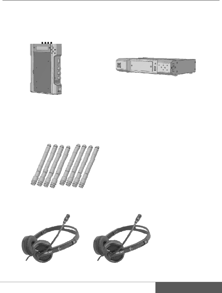
Packing
c
k the compo
n
CW‐F25T
X
p
plied acces
s
Readme Fir
Standard a
n
Headset ····
list
n
ents in the p
a
X
‐Tran sm it
t
s
ories
s
t
·········· x1
n
tenna ····· x8
············ x2
a
ckage.
t
er
CW-
F
F
25 RX - Rec
e
1
e
ive
r
1
1
12
5.
1)
1.
2.
3.
4.
5.
6.
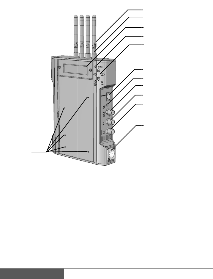
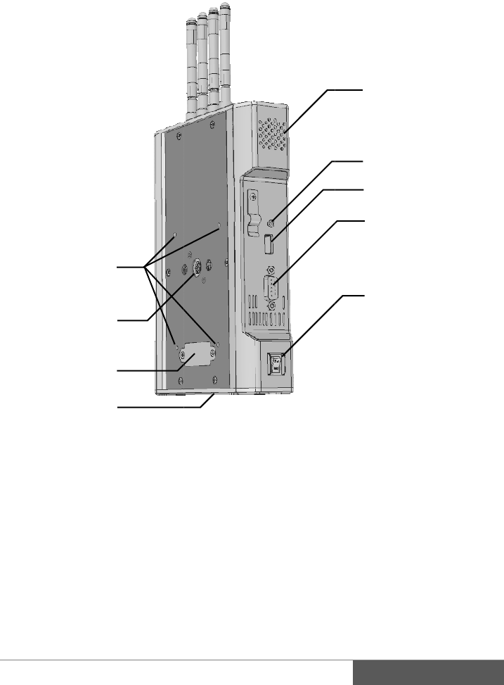
Names
o
TX - Trans
m
Antennas
Antenna c
o
RP-SMA
x
LCD
Display th
e
status.
Status LE
D
Menu setti
n
Move curso
r
ENTER,
E
Ethernet c
o
12
o
f parts
m
itter
o
nnecto
r
x
4
e
setup menu
D
n
g buttons
r
: Up, Down,
L
E
SC
o
nnecto
r
and
L
eft, Right
7. GPI
O
Cont
a
8. SDI
I
9. SDI
T
10. SDI
O
11. DC
p
XL
R
12. Scre
w
O
UT
a
ct closure o
u
I
N
T
HROUGH
O
O
UT
p
ower connec
t
R
-4 male
w
holes for
V
-
1
3
4
5
6
7
8
9
10
11
2
u
tpu
t
O
UT
t
o
r
-
Plate
13
14
15
16
17
18
. Ventilatio
n
. Intercom c
. USB conn
e
. RS-422 co
n
D-Sub 9
p
i
n
. Power ON
/
. Screw hol
e
plate
2
0
1
9
1
8
2
1
n
holes
onnecto
r
e
cto
r
n
necto
r
n
female
/
OFF switch
e
for
V
-Mou
n
0
9
8
1
n
t adopter
19. 3/8 i
n
20. Pow
e
for
V
21. 3/8 i
n
for t
r
(On
t
n
ch screw hol
e
r supply ter
m
V
-Mount adop
t
n
ch screw hol
r
ipo
d
t
he bottom)
13
14
15
16
17
1
e for tripod
m
inal in inside
t
er plate.
e
1
3
14
2)
1
.
2
.
3
.
4.
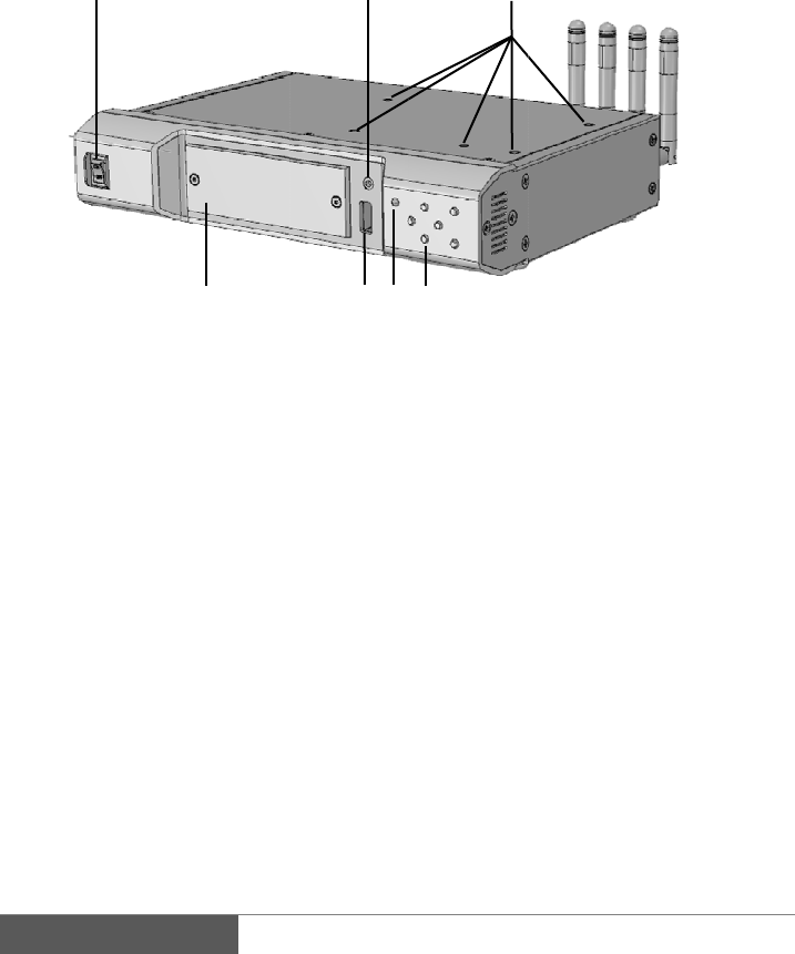
RX - Recei
v
.
Power ON
/
.
Intercom c
.
Screw hol
e
mounting
s
LCD
Display th
e
status.
1
v
er
/
OFF switch
onnecto
r
e
s for
V
-Plate.
s
crew holes
e
setup menu
4
and
2
65
5. USB
6. Stat
u
7. Men
u
Mov
e
ENT
E
3
7
connector
u
s LED
u
setting butt
o
e
curso
r
: Up, D
o
E
R, ESC
o
ns
o
wn, Left, Rig
h
h
t
8
.
9
.
1
0
1
1
1
2
.
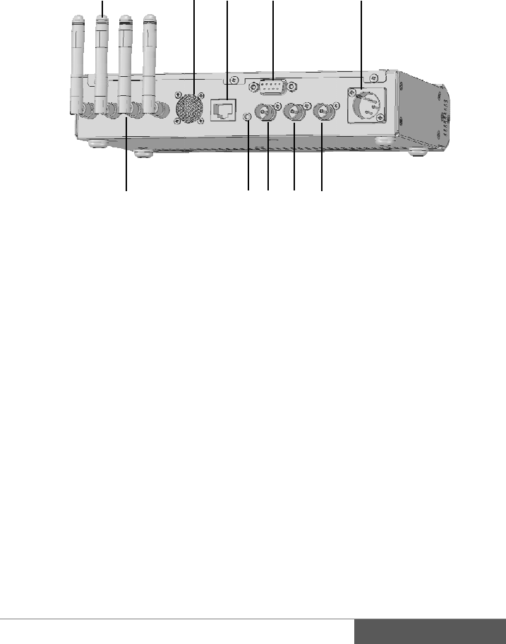
Antennas
.
Ventilatio
n
0
. Ethernet c
o
1
. RS-422 co
n
D-Sub 9
p
i
n
2
. DC
p
ower
XLR-4 ma
8
n
holes
o
nnecto
r
n
necto
r
n
female
connecto
r
le
13
910
14
1
13. Ante
n
RP-
S
14. GPI
I
Cont
a
15. SDI
I
16. SDI
T
17. SDI
O
11
1
51617
n
na connecto
r
S
MA x4
I
N
a
ct closure in
p
I
N
T
HROUGH
O
O
UT
12
1
r
p
u
t
O
UT
1
5
16
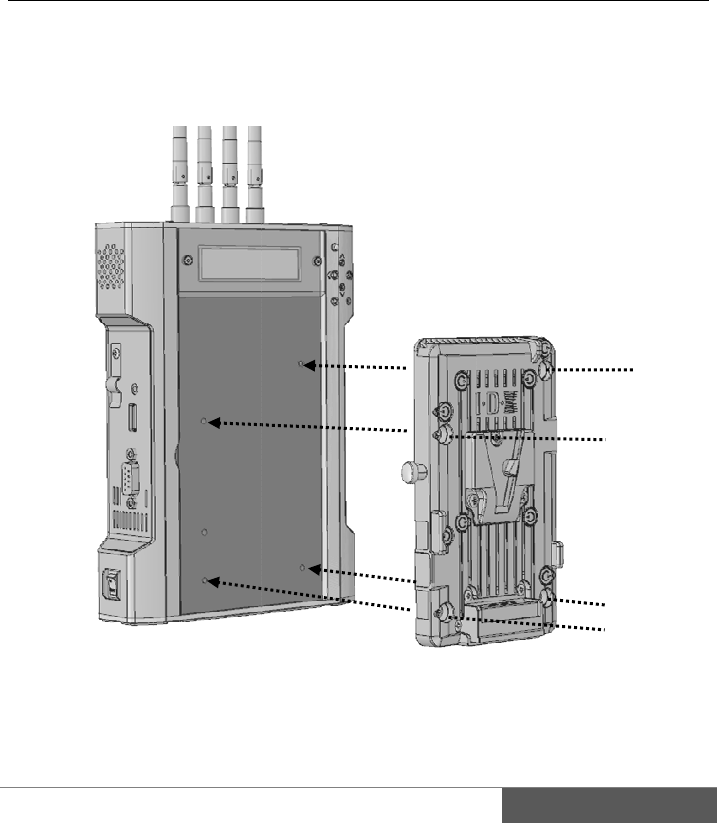
6.
V
T
I
V
T
t
B
s
t
e
H
A
P
*
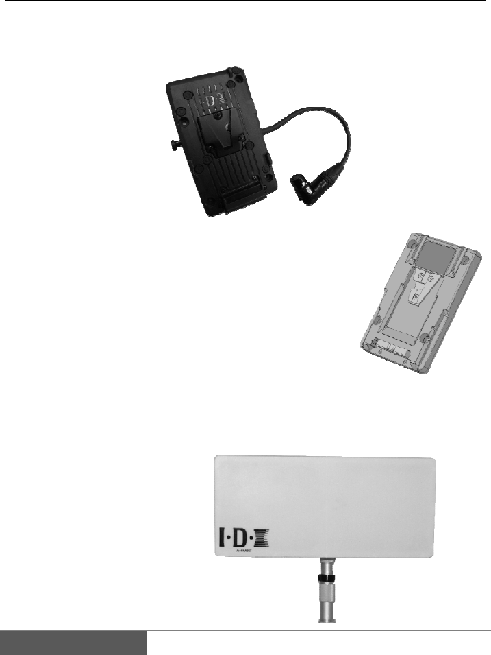
Optiona
l
V
-Plate
T
his plate ca
n
I
DX Endura
s
V
-Mount Ado
p
T
his adapter
p
t
hen the TX
c
B
y using thi
s
s
upplied to t
h
t
he plate. Th
e
e
ven if the po
H
igh-gain 4x
4
A
-4XANT is
P
ole mountin
g
*
Please prep
a
l
access
o
n
be mount o
n
s
eries Lithiu
m
p
ter Plate
p
late is for
m
c
an easily att
a
s
plate, the b
a
h
e camera thr
o
e
power will
wer OFF on
T
4
MIMO Ante
n
high-gain (1
8
g
bracket and
a
re the anten
n
o
ries
M
n
both TX a
n
m
Ion batteries
M
m
ounting on t
h
a
ch onto the
b
a
ttery or EXT
o
ugh the mul
t
continue su
p
T
X
n
na arra
y
M
8
dBi) directio
n
antenna cabl
e
n
a pole separa
t
M
odel# P-V2
C
n
d RX then s
u
.
M
odel# A-M
T
h
e back of t
h
b
ack of the ca
DC power c
t
i pin connec
t
p
ply to the c
a
M
odel# A-4
X
n
al antenna a
r
e
(3m x4) inc
l
t
ely.
C
L
u
pply +14V
D
T
2V
h
e TX
mera.
an be
t
or on
a
mera
X
ANT
r
ray.
l
uded.
D
C by attachi
n
n
g
II.
1.
This
1.
1
Mo
u
Prepar
a
Installat
i
section desc
r
1
. How t
o
u
nt the P-V2C
a
tion
i
on of op
t
r
ibes how to i
n
o
install the
L onto TX b
y
t
ional pla
n
stall the
V
-P
l
P-V2CL on
y
using suppli
e
tes
l
ate and V-M
o
to transmit
t
e
d screws as
s
o
un
t
adopter
p
t
e
r
s
hown in figu
r
1
p
late.
r
e above.
1
7
18
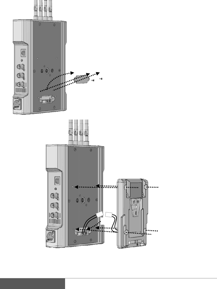
1.1.
How to i
n
n
stall the
A
-
①
-
MT2V onto
①
t
②
i
c
③
c
④
m
u
②
③
④
④
transmitte
r
①
Unscrew
t
hen remove t
h
②
Pull out
i
nside of tr
a
c
onnect with
c
③
Carefully
c
onnector to i
n
④
After rest
o
m
ount the A
-
u
sing supplie
d
④
④
r
on the bac
k
h
e metal cov
e
the power
c
a
nsmitter an
d
c
onnector fro
m
restore th
e
n
side of trans
m
o
re the cable
-
MT2V onto
d
screws, To i
n
k
of transmitt
e
e
r.
c
onnector fro
m
d
then firm
l
m
A-MT2V.
e
cable a
n
m
itte
r
.
and connect
o
transmitter
b
n
side of body.
e
r
m
l
y
n
d
o
r,
b
y
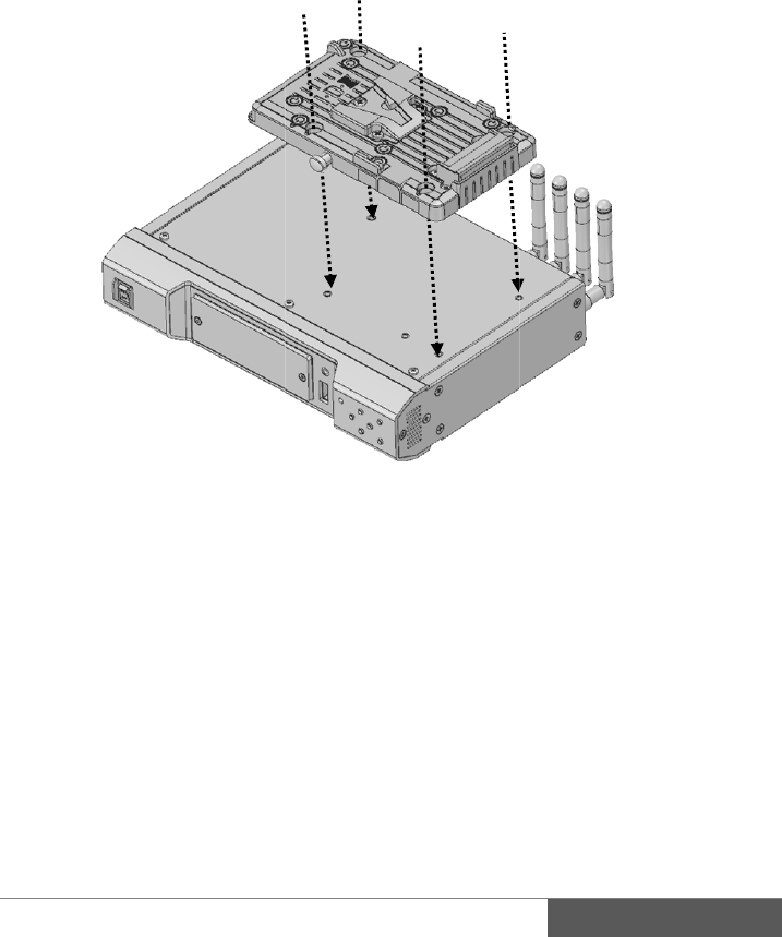
1.
2
Mo
u
2
. How to
i
u
nt the P-V2C
i
nstall the
P
L onto receiv
e
P
-V2CL ont
o
e
r by using s
u
o
receive
r
u
pplied screw
s
s
as shown in
1
figure above.
1
9
20
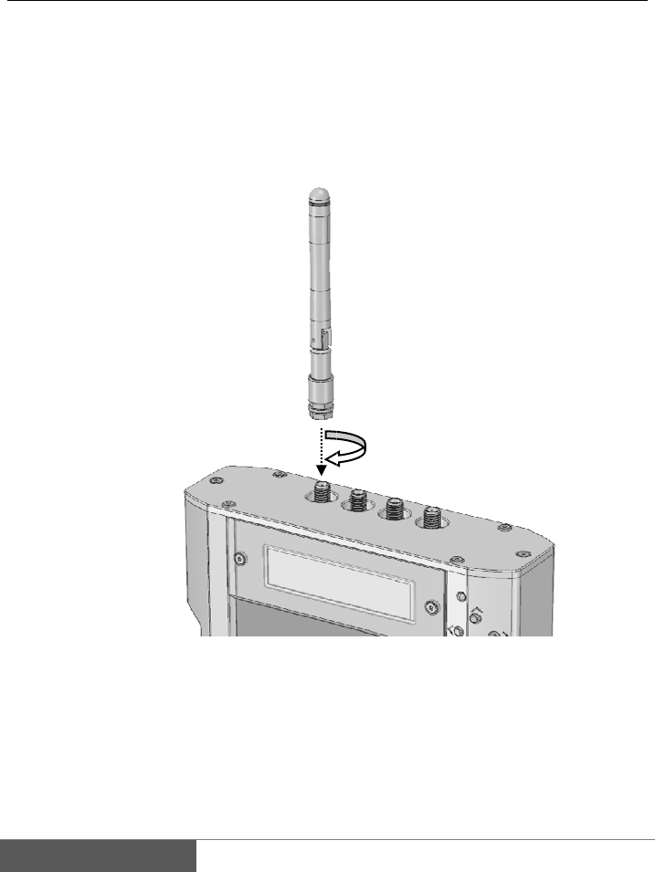
2.
2.
1
Tra
n
Atta
c
Installat
i
1
. Install t
h
n
smitter
c
h all four an
t
i
on of an
t
h
e antenna
t
ennas tightly
t
enna
mount in a c
l
l
ockwise dire
c
c
tion.
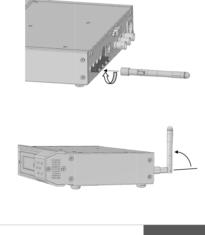
Rec
e
Atta
c
Sta
n
e
iver
c
h all four an
t
n
d up all the a
n
t
ennas tightly
n
tenna at 90
d
mount in a c
l
d
egree when i
n
l
ockwise dire
c
n
operation.
c
tion.
2
2
1
22
2.
2
A‐4
X
Inst
1.
A
2.
M
3.
C
C
Not
e
L
C
A
S
t
h
D
2
. Install t
h
X
ANTPac
k
Antenna
Coaxial ca
b
Pole mount
i
allation
A
ttach the bra
c
M
ount the ant
e
C
onnect four
C
W-F25.
e
L
ength of co
a
C
oaxial cable
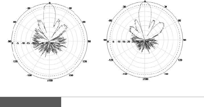
A
-4XANT is
a
S
ignal strengt
h
h
en transmiss
D
irectivity of
t
Ver
t
h
e optional
k
inglist
b
le 3m/10 feet
i
ng bracke
t
c
ket firmly o
n
e
nna to the p
o
N-type con
n
a
xial cable is
3
longer than 3
m
a
directional
a
h
falls if direc
ion may not
b
t
he antenna i
s
t
ical surface
antenna
x1
x4 (N
x1
n
to the anten
n
o
le.
n
ectors to th
3
m/10 feet.
m
is not reco
m
a
ntenna.
tion of the an
t
b
e performed
p
s
as follows
-plug / RP-S
M
n
a.
e antenna a
n
m
mended due
t
enna surface
p
roperly.
Ho
r
MA
plug)
n
d another s
i
to attenuatio
n
is displaced,
r
izontal surfa
c
i
de connect
t
n
of the signa
l
c
e
t
o
l
.

23
3. Preparing for power supply
AC adapter is not included to the package. Recommended power supply for the
CW-F25 shown in below.
3.1. Recommended products
AC adapter IDX IA-60a IA-200a IA-300a AC-100
Power base station IDX EB-2 EB-4 EB-424L
Batteries IDX Endura series battery with optional P-V2CL.
3.2. Note
P-V2CL is an adopter for V-Mount batteries.
Input voltage range is DC 7V to 17V.
Power input connecter is Cannon 4-pin male.
Pin assignment #1: minus (-)
#4: plus (+)
Caution
Please make sure the input voltage range.
Please be careful not to reverse connection of power supply.
Useable battery is 7.4V lithium-ion battery or 14V lithium-ion battery. 24V battery
cannot be used.
24
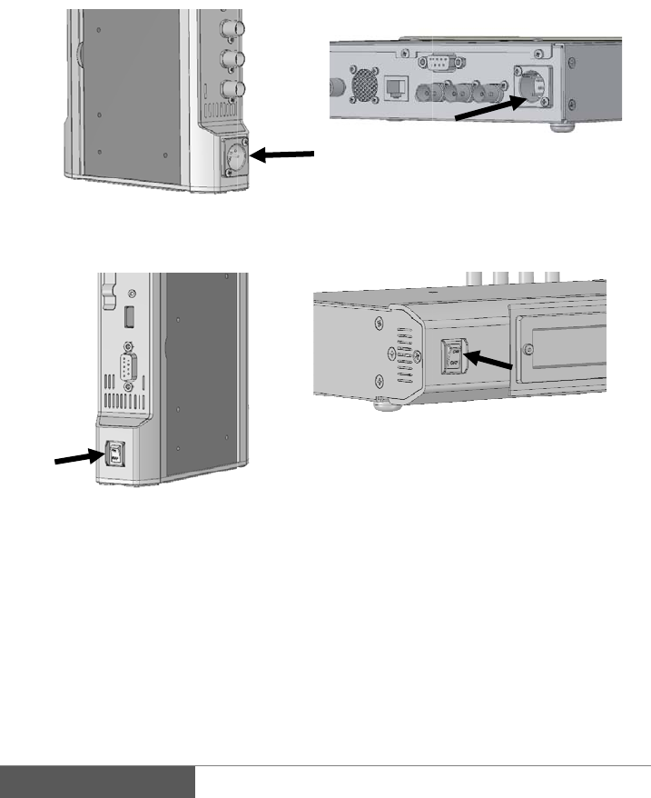
3.
3
1)
2)
3)
4)
3
. Power
o
Connecting
t
Plug the Ca
n
* Insert tigh
t
Tran
s
Turn on the
p
Trans
m
LCD backli
g
LCD will st
a
will starts fl
a
Turn off the
p
Turn OFF th
o
n and Po
w
t
he power su
p
n
on connector
t
ly until it cli
c
s
mitter right s
i
p
ower switch
m
itter left side
g
ht will turn o
n
a
rt to display
i
a
shing GREE
N
p
ower:
e power swit
c
w
er of
f
p
pl
y
to the DC in
p
c
ks.
i
de
n
then status
L
i
nformation a
b
N
.
c
h then remo
v
p
ut on TX an
d
Rece
i
Rece
i
L
ED lights R
E
b
out 15 seco
n
v
e the power
c
d
RX.
i
ver backside
i
ver fron
t
E
D.
n
ds later then
c
able.
the status LED
25
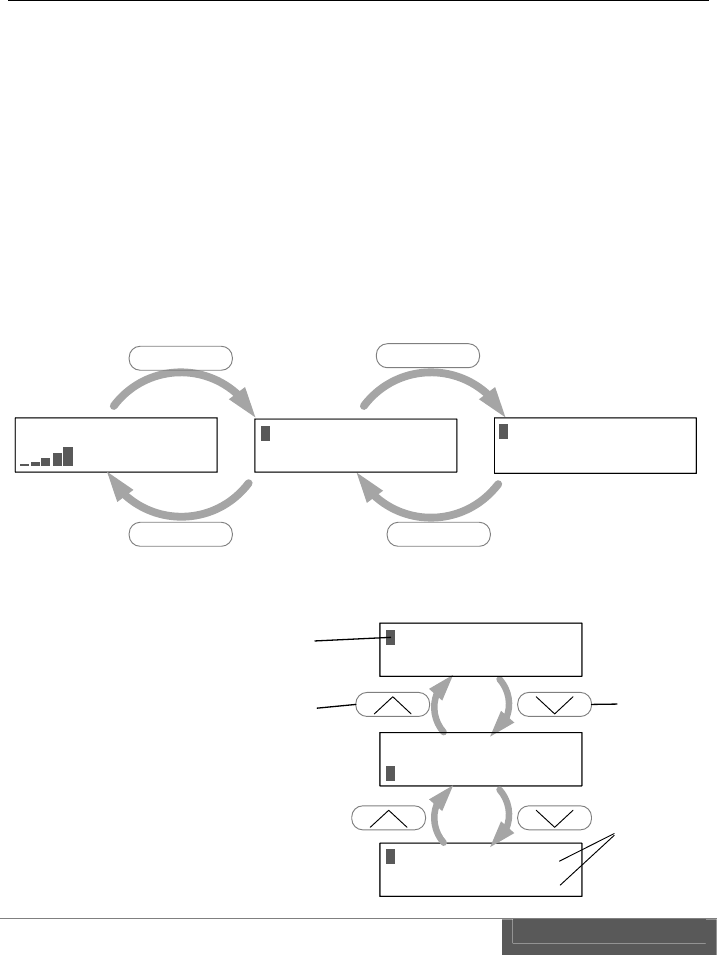
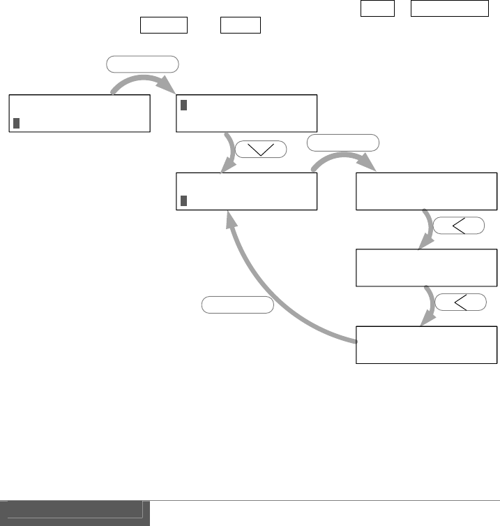
Menu: Level 1
Wi r el ess set up
Network setup↓
Wi r el ess set up
Network setup↓
Ne t wo r k s e t u p ↑
Video ↓
Cursor
Up button Down button
Arrow:
It indicates that the
menu is followed by up
or down as scroll.
4. Menu setting
CW-F25 equipped operation button and LCD for displays current status and for menu
setting. This section describes how to operate the button and information that displays
on LCD .
4.1. LCD and the push button
LCD displays setup menus and current status.
By pressing ENTER button, display can be changed from current status to menu
setting mode. Setup menu is hierarchical thus the role of the ENTER button is to use
for item selection and move down to the lower level.
Role of ESC button is moved back to the upper level and it can be returned to the
status display on the top. See below.
Cursor appears in the
menu and move up or
down the cursor by
using Up or Down
button.
(See the right)
1080i / 59. 94 300M
25M 34. 5dB
ENTER
ESC ESC
ENTER
Information Display Menu: Level 1 Menu: Level 2
Wireless setup
Ne t wo r k s e t u p ↓
Channel f r eq.
Channel power ↓
26
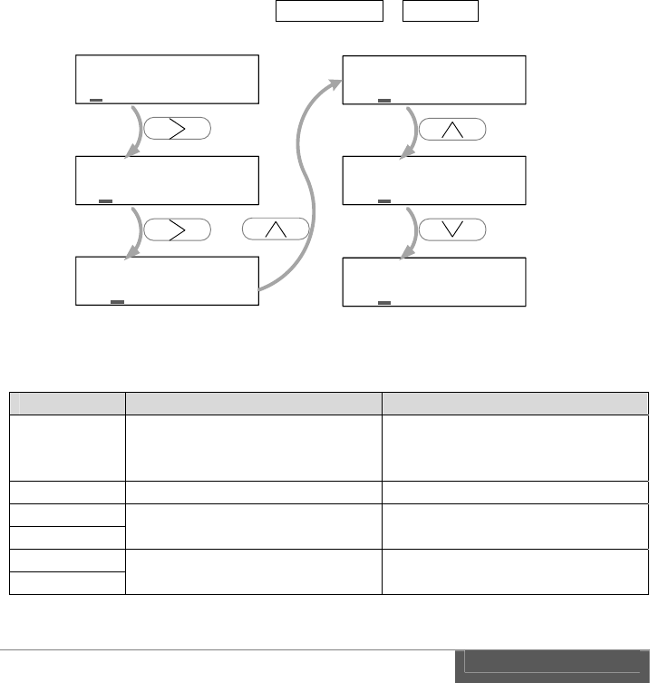
Select the menu by using ENTER button and then move to the lower level. Select the
menu by scrolling cursor then move to the setting item by pressing ENTER button.
Menu will indicate possible selection in the setup items Move the item by left or right
button, then press ENTER for selecting desired item.
ESC means the cancel. If pressed ESC button, it will return to upper level with
keeping previously selected item.
Example;
For changing video bit rate, move down the menu hierarchy Video > Video bit rate,
then it been changed to 20Mbps from AUTO.
Net wor k set up↑
Video ↓
H. 264 pr of i l e
Vi deo bi t r at e↓
H. 264 pr of i l e
Vi deo bi t r at e↓
Vi deo bi t r at e
← AUTO
Vi deo bi t r at e
← 25 Mbps →
Vi deo bi t r at e
← 20 Mbps →
Menu: Level 1 Menu: Level 2
Setting items
ENTER
ENTER
ENTER
27
Some of the setting items need to enter a numerical number or alphabet.
To move the cursor to digit by left or right button and then select alphabet by up or
down button.
Continue to move the cursor to another digit by left or right button, then please enter
all the necessary character. Press ENTER when all the input has been completed.
Press the ESC if you want to cancel the input.
Example;
For changing Network IP address. Network setup > IP address.
Summarizes the role of the operation button in the table below.
Button Behavior in the menus Behavior in the setup items
ENTER Display the menu.
Select menu items
down to next level. Commit for changes.
ESC Go back to upper level. Cancel
Up Move cursor. Select character.
Down
Left - Move between setting items.
Move cursor.
Right
IP address
192. 168. 098. 100
IP address
192. 168. 098. 100
IP address
192. 168. 098. 100
IP address
193. 168. 098. 100
IP address
194. 168. 098. 100
IP address
193. 168. 098. 100
28
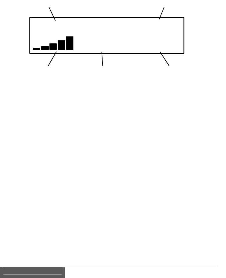
4.2. Information display
LCD displays a status of the video transmission as shown in below.
1. Video format
Display the resolution and frame/field rate of input video.
Display the "NO_VIDEO_IN" if there is no input signal of SDI.
2. Wireless link speed
Display the wireless link speed of current connection.
"300M" indicates that the link speed is 300Mbps and this is a maximum speed of
the 802.11n.
3. Received signal strength
Display in five steps bar the strength of the received signal. The strength of the
received signal will display by five steps bar.
When the number of the bar is greater, it indicate that is in good receiving
condition.
4. Video bit rate
Display a current H.264 video bit rate.
When the bit rate set to "AUTO" mode, '*' mark will appear in front of the
number.. Video bit rate indication will updated accordingly due to the
transmission state.
5. SNR (Signal Noise Ratio)
Display the S/N ratio of receiving radio waves.
It indicate a good receiving condition if value is greater.
1080i / 59. 94 300M
25M 34. 5dB
1 2
3 45

29
4.3. Default settings
CW-F25 has shipped with default setting that enable for immediate use, however,
please be sure to check the frequency every time prior to use.
Transmitter only - setting the radio frequency
Please select and set at desired frequency.
Menu: Wireless setup > Channel freq.
Other settings may be set as required.
For more information about settings, please refer to P.51 "References".
30
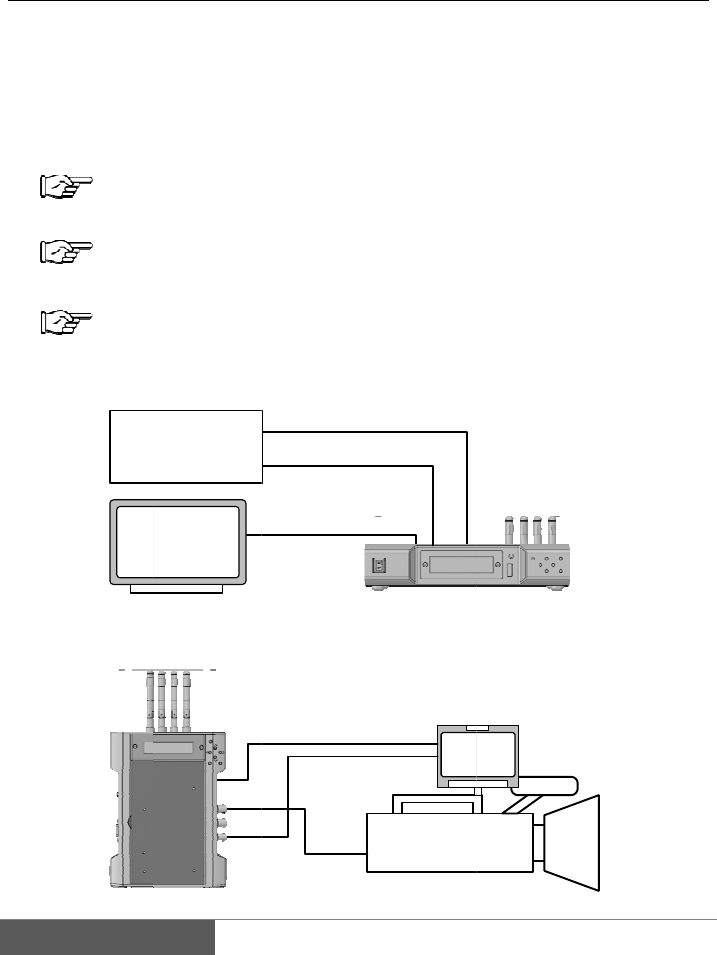
III.
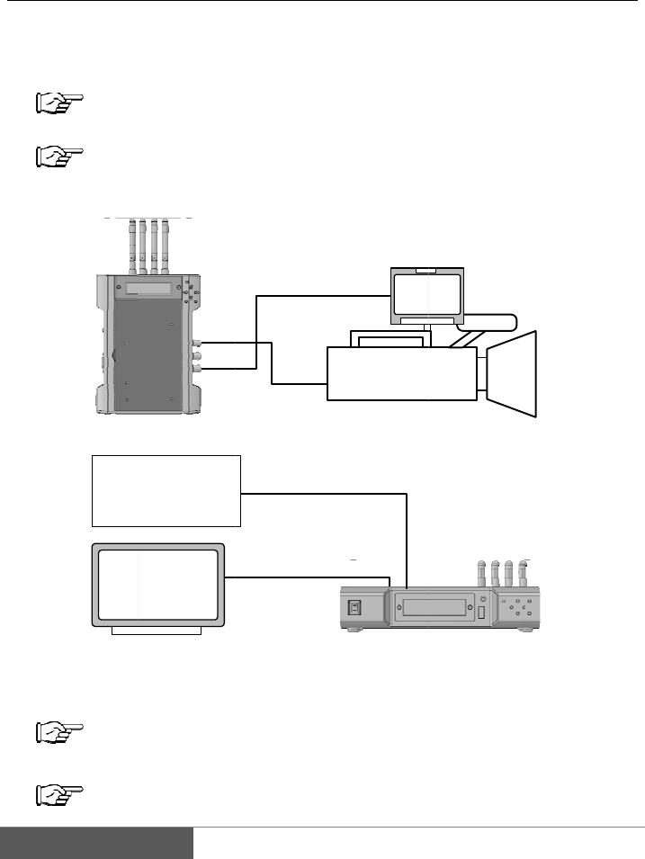
1.
In t
h
vide
o
For
m
1.
2.
3.
Operat
i
Basics
h
is section, it
i
o
.
m
ore informa
t
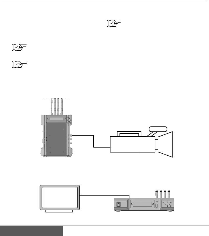
Install the a
n
P.20 "I
n
Connection
o
P.23 "P
r
Connect bet
w
Connect bet
w
i
on of C
i
s explained
a
t
ion about set
t
n
tennas to tra
n
n
stallation of
a
o
f power sup
p
r
eparing for
p
w
een camera
a
w
een monitor
SD
I
Monitor
W-F25
a
bout basic vi
t
ing, refer to
n
smitter and r
e
a
ntenna"
p
ly to transmi
t
p
ower supply"
a
nd transmitt
e
and receiver.
I
-IN
SDI-
O
U
T
SDI-IN
deo transmis
s
mark.
e
ceiver.
t
ter and recei
v
e
r.
T
Came
r
SDI-OUT
s
ion. Let's tra
n
v
er.
r
a
n
smit downli
n
n
k

4.
5.
6.
Turn the po
w
P.24 "P
Set the freq
u
P.52 "S
If the conn
e
monitor.
Note:
If you select
of waiting ti
m
w
er ON of tra
n
ower on and
P
u
ency in a set
u
etup menus -
e
ction succes
the radio fre
q
m
e. One min
u
n
smitter and r
P
ower off"
u
p menu of tr
a
Transmitter"
sful, the tra
n
q
uency of D
F
u
te of waiting
eceiver.
a
nsmitter.
n
smitted vide
o
F
S, signal wil
l
time is strict
r
o
will be di
s
l
link after ab
r
ule of DFS f
r
3
s
played on t
h
out one minu
r
equency use.
3
1
h
e
te
32
2.
CW
-
7.
1.
2.
3.
4.
Return
v
-
F25 is capab
l
Install the a
n
P. 20 "I
Connection
o
P.23 "P
r
Camera and
Turn the po
w
P.24 "P
Set the freq
u
P.52 "S
M
Re
t
s
v
ideo
l
e to transmit
t
n
tennas to the
nstallation of
o
f power su
p
r
eparing for
p
monitor setu
p
w
er ON of tra
n
ower on and
P
u
ency in a set
u
etup menus -
SDI-I
SDI-
O
S
M
onitor
t
urn video
s
ource
t
he return vid
e
transmitter a
n
antenna"
p
ply to trans
m
p
ower supply"
p
shown in be
l
n
smitter and r
P
ower off"
u
p menu of tr
a
Transmitter"
N
SDI-OUT
O
UT
S
DI-IN
S
SDI-OUT
e
o as well.
n
d receiver.
m
itter and rec
e
l
ow.
eceiver.
a
nsmitter.
Camer
a
Mo
n
SDI-IN
S
DI-OUT
SDI-IN
e
ive
r
.
a
n
itor

5.
6.
Enable the r
e
Video > Ret
u
Video > E
m
video is not
r
* Factory de
f
P.60 "S
The last sett
i
If the conne
c
the return vi
d
e
turn video in
u
rn Video >
O
m
bedded Aud
i
r
equired.
f
aul
t
setting i
s
etup menus -
i
ng is memori
z
c
tion success
f
d
eo will displ
a
a setup men
u
O
N
i
o > ON
P
s
both ON.
Receiver"
z
ed even afte
r
f
ul, the down
l
a
y on the mo
n
u
of receiver.
P
lease select
r
power turne
d
l
ink video wil
n
itor of came
r
OFF If audi
o
d
OFF.
l display on t
h
r
a side.
3
o
in the retu
r
h
e monitor a
n
3
3
r
n
n
d
34
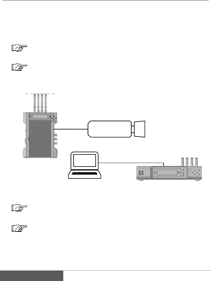
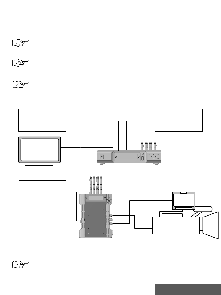
3.
Eth
e
the
E
An
e
1.
2.
3.
4.
5.
6.
IP cam
e
e
rnet on the C
W
E
thernet term
i
e
xample of IP
Install the a
n
P. 20 "I
Connection
o
P.23 "P
r
IP camera c
o
terminal on
t
Turn the p
o
P.24 "P
Set the radi
P.52 "S
When the
w
controlling I
P
e
ra setup
W
-F25 works
i
nal on the C
W
camera setup
n
tennas to the
nstallation of
o
f power sup
p
r
eparing for
p
o
nnect to the
t
he receiver c
o
o
we
r
ON of tr
a
ower on and
P
o frequency i
n
etup menus -
w
ireless link
i
P
camera fro
m
Etherne
t
- wireles
as a wireless
W
-F25 will fu
n
.
transmitter a
n
antenna"
p
ly to transmi
t
p
ower supply"
Ethernet ter
m
o
nnect to PC.
a
nsmitter and
P
ower off"
n
a setup me
n
Transmitter"
i
s established
m
PC.
PC
IP c
a
t
s LAN b
r
LAN bridge.
n
ction as con
n
n
d receiver.
t
ter and recei
v
m
inal on the
t
For example
b
receive
r
.
n
u of transmit
t
firmly, vide
o
a
mera
r
idge -
All the devic
e
n
ected directl
y
v
er.
t
ransmitter, a
n
b
elow.
t
e
r
.
o
transmissio
Ethernet
e
s connected
t
y
to the LAN.
n
d the Ethern
n
will start
b
t
o
et
b
y
35
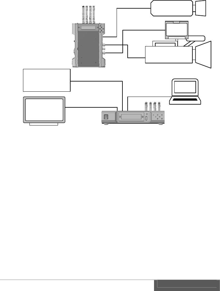
SDI-IN
SDI-OUT
Camera
Monitor
SDI-OUT
SDI-IN
IP camera
Ethernet
SDI-IN SDI-OUT
Monitor
Return video
source
SDI-IN
SDI-OUT
PC
Ethernet
Wireless LAN bridge function can be used at same time as transmission of downlink
video and return video.
Note:
Downlink and return video has a priority in the wireless transmission while
Ethernet data communication has low priority. Therefore it is recommended to
apply lower frame rate and lower video resolution on IP camera when operate
both SDI and Ethernet. Specific value is depending on a transmission distance
and operational environment, therefore, it is recommended for performance test
prior to use.
Ethernet interface is not supported PoE (Power Over Ethernet). Please prepare a
separate power for IP camera and other Ethernet device.
CW-F25 has no DNS and DHCP server. Therefore please assign a static IP
address to IP camera and other Ethernet device or prepare a separate DNS and
DHCP server.
Please do not connect the Ethernet terminal of transmitter and receiver to
existing LAN network. CW-F25 may be act as wireless LAN bridge. Ethernet
topology loop occurs when the transmitter and receiver connected to the same
LAN. Ethernet topology loop will cause the fault such as degradation of
performance and network down, etc..
36
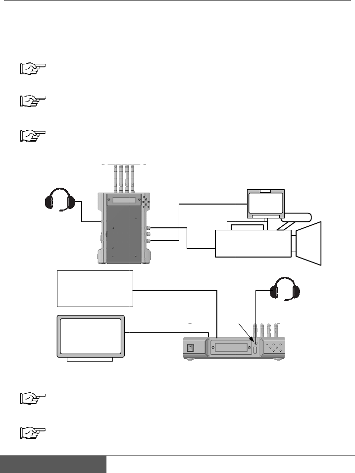
4.
By
u
rece
i
1.
2.
3.
4.
5.
6.
Headset
I
M
R
e
Interco
m
u
sing a hea
d
i
ver.
Install the a
n
P. 20 "I
Connect of
p
P.23 "P
r
Camera an
d
P.30 "
B
Connect the
Turn the po
w
P.24 "P
Set the radio
P.52 "S
NTERCOM
S
M
onitor
e
turn video
source
m
operati
o
d
set, voice c
o
n
tennas to the
nstallation of
p
ower supply
t
r
eparing for
p
d
monitor set
u
B
asics", P.32 "
R
headset to tra
n
w
er ON of tra
n
ower on and
P
frequency in
etup menus -
SDI-IN
SDI-OUT
S
DI-IN
S
SDI-OUT
o
n
o
mmunicatio
n
transmitter a
n
antenna"
t
o transmitter
p
ower supply"
u
p, etc..
R
eturn video
"
n
smitter and
r
n
smitter and r
P
ower off"
a setup men
u
Transmitter"
SDI-OUT
SDI
-
DI-OUT
SDI-IN
I
NT
E
n
is possible
n
d receiver.
and receiver.
"
r
eceiver.
eceiver.
u
of a transmit
t
Camera
Monitor
-
IN
H
ead
s
E
RCOM
in between
t
t
er.
s
et
t
ransmitter a
n
n
d

37
7. Enable an intercom in the setup menu of transmitter and receiver.
Intercom > Intercom > ON
* Default setting is ON..
Last setting is memorized even after power is turned OFF.
8. CW-F25 is able to talk through the headsets on both transmitter and receiver.
Volume control
Sound and microphone volume can be set in the menu.
Sound volume
Intercom > Phone level > 0 to 10 , 0 is minimum. 10 is maximum.
Microphone volume
Intercom > Mic Level > 0 to 10, 0 is minimum. 10 is maximum.
Using another headset
Intercom jack is CTIA compliant 4-pole mini jack. Please check the pin assignment
prior to use the headset on the market.
Please refer to P.75 "Connector and pin assignment" for pin assignment.
38
5.
GPI
GPI
outp
GPI
1.
2.
3.
4.
5.
GPI con
input is loca
t
signal feed t
o
u
t
.
output, also,
c
Install the a
n
P. 20 "I
Connect th
e
P.23 "P
r
Camera and
P.30 "
B
Connect a c
o
For example
Connect the
For example
M
Vid
e
nection -
t
ed on the rec
o
the receive
r
,
c
an be used a
s
n
tennas to tra
n
nstallation of
e
power supp
l
r
eparing for
p
monitor setu
p
B
asics", P.32 "
R
o
ntact closure
below.
transmitter a
n
bellow.
S
M
onitor
e
o switcher
SDI-
I
SDI-
O
GPI
as tally
eiver and GP
I
,
will transmi
t
s
wireless co
n
n
smitter and r
e
antenna"
l
y to transmit
t
p
ower supply"
p
, etc..
R
eturn video
"
output from
t
n
d tally LED
u
S
DI-IN
SD
SDI-OUT
GPI OUT
I
N
SDI-OUT
O
UT
OUT
I
output is lo
c
t
to the trans
m
n
nection statu
s
e
ceiver.
t
er and receiv
e
"
t
he switcher t
o
u
nit or a moni
D
I-OUT
SDI-IN
GP
Came
r
Mo
n
SDI-IN
GPI IN
c
ated on the t
m
itter, then o
u
s
output by se
t
e
r.
o
receiver.
tor which has
P
I IN
r
a
n
itor
r
ansmitter. T
h
u
tputs from G
P
t
ting menu.
tally input.
h
e
P
I
6.
7.
8.
9.
Ca
b
GPI
Plea
Plea
Turn the p
o
P.24 "P
Set the radio
P.52 "S
Setting the
G
Tally > Tall
y
Each functi
o
Remote
Link Status
* Default se
t
Last setting
i
Setting GPI
f
Tally > Re
m
ON means a
* Default se
t
Last settin
g
b
le and conn
e
connector is
t
se refer P. 75
se prepare G
P
o
wer ON of tr
a
ower on and
P
frequency in
etup menus -
G
PI function i
n
y
mode > Re
m
o
n described a
s
Contact si
g
output fro
m
Contact si
g
Output th
e
Disconn
e
Waiting:
Connect
t
ting is Remo
t
i
s memorized
f
unction in th
e
m
ote Tally >
O
GPI input is
e
t
ting is ON.
g
is memorize
d
e
ctor
t
wo-
p
ole min
i
"Connector a
n
P
I cable, local
l
a
nsmitter and
P
ower off"
the setup me
n
Transmitter"
n
the setup m
e
m
ote or Link
S
s
follows.
g
nal input to
t
m
transmitter.
g
nal means;
o
e
state of the
w
e
ct: open,
open/short a
l
: short.
t
e.
even after po
w
e
settings me
n
O
N or OFF
S
e
nable. OFF i
d
even after p
i
jac
k
.
n
d pin assign
m
ly
.
receiver.
n
u of transmi
t
e
nu of transm
i
S
tatus Select
o
t
he receiver
w
o
pen=off / sh
o
w
ireless conn
e
l
ternately (fla
s
w
er is turned
n
u of receiver
.
S
elect one.
s disabled.
ower is turne
d
m
en
t
".
t
ter.
i
tter.
o
ne.
w
ill be transm
i
o
rt=on.
e
ction.
s
hing),
OFF.
.
d
OFF.
3
i
tted and
3
9
40
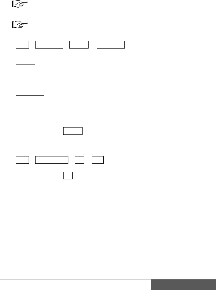
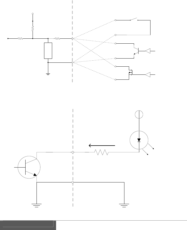
Equivalent circuit of the GPI input of receiver
GPI input is a non-voltage contact.
Equivalent circuit of the GPI output of transmitter.
GPI output is an open collector.
VCC
Tally
LED
Max 24V
Max 40mA
COMMON
GND
Open collector
output
GPI OUT
CW-F25 TX
GPI OUT
External Equipment
Vcc
3.3V
CW-F25 RX
GPI IN External Equipment
GPI IN
COMMON
GND
Simple Switch
Open collector
MOSFET
Protection
device
10Kohm
10Kohm
4.7Kohm
6.
CW
-
It m
a
1.
2.
3.
4.
5.
RS-422
-
F25 works a
s
a
de possible t
h
Install the a
n
P. 20 "I
Connect the
P.23 "P
r
Camera an
d
P.30 "
B
Connect the
Turn the po
w
P.24 "P
Monit
o
Return
v
sour
c
RS-422
d
(B)
remote
s
a media con
v
h
e wirelessly
n
tennas to tra
n
nstallation of
power suppl
y
r
eparing for
p
d
monitor set
u
B
asics", P.32 "
R
RS-422 devi
c
w
er ON of tra
n
ower on and
P
SDI-IN
o
r
v
ideo
c
e
SDI-
O
d
evice
RS-422
v
erter for bet
w
connections
o
n
smitter and r
e
antenna"
y
to transmitte
r
p
ower supply"
u
p, etc..
R
eturn video
"
c
e to transmit
t
n
smitter and r
P
ower off"
SDI-OUT
SDI-
I
O
UT
SD
SD
G
w
een RS-422
a
o
f between R
S
e
ceiver.
r
and receive
r
"
t
er and receiv
e
eceiver.
I
N
RS-422
D
I-IN
SDI-
OU
D
I-OUT
G
PI OUT
a
nd wireless
L
S
-422 devices
.
r
.
e
r.
RS422
(
A
U
T
Cam
e
M
o
SDI-IN
4
L
AN.
.
device
A
)
e
ra
o
nitor
4
1
42
6.
7.
8.
9.
RS-
4
RS-
4
Plea
Plea
Not
e
The
r
dela
y
test
p
Set the radio
P.52 "S
Enable the
R
Remote > I
n
* Default se
t
Last setting
i
Set a comm
u
Remote > B
a
Remote > D
Remote > P
a
Remote > S
t
Last setting
i
CW-F25 set
u
4
22 cable a
n
4
22 connecto
r
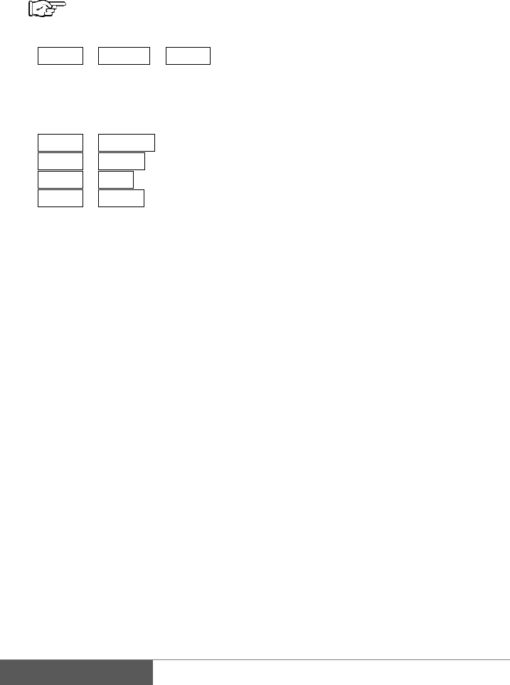
se refer P. 75
se prepare R
S
e
r
e is a trans
m
y
is dependin
g
p
rior to use t
h
frequency in
etup menus -
R
S-422 interfa
n
terface > RS
-
t
ting is OFF.
i
s memorized
u
nication para
a
ud rate > Se
l
ata bit > Sele
c
a
rity > Select
t
op bit > Sele
c
i
s memorized
u
p successful
n
d connecto
r
r
is a D-Sub 9
"Connector a
n
S
-422 cable, l
o
m
ission delay
g
on environ
m
h
e system.
the settings
m
Transmitter"
ce in the setu
p
-
422
even after po
w
meters of RS
-
l
ect baud rate
.
c
t data bit len
g
parity.
c
t stop bit len
g
even after po
w
then the two-
w
r
pin female.
n
d pin assign
m
o
call
y
.
occurs beca
u
m
ent and tran
s
m
enu of trans
m
p
menu of rec
w
er is turned
-
422 in the se
t
.
* De
f
g
th. * De
f
* De
f
g
th. * De
f
w
er is turned
w
ay transmis
s
m
en
t
".
u
se of in rad
s
mission dist
a
m
itter.
eiver.
OFF.
t
ting menu of
f
ault is 56250
0
f
ault is 8 bit.
f
ault is "none
"
f
ault is 1 bit.
OFF.
s
ion of RS-42
io transmissi
o
a
nce therefor
e
receiver.
0
bps.
"
.
2 is started.
o
n. Amount
o
e
recommend
t
o
f
t
o

43
IV. Useful information
1. Troubleshooting
Check the following before asking for a repair. If the problem is not resolved then
please contact to the dealer or our support & service. Please refer to P.82 "Support &
Service contact".
1) Power does not turn on
Check the lighting of the status LED. If it is lit or flashing means that the power it
turned ON. There is a possibility of a failure if the LCD backlight is not lit when the
LED is flashing or lit.
Please be make sure whether input correct voltage.
Voltage range of CW-F25 is DC7-17V.
Is power supply or AC adapter turned ON?
Is AC adapter connected to a commercial power source correctly
Has the battery remained enough capacity and nominal output voltage?
Is A Battery mounted onto P-V2CL correctly? A battery must mount straightly from
the upper side of the V-plate. Insufficient handling of battery will be causing serious
damage to the pin of V-plate.
Isn't connection of Cannon pin reverse?
Pin assignment of Cannon XLR-4 is: #1 = minus, #4 = plus.
Is Cannon connecter inserted until it's firmly locked?
When installing the A-MT2V, make sure the connection of both connectors are
firmly plugged in. And, then, carefully mount and screw by confirming not to pinch the
wires in between the A-MT2V and CW-F25.
2) Status LED does not lit
Please check the power supply. Refer P.43 "Power does not turn on".
Status LED starts to lit about 15 second later after the power turned ON. This time
delay caused by the circuit initialization time, and this is not a malfunction.

44
3) LCD backlight does not lit
Please check the power supply. See the P. 43 "Power does not turn on".
LCD backlight will lit immediately after power turned ON and it is always lit during
operation. It is a failure if the LCD backlight is not lit.
4) Does not connect the wireless
Please check LED status.. Red LED lit during initialization of the system, Green LED
flashing indicates state of waiting, and Green LED lit when the system has connected
successfully. If the video signal is not transmitted even when the Green LED lit.
Please refer P.45 "No video out".
Please reboot the power once if a status LED is not changed to Green for more than
one minute. It is a system failure if this situation has not recovered after reboot of
power.
If selected Indoor DFS or Outdoor DFS, in the setup menu, the system automatically
goes into standby state for about 1 minute for searching an official radio waves.
During DFS searching state, status LED is flashing green.
Please check if antennas are firmly connected. It may be loosen while in use.
Isn’t a distance between transmitter and receiver too close?
In case of standard antenna operation, recommend the distance more than 3m.
In case of directional antenna array operation, recommend the distance more than 5m.
Is the directional antenna array setting confront correctly? Antenna cannot transmit or
receive the radio waves on the back or the widthwise.
Isn't distance too far in between the antennas? Please re-try by reducing the distance.
Isn't there any radio wave shielding object in between the antennas? Obstacles which
were made by concrete, metal and glass with electromagnetic shielding will be
causing disturbance or blocking of radio waves.
Transmission path will be affected by the surrounding buildings, obstacles and
environment, therefore there are places where radio waves is weak in spite of short
distance.
Isn't 5GHz wireless LAN used by neighborhood? Wireless LAN can be co-exist even
if there is another wireless been used, but may not be able to connect if the frequency
is overlapped. Please try with other frequency.

45
Isn't there a source of powerful electric wave nearby? Wireless connection in the area
where close to the powerful radio sources is difficult. This is because the receiving
sensitivity of the receiver is reduced, even if using a different frequency band. Please
use away from these area.
Is SSID setting on transmitter and receiver same? It is not possible to connect if the
SSID setting were different. *Same SSID is set at factory.
Is password setting on transmitter and receiver same? It is not possible to connect if
the password setting were different. *Same password is set at factory.
Please check the following item when IP address has changed.
・Subnet must be same. Please check the Netmask.
・IP address must not conflicts.
Please Check the IP Address and the Codec Local IP .
・Codec Local IP of transmitter and Codec Remote IP of receiver must be the same.
Receiver attempts to connect to an address set in Codec Remote IP. Please check
when change the IP address.
For details, please refer P.52 "Setup menus - Transmitter" & P.60 "Setup menus -
Receiver".
5) No video out
Please check the SDI connection.
Transmitter:
Output of return video is 'SDI OUT' connector.
Output of loop-out is 'SDI THRU OUT' connector.
Receiver:
Output of downlink video is SDI OUT connector.
Output of loop-out is 'SDI THRU OUT' connector.
Input of return video is 'SDI IN' connector.
Please confirm the video format whether it is supported by the system. It is not
possible to transmit if it was an unsupported video format.
Please refer P.69 "Specification".
Video input and output are SDI only. This product does not support an analog signal.
Please check the camera settings. Is SDI output enabled?
Please check the settings of monitor. Is input selection correct?
Please check coaxial cable. Isn’t cable broken? Isn’t cable length too long? Is the
video output if changed cable?

46
6) No audio out
If the embedded audio of downlink video is not output, please check Embedded
Audio setting of transmitter. Is it turned ON?
If the embedded audio of the return video is not output, please check Embedded
Audio setting of receiver. Is it turned ON?
The SDI embedded audio is supported 4CH in the downlink. (Group 1)
The SDI embedded audio in the return video is supported 2CH. (Group 1)
CW-F25 supports only SDI embedded audio. It does not supports an analog audio
and AES/EBU.
7) Video interruption & disturbance
Please check the video rate setting. It is required more channel capacity when set at
high bit rate. Reduce the setting of bit rate or set it to AUTO bit rate.
Video block noise and/or drop frame will occur if there is no sufficient channel
capacity available that causing by the interference and distance.
Video distortion or blackout occur if the input video format is changed during
transmission.
Video will freeze temporarily if the H.264 profile is changed during transmission.
Isn't there any radio wave shielding object in between? Obstacles which were made by
concrete, metal and glass with electromagnetic shielding will be causing disturbance
or blocking of radio waves.
Transmission path will be affected by the surrounding buildings, obstacles and
environment, therefore there are places where radio waves is weak in spite of short
distance.
Isn't 5GHz wireless LAN used by neighborhood? Wireless LAN can be co-exist
even if there is another wireless been used, but may not be able to connect if the
frequency is overlapped. Please try with other frequency.
Isn't there a source of powerful electric wave nearby? Wireless connection in the area
where close to the powerful radio sources is difficult. This is because the receiving
sensitivity of the receiver is reduced, even if using a different frequency band. Please
use away from these area.

47
8) Intercom trouble
Please check the settings. Is Intercom setting turned ON?
Re-adjust the microphone and phone level in the setup menu.
Is plug correctly inserted? Please insert the plug all the way and firmly. Poor contact
will occur if the plug is loose.
When using a third-party's headset, please check a pin assignment of the plug.
CW-F25 is a CTIA compliance but the third-party's headset might have a different pin
arrangement
There is a headset that has volume control. Please check volume.
9) GPI trouble
Please check Tally setting of transmitter and receiver.
If required remote tally, please select Remote Tally at transmitter side, and set Tally >
ON at receiver side.
Check pin assignment of e GPI cable.
Please check the specifications of the equipment to be connected to the GPI output.
Vcc of the external device must be 24V or less and current should be less than 40mA.
GPI input is a non-voltage contact. This output cannot be connected with the
equipment that represents the on/off depending on the voltage level.
10) RS-422 trouble
Please check Remote settings. Default value is OFF. Set ON for use.
It will not communicate if baud rate, data bits, parity, stop bits, were not matched.
Please check the pin assignment of RS-422 cable.
If using long cable, please replace with shorter one.
CW-F25 does not support RS-232C.
11) Ethernet trouble
Please check an IP address setting. Must not be assigned a duplicate IP address with
other devices.

48
If connecting to an existing LAN network, please check the network address or IP
address of CW-F25. It is recommended to set an IP address of CW-F25 not to conflict
with the subnet of existing LAN network.
Please set an IP address in full attention to avoid duplication if the CW-F25 will be
participated in existing LAN subnet.
When connecting to an existing LAN network, please do not connect a transmitter and
receiver at same time. Otherwise the network will establish wireless bridge and failure
loop occurs in the LAN network. Path loop in the wireless bridge will cause of
performance degradation , then the LAN network will down.

49
2. Revert to default settings
If the CW-F25 does not operate properly, it can be recovered by restoring the factory
default setting. Factory settings is in following procedure.
1) In the setup menu, select System > Default set.
2) Default set? Yes/No will display.
3) Select Yes, then push ENTER.
4) Take a power cycle.
3. Firmware update
Updated firmware will distribute for improvement and enhancement and bug fixes.
When update the firmware, complete the following steps:
It requires a USB memory. Please prepare a USB memory.
Update procedure
1) Please download an updated file from IDX webpage. It is packed in ZIP
format.
2) Unzip the files.
3) If the "README" file exist in the extracted file, then read well and follow
instruction.
4) Following two files are included in the update.
Each file is a firmware for transmitter and receiver.
ti810x_update_tx.tar.gz for the transmitter.
ti810x_update_rx.tar.gz for the receiver.
5) Copy the "ti810x_update_tx.tar.gz" to USB memory.
6) Turn the power ON for transmitter, then insert USB memory to USB port.
7) Select System > Firmware update > Yes in the menu, and press ENTER.
8) Firmware update starts. Please do not turn the power off while updating.
9) LCD screen will return to Firmware update from YES / NO selection screen
when update is complete.
10) Select System > System reboot > Yes in the menu, and press ENTER.
Transmitter will automatically restart within a short period of time.

50
11) Next, Copy the "ti810x_update_rx.tar.gz" to USB memory.
12) Turn the power ON for receiver, then insert USB memory to USB port.
13) Select System > Firmware update > Yes in the menu, and press ENTER.
14) Firmware update starts. Please do not turn the power off while updating.
15) LCD screen will return to Firmware update from YES / NO selection screen
when update is complete.
16) Select System > System reboot > Yes in the menu, and press ENTER.
Receiver will automatically restart within a short period of time.
17) Firmware update is complete.

51
V. References
1. List of setup menus - Rule
In this section describes a list of setup menus and detailed description of each item.
Rule
Menu list from the left, Menu Level 1 > Level 2 > (level 3) > represent the
display content or settings item.
Choice of settings item was separated by a slash (/).
Default value is the item that is indicated by the _ (underscore).
Supplemental explanation is indicated by the * (asterisk).

52
2. Setup menus - Transmitter
Wireless
setup
Channelfreq.5190/5230/5755/5795/DFS
SSID*SSIDsetatthefactory
Password*Passwordsetatthefactory
WDSON/OFF
WDSMAC *Defaultisblank
Network
setup
IPaddresssetManual/DHCPClient
IPaddress192.168.98.100
Netmask255.255.255.0
Gateway192.168.98.1
CodecLocalIP192.168.98.112
Video
H.264profileBaseline/Main/High
Videobitrate3/5/10/20/25/AUTO
EmbeddedaudioON/OFF
TallyTallymodeRemote/Linkstatus
Intercom
IntercomON/OFF
Miclevel0‐10 *Defaultvalueis8
PhoneLevel0‐10 *Defaultvalueis8
Status
About
*Displaymodelnameandfirmwareversion
Wirelessinfo
LinkStatus
*Displaylinkstatus
Channelfreq. *Displayfrequency
SSID*DisplaySSID
Networking
IPaddress*DisplayIPaddress
Netmask*DisplayNetmask
MACaddress*DisplayMACaddress
WDS*DisplayWDSsettingstatus
System
DefaultsetYes/No
FirmwareupdateYes/No
SystemrebootYes/No
CodecrebootYes/No

53
Details of the setup menus - transmitter
Wirelesssetup>Channelfreq.Setting frequency
Items5190MHz/5230MHz/5755MHz /5795MHz/DFS
If selected DFS, it automatically selects from five frequencies of following.
5270,5310,5510,5550,5670MHz
If DFS is selected, system will wait the transmission about one minute for scanning
available frequencies which is specified in the standard. After scanning been done,
then starts communication with selecting frequency automatically.
Wirelesssetup>SSIDSetting SSID
ItemsEnter the SSID. 1-16 characters.
Characters are alphabet, numbers, and other symbols.
Set the SSID for wireless LAN.
Default SSID is set at factory.
Default SSID has been set not to overlap with other CW-F25. Therefore it is no need
to re-set the SSID in normal use.
If entered a space between the characters, the system will be recognized as valid SSID
just until before the space. String must be exactly the same on both transmitter and
receiver
An interruption of transmission will occur when the SSID setting is changed during
transmission. However it will re-connect soon.
Wirelesssetup>PasswordSetting password
ItemsEnter the Password for Wireless LAN. 8 - 16 characters.
Characters are alphabet, numbers, and other symbols.
Set password for wireless LAN.
Default password is set at factory.
If entered a space between the characters, the system will be recognized as valid
password just until before the space
String must be exactly the same on both transmitter and receiver.
An interruption of transmission will occur when the password setting is changed
during transmission. However it will re-connect soon.

54
Wirelesssetup>WDSSetting WDS
ItemsON/OFF
Setting up WDS configuration of wireless LAN.
WDS stands for Wireless Distribution System and that is used as other wireless access
point as a repeater, and this enables to extend the range of wireless transmission.
Set to ON when using WDS function. Then register the MAC address of wireless
LAN repeater to the item of WDS MAC.
In the WDS mode, please use non-DFS frequencies. WDS does not work if DFS is
selected.
Note:
Transmission delay will be increased when using wireless LAN repeater. An
amount of delay is depending on wireless environment and the performance of
repeater.
Wireless access point must have a WDS function, to be used as a repeater for
CW-F25.
Wirelesssetup>WDSMACRegister WDS MAC address
ItemsEnter the WDS MAC address. 12-digit.
Available characters are0-9, A-F.
Register a MAC address of the wireless LAN repeater for use with WDS.
Networksetup>IPaddressset
Setting an IP address acquisition method
ItemsManual/DHCP Client
Select how to get the IP address.
Manual: Set an IP address in the setup menu in IP address.
DHCP Client: Get an IP address from the DHCP server which exists on the same
LAN.

55
Networksetup>IPaddressSetting IP address (1)
ItemsEnter IP address.
Set IP address.
Default IP address of transmitter is 192.168.98.100. Please change if overlapped with
existing equipment on the LAN.
Networksetup>NetmaskSetting IP Netmask
ItemsEnter IP Netmask.
Enter IP Netmask.
Default value is 255.255.255.0
Networksetup→GatewaySetting IP gateway
ItemsEnter IP gateway address.
Enter IP address of gateway.
Default value is 192.168.98.1.
Not required to change the setting, in case of not use router or no IP gateway exist.
Networksetup>CodecLocalIPSetting IP address (2)
ItemsEnter IP address.
Enter the codec module IP address which built in an the unit.
Default IP address of transmitter is 192.168.98.112. Please change if overlapped with
existing equipment on the LAN.
Note:
Must be the same subnet as "Setting the IP address (1)".
For example.
Setting of the IP address (1): 192.168.111.10 Netmask 255.255.255.0
Setting of the IP address (2): 192.168.111.11
Video>H.264profileSetting H.264 profile
ItemsBaseline/Main/High

56
Set the H.264 profile of downlink video transmission.
Baseline Baseline profile
Main Main profile
High High profile
Default setting is the High profile.
If change the profile during transmission, may occur blackout and video distortion.
Note:
Baseline Profile supports progressive video, but not supported interlaced video and
PsF.
Video>VideobitrateSetting H.264 bit rate
Items3Mbps/5Mbps/10Mbps/20Mbps/25Mbps/AUTO
Set H.264 bit rate of downlink video transmission.
Default setting is "AUTO".
"AUTO" enables an adaptive variable rate control function. In accordance with
fluctuation of wireless channel capacity, and vary a video bit rate automatically.
If selected an individual bit rate, enables to transmit with constant bit rate.
Video>EmbeddedaudioSetting embedded audio
ItemsON/OFF
Set ON/OFF of SDI embedded audio on downlink video transmission.
ON: SDI embedded audio channel 1-4 of group1 will be transmitted.
OFF: SDI embedded audio will not be transmitted.
Tally>TallymodeSetting GPI output
ItemsRemote/Linkstatus
Set GPI output.
Default setting is "Remote"
Remote: Contact state is either open or short. Input for GPI terminal of receiver
is output from GPI output terminal of transmitter.
Link status: Becomes independent from the GPI status of receiver. Following are the
status of wireless LAN connection which is output from GPI terminal
on transmitter.

57
Not linked: Open
Waiting for link: Alternating short and open (flashing)
Linked: Short
Intercom>IntercomSetting intercom
ItemsON/OFF
Set the intercom enable or disable.
Default is ON.
Intercom>MiclevelSetting microphone gain
Items0(min)‐10(max)
Set the audio input gain of intercom.
Gain can be adjusted in between 0 ~ 10. Default value is 8.
Intercom>PhonelevelSetting headphone volume
Items0(min)‐10(max)
Set the intercom audio output volume.
Gain can be adjusted in between 0 ~ 10. Default value is 8.
Status>AboutDisplay info.
ItemsDisplay model name and firmware version.
Display model name and firmware version.
Status>Wirelessinfo>LinkStatus
Display connection status
ItemsDisplay connection status.
Display connection status of the wireless LAN. "Connect" or "Disconnect".

58
Status>Wirelessinfo>Channelfreq.Display frequency
ItemsDisplay radio frequency.
Display radio frequency currently in use.
Frequency will be selected automatically if DFS is enabled. Can be confirmed the
frequency currently in use by this display.
Status>Wirelessinfo>SSIDDisplay SSID
ItemsDisplay SSID
Display SSID.
Status>Networking>IPaddressDisplay IP address
ItemsDisplay IP address
Display IP address currently in use. If enabled DHCP, can be confirmed an assigned
IP address in this menu.
Status>Networking>NetmaskDisplay Netmask
ItemsDisplay Netmask
Display IP Netmask currently in use. If enabled DHCP, can be confirmed an assigned
the IP Netmask in this menu.
Status>Networking>MACaddressDisplay MAC address
ItemsDisplay MAC address
Display MAC address of the unit.
Status>WDSDisplay WDS status
ItemsDisplay WDS status
Display WDS status whether it is enabled or disabled.

59
System>DefaultsetRevert to default
ItemsYes/No
Clear the settings and revert to the factory defaults.
System>FirmwareupdateFirmware update
ItemsYes/No
Update firmware.
See the P.49 "Firmware update".
System>SystemrebootRestart (1)
ItemsYes/No
Restart the unit.
System>CodecrebootRestart (2)
ItemsYes/No
Restart the codec module only.

60
3. Setup menus - Receiver
Wireless
setup
SSID*SSIDsetatthefactor
y
Password*Passwordsetatthefactor
y
Network
setup
IPaddresssetManual/DHCPClient
IPaddress192.168.98.200
Netmask255.255.255.0
Gateway*Defaultisblan
k
CodecLocalIP 192.168.98.111
CodecRemote IP 192.168.98.112
Video
Videobitrate 2/3/AUTO
Returnvideo ON /OFF
Embeddedaudio ON /OFF
TallyRemoteTallyON/OFF
Remote
InterfaceRS‐422/OFF
Baudrate9600/19200/38400/56200/115200/
230400/460800/562500 bps
Databit8 /7
Paritynone /odd/even
Stopbit1 /2
Intercom
IntercomON /OFF
Miclevel0‐ 10*Defaultvalueis
8
PhoneLevel 0‐ 10*Defaultvalueis
8
Status
About*Displaymodelnameandfirmwareversio
n
Wirelessinfo
LinkStatus *Displaylinkstatus
Channel
f
req.
*Displayfrequency
SSID *DisplaySSID
Networking
IP address *DisplayIPaddress
Netmask *DisplayNetmask
MAC address *DisplayMACaddress
System
DefaultsetYes/No
Firmwareupdate
Y
es/No
Systemreboot
Y
es/No
Codecreboot
Y
es/No

61
Details of the setup menus - receiver
Wirelesssetup>SSIDSetting SSID
ItemsEnter the SSID. 1-16 characters.
Characters are alphabet, numbers, and other symbols.
Set the SSID for wireless LAN.
Default SSID is set at factory.
Default SSID has been set not to overlap with other CW-F25. Therefore it is no need
to re-set the SSID in normal use.
If entered a space between the characters, the system will be recognized as valid SSID
just until before the space. String must be exactly the same on both transmitter and
receiver.
Do the power cycle after changing SSID.
Wirelesssetup>PasswordSetting password
ItemsEnter the Password for Wireless LAN. 8 - 16 characters.
Characters are alphabet, numbers, and other symbols.
Set password for wireless LAN.
Default password is set at factory.
If entered a space between the characters, the system will be recognized as valid
password just until before the space.
String must be exactly the same on both transmitter and receiver.
An interruption of transmission will occur when the password setting is changed
during transmission. However it will re-connect soon.
Networksetup>IPaddressset
Setting an IP address acquisition method
ItemsManual/DHCP Client
Select how to get the IP address.
Manual: Set an IP address in the setup menu in IP address.
DHCP Client: t Get an IP address from the DHCP server which exists on the same
LAN.

62
Networksetup>IPaddressSetting IP address (1)
ItemsEnter IP address
Set IP address.
Default IP address of receiver is 192.168.98.200. Please change if overlapped with
existing equipment on the LAN.
Networksetup>NetmaskSetting IP Netmask
ItemsEnter IP Netmask
Enter IP Netmask.
The default value is 255.255.255.0
Networksetup>GatewaySetting IP gateway
ItemsEnter IP gateway address.
Enter IP address of gateway.
Default value is 192.168.98.1.
Not required to change the setting, in case of not use router or no IP gateway exist.
Networksetup>CodecLocalIPSetting IP address (2)
ItemsEnter IP address.
Enter the codec module IP address which built in an the unit.
Default IP address of the receiver is 192.168.98.112. Please change if overlapped with
existing equipment on the LAN.
Note:
Must be the same subnet as "Setting the IP address (1)".
For example.
Setting of the IP address (1): 192.168.111.20 Netmask 255.255.255.0
Setting of the IP address (2): 192.168.111.21
Networksetup>CodecRemoteIPSetting IP address (2)
ItemsEnter IP address.

63
Enter the codec module IP address which build in an the transmitter.
Default IP address of the transmitter is 192.168.98.112. Please change if overlap with
existing equipment on the LAN.
Important:
Please set same address as Codec Local IP of transmitter side always.
If settings to different IP address, not be able to connect .
Video>VideobitrateSetting H.264 bit rate
Items2Mbps/3Mbps/AUTO
Set H.264 bit rate for return video transmission.
Default setting is "AUTO".
"AUTO" enables an adaptive variable rate control function. In accordance with
fluctuation of wireless channel capacity, and vary a video bit rate automatically.
If selected an individual bit rate, enables to transmit with constant bit rate..
Video>ReturnvideoSetting return video
ItemsON/OFF
Set ON/OFF of return video transmission.
ON: Return video transmission is enabled.
OFF: Return video transmission is disabled.
Video>EmbeddedaudioSetting embedded audio
ItemsON/OFF
Set ON/OFF of SDI embedded audio on return video transmission.
ON: SDI embedded audio channel 1-2 of group1 will be transmitted.
OFF: SDI embedded audio will not be transmitted.
Tally>RemoteTallySetting GPI input
ItemsON/OFF
Set GPI input.
Default is ON.

64
ON: Contact state is either open or short. Input for GPI terminal of receiver is output
from GPI output terminal of transmitter
OFF: GPI input of receiver is disabled.
Remote>InterfaceSetting RS-422
ItemsRS‐422/OFF
Settings of remote RS-422.
Default setting is OFF.
If select the "RS-422", remote transmission of RS-422 is enabled.
Remote>BaudrateSetting baud rate
Items9600/19200/38400/56200/115200/
230400/460800/562500 (bps)
Set baud rate of RS-422.
Default value is 562500bps (562.5Kbps).
Must be matched the baud rate with RS-422 equipment.
Remote>DatabitSetting data bit length
Items8/7(bit)
Set the data bit length of the RS-422.
Default value is 8bit.
Must be matched the baud rate with RS-422 equipment.
Remote>ParitySet parity
Itemsnone/odd/even
Set parity of RS-422.
none no parity
odd odd parity
even even parity
Default value is "none".
Must be matched the baud rate with RS-422 equipment.

65
Remote>StopbitSetting stop bit length
Items1/2(bit)
Set stop bit length of RS-422.
Default is 1 bit.
Must be matched the baud rate with RS-422 equipment.
Intercom>IntercomSetting intercom
ItemsON/OFF
Set the intercom enable or disable.
Default is ON.
Intercom>MiclevelSetting microphone gain
Items0(min)‐10(max)
Set the audio input gain of intercom.
Gain can be adjusted in between 0 ~ 10. Default value is 8.
Intercom>PhonelevelSetting headphone volume
Items0(min)‐10(max)
Set the intercom audio output volume.
Volume can be adjusted in between 0~10. Default value is 8.
Status>AboutDisplay info.
ItemsDisplay model name and firmware version.
Display model name and firmware version.
Status>Wirelessinfo>LinkStatus
Display connection status

66
ItemsDisplay connection status.
Display connection status of the wireless LAN. "Connect" or "Disconnect".
Status>Wirelessinfo>Channelfreq.Display frequency
ItemsDisplay radio frequency.
Display radio frequency currently in use.
Frequency will be selected automatically if DFS is enabled. Can be confirmed the
frequency currently in use by this display.
Status>Wirelessinfo>SSIDDisplay SSID
ItemsDisplay SSID
Displays SSID that is currently connected.
If not connected, cannot display SSID.
Status>Networking>IPaddressDisplay IP address
ItemsDisplay IP address
Display IP address currently in use. If enabled DHCP, can be confirmed an assigned
IP address in this menu.
Status>Networking>NetmaskDisplay Netmask
ItemsDisplay Netmask
Display IP Netmask currently in use. If enabled DHCP, can be confirmed an assigned
the IP Netmask in this menu.
Status>Networking>MACaddressDisplay MAC address
ItemsDisplay MAC address
Display MAC address of the unit.

67
System>DefaultsetRevert to default
ItemsYes/No
Clear the settings and revert to the factory defaults.
System>FirmwareupdateFirmware update
ItemsYes/No
Update firmware.
See P.49 "Firmware update".
System>SystemrebootRestart (1)
ItemsYes/No
Restart the unit.
System>CodecrebootRestart (2)
ItemsYes/No
Restart the codec module only.

68
4. Status LED
Status LED will display an operating state simply.
Meaning of the LED display is shown as below.
Color State Meanings
- Off Hardware initialization will take a place immediately
after power ON.
RED On Software initialization will take a place after hardware
initialization done
GREEN Flashing Waiting for connection.
This is including the waiting time for DFS connection
GREEN On Connected.
RED Flashing Error occurred.

69
5. Specification
1) Transmitter
Video&Audio
Videosignal3G‐SDI(SMPTE424MLevelA)/HD‐SDI(SMPTE292M)
AudiosignalSDIEmbeddedAudio
Videoformat3G:4:2:2YCbCr10bit
1080i/60,1080i/59.94,1080i/50
HD:4:2:2YCbCr10bit
1080i/60,1080i/59.94,1080i/50,
1080p/30,1080p/29.97,1080p/25,1080p/24,
1080p/23.98,1080PsF/30,1080PsF/29.97,
1080PsF/25,1080PsF/24,1080PsF/23.98,
720p/59.94,720p/50
AudioformatPCM24bit48kHz
TimecodeATC‐VITC(Fordownlinkvideoonly)
Wirelesstransmission
Frequencies5GHzWi‐Fiband
5150‐5250MHz(2CH)
5250‐5350MHz(2CH,withDFS)
5470‐5725MHz(3CH,withDFS)
5725‐5850MHz(2CH) onlyUSA
Channelbandwidth40MHz
Transmissionpower17dbmmax.
Wi‐FistandardIEEE802.11n
DFSfunctionThetransmitterworksasaDFSmaster.
Wi‐FisecurityWPA2‐PSK(AES)
AntennaconnectorR‐SMAJackx4
AntennaStandard2dBi Omni‐directionaldipolex4
Option 18dBi Directionalpanelantenna.
Enclosedthe4antennain1package.
Function4x4MIMO(Multi‐Input/Multi‐Output)
DFS
H.264codec
Videobitrate3,5,10,20,25Mbps(Downlinkvideo)
2,3Mbps (Returnvideo)

70
H.264profileBaselineprofile/Mainprofile/Highprofile
Audiochannels4chfordownlink/2chforreturnvideo
AdaptiveVariable
RateControl
Varythevideorateautomatically.
Selectofconstantorvariableonthesetting.
TransmissiondelayAbout250msecone‐way.
Includewirelesstransmissiondelay&codecdelay.
Transmissionmode
TransmissionmodeUnicast(1TXto1RX)
GPI
Electricalspec.Opencollectoroutput.
FunctionRemote/Linkstatus,selectable
Remotesignal
InterfaceRS‐422
Baudrate9600/19200/38400/56200/115200/230400/460800/562500
bps.Maximum562.5Kbps
Intercom
InputUnbalanced,monauralImpedance2.2Kohm
OutputUnbalanced,stereoImpedance32ohm
ConnectorCTIAcompliant4‐poleminijack
Ethernet
InterfaceGbE(1000BASE‐T)
FunctionActsasaLANterminalofthewirelessbridge.
Indicationandoperation
PowerswitchPowerON/OFF
StatusLEDSystemstatusLED,Green/Red2colors.
LCD16colx2rowswithbacklight
PushbuttonsEnter,ESC,Up,Down,Left,Right
InputandOutputterminal
VideoinputBNCx1 (SDI)
VideooutputBNCx2 (SDIBufferedout/SDIreturnvideoout)
GPI3.5Φ2pminijackx1
RemoteD‐Sub9pinx1(RS‐422)
Intercom3.5Φ4pminijackx1
EthernetRJ‐45x1 (GbE)
Powersupply
terminal
ITTCannonXLR‐4male(#1-/#4+)
USBUSBtypeAx1

71
General
Dimensions201.5mmx154mmx44mm
Mass1150g(approx.)
PowerinputDC7‐17V
Powerconsumption15WMAX
Temperature0~50degC(operational)
Regulation/
Certification
FCCPart15.407
RoHS

72
2) Receiver
Video&Audio
Videosignal3G‐SDI(SMPTE424MLevelA)/HD‐SDI(SMPTE292M)
AudiosignalSDIEmbeddedAudio
Videoformat3G:4:2:2YCbCr10bit
1080i/60,1080i/59.94,1080i/50
HD:4:2:2YCbCr10bit
1080i/60,1080i/59.94,1080i/50,
1080p/30,1080p/29.97,1080p/25,1080p/24,
1080p/23.98,1080PsF/30,1080PsF/29.97,
1080PsF/25,1080PsF/24,1080PsF/23.98,
720p/59.94,720p/50
AudioformatPCM24bit48kHz
TimecodeATC‐VITC(Fordownlinkvideoonly)
Wirelesstransmission
Frequencies5GHzWi‐Fiband
5150‐5250MHz(2CH)
5250‐5350MHz(2CH,withDFS)
5470‐5725MHz(3CH,withDFS,)
5725‐5850MHz(2CH)onlyUSA
Channelbandwidth40MHz
Transmissionpower17dbmmax.
Wi‐FistandardIEEE802.11n
DFSfunctionThereceiverworksasaDFSslave.
Wi‐FisecurityWPA2‐PSK(AES)
AntennaconnectorR‐SMAJackx4
AntennaStandard2dBi Omni‐directionaldipolex4
Option 18dBi Directionalpanelantenna.
Enclosedthe4antennain1package.
Function4x4MIMO(Multi‐Input/Multi‐Output)
DFS
H.264codec
Videobitrate3,5,10,20,25Mbps(Downlinkvideo)
2,3Mbps (Returnvideo)
H.264profileBaselineprofile/Mainprofile/Highprofile
Audiochannels4chfordownlink/2chforreturnvideo
AdaptiveVariable
RateControl
Varythevideorateautomatically.
Selectofconstantorvariableonthesetting.

73
TransmissiondelayAbout250msecone‐way.
Includewirelesstransmissiondelay&codecdelay.
Transmissionmode
TransmissionmodeUnicast(1TXto1RX)
GPI
Electricalspec.Non‐voltagecontactinput
Workstransmitthecontactsignalfromanexternaldevice.
Remotesignal
InterfaceRS‐422
Baudrate9600/19200/38400/56200/115200/230400/460800/562500
bps.Maximum562.5Kbps
Intercom
InputUnbalanced,monauralImpedance2.2Kohm
OutputUnbalanced,stereoImpedance32ohm
ConnectorCTIAcompliant4‐poleminijack
Ethernet
InterfaceGbE(1000BASE‐T)
FunctionActsasaLANterminalofthewirelessbridge.
Indicationandoperation
PowerswitchPowerON/OFF
StatusLEDSystemstatusLED,Green/Red2colors.
LCD16colx2rowswithbacklight
PushbuttonsEnter,ESC,Up,Down,Left,Right
InputandOutputterminal
VideoinputBNCx1 (SDI)
VideooutputBNCx2 (SDIBufferedout/SDIdownlinkvideoout)
GPI3.5Φ 2pminijackx1
RemoteD‐Sub9pinx1(RS‐422)
Intercom3.5Φ 4pminijackx1
EthernetRJ‐45x1 (GbE)
電源端子ITTCannonXLR‐4male(#1-/#4+)
USBUSBtypeAx1
General
Dimensions213mmx157mmx49mm
Mass1100g(approx.)
PowerinputDC7‐17V
Powerconsumption15WMAX
Temperature0~50degC(operational)

74
Regulation/
Certification
FCCPart15.407
RoHS
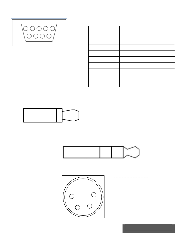
75
6. Connector and pin assignment
1) RS-422 D-Sub 9pin
2) GPI IN/OUT 3.5φ 2P mini plug/jack
3) Intercom 3.5φ 4P mini plug/jack (CTIA compliance)
4) DC Power Input ITT-Cannon XLR-4
Pin# RS‐422
1TXD‐
2TXD+
3RTS‐
4RTS+
5GND
6RXD‐
7RXD+
8CTS‐
9CTS+
1
5
6
9
GNDContact+
GND
MICLeft
Right
1
23
4
1 -
2 NC
3 NC
4 +

76
7. Index
3
3G-SDI ...................................................................................................... 68, 71
5
5GHz ..................................................................................................... 9, 68, 71
8
802.11n ..................................................................................................... 68, 71
A
A-4XANT .................................................................................................. 15, 21
Adaptive variable-rate control ........................................................................ 4
Adopter Plate ................................................................................................. 15
A-MT2V .......................................................................................................... 15
antenna ................................................................. 10, 15, 19, 20, 21, 43, 68, 71
audio ....................................................................................... 45, 55, 56, 62, 64
AUTO ............................................................................................ 51, 55, 59, 62
B
backlight ............................................................................................. 43, 69, 72
battery ............................................................................................................ 22
bit rate ........................................................................ 27, 51, 55, 59, 62, 69, 71
bps ................................................................................................. 41, 63, 69, 72
button ............................................................................................................. 26
C
cable ........................................................................ 7, 15, 21, 23, 38, 41, 44, 46
camera ...................................................................................................... 35, 37
Cannon ......................................................................................... 42, 69, 72, 74
CE ..................................................................................................................... 2
certification ...................................................................................................... 9
channel ..................................................................................................... 55, 62
Channel ................................................................ 28, 51, 52, 57, 59, 65, 68, 71

77
channel capacity ...................................................................................... 55, 62
coaxial ............................................................................................................. 44
codec ...................................................................... 44, 51, 54, 58, 59, 61, 62, 66
connect .................................................................................... 35, 37, 40, 56, 65
Connector ......................................................................... 36, 38, 41, 69, 72, 74
contact signal ........................................................................................... 38, 72
CTIA ................................................................................................... 69, 72, 74
cursor .................................................................................................. 11, 13, 26
CW-F25 ....................................................... 1, 10, 21, 29, 40, 46, 47, 49, 52, 82
D
DC ..................................................................................... 11, 14, 22, 70, 72, 74
default ................................................. 32, 36, 48, 50, 54, 56, 58, 61, 62, 64, 66
DFS ....................................................... 5, 30, 43, 51, 52, 53, 57, 65, 67, 68, 71
DHCP ................................................................................ 51, 53, 57, 59, 60, 65
Directional .......................................................................................... 15, 68, 71
disconnect ................................................................................................. 56, 65
display .......................................................................... 6, 27, 48, 50, 57, 65, 67
downlink video ....................................................... 4, 31, 44, 45, 55, 68, 71, 72
D-Sub ................................................................................ 12, 14, 41, 69, 72, 74
Dynamic Frequency Selection ......................................................................... 5
E
embedded audio ........................................................................... 51, 55, 59, 62
ENTER ............................................................................. 11, 13, 25, 26, 48, 49
ESC ......................................................................................... 11, 13, 26, 69, 72
Ethernet ................................................................................. 11, 14, 46, 69, 72
F
FCC ................................................................................................................... 2
firmware ........................................................................... 48, 49, 51, 58, 59, 66
frequency ............................................ 28, 30, 33, 35, 38, 41, 51, 52, 57, 59, 65
G
gain ..................................................................................................... 15, 56, 64
gateway......................................................................................... 51, 54, 59, 61
GPI ................................................ 11, 14, 37, 38, 39, 46, 55, 62, 63, 69, 72, 74

78
H
H.264 .................................................................... 45, 51, 54, 55, 62, 68, 69, 71
HD-SDI ..................................................................................................... 68, 71
Headset ........................................................................................................... 10
I
IDX .................................................................................... 1, 2, 22, 80, 81, 82, 1
IEEE ......................................................................................................... 68, 71
indoor ................................................................................................................ 9
intercom ........................................ 12, 13, 35, 36, 46, 51, 56, 59, 64, 69, 72, 74
interference ...................................................................................................... 2
IP ............................................. 26, 33, 46, 47, 51, 53, 54, 57, 59, 60, 61, 62, 65
IP address ..................................... 26, 46, 47, 51, 53, 54, 57, 59, 60, 61, 62, 65
IP camera ....................................................................................................... 33
J
jack ................................................................................................ 38, 69, 72, 74
L
LAN ........................................ 33, 40, 47, 52, 53, 54, 56, 60, 61, 62, 65, 69, 72
LCD ....................................................................... 11, 13, 24, 43, 48, 49, 69, 72
LED ..................................................................................................... 67, 69, 72
license ............................................................................................................... 9
link ...................................................................................................... 27, 51, 59
lithium-ion ...................................................................................................... 22
M
MAC ........................................................................................ 51, 53, 57, 59, 65
menu ......... 11, 13, 24, 26, 30, 32, 33, 35, 36, 38, 41, 46, 48, 49, 53, 57, 60, 65
mic .......................................................................................... 36, 51, 56, 59, 64
MIMO ................................................................................................. 15, 68, 71
monitor ......................................................................................... 30, 35, 37, 44
N
netmask ...................................................................... 44, 51, 54, 57, 59, 61, 65
network ....................................................................... 26, 51, 53, 54, 59, 60, 61

79
O
outdoor .............................................................................................................. 9
P
password ....................................................................................... 51, 52, 59, 60
phone ...................................................................................... 36, 51, 56, 59, 64
plug ....................................................................................................... 7, 21, 74
Power base station ......................................................................................... 22
power supply .......................................................... 7, 22, 23, 35, 37, 40, 42, 43
profile ................................................................................ 45, 51, 54, 55, 69, 71
push button .................................................................................................... 24
P-V2CL ............................................................................................... 15, 16, 18
R
reboot .......................................................................... 43, 48, 49, 51, 58, 59, 66
regulations ....................................................................................................... 9
remote ..................................... 38, 41, 44, 46, 51, 55, 59, 61, 62, 63, 64, 69, 72
Remote .................................... 38, 41, 44, 46, 51, 55, 59, 61, 62, 63, 64, 69, 72
return video .............................. 4, 31, 32, 34, 35, 37, 40, 44, 45, 59, 62, 69, 71
RP-SMA .............................................................................................. 11, 14, 21
RS-422 ................................................ 12, 14, 40, 41, 46, 59, 63, 64, 69, 72, 74
S
S/N ratio ......................................................................................................... 27
screw hole ................................................................................................. 12, 13
SDI ............................................................ 11, 14, 27, 44, 55, 62, 68, 69, 71, 72
setup ............... 11, 13, 26, 28, 32, 38, 41, 46, 48, 50, 51, 52, 53, 54, 59, 60, 61
signal strength ............................................................................................... 27
SMA .......................................................................................................... 68, 71
SNR ................................................................................................................. 27
SSID .................................................................................. 51, 52, 57, 59, 60, 65
status ...................................... 11, 13, 38, 42, 51, 56, 57, 59, 64, 65, 67, 69, 72
Status LED ................................................................. 11, 13, 42, 43, 67, 69, 72
switch ...................................................................................... 12, 13, 23, 69, 72
system ............................................................... 48, 49, 51, 58, 59, 66, 69, 72, 1

80
T
tally ........................................................................................................... 37, 46
Tally .................................................................................. 38, 46, 51, 55, 59, 62
transmission ................................................. 4, 5, 45, 55, 62, 63, 68, 69, 71, 72
U
USB ................................................................................... 12, 13, 48, 49, 69, 72
V
Vcc ................................................................................................................... 46
V-Mount .................................................................................................... 15, 16
V-Plate ................................................................................................ 13, 15, 16
W
WDS .................................................................................................... 51, 53, 57
wireless ............................... 5, 27, 28, 51, 52, 53, 56, 57, 59, 60, 64, 65, 68, 71
Wireless LAN ....................................................................................... 5, 52, 60
X
XLR-4 ................................................................................ 11, 14, 42, 69, 72, 74

81
VI. Warranty & Service
1. Product warranty
Warranty period of this product is 1 years after purchase.
Warranty covers manufacturing defects caused by poor workmanship or
materials.
Warranty may be voided even within the warranty period when IDX noticed
followings: Improper use of this product / Malfunction due to excess or
deficiency of power / Malfunction due to power short circuit / Physical
damages caused by dropping or vibration / Malfunction due to water /
Unauthorized used and/or modification done by customer
Original serial numbers removed or tampered with voids any warranty.
2. About exemptions
IDX does not take responsibility for failure generated by or as a result of any of the
following items.
Damage caused by natural disasters, such as earthquakes, thunder storms,
flood damage and fire or acts by third parties outside the responsibility of our
company other accidents, and intentional negligence and misuse by the user,
or use under unusual conditions.
Consequential damage through misuse of this product, or malfunction (change,
disappearance of the information contents, loss of profits, enterprise failure,
etc.)
Damage produced by non-compliance with the items mentioned in the
operating manual.
Damage produced from using non-compatible hardware and software does not
approved, tested by IDX .

82
3. Support & Service contact
When any assistance is needed, please contact your local IDX dealer or appropriate
IDX office below.
WEB
http://idxtek.com/idx_contact/form
Contact us
IDX System Technology, Inc.
19001 Harborgate Way, Suite 105
Torrance, CA 90501 USA
Tel: +1-310-328-2850
Fax: +1-310-328-8202
E-mail: idx.usa@idx.tv

83
CW-F25 Instruction manual, US version.
XXWK140187
1st DRAFT Edition, 1 Jun. 2014
IDX Company, Ltd.
6-28-11 Shukugawara,
Tama-ku, Kawasaki-shi, Kanagawa-ken,
214-0021 JAPAN

6
Ka
w
E
In Japan /
A
IDX Company
,
6
-28-11 Shuku
g
Tama-Ku
w
asaki-Shi, Kan
a
214-0021
JAPAN
TEL: 81-44-85
0
FAX: 81-44-85
0
E
-mail: idx.japa
n
FOR SA
L
A
sia
,
Ltd.
g
awara,
,
a
gawa-Ken
,
0
-8801
0
-8838
n
@idx.tv
http://ww
w
L
ES AND SE
In the Unit
e
IDX System Te
c
19001 Harb
o
Suite 105
T
CA 90
US
A
TEL: 1-310-
FAX: 1-310-
E-mail: idx.
u
w
.idx.tv/
RVICE CON
T
e
d States
c
hnology, Inc.
o
rgate Way,
T
orrance
501
A
328-2850
328-8202
u
sa@idx.tv
T
ACT
In Europe
IDX Techno
Unit 9,
L
Waterside
Berksh
EN
TEL: 44-
1
FAX: 44-
1
E-mail: id
x
/ Middle East.
logy Europe Ltd
.
L
angley Park,
Drive, Langley,
ire SL3 6AD
GLAND
1
753-547692
1
753-546660
x
.europe@idx.tv
.