IEI Integration 210UPC-V312 PANEL PC User Manual UPC V312 D525 Panel PC
IEI Integration Corp. PANEL PC UPC V312 D525 Panel PC
Contents
- 1. UPC-V312-D525_User Manual_Rev1_part1
- 2. UPC-V312-D525_User Manual_Rev1_part2
- 3. UPC-V312-D525_User Manual_Rev1_part3
UPC-V312-D525_User Manual_Rev1_part1
UPC-V312-D525 Panel PC
Page i
IEI Technology Corp.
User Manual
UPC-V312-D525 Panel PC
MODEL:
UPC-V312-D525
Panel PC with Touch Screen and Intel
®
Atom™ CPU,
GbE, Wireless, GPS, RFID, USB, Audio,
RS-232/422/485, RoHS Compliant, IP 65 Protection
Rev. 1.02 – 23 August, 2012
Click to buy NOW!
P
D
F
-
X
C
h
a
n
g
e
V
i
e
w
e
r
w
w
w
.
d
o
c
u
-
t
r
a
c
k
.
c
o
m
Click to buy NOW!
P
D
F
-
X
C
h
a
n
g
e
V
i
e
w
e
r
w
w
w
.
d
o
c
u
-
t
r
a
c
k
.
c
o
m
UPC-V312-D525 Panel PC
Page ii
Revision
Date Version
Changes
23 August, 2012 1.02 Replaced IEI MiniDOM support with mSATA support
8 December, 2011 1.01 Updated Table 1-4: System Specifications
Updated Section 2.2: Packing List
Updated Section 3.5: Mounting the System
23 September, 2011 1.00 Initial release
Click to buy NOW!
P
D
F
-
X
C
h
a
n
g
e
V
i
e
w
e
r
w
w
w
.
d
o
c
u
-
t
r
a
c
k
.
c
o
m
Click to buy NOW!
P
D
F
-
X
C
h
a
n
g
e
V
i
e
w
e
r
w
w
w
.
d
o
c
u
-
t
r
a
c
k
.
c
o
m

UPC-V312-D525 Panel PC
Page iii
Copyright
COPYRIGHT NOTICE
The information in this document is subject to change without prior notice in order to
improve reliability, design and function and does not represent a commitment on the part
of the manufacturer.
In no event will the manufacturer be liable for direct, indirect, special, incidental, or
consequential damages arising out of the use or inability to use the product or
documentation, even if advised of the possibility of such damages.
This document contains proprietary information protected by copyright. All rights are
reserved. No part of this manual may be reproduced by any mechanical, electronic, or
other means in any form without prior written permission of the manufacturer.
TRADEMARKS
All registered trademarks and product names mentioned herein are used for identification
purposes only and may be trademarks and/or registered trademarks of their respective
owners.
Click to buy NOW!
P
D
F
-
X
C
h
a
n
g
e
V
i
e
w
e
r
w
w
w
.
d
o
c
u
-
t
r
a
c
k
.
c
o
m
Click to buy NOW!
P
D
F
-
X
C
h
a
n
g
e
V
i
e
w
e
r
w
w
w
.
d
o
c
u
-
t
r
a
c
k
.
c
o
m

UPC-V312-D525 Panel PC
Page iv
WARNING
This device complies with Part 15 of the FCC Rules. Operation is subject to the following
two conditions:
(1) this device may not cause harmful interference, and(2) this device must accept any
interference received, including interference that may cause undesired operation.
NOTE: This equipment has been tested and found to comply with the limits for a Class
B digital device, pursuant to part 15 of the FCC Rules. These limits are designed to
provide reasonable protection against harmful interference in a residential installation.
This equipment generates, uses and can radiate radio frequency energy and, if not
installed and used in accordance with the instructions, may cause harmful interference
to radio communications.
However, there is no guarantee that interference will not occur in a particular
installation. If this equipment does cause harmful interference to radio or television
reception, which can be determined by turning the equipment off and on, the user is
encouraged to try to correct the interference by one or more of the following measures:
—Reorient or relocate the receiving antenna.
—Increase the separation between the equipment and receiver.
—Connect the equipment into an outlet on a circuit different from that to which the
receiver is connected.
—Consult the dealer or an experienced radio/ TV technician for help.
You are cautioned that any change or modifications to the equipment not expressly
approve by the party responsible for compliance could void your authority to operate
such equipment.
IMPORTANT NOTE:
FCC Radiation Exposure Statement:
This equipment complies with FCC radiation exposure limits set forth for an
uncontrolled environment. This equipment should be installed and operated with
minimum distance 20cm between the radiator & your body.
Click to buy NOW!
P
D
F
-
X
C
h
a
n
g
e
V
i
e
w
e
r
w
w
w
.
d
o
c
u
-
t
r
a
c
k
.
c
o
m
Click to buy NOW!
P
D
F
-
X
C
h
a
n
g
e
V
i
e
w
e
r
w
w
w
.
d
o
c
u
-
t
r
a
c
k
.
c
o
m

UPC-V312-D525 Panel PC
Page v
Table of Contents
1 INTRODUCTION.......................................................................................................... 1
1.1 OVERVIEW.................................................................................................................. 2
1.2 SYSTEM VARIATIONS.................................................................................................. 3
1.3 FEATURES................................................................................................................... 3
1.4 EXTERNAL OVERVIEW................................................................................................ 4
1.4.1 Front Panel ........................................................................................................ 4
1.4.1.1 LED Indicators............................................................................................ 5
1.4.2 Bottom Panel...................................................................................................... 7
1.4.3 Left Side Panel................................................................................................... 8
1.4.4 Right Side Panel................................................................................................. 9
1.4.5 Rear Panel ......................................................................................................... 9
1.4.6 Frame (Function Keys).................................................................................... 10
1.5 DIMENSIONS..............................................................................................................11
1.6 SPECIFICATIONS ....................................................................................................... 12
2 UNPACKING ............................................................................................................... 15
2.1 UNPACKING.............................................................................................................. 16
2.2 PACKING LIST........................................................................................................... 17
3 INSTALLATION ......................................................................................................... 19
3.1 ANTI-STATIC PRECAUTIONS...................................................................................... 20
3.2 INSTALLATION PRECAUTIONS ................................................................................... 20
3.3 PREINSTALLED COMPONENTS................................................................................... 21
3.4 CF CARD INSTALLATION .......................................................................................... 22
3.5 MOUNTING THE SYSTEM .......................................................................................... 23
3.5.1 Arm Mounting .................................................................................................. 25
3.5.2 Stand Mounting................................................................................................ 26
3.5.3 Wall Mounting.................................................................................................. 26
3.6 BOTTOM PANEL CONNECTORS ................................................................................. 29
3.6.1 External Peripheral Device Connection.......................................................... 29
Click to buy NOW!
P
D
F
-
X
C
h
a
n
g
e
V
i
e
w
e
r
w
w
w
.
d
o
c
u
-
t
r
a
c
k
.
c
o
m
Click to buy NOW!
P
D
F
-
X
C
h
a
n
g
e
V
i
e
w
e
r
w
w
w
.
d
o
c
u
-
t
r
a
c
k
.
c
o
m

UPC-V312-D525 Panel PC
Page vi
3.6.2 ACC Mode Selection........................................................................................ 32
3.6.3 AT/ATX Power Mode Selection........................................................................ 32
3.6.4 Audio Connectors............................................................................................. 33
3.6.5 CAN-bus Terminal Block.................................................................................. 33
3.6.6 LAN Connector ................................................................................................ 33
3.6.7 Power Input 1, 3-pin Terminal Block............................................................... 35
3.6.8 Power Input 2, DIN Connector........................................................................ 35
3.6.9 RJ-45 RS-232 Serial Port................................................................................. 35
3.6.10 RS-422/485 Serial Port.................................................................................. 37
3.6.11 USB Connectors............................................................................................. 38
3.6.12 VGA Connector.............................................................................................. 40
3.7 REDUNDANT POWER ................................................................................................ 42
3.7.1 ACC ON ........................................................................................................... 43
3.7.1.1 Boot-up ..................................................................................................... 43
3.7.1.2 Switch to Backup Power........................................................................... 44
3.7.1.3 Shutdown .................................................................................................. 44
3.7.2 ACC OFF......................................................................................................... 45
3.7.2.1 Boot-up ..................................................................................................... 45
3.7.2.2 Switch to Backup Power........................................................................... 46
3.7.2.3 Shutdown .................................................................................................. 47
3.8 REMOTE CONTROL................................................................................................... 48
4 AMI BIOS SETUP....................................................................................................... 49
4.1 INTRODUCTION......................................................................................................... 50
4.1.1 Starting Setup................................................................................................... 50
4.1.2 Using Setup...................................................................................................... 50
4.1.3 Getting Help..................................................................................................... 51
4.1.4 BIOS Menu Bar................................................................................................ 51
4.2 MAIN........................................................................................................................ 52
4.3 ADVANCED............................................................................................................... 53
4.3.1 ACPI Settings................................................................................................... 53
4.3.2 CPU Configuration.......................................................................................... 55
4.3.3 IDE Configuration ........................................................................................... 56
4.3.4 USB Configuration........................................................................................... 57
4.3.5 Super IO Configuration ................................................................................... 58
Click to buy NOW!
P
D
F
-
X
C
h
a
n
g
e
V
i
e
w
e
r
w
w
w
.
d
o
c
u
-
t
r
a
c
k
.
c
o
m
Click to buy NOW!
P
D
F
-
X
C
h
a
n
g
e
V
i
e
w
e
r
w
w
w
.
d
o
c
u
-
t
r
a
c
k
.
c
o
m
UPC-V312-D525 Panel PC
Page vii
4.3.5.1 Serial Port n Configuration....................................................................... 59
4.3.6 H/W Monitor.................................................................................................... 64
4.3.7 Serial Port Console Redirection ...................................................................... 65
4.3.7.1 Console Redirection Settings.................................................................... 66
4.3.8 IEI Feature....................................................................................................... 68
4.4 CHIPSET ................................................................................................................... 68
4.4.1 Host Bridge Configuration .............................................................................. 69
4.4.2 South Bridge Configuration............................................................................. 70
4.4.3 Intel IGD SWSCI OpRegion............................................................................. 72
4.5 BOOT........................................................................................................................ 74
4.6 SAV E & EXIT ............................................................................................................ 75
5 SOFTWARE DRIVERS .............................................................................................. 78
5.1 AVAILABLE SOFTWARE DRIVERS .............................................................................. 79
5.2 STARTING THE DRIVER PROGRAM ............................................................................ 79
5.3 CHIPSET DRIVER INSTALLATION............................................................................... 80
5.4 GRAPHICS DRIVER INSTALLATION............................................................................ 83
5.5 LAN DRIVER INSTALLATION.................................................................................... 87
5.6 AUDIO DRIVER INSTALLATION ................................................................................. 90
5.7 TOUCH SCREEN DRIVER INSTALLATION ................................................................... 92
5.7.1 Calibrating the Touch Screen........................................................................... 95
5.8 GPS DRIVER INSTALLATION..................................................................................... 97
5.9 CAN-BUS DRIVER INSTALLATION .......................................................................... 100
A BIOS CONFIGURATION OPTIONS..................................................................... 105
A.1 BIOS CONFIGURATION OPTIONS........................................................................... 106
B ONE KEY RECOVERY........................................................................................... 108
B.1 ONE KEY RECOVERY INTRODUCTION .................................................................... 109
B.1.1 System Requirement........................................................................................110
B.1.2 Supported Operating System..........................................................................111
B.2 SETUP PROCEDURE FOR WINDOWS.........................................................................112
B.2.1 Hardware and BIOS Setup .............................................................................113
B.2.2 Create Partitions ............................................................................................113
B.2.3 Install Operating System, Drivers and Applications......................................117
B.2.4 Building the Recovery Partition.....................................................................118
Click to buy NOW!
P
D
F
-
X
C
h
a
n
g
e
V
i
e
w
e
r
w
w
w
.
d
o
c
u
-
t
r
a
c
k
.
c
o
m
Click to buy NOW!
P
D
F
-
X
C
h
a
n
g
e
V
i
e
w
e
r
w
w
w
.
d
o
c
u
-
t
r
a
c
k
.
c
o
m

UPC-V312-D525 Panel PC
Page viii
B.2.5 Create Factory Default Image....................................................................... 120
B.3 AUTO RECOVERY SETUP PROCEDURE.................................................................... 125
B.4 SETUP PROCEDURE FOR LINUX.............................................................................. 129
B.5 RECOVERY TOOL FUNCTIONS ................................................................................ 133
B.5.1 Factory Restore ............................................................................................. 134
B.5.2 Backup System............................................................................................... 135
B.5.3 Restore Your Last Backup.............................................................................. 136
B.5.4 Manual........................................................................................................... 137
B.6 RESTORE SYSTEMS FROM A LINUX SERVER THROUGH LAN.................................. 138
B.6.1 Configure DHCP Server Settings.................................................................. 139
B.6.2 Configure TFTP Settings............................................................................... 140
B.6.3 Configure One Key Recovery Server Settings ............................................... 141
B.6.4 Start the DHCP, TFTP and HTTP ................................................................. 142
B.6.5 Create Shared Directory................................................................................ 142
B.6.6 Setup a Client System for Auto Recovery ...................................................... 143
B.7 OTHER INFORMATION ............................................................................................ 146
B.7.1 Using AHCI Mode or ALi M5283 / VIA VT6421A Controller....................... 146
B.7.2 System Memory Requirement ........................................................................ 148
C SAFETY PRECAUTIONS....................................................................................... 149
C.1 SAFETY PRECAUTIONS........................................................................................... 150
C.1.1 General Safety Precautions........................................................................... 150
C.1.2 Anti-static Precautions.................................................................................. 151
C.1.3 Product Disposal........................................................................................... 151
C.2 MAINTENANCE AND CLEANING PRECAUTIONS ...................................................... 152
C.2.1 Maintenance and Cleaning ........................................................................... 152
C.2.2 Cleaning Tools............................................................................................... 153
D WATCHDOG TIMER .............................................................................................. 154
E HAZARDOUS MATERIALS DISCLOSURE ....................................................... 157
E.1 HAZARDOUS MATERIAL DISCLOSURE TABLE FOR IPB PRODUCTS CERTIFIED AS
ROHS COMPLIANT UNDER 2002/95/EC WITHOUT MERCURY ..................................... 158
Click to buy NOW!
P
D
F
-
X
C
h
a
n
g
e
V
i
e
w
e
r
w
w
w
.
d
o
c
u
-
t
r
a
c
k
.
c
o
m
Click to buy NOW!
P
D
F
-
X
C
h
a
n
g
e
V
i
e
w
e
r
w
w
w
.
d
o
c
u
-
t
r
a
c
k
.
c
o
m

UPC-V312-D525 Panel PC
Page ix
List of Figures
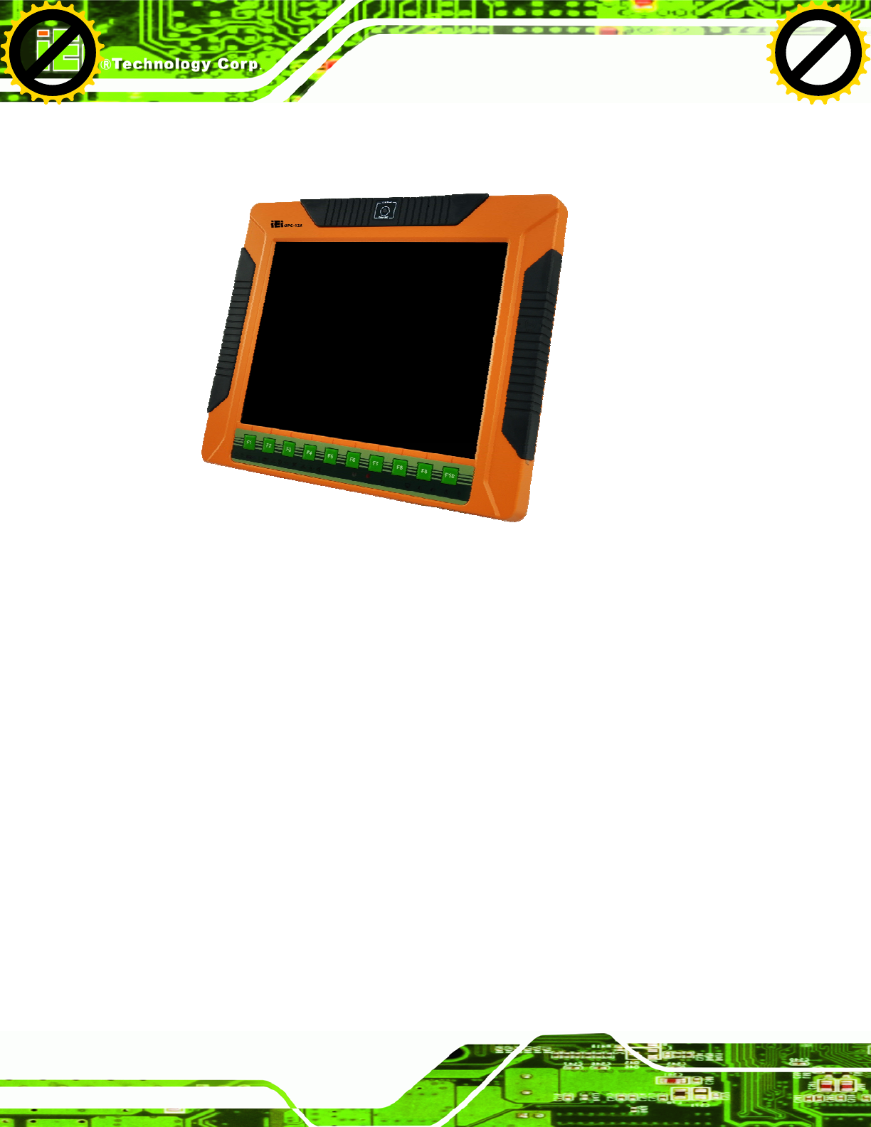
Figure 1-1: UPC-V312-D525 Panel PC...........................................................................................2
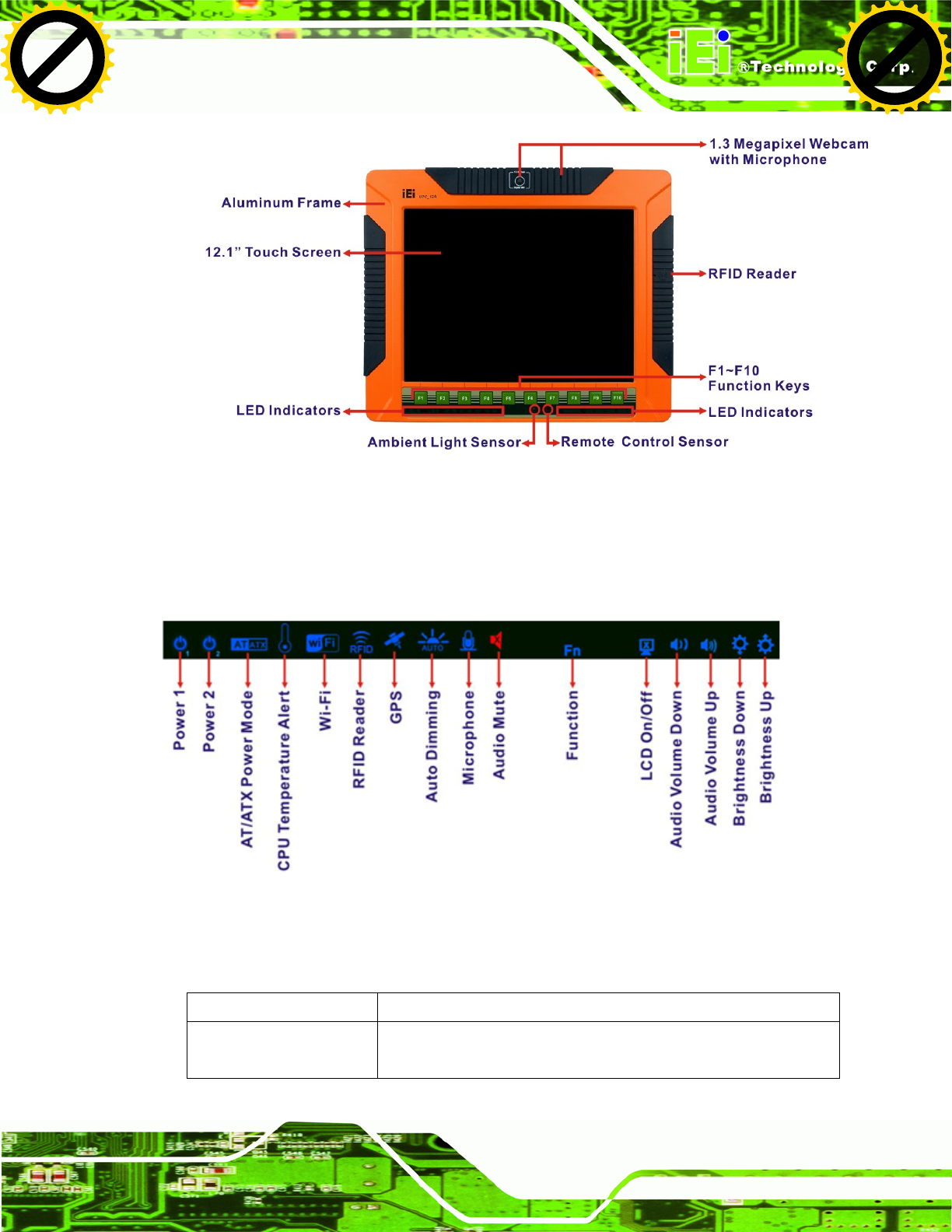
Figure 1-2: Front View....................................................................................................................5
Figure 1-3: LED Indicators.............................................................................................................5
Figure 1-4: Bottom View ................................................................................................................8
Figure 1-5: Left Side View..............................................................................................................8
Figure 1-6: Left Side View..............................................................................................................9
Figure 1-7: Rear View.....................................................................................................................9
Figure 1-8: Function Key Locations ...........................................................................................10
Figure 1-9: UPC-V312-D525 Dimensions (mm)..........................................................................11
Figure 3-1: Remove the CF Card Slot Panel ..............................................................................22
Figure 3-2: CF Card Installation ..................................................................................................23
Figure 3-7: VESA Mount Retention Screw Holes ......................................................................24
Figure 3-8: Mounting Brackets (Side Panels)............................................................................24
Figure 3-9: VESA Compliant Arm................................................................................................25
Figure 3-10: VESA Compliant Stand...........................................................................................26
Figure 3-11: Wall-mounting Bracket...........................................................................................27
Figure 3-12: Chassis Support Screws........................................................................................28
Figure 3-13: Secure the Panel PC ...............................................................................................29
Figure 3-14: I/O Cover Retention Screws...................................................................................30
Figure 3-15: External Peripheral Device Connection................................................................30
Figure 3-16: Rubber Gasket Removal.........................................................................................30
Figure 3-17: Rubber Gasket and Cable ......................................................................................31
Figure 3-18: Reinstall the I/O Cover............................................................................................31
Figure 3-19: External Peripheral Device Connection Complete ..............................................32
Figure 3-20: ACC Mode Switch ...................................................................................................32
Figure 3-21: AT/ATX Power Mode Switch ..................................................................................32
Figure 3-22: CAN-bus Terminal Block Pinouts..........................................................................33
Figure 3-23: RJ-45 Ethernet Connector......................................................................................33
Figure 3-24: LAN Connection......................................................................................................34
Figure 3-25: 3-pin Terminal Block Pinouts ................................................................................35
Figure 3-26: RJ-45 RS-232 Serial Port........................................................................................36
Click to buy NOW!
P
D
F
-
X
C
h
a
n
g
e
V
i
e
w
e
r
w
w
w
.
d
o
c
u
-
t
r
a
c
k
.
c
o
m
Click to buy NOW!
P
D
F
-
X
C
h
a
n
g
e
V
i
e
w
e
r
w
w
w
.
d
o
c
u
-
t
r
a
c
k
.
c
o
m

UPC-V312-D525 Panel PC
Page x
Figure 3-27: RJ-45 RS-232 Serial Device Connection...............................................................36
Figure 3-28: RS-422/485 Serial Port............................................................................................37
Figure 3-29: RS-422/485 Cable ....................................................................................................37
Figure 3-30: RS-422/485 Serial Port (DB-9)................................................................................38
Figure 3-31: USB Device Connection .........................................................................................39
Figure 3-32: VGA Connector .......................................................................................................40
Figure 3-33: VGA Connector .......................................................................................................41
Figure 3-34: Power Connectors ..................................................................................................42
Figure 3-35: ACC On: AT Mode...................................................................................................43
Figure 3-36: ACC On: ATX Mode.................................................................................................43
Figure 3-37: ACC On: Switch Between PWR1 and PWR2 ........................................................44
Figure 3-38: ACC On: Shutdown.................................................................................................45
Figure 3-39: ACC Off: AT Mode...................................................................................................46
Figure 3-40: ACC Off: ATX Mode ................................................................................................46
Figure 3-41: ACC Off: Switch Between PWR1 and PWR2........................................................46
Figure 3-42: ACC Off: Shutdown.................................................................................................47
Figure 3-43: Remote Control .......................................................................................................48
Figure 5-1: Chipset Driver Screen...............................................................................................80
Figure 5-2: Chipset Driver Welcome Screen..............................................................................81
Figure 5-3: Chipset Driver License Agreement .........................................................................81
Figure 5-4: Chipset Driver Read Me File ....................................................................................82
Figure 5-5: Chipset Driver Setup Operations ............................................................................82
Figure 5-6: Chipset Driver Installation Finish Screen...............................................................83
Figure 5-7: Graphics Driver Read Me File..................................................................................84
Figure 5-8: Graphics Driver Setup Files Extracted ...................................................................84
Figure 5-9: Graphics Driver Welcome Screen ...........................................................................85
Figure 5-10: Graphics Driver License Agreement.....................................................................85
Figure 5-11: Graphics Driver Read Me File................................................................................86
Figure 5-12: Graphics Driver Setup Operations........................................................................86
Figure 5-13: Graphics Driver Installation Finish Screen ..........................................................87
Figure 5-14: LAN Driver Welcome Screen .................................................................................88
Figure 5-15: LAN Driver Welcome Screen .................................................................................88
Figure 5-16: LAN Driver Installation ...........................................................................................89
Figure 5-17: LAN Driver Installation Complete..........................................................................89
Figure 5-18: Audio Driver Welcome Screen...............................................................................90
Click to buy NOW!
P
D
F
-
X
C
h
a
n
g
e
V
i
e
w
e
r
w
w
w
.
d
o
c
u
-
t
r
a
c
k
.
c
o
m
Click to buy NOW!
P
D
F
-
X
C
h
a
n
g
e
V
i
e
w
e
r
w
w
w
.
d
o
c
u
-
t
r
a
c
k
.
c
o
m

UPC-V312-D525 Panel PC
Page xi
Figure 5-19: Audio Driver Installation.........................................................................................91
Figure 5-20: AC’97 Driver Installation Complete.......................................................................91
Figure 5-21: Touch Screen Driver Welcome Screen.................................................................92
Figure 5-22: Touch Screen Driver License Agreement.............................................................93
Figure 5-23: Touch Screen Driver Choose Install Location.....................................................93
Figure 5-24: Touch Screen Driver Installation Screen..............................................................94
Figure 5-25: Touch Screen Driver Update Complete................................................................94
Figure 5-26: PenMount Monitor Icon..........................................................................................95
Figure 5-27: PenMount Monitor Popup Menu............................................................................95
Figure 5-28: Configuration Screen..............................................................................................96
Figure 5-29: Calibration Initiation Screen ..................................................................................96
Figure 5-30: Calibration Screen ..................................................................................................97
Figure 5-31: GPS Driver Welcome Screen .................................................................................98
Figure 5-32: GPS Driver Choose Install Location .....................................................................98
Figure 5-33: Installing GPS Driver ..............................................................................................99
Figure 5-34: GPS Driver Installation Complete..........................................................................99
Figure 5-35: Windows Control Panel....................................................................................... 100
Figure 5-36: System Icon.......................................................................................................... 101
Figure 5-37: Device Manager Tab ............................................................................................ 102
Figure 5-38: Search for Suitable Driver................................................................................... 103
Figure 5-39: Locate Driver Files............................................................................................... 103
Figure B-1: IEI One Key Recovery Tool Menu ........................................................................ 109
Figure B-2: Launching the Recovery Tool.............................................................................. 114
Figure B-3: Recovery Tool Setup Menu .................................................................................. 114
Figure B-4: Command Prompt ................................................................................................. 115
Figure B-5: Partition Creation Commands.............................................................................. 116
Figure B-6: Launching the Recovery Tool.............................................................................. 118
Figure B-7: Manual Recovery Environment for Windows ..................................................... 118
Figure B-8: Building the Recovery Partition........................................................................... 119
Figure B-9: Press Any Key to Continue .................................................................................. 119
Figure B-10: Press F3 to Boot into Recovery Mode............................................................... 120
Figure B-11: Recovery Tool Menu ........................................................................................... 120
Figure B-12: About Symantec Ghost Window........................................................................ 121
Figure B-13: Symantec Ghost Path ......................................................................................... 121
Figure B-14: Select a Local Source Drive ............................................................................... 122
Click to buy NOW!
P
D
F
-
X
C
h
a
n
g
e
V
i
e
w
e
r
w
w
w
.
d
o
c
u
-
t
r
a
c
k
.
c
o
m
Click to buy NOW!
P
D
F
-
X
C
h
a
n
g
e
V
i
e
w
e
r
w
w
w
.
d
o
c
u
-
t
r
a
c
k
.
c
o
m

UPC-V312-D525 Panel PC
Page xii
Figure B-15: Select a Source Partition from Basic Drive ...................................................... 122
Figure B-16: File Name to Copy Image to ............................................................................... 123
Figure B-17: Compress Image.................................................................................................. 123
Figure B-18: Image Creation Confirmation............................................................................. 124
Figure B-19: Image Creation Complete................................................................................... 124
Figure B-20: Image Creation Complete................................................................................... 124
Figure B-21: Press Any Key to Continue ................................................................................ 125
Figure B-22: Auto Recovery Utility .......................................................................................... 126
Figure B-23: Launching the Recovery Tool............................................................................ 126
Figure B-24: Auto Recovery Environment for Windows ....................................................... 126
Figure B-25: Building the Auto Recovery Partition................................................................ 127
Figure B-26: Factory Default Image Confirmation ................................................................. 127
Figure B-27: Image Creation Complete................................................................................... 128
Figure B-28: Press any key to continue .................................................................................. 128
Figure B-29: Partitions for Linux.............................................................................................. 130
Figure B-30: Manual Recovery Environment for Linux ......................................................... 131
Figure B-31: Access menu.lst in Linux (Text Mode).............................................................. 132
Figure B-32: Recovery Tool Menu ........................................................................................... 132
Figure B-33: Recovery Tool Main Menu.................................................................................. 133
Figure B-34: Restore Factory Default...................................................................................... 134
Figure B-35: Recovery Complete Window .............................................................................. 135
Figure B-36: Backup System.................................................................................................... 135
Figure B-37: System Backup Complete Window ................................................................... 136
Figure B-38: Restore Backup ................................................................................................... 136
Figure B-39: Restore System Backup Complete Window..................................................... 137
Figure B-40: Symantec Ghost Window ................................................................................... 137
Click to buy NOW!
P
D
F
-
X
C
h
a
n
g
e
V
i
e
w
e
r
w
w
w
.
d
o
c
u
-
t
r
a
c
k
.
c
o
m
Click to buy NOW!
P
D
F
-
X
C
h
a
n
g
e
V
i
e
w
e
r
w
w
w
.
d
o
c
u
-
t
r
a
c
k
.
c
o
m
UPC-V312-D525 Panel PC
Page xiii
List of Tables
Table 1-1: System Variations.........................................................................................................3
Table 1-2: LED Indicators ..............................................................................................................6
Table 1-3: Function Keys.............................................................................................................10
Table 1-4: System Specifications................................................................................................14
Table 3-1: LAN Pinouts ................................................................................................................33
Table 3-2: RJ-45 Ethernet Connector LEDs...............................................................................34
Table 3-3: RJ-45 RS-232 Serial Port Pinouts .............................................................................36
Table 3-4: RS-422/485 Serial Port Pinouts .................................................................................37
Table 3-5: RS-422/485 Serial Port Pinouts .................................................................................38
Table 3-6: USB Port Pinouts........................................................................................................39
Table 3-7: VGA Connector Pinouts.............................................................................................40
Table 4-1: BIOS Navigation Keys................................................................................................51
Click to buy NOW!
P
D
F
-
X
C
h
a
n
g
e
V
i
e
w
e
r
w
w
w
.
d
o
c
u
-
t
r
a
c
k
.
c
o
m
Click to buy NOW!
P
D
F
-
X
C
h
a
n
g
e
V
i
e
w
e
r
w
w
w
.
d
o
c
u
-
t
r
a
c
k
.
c
o
m

UPC-V312-D525 Panel PC
Page 2
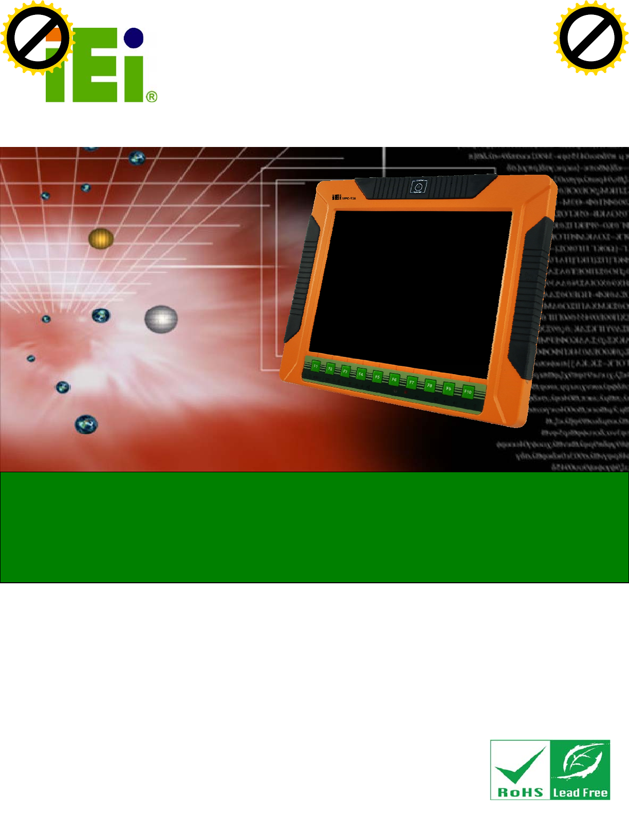
1.1 Overview
Figure 1-1: UPC-V312-D525 Panel PC
The fanless UPC-V312-D525 is Intel® Atom D525 powered panel PC with a rich variety
of functions and peripherals. The UPC-V312-D525 panel PC is designed for easy and
simplified integration into various vehicle applications.
An Intel® ICH8M chipset ensures optimal memory, graphics, and peripheral I/O support.
The system comes with 1GB of preinstalled DDR3 SDRAM ensuring smooth data
throughputs with reduced bottlenecks and fast system access.
The redundant dual DC power input of the UPC-V312-D525 increases the reliability of the
system and prevents data loss and system corruption from sudden power failure.
The CAN-bus interface allows the UPC-V312-D525 to communication with vehicles. Two
serial ports and five external USB 2.0 ports ensure simplified connectivity to a variety of
external peripheral devices. A VGA connector enables connectivity to other monitors for
dual display. Wi-Fi capabilities and the RJ-45 GbE connector ensure smooth connection
of the system to an external LAN.
Click to buy NOW!
P
D
F
-
X
C
h
a
n
g
e
V
i
e
w
e
r
w
w
w
.
d
o
c
u
-
t
r
a
c
k
.
c
o
m
Click to buy NOW!
P
D
F
-
X
C
h
a
n
g
e
V
i
e
w
e
r
w
w
w
.
d
o
c
u
-
t
r
a
c
k
.
c
o
m

UPC-V312-D525 Panel PC
Page 3
1.2 System Variations
The part numbers and system variations are listed below.
Part Numbers CPU RFID Reader
UPC-V312-D525/R/1G-R10 Intel® Atom D525 N/A
UPC-V312-D525/R-EM/1G-R10 Intel® Atom D525 EM card reader
UPC-V312-D525/R-MF/1G-R10 Intel® Atom D525 Mifare card reader
Table 1-1: System Variations
1.3 Features
The UPC-V312-D525 series features the following:
12.1'' 600nits 1024 x 768 LCD with LED backlight
Fanless system with 1.8GHz Intel® Atom™ D525 dual-core processor
Redundant dual DC input power
Dual-band 2.4/5GHz Wi-Fi 802.11 a/b/g/n
Reserved space for 3.75G / HSUPA USB module
Built-in 1.3 megapixel webcam with AF, AE and AWB capabilities
CAN-bus interface
Optional RFID reader for EM or Mifare cards
Optional GPS receiver
Provide two PCIe Mini card slots
F1 ~ F10 function keys and friendly indicators
IP 65 compliant system
AT or ATX power mode
Touch screen
RoHS comlpliance
Click to buy NOW!
P
D
F
-
X
C
h
a
n
g
e
V
i
e
w
e
r
w
w
w
.
d
o
c
u
-
t
r
a
c
k
.
c
o
m
Click to buy NOW!
P
D
F
-
X
C
h
a
n
g
e
V
i
e
w
e
r
w
w
w
.
d
o
c
u
-
t
r
a
c
k
.
c
o
m

UPC-V312-D525 Panel PC
Page 4
1.4 External Overview
The panel PC is a rectangular cubic structure that comprises of a screen, rear panel, top
panel, bottom panel and two side panels (left and right). An aluminum frame surrounds the
front screen. The rear panel provides screw holes for a wall-mounting bracket, and an arm
mounting interface. The bottom panel provides access to external interface connectors.
1.4.1 Front Panel
The front side of the UPC-V312-D525 is a flat panel TFT LCD screen surrounded by an
aluminum frame. At the top of the front panel features one 1.3 megapixel webcam that
supports auto-focus (AF), auto-exposure (AE) and auto white balance (AWB). The front
panel also has following buttons, LED indicators and sensors:
Buttons: F1~F10 (same as the function key on the keyboard)
LEDs
o Power 1 LED
o Power 2 LED
o AT/ATX power mode LED
o CPU temperature alert LED
o Wi-Fi connection LED
o RFID LED
o GPS LED
o Auto dimming LED
o Microphone on/off LED
o Audio mute LED
Sensors
o Ambient light sensor
o Infrared remote control sensor
Click to buy NOW!
P
D
F
-
X
C
h
a
n
g
e
V
i
e
w
e
r
w
w
w
.
d
o
c
u
-
t
r
a
c
k
.
c
o
m
Click to buy NOW!
P
D
F
-
X
C
h
a
n
g
e
V
i
e
w
e
r
w
w
w
.
d
o
c
u
-
t
r
a
c
k
.
c
o
m
UPC-V312-D525 Panel PC
Page 5
Figure 1-2: Front View
1.4.1.1 LED Indicators
The LED indicators on the front panel of the UPC-V312-D525 are shown below.
Figure 1-3: LED Indicators
The descriptions of each LED indicator are listed below.
LED Indicator Description
Power 1 Pulsing Orange: Power 1 is the main power and is in standby mode
Solid Orange: Power 1 is the second power and is in standby mode
Click to buy NOW!
P
D
F
-
X
C
h
a
n
g
e
V
i
e
w
e
r
w
w
w
.
d
o
c
u
-
t
r
a
c
k
.
c
o
m
Click to buy NOW!
P
D
F
-
X
C
h
a
n
g
e
V
i
e
w
e
r
w
w
w
.
d
o
c
u
-
t
r
a
c
k
.
c
o
m
UPC-V312-D525 Panel PC
Page 6
Solid Blue: Power 1 is providing power to the system
Power 2 Pulsing Orange: Power 2 is the main power and is in standby mode
Solid Orange: Power 2 is the second power and is in standby mode
Solid Blue: Power 2 is providing power to the system
AT/ATX Power Mode Shows the power mode status. Controlled by the AT/ATX power mode
switch.
CPU Temperature Alert Blue: the CPU temperature is normal.
Red: the CPU temperature is too high.
Wi-Fi The Wi-Fi module is enabled or disabled. Controlled by the BIOS (see
Section 4.4.2).
RFID Reader The optional RFID reader is enabled or disabled.
Controlled by the hot keys (see Section 1.4.6).
GPS The GPS receiver is enabled or disabled.
Controlled by the BIOS (see Section 4.4.2).
Auto Dimming The auto dimming function is enabled or disabled. Controlled by the
remote control (see Section 3.8).
Microphone The microphone is enabled or disabled. Controlled by the BIOS
(Section 4.4.2).
Audio Mute Light on when the audio is turned off.
Controlled by the hot keys (see Section 1.4.6).
Function
LCD on/off
Volume Down
Volume Up
Brightness Down
Brightness Up
Shows the status of the function key below the LED indicator. Blinks
when the corresponding button is pushed.
Table 1-2: LED Indicators
Click to buy NOW!
P
D
F
-
X
C
h
a
n
g
e
V
i
e
w
e
r
w
w
w
.
d
o
c
u
-
t
r
a
c
k
.
c
o
m
Click to buy NOW!
P
D
F
-
X
C
h
a
n
g
e
V
i
e
w
e
r
w
w
w
.
d
o
c
u
-
t
r
a
c
k
.
c
o
m

UPC-V312-D525 Panel PC
Page 7
CAUTION:
If the CPU temperature alert LED shows in red, the user must lower the
environment temperature or close some running applications to cool
down the CPU.
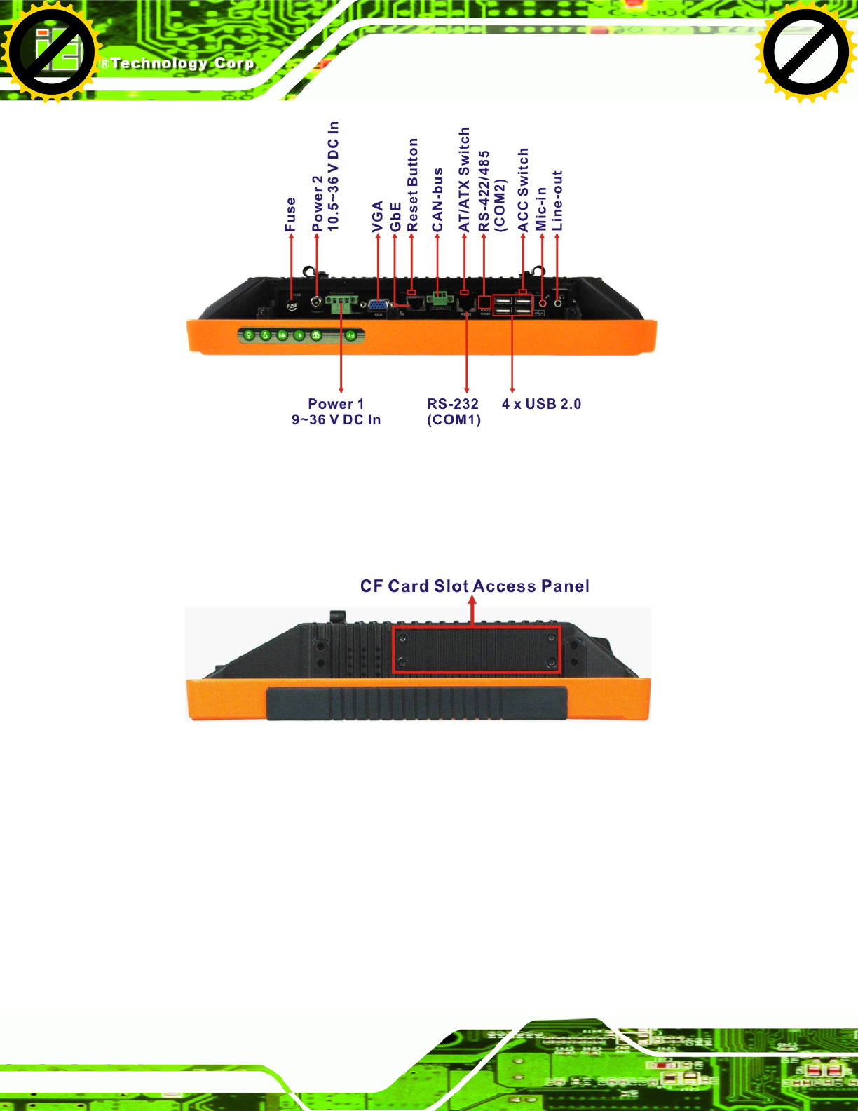
1.4.2 Bottom Panel
The following is a list of the bottom panel peripheral device connectors on the
UPC-V312-D525.
1 x 9 V ~ 36 V DC power input terminal block (Power 1)
1 x 10.5 V ~ 36 V DC power input connector (Power 2)
2 x Audio jacks
1 x CAN but connector
1 x RJ-45 GbE connector
1 x RS-232 COM port by RJ-45 connector
1 x RS-422/485 serial port (COM2) connector
4 x USB 2.0 connectors
1 x VGA connector
The bottom panel also includes the following switches and buttons:
1 x ACC on/off switch
1 x AT/ATX power mode switch
1 x Reset button
Click to buy NOW!
P
D
F
-
X
C
h
a
n
g
e
V
i
e
w
e
r
w
w
w
.
d
o
c
u
-
t
r
a
c
k
.
c
o
m
Click to buy NOW!
P
D
F
-
X
C
h
a
n
g
e
V
i
e
w
e
r
w
w
w
.
d
o
c
u
-
t
r
a
c
k
.
c
o
m