IEI Integration NAS-101RW Network Attatched Storage User Manual
IEI Integration Corp. Network Attatched Storage Users Manual
Users Manual

Disk ON-Line Server
ICP Electronics Inc.
NAS-104R.NAS-2108R.NAS-2108RW.NAS-101R.NAS-101RW
User’s Manual
FCC ID:RFHNAS-101RW (Only for NAS-101RW)
1
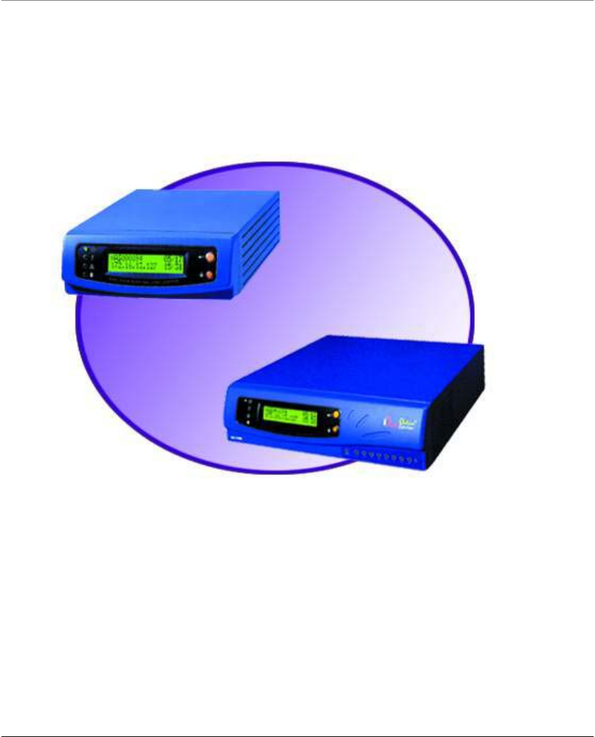
BROADBAND NETWORK ATTACHED STORAGE
Disk On-line Server
User’s Manual
Copyright 2000-2002, All Rights Reserved.
This manual applies to 2.12 or later versions of the Disk On-line Server
2002/06/06

2
CUSTOMER SERVICE
To obtain service or technical support for your system, please refer to the registration card for detailed
contacts.
TRADEMARKS
Disk On-line Server TM and IEI® are trademarks of ICP Electronics Inc.
Microsoft®, Windows® and Internet Explorer® are registered trademarks of Microsoft Inc. Novell® and
NetWare® are registered trademarks of Novell Inc. Apple® and Macintosh® are registered trademarks of
Apple Computer Inc. All other brand or product names are trademarks of their respective companies or
organizations.
LIMITED WARRANTY
In no event shall IEI’s liability exceed the price paid for the product from direct, indirect, special,
incidental, or consequential software, or its documentation. IEI offers no refunds for its products. IEI
makes no warranty or representation, expressed, implied, or statutory, with respect to its products or the
contents or use of this documentation and all accompanying software, and specifically disclaims its
quality, performance, merchantability, or fitness for any particular purpose. IEI reserves the right to revise
or update its products, software, or documentation without obligation to notify any individual or entity.
FCC STATEMENT
The IEI Disk On-line Server has been tested and found to comply with the limits for a Class B digital
device, pursuant to Part 15 of the FCC Rules. These limits are designed to provide reasonable protection.
This equipment generates, uses and can radiated radio frequency energy and, if not installed and used in
accordance with the instructions, may cause harmful interference to radio communications. However,
there is no guarantee that interference will not occur in a particular installation If this equipment does
cause harmful interference to radio or television reception, which can be determined by turning the
equipment off and on, the user is encouraged to try to correct the interference by one or more of the
following measures:
-Reorient or relocate the receiving antenna.
-Increase the separation between the equipment and receiver.
-Connect the equipment into an outlet on a circuit different from that to which the receiver is
connected.
-Consult the dealer or an experienced radio/TV technician for help.
Shielded interface cables must be used in order to comply with emission limits.
Changes or modifications not expressly approved by the party responsible for compliance could void the
user‘s authority to operate the equipment.
This equipment complies with FCC radiation exposure limits set forth for an uncontrolled environment.
In order to avoid the possibility of exceeding the FCC radio frequency exposure limits, human proximity
to the antenna shall not be less than 20cm (8 inches) during normal operation.
CAUTION
Danger of explosion if battery is incorrectly replaced. replace only with the same or equivalent type
recommended by the manufacturer. dispose of used batteries according to the manufacture's instruction.

3
Contents
O
Ov
ve
er
rv
vi
ie
ew
w
o
of
f
t
th
he
e
D
Di
is
sk
k
O
On
n-
-l
li
in
ne
e
S
Se
er
rv
ve
er
r.
..
..
..
..
..
..
..
..
..
..
..
..
..
..
..
..
..
..
..
..
..
..
..
..
..
..
..
..
..
..
..
..
..
..
..
..
..
..
..
..
..
..
..
..
..
..
..
..
..
..
..
..
..
..
..
..
..
..
..
..
..
..
..
..
..
..
..
..
..
..
..
..
..
..
..
..
..
..
..
..
..
..
..
..
..
..
..
..
..
..
..
..
..
..
..
..
..
..
..
..
..
..
..
.5
5
Introduction ...............................................................................................................................................5
Package Contents ......................................................................................................................................5
System Overview ......................................................................................................................................6
I
In
ns
st
ta
al
ll
la
at
ti
io
on
n
o
of
f
t
th
he
e
D
Di
is
sk
k
O
On
n-
-l
li
in
ne
e
S
Se
er
rv
ve
er
r.
..
..
..
..
..
..
..
..
..
..
..
..
..
..
..
..
..
..
..
..
..
..
..
..
..
..
..
..
..
..
..
..
..
..
..
..
..
..
..
..
..
..
..
..
..
..
..
..
..
..
..
..
..
..
..
..
..
..
..
..
..
..
..
..
..
..
..
..
..
..
..
..
..
..
..
..
..
..
..
..
..
..
..
..
..
..
..
..
..
..
..
..
..
..
..
..
..
..
.1
16
6
Installing the Hardware ...........................................................................................................................16
Set-up Before First Operation .................................................................................................................19
A
Ad
dm
mi
in
ni
is
st
tr
ra
at
ti
io
on
n
o
of
f
t
th
he
e
D
Di
is
sk
k
O
On
n-
-l
li
in
ne
e
S
Se
er
rv
ve
er
r.
..
..
..
..
..
..
..
..
..
..
..
..
..
..
..
..
..
..
..
..
..
..
..
..
..
..
..
..
..
..
..
..
..
..
..
..
..
..
..
..
..
..
..
..
..
..
..
..
..
..
..
..
..
..
..
..
..
..
..
..
..
..
..
..
..
..
..
..
..
..
..
..
..
..
..
..
..
..
..
..
..
..
..
..
..
..
..
..
..
..
..
..
.2
22
2
Accessing the Administration Page.........................................................................................................22
Server Administration .............................................................................................................................23
Quick Configuration................................................................................................................................25
System Settings .......................................................................................................................................25
Network Settings.....................................................................................................................................26
Disk Configuration..................................................................................................................................31
User Management....................................................................................................................................32
Network Share Management ...................................................................................................................34
System Tools...........................................................................................................................................36
Statistics & Logs .....................................................................................................................................37
A
Ac
cc
ce
es
ss
si
in
ng
g
t
th
he
e
D
Di
is
sk
k
O
On
n-
-l
li
in
ne
e
S
Se
er
rv
ve
er
r.
..
..
..
..
..
..
..
..
..
..
..
..
..
..
..
..
..
..
..
..
..
..
..
..
..
..
..
..
..
..
..
..
..
..
..
..
..
..
..
..
..
..
..
..
..
..
..
..
..
..
..
..
..
..
..
..
..
..
..
..
..
..
..
..
..
..
..
..
..
..
..
..
..
..
..
..
..
..
..
..
..
..
..
..
..
..
..
..
..
..
..
..
..
..
..
..
..
..
..
..
..
..
..
..
..
.3
38
8
Using Microsoft Windows ......................................................................................................................38
Using the Apple Mac Operating System .................................................................................................39
Using the Unix/Linux Operating System ................................................................................................45
Using Novell NetWare ............................................................................................................................45
Using a Web Browser..............................................................................................................................45
Using File Transfer Protocol (FTP).........................................................................................................45
I
In
ns
st
ta
al
ll
li
in
ng
g
t
th
he
e
N
Ne
et
tw
wo
or
rk
k
P
Pr
ri
in
nt
te
er
r
(
(F
Fo
or
r
N
NA
AS
S-
-2
21
10
08
8R
R/
/N
NA
AS
S-
-2
21
10
08
8R
RW
W
O
On
nl
ly
y)
).
..
..
..
..
..
..
..
..
..
..
..
..
..
..
..
..
..
..
..
..
..
..
..
..
..
..
..
..
..
..
..
..
..
..
..
..
..
..
..
..
..
..
..
..
..
.4
46
6
Enabling Network Printer Service...........................................................................................................46
Setting Up the Printer on Your Computer...............................................................................................47
D
Di
is
sk
k
O
On
n-
-l
li
in
ne
e
S
Se
er
rv
ve
er
r
-
-
M
Ma
ai
in
nt
te
en
na
an
nc
ce
e.
..
..
..
..
..
..
..
..
..
..
..
..
..
..
..
..
..
..
..
..
..
..
..
..
..
..
..
..
..
..
..
..
..
..
..
..
..
..
..
..
..
..
..
..
..
..
..
..
..
..
..
..
..
..
..
..
..
..
..
..
..
..
..
..
..
..
..
..
..
..
..
..
..
..
..
..
..
..
..
..
..
..
..
..
..
..
..
..
..
..
..
..
..
..
..
..
..
..
..
..
..
..
..
..
.5
51
1
Shutdown/Restart the Server...................................................................................................................51
Reset the Administrator Password & Network Settings..........................................................................51
Disk Failure or Malfunction....................................................................................................................52
Power Outage or Abnormal Shutdown....................................................................................................52
A
Ap
pp
pe
en
nd
di
ix
x
A
A
L
LC
CD
D
P
Pa
an
ne
el
l.
..
..
..
..
..
..
..
..
..
..
..
..
..
..
..
..
..
..
..
..
..
..
..
..
..
..
..
..
..
..
..
..
..
..
..
..
..
..
..
..
..
..
..
..
..
..
..
..
..
..
..
..
..
..
..
..
..
..
..
..
..
..
..
..
..
..
..
..
..
..
..
..
..
..
..
..
..
..
..
..
..
..
..
..
..
..
..
..
..
..
..
..
..
..
..
..
..
..
..
..
..
..
..
..
..
..
..
..
..
..
..
..
..
..
..
..
..
..
..
..
..
.5
53
3
Displayed Information.............................................................................................................................53
Checking IP Address, System and Disk Information ..............................................................................53

4
System Setup Function............................................................................................................................54
A
Ap
pp
pe
en
nd
di
ix
x
B
B
W
We
eb
b
F
Fi
il
le
e
M
Ma
an
na
ag
ge
er
r.
..
..
..
..
..
..
..
..
..
..
..
..
..
..
..
..
..
..
..
..
..
..
..
..
..
..
..
..
..
..
..
..
..
..
..
..
..
..
..
..
..
..
..
..
..
..
..
..
..
..
..
..
..
..
..
..
..
..
..
..
..
..
..
..
..
..
..
..
..
..
..
..
..
..
..
..
..
..
..
..
..
..
..
..
..
..
..
..
..
..
..
..
..
..
..
..
..
..
..
..
..
..
..
..
..
..
..
..
.5
55
5
Using Web File Manager.........................................................................................................................55
Web File Manager Icon...........................................................................................................................57
A
Ap
pp
pe
en
nd
di
ix
x
C
C
Q
Qu
ui
ic
ck
k
I
In
ns
st
ta
al
ll
l
W
Wi
iz
za
ar
rd
d.
..
..
..
..
..
..
..
..
..
..
..
..
..
..
..
..
..
..
..
..
..
..
..
..
..
..
..
..
..
..
..
..
..
..
..
..
..
..
..
..
..
..
..
..
..
..
..
..
..
..
..
..
..
..
..
..
..
..
..
..
..
..
..
..
..
..
..
..
..
..
..
..
..
..
..
..
..
..
..
..
..
..
..
..
..
..
..
..
..
..
..
..
..
..
..
..
..
..
..
..
..
..
..
..
.5
58
8
Introduction .............................................................................................................................................58
Screenshot ...............................................................................................................................................58
Operation Help ........................................................................................................................................59
A
Ap
pp
pe
en
nd
di
ix
x
D
D
R
Re
eg
gi
is
st
te
er
ri
in
ng
g
a
a
D
Dy
yn
na
am
mi
ic
c
D
Do
om
ma
ai
in
n
N
Na
am
me
e.
..
..
..
..
..
..
..
..
..
..
..
..
..
..
..
..
..
..
..
..
..
..
..
..
..
..
..
..
..
..
..
..
..
..
..
..
..
..
..
..
..
..
..
..
..
..
..
..
..
..
..
..
..
..
..
..
..
..
..
..
..
..
..
..
..
..
..
..
..
..
..
..
..
..
..
..
..
.6
61
1
Introduction .............................................................................................................................................61
Registration Procedure ............................................................................................................................61

5
Overview of the Disk On-line Server
Introduction
Thank you for choosing the Disk On-line Server. This product offers the following
features:
• Share your storage over Microsoft, Unix and Apple network.
• Protect your data via RAID technology and management.
• Easy administration through simple web interface.
• Built-in firewall / NAT router function for Internet sharing.
Package Contents
The Disk On-line Server™ box contains:
• Disk On-line Server
• User’s Manual
• Power Cord
• One CAT 5 Network Cable
• Quick Install Wizard CD-ROM or Floppy Diskette
• Warranty Registration Card
Chapter
1
6
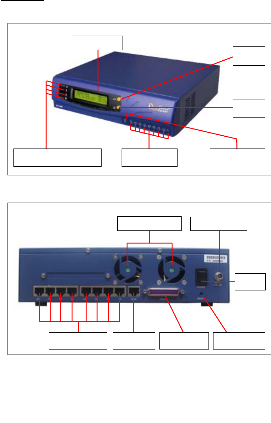
LED Indicators for
LAN Ports LED Indicator
for WAN Port
Setting
Switch
Setting
Switch A
LCD Panel
4 LED Indicators: Power, Error,
N
etwork, and Disk Access
System Overview
NAS-2108R
• Front View
• Front View
LAN Connectors WAN
Connector
Dual Ventilation Fans Power Connection
Output Connector
for Printer
Power
Switch
Configuration Reset
Switch
7
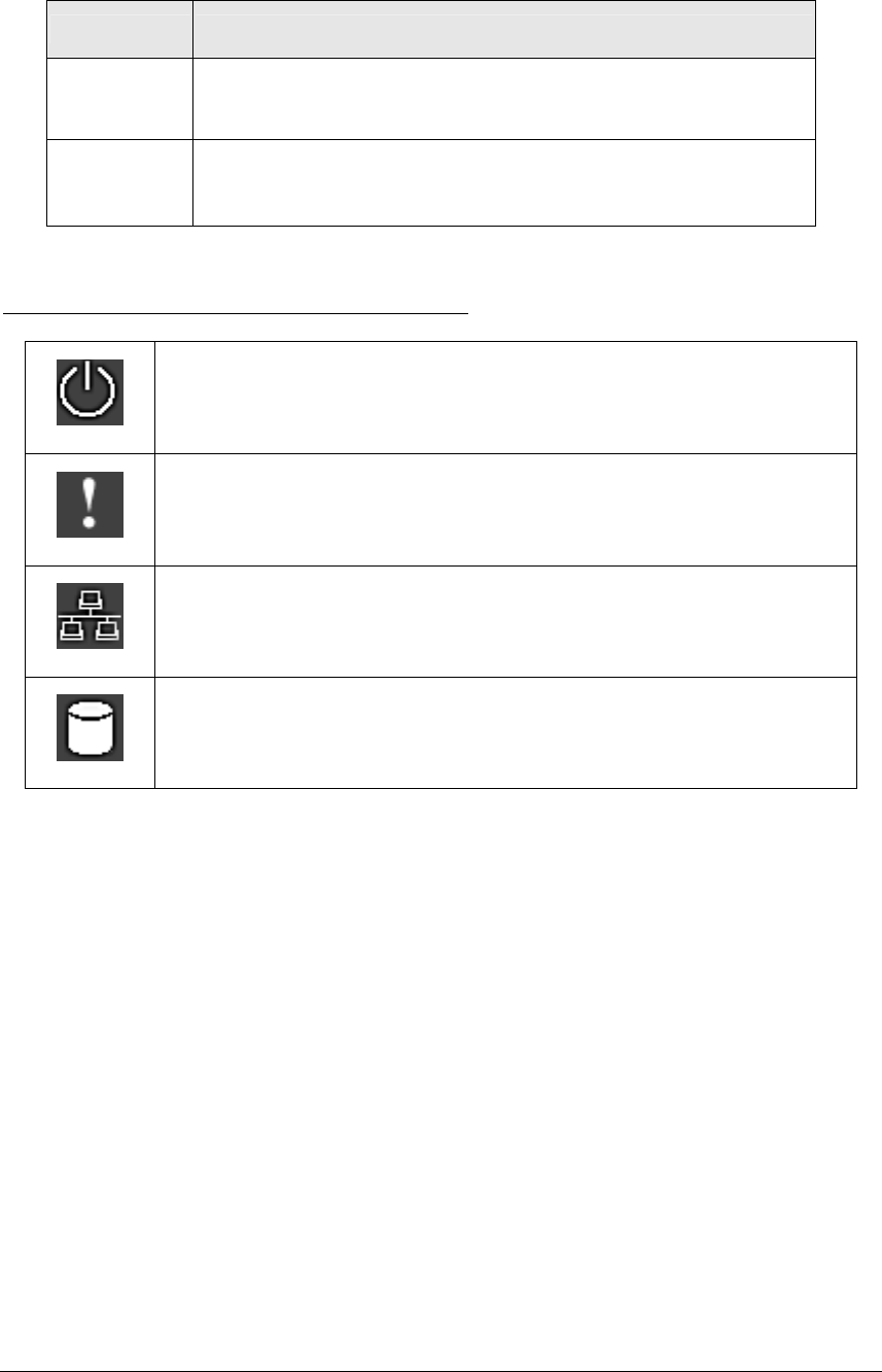
• Network Status Indicators
There are nine LED indicators at the lower right area of the rear panel. Each LED indicates
the network status of the corresponding WAN or LAN port as below:
Color Indicates
Green Current connection is at 100Mbps. The flashing light
indicates data is being transmitted.
Red Current connection is at 10Mbps. The flashing light
indicates data is being transmitted.
Indicator light at the left of the LCD panel
Shines when power is on
Indicates a system error which needs to be corrected
This light flashes when data is being transmitted through the
network
This light flashes when data is being stored or retrieved from the
disks
8
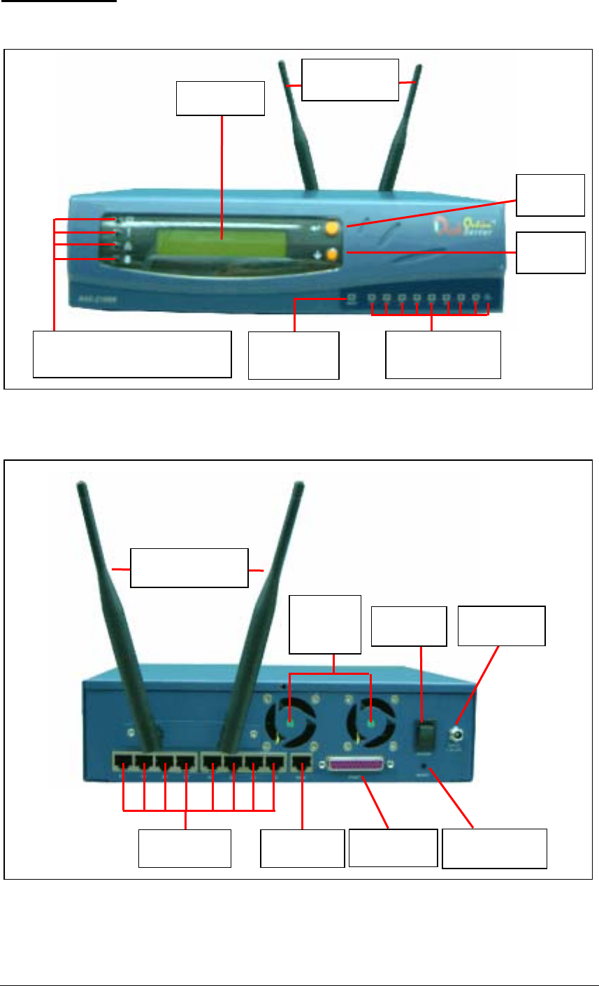
NAS-2108RW
Front View
• Rear View
Dual
Ventilation
Fans
Power
Connection
Power
Switch
LAN
Connectors WAN
Connector Output
Connector for Configuration
Reset Switch
Wireless LAN
Antenna
LED Indicator
for WAN Port
Setting
Switch B
Setting
Switch A
LCD Panel
4 LED Indicators: Power, Error,
N
etwork, and Disk Access LED Indicators for
LAN Ports
Wireless LAN
Antenna
9
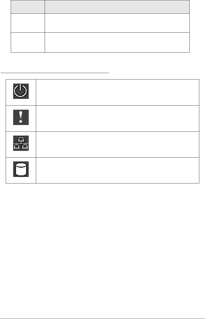
• Network Status Indicators
There are nine LED indicators at the lower right area of the rear panel. Each LED indicates
the network status of the corresponding WAN or LAN port as below:
Color Indicates
Green Current connection is at 100Mbps. The flashing light
indicates data is being transmitted.
Red Current connection is at 10Mbps. The flashing light
indicates data is being transmitted.
Indicator light at the left of the LCD panel
Shines when power is on
Indicates a system error which needs to be corrected
This light flashes when data is being transmitted through the
network
This light flashes when data is being stored or retrieved from the
disks
10
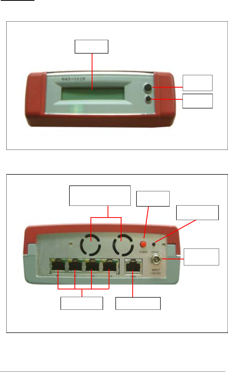
NAS-101R
• Front View
• Rear View
Setting
Switch B
Setting
Switch A
LCD Panel
4 LED Indicators: Power,
Error, Network, and Disk
Access
WAN Connector
Power
Connection
Power
Switch
Configuration Reset
Switch
LAN Connectors

11
• Network Status Indicators
There are five LED indicators at the lower right area of the rear panel. Each LED indicates
the network status of the corresponding WAN or LAN port as below:
Color Indicates
Green Current connection is at 100Mbps. The flashing light
indicates data is being transmitted.
Orange Lights up when connected at 100Mbps. If this LED does not
light up, the connection is running at 10Mbps.
12
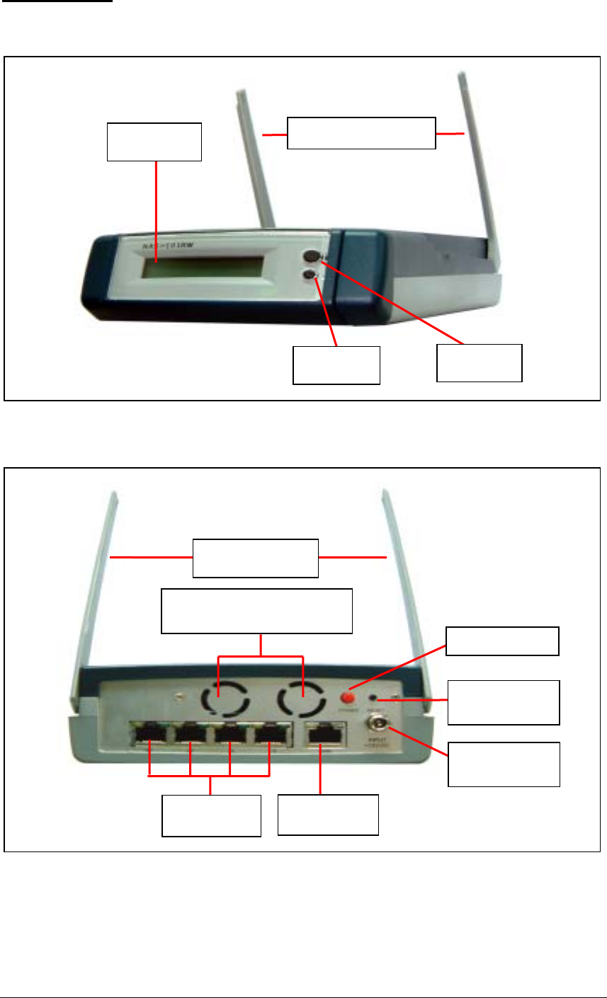
NAS-101RW
• Front View
• Rear View
4 LED Indicators: Power, Error,
N
etwork, and Disk Access
Power
Connection
Power Switch
Configuratio
n Reset
WAN Connector
LAN Connectors
Wireless LAN Antenna
Setting
Switch B
Setting
Switch A
LCD Panel Wireless LAN Antenna

13
• Network Status Indicators
There are five LED indicators at the lower right area of the rear panel. Each LED indicates
the network status of the corresponding WAN or LAN port as below:
Color Indicates
Green Current connection is at 100Mbps. The flashing light
indicates data is being transmitted.
Orange Lights up when connected at 100Mbps. If this LED does not
light up, the connection is running at 10Mbps.
14
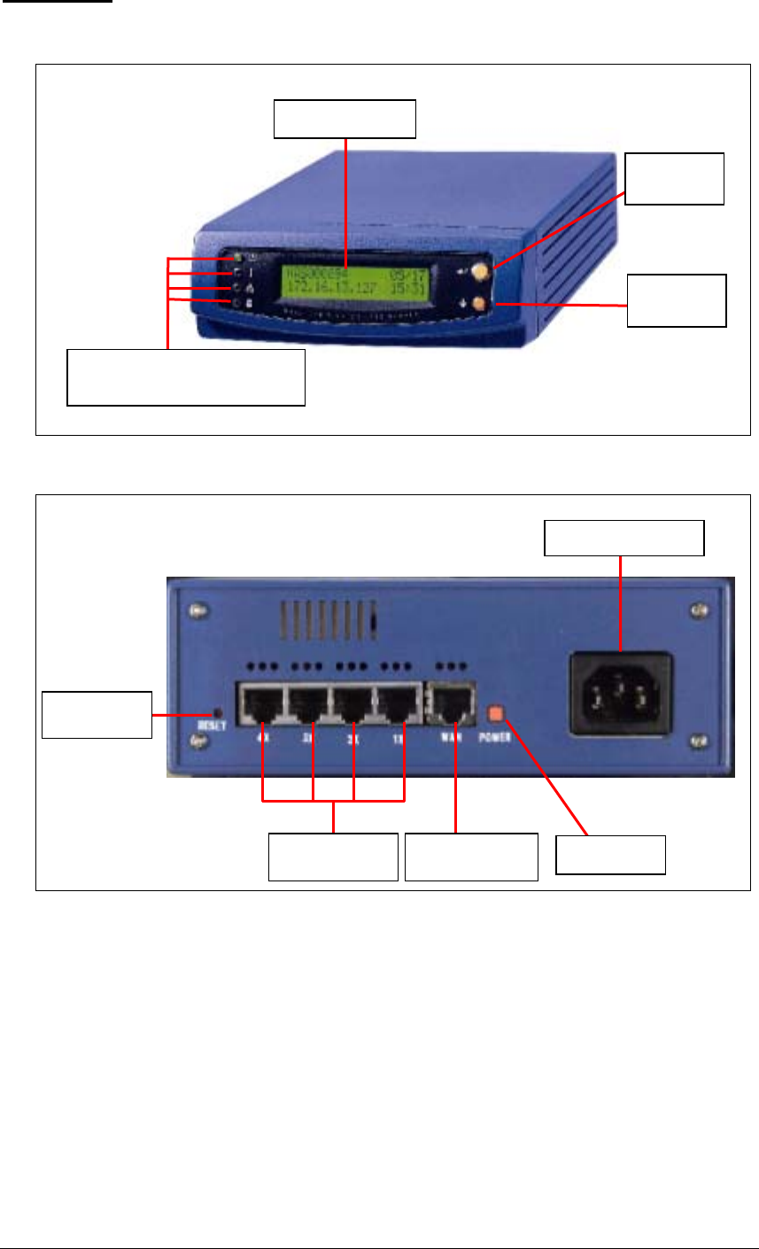
Setting
Switch A
Setting
Switch B
LCD Panel
4 LED indicators: Power, Error,
N
etwork, and Disk Access
NAS-104R
• Front View
• Rear View
LAN (Local Area
Network) Ports WAN (Wide Area
Network) Port
Configuration
Reset Switch
Power Switch
Power Connection
15
• Network Status Indicators
There are five 10/100Mbps network ports on the rear panel of the NAS-104R. Each
port has three LED indicators which describe the network status as follows:
WAN Indicator
Color Indicates
Green Lights up when connected at 100Mbps.
Red Lights up when connected at 10Mbps.
Orange Flashing light indicates data is being transmitted.
LAN Indicators
Color Indicates
Green Lights up when connected at 100Mbps. If this LED does not
light up, the connection is running at 10Mbps.
Red Lights up if the connection is running in Full Duplex mode.
Orange Lights up when connected. The flashing light indicates data is
being transmitted.
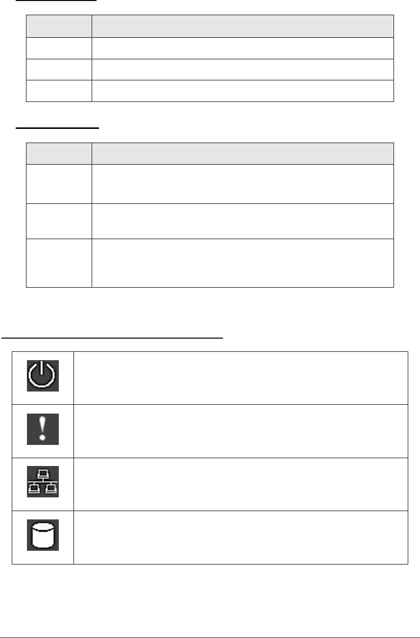
Indicator light at the left of the LCD panel
Shines when power is on
Indicates a system error which needs to be corrected
This light flashes when data is being transmitted through the
network
This light flashes when data is being stored or retrieved from the
disks
16
Installation of the Disk On-line Server
Installing the Hardware
Please follow these instructions to install your Disk On-line Server.
1. Connecting the Disk On-line Server to the Internet
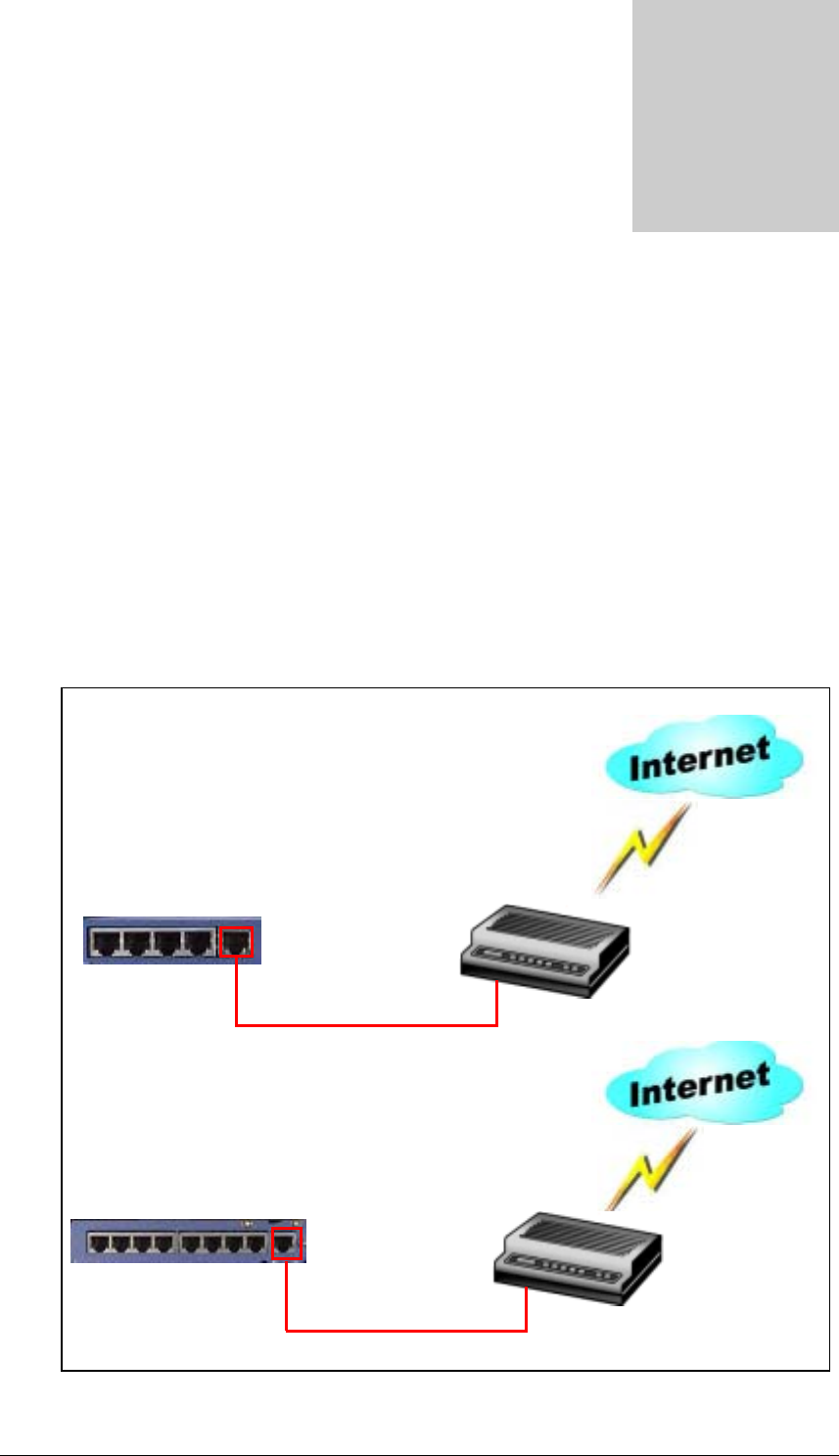
Consult the drawings below to make the connections.
• Broadband Internet Access via DSL Modem
Please use the network cable included with the Disk On-line Server to connect the
WAN port to the DSL modem.
Chapter
2
DSL Modem
NAS-101R / NAS-101RW
/ NAS-104R
NAS-2108R / NAS-2108RW
DSL Modem
CAT5 Network Cable
CAT5 Network Cable
Plug one end of the cable into the WAN port
on the back of the Disk On-line Server, and
the other end to the DSL modem.
17
• Broadband Internet Access via Cable Modem
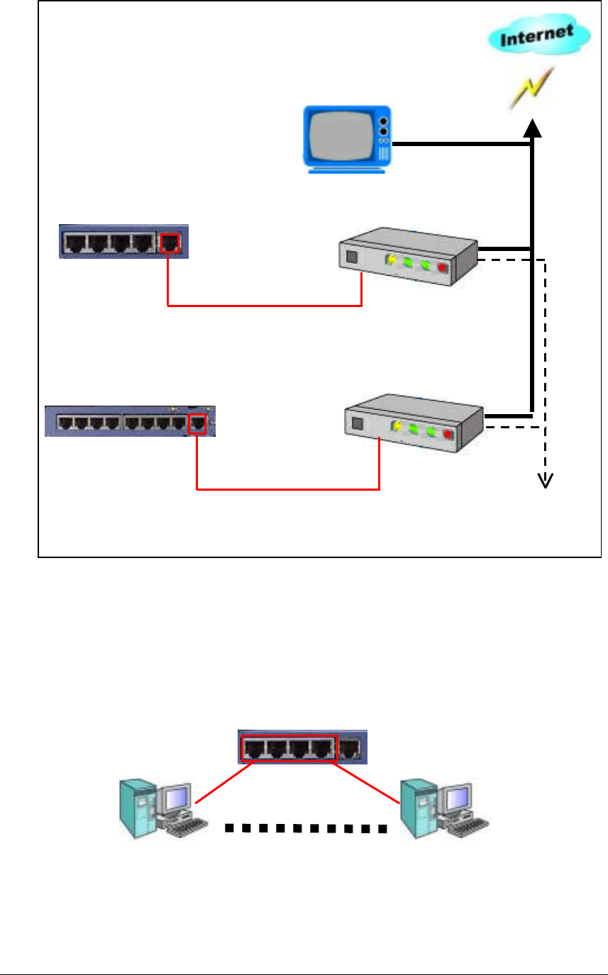
Please use the network cable to connect the WAN port to the cable modem.
2. Connecting the PCs to the Disk On-line Server
Simply connect one end of a network cable from the one of the Disk On-line Server’s
LAN ports in to a network port of your computer.
NAS-101R / NAS-101RW /
NAS-104R
NAS-101R / NAS-101RW /
NAS-104R
Insert one end of the network cable into the WAN port
on the back of the Disk On-line Server and the other end
to the cable modem.
NAS-2108R / NAS-2108RW
Cable Modem
Cable Modem
CAT 5 Network Cable
CAT 5 Network Cable
18
Plug the power cable into the
p
ower receptacle.
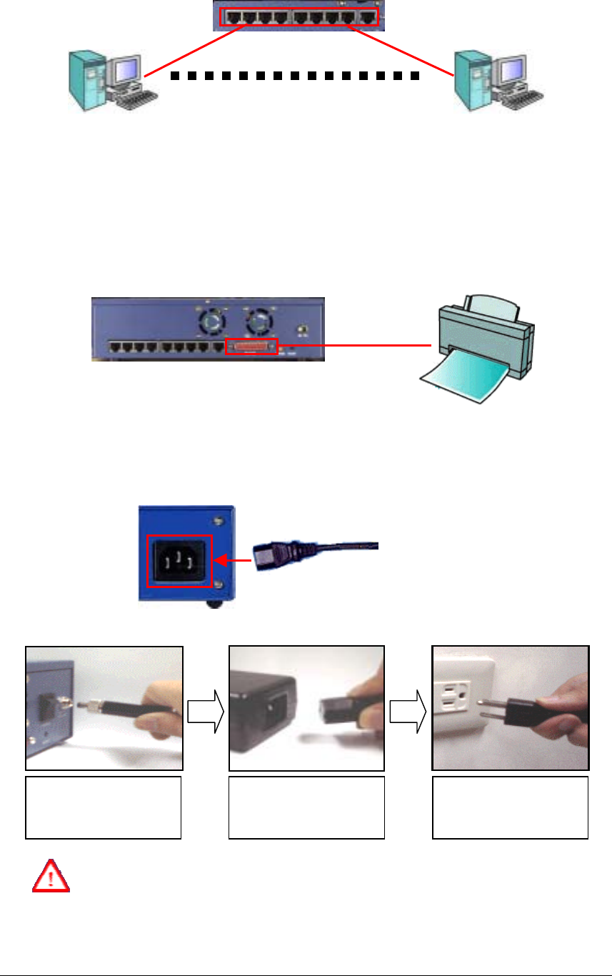
3. Connecting the Printer (For NAS-2108R/NAS-2108RW Only)
The NAS-2108R/NAS-2108RW can provide the function of a network print server by
connecting a printer as shown in the diagram below. Please use the printer cable to
connect the printer to the printer port on the back of the Disk On-line Server. Follow the
software installation procedures described in Chapter 5, and the Disk On-line Server is
ready to print your documents.
4. Connecting the Power
Please refer to the following diagrams to connect the power.
NAS-104R
NAS-2108R / NAS-2108RW / NAS-101R / NAS-101RW
Please make sure the power adaptor is safely secured to the back end of the
NAS-2108R/NAS-2108RW/NAS-101R/NAS-101RW prior to plug-in the
electrical wall socket or extension cord.
NAS-2108R / NAS-2108RW
1. Plug-in the power adaptor
and secure the screw knob. 2. Plug the power cord into
the power adaptor. 3. Then please plug in the
power to the electrical wall
socket or extension cord.
NAS-2108R / NAS-2108RW
19
5. Powering up the Disk On-line Server
Once all the cables have been properly connected, push the power switch on the back of
the Disk On-line Server. The LCD panel will light up and the system is ready for set-up.
At this time the hardware installation of your Disk On-line Server is complete.
Set-up Before First Operation
Before proceed to further configuration, you need to properly adjust the network
configuration of your computers in order to connect to the Disk On-line Server through the
local network.
• Default Network Configuration of the Disk On-line Server
By factory default, your Disk On-line Server will try to build the connection to the
Internet (WAN) via the DHCP protocol. If the Internet connection service that you are
using does not support DHCP protocol, you will need to change the WAN configuration
to successfully connect to the Internet. Please consult your Internet Service Provider (ISP)
or network administrator to get the correct WAN configuration information.
Before you change the WAN configuration, your Disk On-line Server will continuously
try to obtain the external IP address from WAN via the DHCP protocol. However, this
will not affect the connection between the Disk On-line Server and the local computers.
By factory default, the internal IP address of your Disk On-line Server in the local
network is 192.168.1.254, and the DHCP service is activated to perform IP address
allocation and management for local network.
Please make sure the computer is connected to one of the LAN ports on the back of the
Disk On-line Server, and then follow the instruction below to build the connection.
• The Network Configuration of Computers in the Local Network
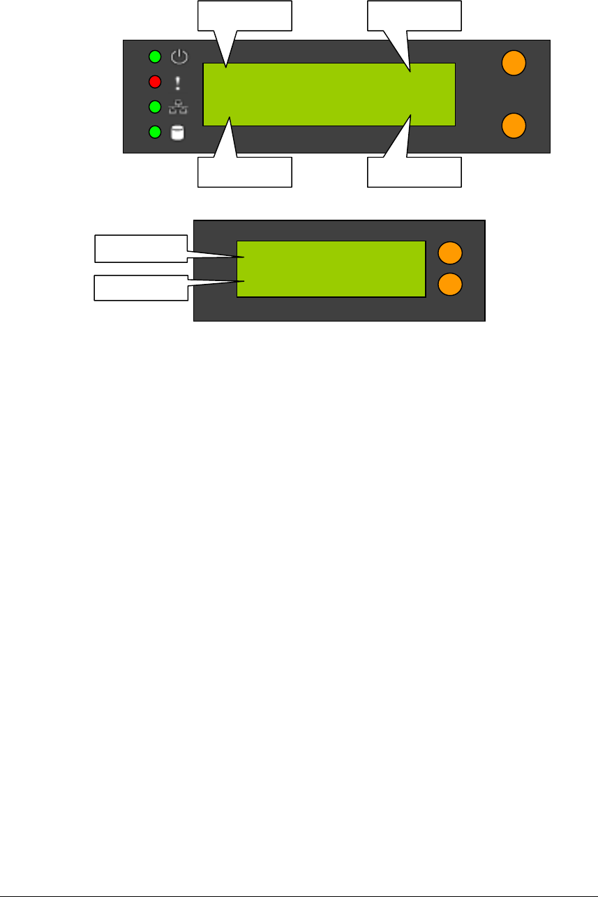
NAS001122 05/22
61.218.32.56 02:48
∃
8
Server Name
IP Address
Date
Time
NAS-2108R / NAS-2108RW / NAS-104R
NAS-101R / NAS-101RW
NAS001122
61.218.32.56
Server Name
IP Address
20
To ease network management, it is suggested that you configure the local computers to
accept dynamic IP addresses assigned by the Disk On-line Server. Please refer to below
illustrations about how to set up local computer network configuration of the local
computer that runs Windows 98 or Windows ME.
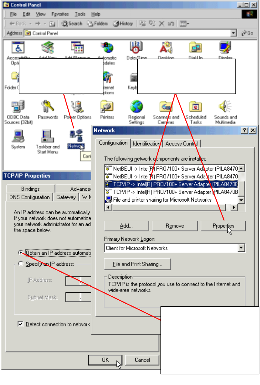
1. Double-click on “Network”
in the Control Panel for a
list of installed network
components.
2. Highlight TCP/IP (if you have
two or more network interface
cards, please select the proper
one) and click on “Properties”.
3. Click on the “Obtain an IP
address automatically” option and
click “OK”. Then return to the
Network dialog and click “OK”
again. You will be asked to restart
your computer. After rebooting,
the computer will use DHCP to
obtain an IP address
automaticall
y
.
21
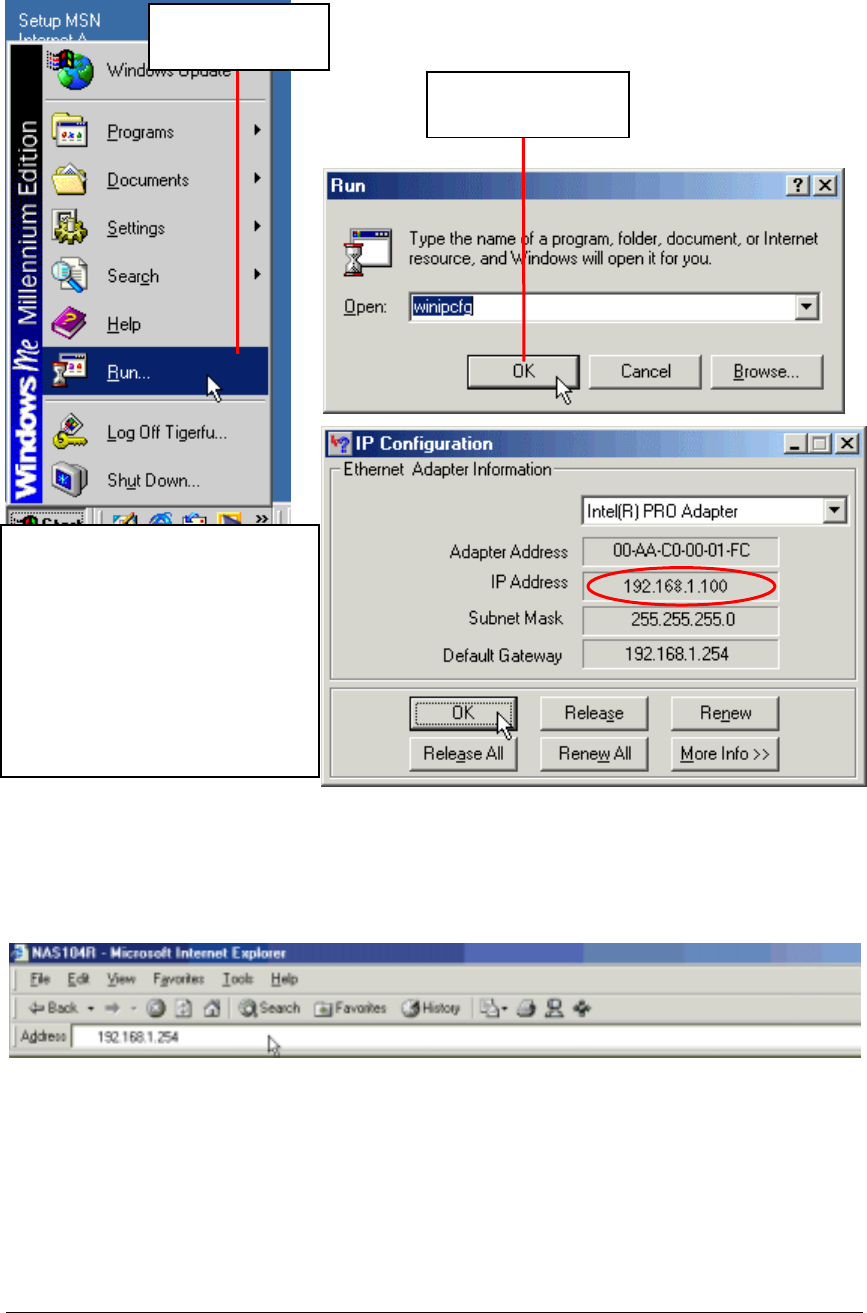
After rebooting, please check to ensure that your computer has successfully obtained its
correct IP address. Below is a description of how this is done in Windows 98 or Windows
ME:
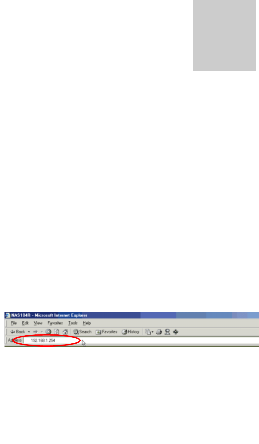
Once these steps have been successfully completed, you can connect to the Disk On-line
Server by typing the default internal IP address (192.168.1.254) in the address bar of your
browser as shown below:
1. Click “Run” in
the Start menu.
2. Type “winipcfg”
and click on “OK”.
3. If the IP address is between
198.168.1.100 and
192.168.1.200, your computer
has obtained a dynamic IP
address successfully. Otherwise,
please make that the network
cable is properly connected to the
LAN port and the network status
indicator on the front of the Disk
On-line Server lights up.
2
1
3
22
Administration of the Disk On-line
Server
Once you have installed the Disk On-line Server and other hardware, and connected it to the
network, you can use your browser (supports Microsoft Internet Explorer 5.0 or later and
Netscape Navigator 4.5 or later; Microsoft Internet Explorer 5.5 is recommended) to
complete administrative tasks for the Disk On-line Server.
Accessing the Administration Page
The following methods allows administrator to access the Administration page:
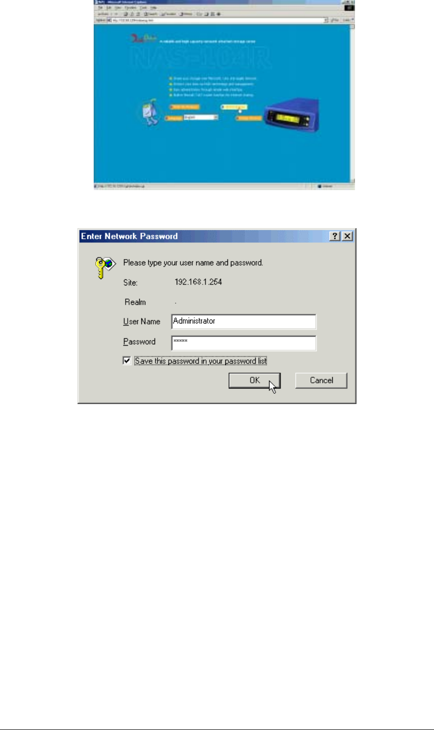
1. Launch your web browser (Microsoft Internet Explorer version 5.5 is recommended). If
you know the IP address of the Disk On-line Server, type the IP address in the address bar
of the browser and press “Enter”. The IP address can also be obtained on the LCD
display of the Disk On-line Server (see Appendix A).
Note: If the computer you are using is connected to the Disk On-line Server via the
LAN port, please type the LAN IP address of the Disk On-line Server (the default
address is 192.168.1.254) in the address bar of the browser. If your computer is
connected to the WAN port, please type the external IP address of the Disk On-
line Server.
2. Use the Quick Installation Wizard (see Appendix C) and double-click on Disk On-line
Server in the list which appears. When the browser displays the home page of your Disk
On-line Server, click on the Administration link.
Chapter
3
23
Enter the user name and password to continue the administration setup.
The factory default login name and password are as follows:
Login: Administrator
Password: admin
If this is the first time you enter the Administration page, the Quick Configuration page
appears automatically. Please refer to the Quick Configuration section for more details.
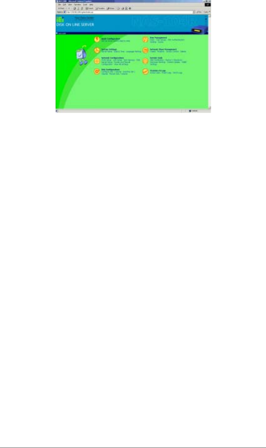
Server Administration
The Server Administration comprise the following eight sections:

24
A
dministration
( Quick Configuration
( System Settings
(Server Name
(Date & Time
(Language Setting
(View System Settings
( Network Settings
(WAN Configuration
(LAN Configuration
(Network File Services (Microsoft Networking
(Apple Networking
(NFS Service
(NetWare Service
(Web Service
(FTP Service
(DNS Service
(Network Printer Service (NAS-2108R/NAS-2108RW Only)
(Router and Firewall Configuration
(Routing Table
(Virtual Server
(One-to-one NAT
(Special Application
(Web Site Filter
(Web Content Filter
(Advanced Firewall Rule
(DMZ
(View Network Settings
(Disk Configuration
(Create Disk Volume (Single Disk Volume
(RAID 1 Mirroring Disk Volume
(RAID 0 Striping Disk Volume
(RAID 5 Disk Volume (NAS-104R Only)
(Linear Disk Volume
(Delete Disk Volume
(Examine Disk Volume
(Format Disk Volume
(View Disk & Volume Status
(User Management
(Users (Create
(Change Password
(Create Private Network Share
(Assign User Groups
(NFS Settings
(Quota Settings
(Delete
(User Groups (Create
(Create Private Network Share
(Assign Users
(Delete
(PDC Authentication Settings
(Quota
(Backup/Restore User Settings
(Network Share Management
(Create
(Property
(Access Control
(Delete
(System Tools
(SNMP Settings
(Alert Notification
(Restart / Shutdown
(Hardware Settings
(System Update
(Change Logo
(Remove Replication
(Statistics & Logs
(Active Users
(Event Logs
(DHCP Logs
Server Administration
25
Quick Configuration
The Quick Configuration will guide you through the configuration process step-by-step, as
follows:
1. Enter the name, workgroup and description for this server.
2. Change the administrator's password.
3. Enter the date, time and time zone for this server.
4. Select the language that this server will use for file names.
5. Enter the IP address, subnet mask and default gateway for this server
6. Select the network file services that you want to provide on this server.
7. Configure disk volume on this server.
8. Configure the method of user authentication.
9. Manage users and user groups for this server.
10. Manage network shares on this server.
Due to different configurations, it might takes from 3 to 10 minutes to complete the Quick
Configuration.
System Settings
Basic system settings include the server name, date, time, and language settings.
• Server Name
You must assign a unique name for your Disk On-line Server for ease of identification
within the local network. The server name can accommodate as much as 14 characters,
which can be a combination of letters (A-Z or a-z), numbers (0-9) and hyphens (-). The

26
server will not accept name containing blank spaces, period (.), or names with only
numbers. The LCD display will show the current server name.
Next, you must configure your Disk On-line Server to the workgroup. The workgroup
represents a basic computer group within the Microsoft Network. Files are normally
shared within the group. Workgroups can accommodate as much as 15 characters but
must exclude the following characters:
; : " < > * + = \ | ? , [ ] /
The first character cannot be a period (.). For ease of management and usage, please set
your Disk On-line Server and attached computer(s) in the same workgroup.
Moreover, the Disk On-line Server allows you to specify comments (such as
administrator name, department, or location) that describe the Disk On-line Server for
ease of identification to an on-line user.
• Date & Time
Set the date, time, and time zone according to your location. If the settings are incorrectly
entered, the following problems may occur:
1. When using a web browser to access or save a file, the time of the file accessed or
saved may be out of sync.
2. The system event log time will be incorrect compared to the actual time an action
occurred.
• Language Setting
The server is based on the language settings and uses it accordingly while creating or
displaying files and directories. Select the correct language settings to avoid the
following problems:
1. Inability to create files or directories with special characters.
2. Inability to display files or directories name with special characters.
Network Settings
The network settings include the TCP/IP configuration for WAN and LAN, network service
settings, router and firewall configuration, etc.
• WAN Configuration
According to your WAN connection, you can choose the following four methods to
configure the TCP/IP settings to the external network:
1. Use PPPoE Protocol
PPPoE is commonly used in DSL-based broadband services to establish the Internet
connection. Please check with you ISP to check if PPPoE is used. You will also need
the user name and password information that supplied by your ISP to properly
configure the PPPoE settings.

27
2. Use PPTP Protocol
If the Disk On-line Server is connecting to a remote PPTP server through the WAN
port, you need to use the PPTP protocol.
3. Use DHCP Protocol
The DHCP protocol is usually used in a Cable modem environment or the intranet.
The system will obtain the IP address settings automatically via DHCP.
4. Use Static IP Address
The fixed IP address is usually used in some DSL broadband services or intranet, and
an IP address must be entered manually in configuring the network. You will need to
enter the following information:
IP Address
The IP address is a 32-bit digit code used to identify each single entity on a network.
The IP address is separated into 4 groups of eight bits separated by dots. (e.g.
61.218.1.5)
Subnet Mask
The subnet mask is used to define computer within the same local network. It is a 32-
bit digit code. (e.g. 255.255.255.0)
Default Gateway
The gateway is generally referred as an interchange point that connects two networks.
If you don’t know the gateway’s IP address, please ask your ISP or network
administrator.
There are several available options in addition to the basic settings:
Allow entering administration web pages from external network
If this option was not enabled, you will not be able to perform system administration from
the computers connected to the WAN port. You may also assign the HTTP port number
for entering administration web pages.
Disable response to ICMP packets to avoid attacks from hackers
For additional security, when enabling this option, outside computers cannot use the 'ping'
program to probe for IP address of this server.
• LAN Configuration
If you use the Disk On-line Server as the gateway to connect to the Internet, there is
normally no need to change the LAN configuration. Simply change the network
configuration of the computers on the LAN to automatically obtain IP addresses via
DHCP protocol. By default, the Disk On-line Server provides the NAT function to allow
the computers on your LAN to share a single WAN IP address for Internet access.
Fixed IP address
The IP address is a 32-bit digit code used to identify each single entity on a network. This
address will be used for all clients in the internal LAN to access this Disk On-line Server.
You can check the current LAN IP address of the Disk On-line Server from the LCD
panel (see Appendix A).

28
Subnet Mask
The subnet mask is used to define computer within the same local network. It is a 32-bits
digit code: 255.xxx.xxx.xxx.
Default Gateway
The gateway is generally referred as an interchange point that connects two networks,
such as LAN and WAN. You don’t need to configure gateway address if NAT function is
enabled; just set it as 0.0.0.0.
Enable DHCP Server
Once the DHCP server function is activated, the Disk On-line Server will assign dynamic
IP addresses to any computer in the local network that is configured to automatically
obtain IP addresses.
Note: Only one DHCP server can be activated at any time in a network, or it may cause
errors in communication.
Enable NAT Function(NAS-2108RW/NAS-101RW Only)
NAT (Network Address Translation) allows the clients that use the internal private IP
address to access the Internet. This option should be enabled if you use the Disk On-line
Server to connect to the Internet.
Wireless LAN Configuration
Your Disk On-line Server is designed to act as an Access Point (AP) in the wireless
LAN. The system is fully compliant with IEEE 802.11b standard, and provides
powerful WEP encryption support for wireless security enhancement.
• Network File Services
Microsoft Networking
Users using the Disk On-line Server on the Microsoft Windows operating systems
must start Microsoft Network Services.
If the local network has a WINS server installed, please specify the IP address. The Disk
On-line Server will automatically register its name and IP address with the WINS service.
Or you can enable your Disk On-line Server as the WINS server for your network.
Apple Networking
Users using the Disk On-line Server on Apple Mac operating systems muse enable
AppleTalk network support.
If your AppleTalk network uses extended networks and is assigned with multiple zones,
please assign a zone name to the Disk On-line Server. If you do not want to assign a
network zone, please enter an asterisk (*). Asterisk (*) is the default setting.
NFS Service
Users using Disk On-line Server on Unix/Linux operating system computer or server
must start Unix/Linux NFS service. The Disk On-line Server supports NFS version 2.0.
To correctly use the NFS service, you must assign a User’s UID and IP address. Please
select User Management · Users · NFS Settings to start the setup.
NetWare Service

29
If you wish to use NetWare to access the Disk On-line Server, you should activate the
NetWare service. The Disk On-line Server will then operate in a manner similar to a
Novell NetWare 3.12 file server.
Web Service
Other than standard OS support, you have the choice to use a web browser to access your
files on the Disk On-line Server. If your Disk On-line server is connected to the Internet
and uses a valid IP address, the Disk On-line Server allows you to access your files using
a web browser from anywhere in the world.
FTP Service
If you wish to download files from or upload files to your Disk On-line Server by using
file transfer protocol (FTP), you must first activate the FTP service.
• DNS Service
DNS (Domain Name System) is used to map a domain name to its corresponding IP
address and vice versa. A DNS server provides the domain name service through the
network. Using this, you can create and manage your domain name in the Internet. If you
do not know how to register a domain name, please contact your ISP. According to your
domain configuration, you can configure the Disk On-line Server as the primary DNS
server or as the secondary DNS server.
Primary DNS Server
The primary name server is responsible for maintaining a list of host name records and
their associated IP addresses. You can add the following name records to your domain:
A Forward Address Record
NS Name Server Record
MX Mail Exchange Server Record
You may also specify the forwarding servers; the Disk On-line Server will forward all
DNS requests that can't be resolved locally to the specified DNS server (typically your
ISP) and return the response to the client.
Secondary DNS Server
The Disk On-line Server can be configured as a secondary DNS server to provide
redundant DNS service for your domain.
• Network Printer Service (For NAS-2108R/NAS-2108RW Only)
The network printer service enables printer sharing via Microsoft or Apple networking.
Please refer to Chapter 5 for detailed procedure to configure the network printer.

30
• Router and Firewall Configuration
Routing Table
The static route defines the network path to reach a specific network or host. You may
need to set up a static route if this system is connected to more than one network.
If you do not have other routers in the network, you will not need to add any static routing
entry. The system will use the default routing table for communication between WAN
and LAN.
Virtual Server
This feature allows you to make the service provided by the internal server accessible to
the users from Internet. The Internet users will then use the WAN IP address of the Disk
On-line Server to access all of your virtual servers.
One-to one NAT
This feature allows you to map an external public IP address to an internal private IP
address hidden by NAT. To use this feature, you will need to have more than one public
IP address from your ISP. You can use this feature to have several servers using internal
IP addresses to be accessed from the Internet.
Special Application
This feature allows you to use some on-line applications that require 2-way
communication or simultaneous sessions. If you use on-line games, conferencing or
messaging software, you may need to configure this function.
Web Site Filter
The web site filter provides a mean to block access to undesirable web sites. If a web site
address is added into web site filter, access to that site is blocked for all clients in the
internal LAN.
Web Content Filter
The web content filter allows you to block access to web sites with undesirable contents.
Advanced Firewall Rule
This feature allows administrators to define a set of rules to examine the network packet
flow between internal LAN and external WAN. By default, all packets from external
networks are denied except for web site requests. No packets from the internal network
are blocked or discarded.

31
DMZ
This feature allows one computer on your LAN to be exposed to all users on the
Internet. This can allow 2-way communication between the DMZ host and other
users from the external network. If you meet troubles to use some Internet gaming or
video-conferencing application on your local computer, you may try to configure this
computer as the DMZ host.
• DDNS Service
DDNS (Dynamic DNS) service allows the Internet users to use a domain name to access
the Disk On-line Server or the servers on your LAN rather than an IP address. This
feature is particularly useful if you are using the broadband service that assigns a dynamic
WAN IP address. To activate the DDNS service, you must first apply an account from a
free DDNS service provider (See Appendix D).
Note: The Disk On-line Server currently supports the DynDNS (http://www.dyndns.org/)
DDNS service.
Disk Configuration
The Disk On-line Server can accommodate a maximum of four disks ( NAS-2108R/NAS-
2108RW can accommodate a maximum of two disks ) . The Disk Volume can be configured
according to your needs.
• Single Disk
You can choose to use a stand-alone disk. However, if the disk is damaged, all data will
be lost.
• RAID 5 Disk Volume (For NAS-104R Only)
Three or more hard disks can be teamed up to form a large-capacity RAID 5 disk group.
This system will distribute and store data among its various member disks as it is received.
At the same time it uses an amount of space roughly equivalent to a whole disk to store
reference numbers with the same elements. Should one of the disks in the group suffer
some kind of damage, you can shut down the computer and install a new disk, and the
system will restore the data on the new disk using the reference number. In addition, if
you have a system with four disks but use only three in your RAID 5 group, the fourth
will serve as a spare disk. If one of the three disks is damaged the system will
automatically start using the spare disk without powering down and changing the affected
disk. Generally speaking, the capacity of a RAID 5 disk group is one disk’s worth of
space less than the total rated capacity of the group.
Note. RAID 5 may be used only with equipment which has three or more disks.
• RAID 1 Mirroring Disk Volume
Mirroring Disk protects your data by automatically backing up the contents of one disk
onto the second disk of a mirrored pair. This protects your data if one of the disks fails.
Unfortunately, the storing capacity is equal to a single disk, as the second drive is used to
automatically back up the first. Mirroring Disk is suitable for personal or corporate use to
store important data.

32
• RAID 0 Striping Disk Volume
Striping disk combines two or more disks into one larger disk. It offers the fastest disk
access but it does not have any protection of your data if the striped array fails. The disk
capacity equals the number of disks in the array times the size of the smallest disk.
Striping disk is usually used to maximize your disk capacity or for fast disk access but not
for storing important data.
• Linear Disk Volume
You can combine two or more disks into one larger disk. During file saving, the files are
saved on physical disks but do not have a disk failure file protection function. The overall
capacity of linear disks is the sum of all disks. Linear disks are generally used for storing
large data and are not appropriate to use for protection of important data.
By factory default, the Disk On-line Server has been pre-set into one large disk. If you wish
to use other disk configurations, the settings can be changed during the first Quick
Configuration access. Furthermore, to increase the hard disk life, the hard disk will go to
standby mode if there is no access within 30 minutes. If any data access happens while the
hard disk is in stand-by mode, it will take 3 or 5 seconds for the hard disk to return to normal
mode. You can select System Tools · Hardware Settings to change the setting.
You can also perform the following disk administration:
• Create Disk Volume
• Delete Disk Volume
• Examine Disk Volume
• Format Disk Volume
• View Disk & Volume Status
User Management
The Disk On-line Server can share its files with multiple users. It is important to plan and
organize users and user groups’ accessibility to ease the administration work.
• User
The factory default settings contains the following user settings:
Administrator
By default, the Administrator is a member of the Administrators group and has access to
the system Administration. You cannot delete the user Administrator.
Guest
When you use a non-registered user name to login, the server recognizes it as a guest and
will allow limited access. A guest does not belong to any user group. You cannot delete
the user guest or create a password.

33
Anonymous
When you connect to the server by FTP service, you can use the name to login as a guest.
You cannot delete this user or change its password.
You can create a new user according to your needs. The following information is required
to create a new user:
• User Name
The user name must not exceed 32 characters. It is case insensitive and it can contain
double-byte characters (Such as Chinese, Japanese, and Korean) But it cannot contain
any of the characters below:
" / \ [ ] : ; | = , + * ? < > ` '
• Password
The password must not exceed 16 characters. Due to security concerns, the password
must be at least 6 characters. Try to avoid using codes that are easily decipherable.
You can perform the following settings for users:
• Create User
• Change Password
• Create Private Network Share
• Assign User Groups
• NFS Settings
• Quota Settings
• Delete User
User Groups
To administer access rights, you can create user groups. User groups are a collection of
users with the same access rights to files or folders. By factory default, the server
contains the following pre-defined user groups:
Administrators
All members of the administrators group have the rights to perform system management.
You cannot delete the administrators user groups.
Everyone
All registered users belongs to everyone group. You cannot delete the everyone user
group or any of its users.
You can administer user groups with the following:
• Create User Groups
• Create Private Network Share

34
• Assign Users
• Delete User Groups
User groups name must not exceed 256 characters. It is case insensitive and it can
contain double-byte characters (Such as Chinese, Japanese, and Korean) But it cannot
contain any of the characters below:
" / \ [ ] : ; | = , + * ? < > ` '
To properly manage security, it is very important to manage users and user groups. You
may set the share access parameters of each user or user group accordingly.
• PDC Authentication Settings
If you have a Windows PDC (Primary Domain Controller) server to handle the domain
security in your network, you don’t need to re-enter all the users and groups with the Disk
On-line Server. You can simply enable the PDC authentication feature; the Disk On-line
Server will connect with the NT domain and get all the information of the domain users
and groups automatically.
To enable PDC authentication, you must enter the domain name as well as the user name
and password already established in this domain. The Disk On-line Server will use the
user name and password to log in to the NT domain and retrieve user and group
information. Once you have configured the Disk On-line Server to use PDC
authentication, all NT domain users and groups will appear in lists of users and groups for
which you can define access rights.
Note: NetWare users cannot be authenticated via the PDC server. To properly
authenticate NetWare users, please go to User Management · Users · Change
Password page and type the password for that user manually.
• Quota
The amount of space given out to all users in the system can be limited in order to
manage and allocate it efficiently. Once these restrictions are in place, users will be
prevented from obtaining more space once they have reached their limit. This prevents
monopolizing of a large amount of disk space by a small group of users. No limitations
are set on the system when it leaves the factory.
• Backup/Restore User Settings
You may back up all user settings on to your computer as well as restore previously
backed up user settings file to your Disk On-line Server. This function allows you to
easily maintain the user settings.
Network Share Management
The primary purpose of network storage is file sharing. In a standard operation environment,
you can create different network share folders for various types of files, or provide different
file access rights to users or user groups. By factory default, a “public” share folder is
created. The share folder gives full access to all users or guests.
Administer network shares with the following:

35
• Create a Network Share
• Change the name, path and comment of a network share
• Set access right for a network share
• Remove a network share
You can create new network shares according to your needs. While creating a network share
the following parameters must be set:
• Network Share Name
The network share name must not exceed 12 characters. It cannot contain double-byte
characters (such as Chinese, Japanese, and Korean) as well as the characters listed below:
" . + = / \ : | * ? < > ; [ ] %
• Disk Volume
The network share will be created under the specified disk volume.
• Path
All data are stored under the assigned path onto the disk volume. You can select Specify
Path Automatically to allow the server to automatically create a new path on the disk
volume to store the network share files. Or you can assign a specific path for the share
folder. The manually assigned path cannot exceed 256 characters and cannot contain the
characters listed below:
" \ : | * ? < > ; ` '
• Comment
The Comment field allows a brief description of the share folder to help users identify its
purpose in a network neighborhood window. The comment cannot exceed 128 characters.
Once the network share is created, you can start assigning access rights to users or user
groups:
• Full Access
Full access allows the user or user group to read, write, create, or remove all files and
directories in the network share.
• Read Only
Reads files only in the network share but denies functions to write, create or delete files or
directories.
• Deny Access
Denies all files on the network share.

36
System Tools
The following system tools allow optimized maintenance or management of your Disk On-
line Server:
• SNMP Settings
In order to use Simple Network Management Protocol (SNMP) to manage the Disk On-
line Server's network components, the SNMP service must be started.
• Alert Notification
Configures administrator’s e-mail address and SMTP server’s IP address. In case of
warning or malfunction, an email is automatically sent to the administrator.
• Restart / Shutdown
Powers off or restarts the Disk On-line Server.
• Hardware Settings
You can enable or disable the following hardware functions of your Disk On-line Server:
1. Enable LCD panel setting function
Allow you to change the TCP/IP configuration using the LCD panel buttons.
2. Enable configuration reset switch
Depress and hold on the configuration reset switch for 5 seconds to reset the
administrator password and network settings to the factory default.
3. Enable hard disk standby mode
Hard disk will go to standby mode if there is no access within the period you specify.
4. Enable buzzer
If the buzzer is disabled, it will not sound when a system error occurs, but the warning
light will still shine.
• System Update
Performs system software updates. Make sure that the image file that you are about to
update is the correct version and read through the instructions carefully. It is wise to back
up all existing data on the Disk On-line Server prior to performing system software
update. The current settings will remain unchanged after the system is upgraded.
• Change Logo
You can place a picture that you desire on the upper right corner of the home page. The
size of the picture cannot exceed 20K.
• Remote Replication
User can backup data from local NAS to another NAS without backup software. It can
provide schedule Full/Incremental/Sync remote replication.

37
Statistics & Logs
You can monitor the current logon user of the Disk On-line Server and the system event logs
for the purpose of user administration or system diagnostic reference.
• Active Users
Displays information of all online users.
• Event Logs
The Disk On-line Server can store thousands of recent event logs, including warning,
error and information messages. In the event of a system malfunction (LCD error
indicator lights up), the event logs can be retrieved to help diagnose the system problem.
• DHCP Logs
If the DHCP server function is activated, you can use it to monitor all of the assigned
dynamic addresses, client MAC addresses and other information.

38
Accessing the Disk On-line Server
Using Microsoft Windows
Under the Microsoft Windows operating system, you can access the Disk On-line Server
using the following steps:
1. Use the locate and connect the Disk On-line Server within the local network:
• Click on the Start button and select Run in the Windows menu bar. Enter the name
of the Disk On-line Server, for example:
\\NAS004001
and press Enter.
• You may also look for the Disk On-line Server within the Network Neighborhood.
Locate the workgroup and find the name of your Disk On-line Server. When the server
is found, double-click on the server name to connect.
• You may also use the “Search for Computers” function to look for your Disk On-line
Server in Windows. Under Windows ME or Windows 2000, please follow these steps:
1. Open “My Network Places” folder.
2. Under the tools bar menu click “Search”.
3. Computer Name path key-in Disk On-line Server name.
4. Click once on Search.
Once the Disk On-line Server is found, double-click your mouse button on the icon to
connect.
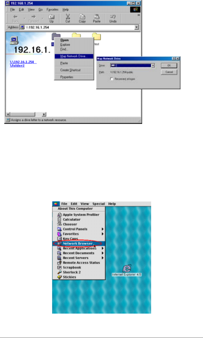
2. Once the connection to the Disk On-line Server is successful, all listing on your available
network share are displayed. Move the mouse pointer to the network share you want to
access and click the right button once. A popup menu appears; select “Map Network
Drive”. A popup window that allows you to assign a drive letter for the network share
appears (note: do not use the drive letter used by the CD-ROM). If you wish to make the
share folder available for your next start-up, check the “Reconnect at logon” box on the
popup window and click on “OK” to make the network share as one disk drive in your
system.
Chapter
4
39
3. Once the network share is a part of your system disk drives, you can locate the network
share in “My Computer” and access it as a regular hard disk drive.
Using the Apple Mac Operating System
If you are a Mac OS user, you can use the following two methods to access to your Disk On-
line Server:
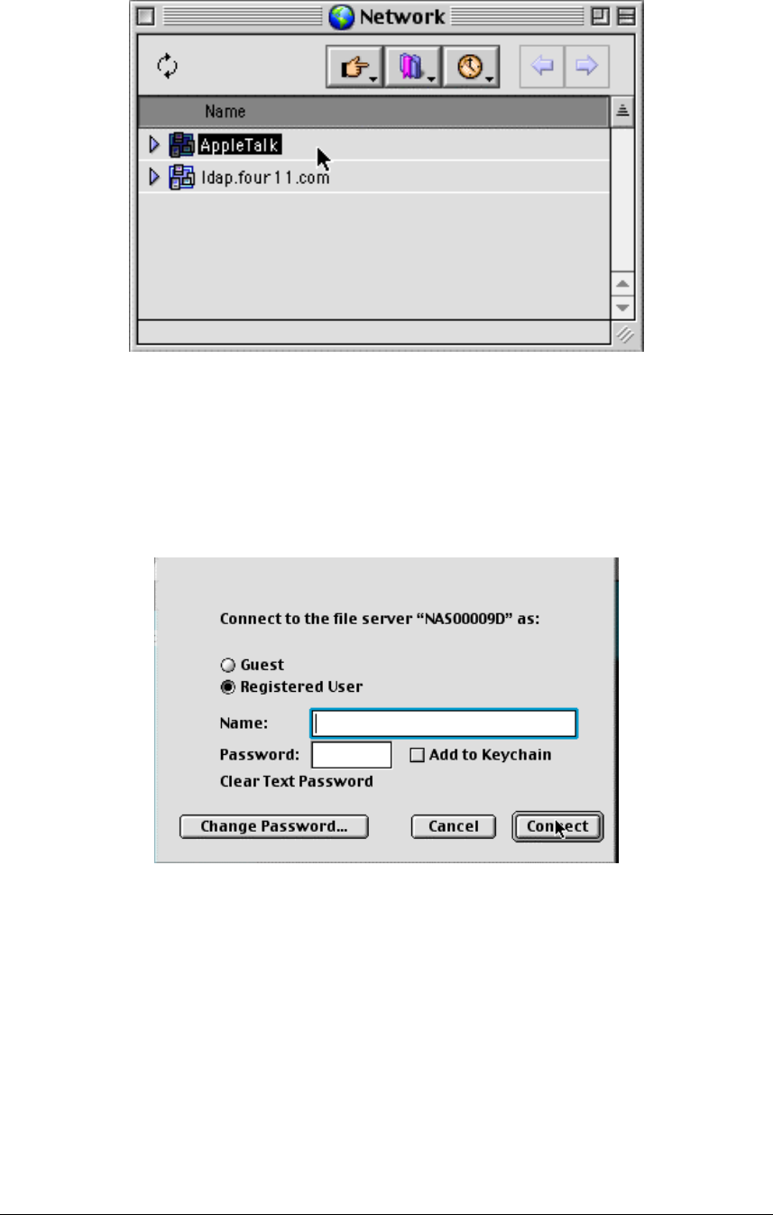
1. Using Network Browser
a. Choose “Network Browser” in the Apple menu.
40
b. In the “Network Browser”, choose AppleTalk; a list of all computers on the
AppleTalk network appears. Choose the Disk On-line Server.
c. Once the Disk On-line Server is chosen, the system will request you to input the
login name and password. Click “Connect” or use “Guest” to enter. When the
login name and password are confirmed, a popup window informs you that the
connection is made with the Disk On-line Server.
41
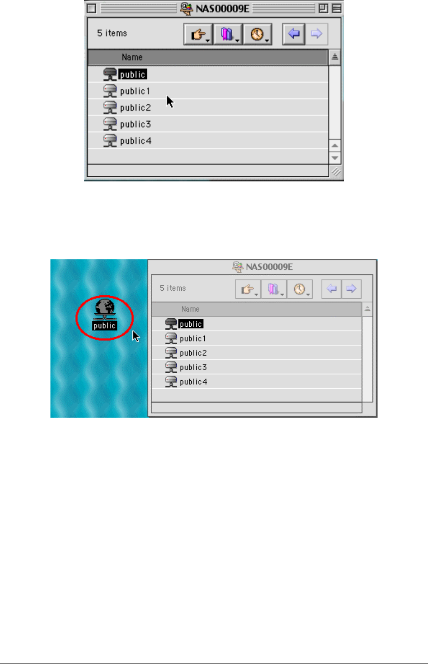
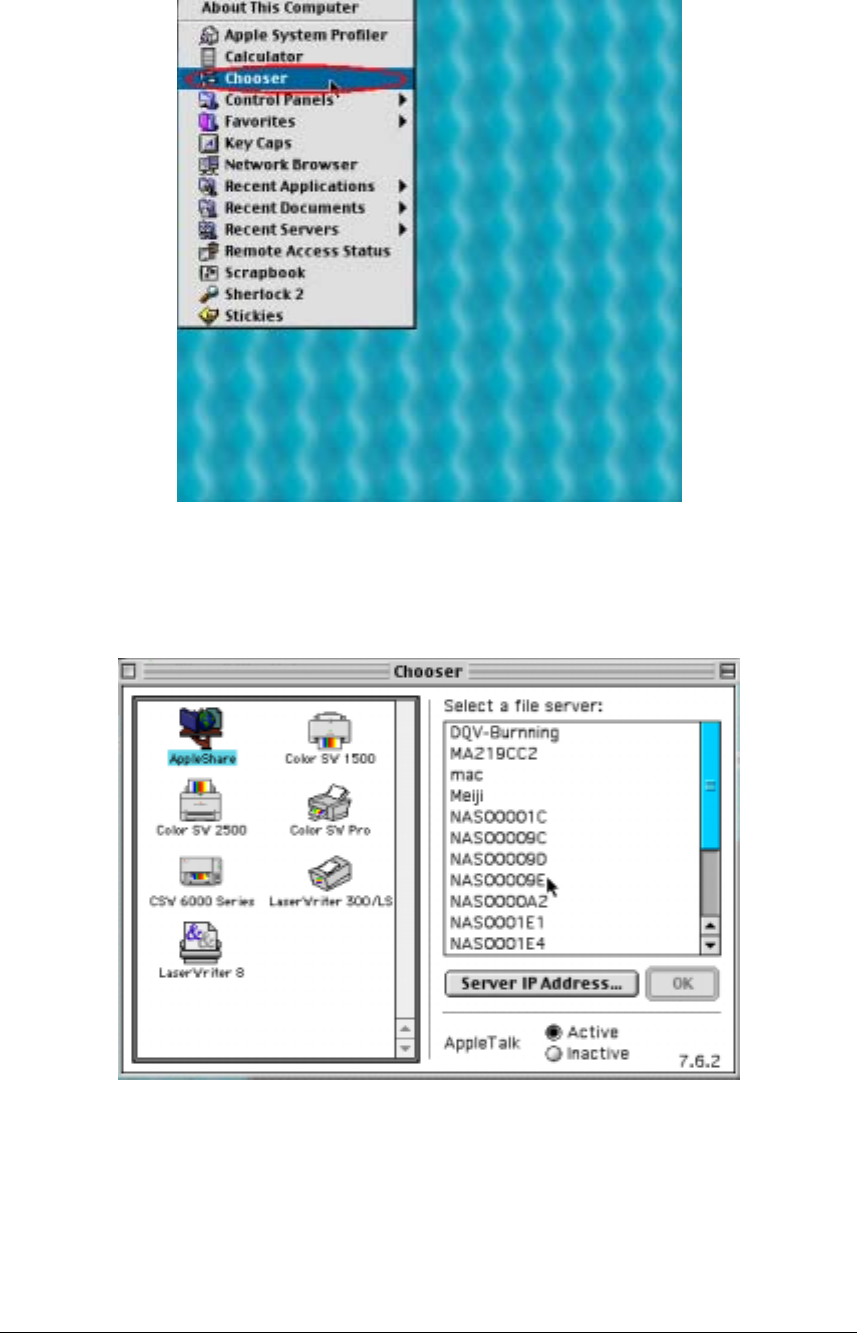
d. When the Disk On-line Server is connected, the network browser displays all the
network shares. You can then access or drag & drop the share folders.
e. Choose either one of the network shares to start to link. The network share
appears on the Mac OS desktop.
42
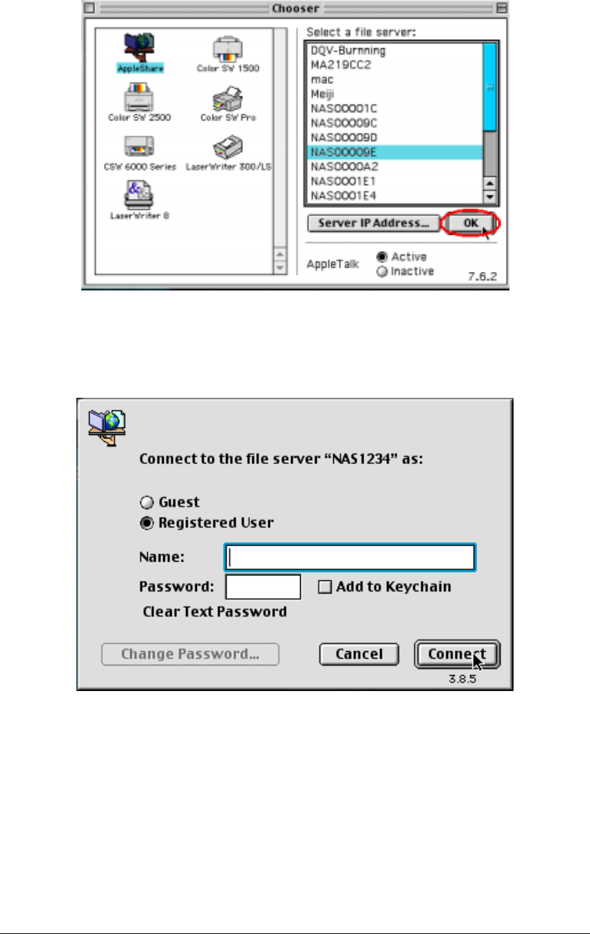
2. Using the Chooser
a. Select Chooser in the Apple menu bar.
b. Click on AppleShare. The name of the Disk On-line Server appears on the right
side of the window.
43
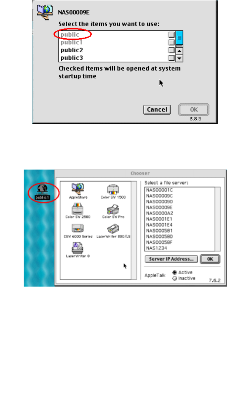
c. Use the mouse to highlight the Disk On-line Server and then click on the “OK”
bottom right-hand side of the screen.
d. Enter the correct login name and password or use “Guest” to login, then click on
“Connect”.
44
e. All available network shares will be listed. Use the mouse to choose a network
share and click on “OK”.
f. You can then close the Chooser program. Double click on the icon on the desktop
to access your files.

45
Using the Unix/Linux Operating System
Other than Microsoft OS and Mac OS, your Disk On-line Server supports Unix based
systems (such as IBM AIX, HP-UX, Sun Solaris, Linux, Free BSD, etc) through the NFS
service:
1. Under Unix, use the following commands:
mount -t nfs <Disk On-line Server IP address>:/<Network Share Name> <Directory
to Mount>
For example, if your Disk On-line server’s IP address is 192.168.0.1 and you want to
link the network share folder “public” under the /mnt/pub directory, use the following
command.
mount -t nfs 192.168.0.1:/public /mnt/pub
Note: You must login as “root” user to initiate the above command.
2. Logged in as the user id that you defined, you can use the mounted directory to access
your network share files.
For more information about NFS settings, please refer to your Unix system documentation.
Using Novell NetWare
If you are accessing the Disk On-line Server from the NetWare client, please refer to the
NetWare user’s manual for more information. The Disk On-line Server functions as a
NetWare 3.12 file server.
Using a Web Browser
Other than OS support, your Disk On-line Sever also provides a convenient web style file
management that allows using a standard web browser to access your data. If you link the
Disk On-line Server onto the Internet and use a public IP address, you can logon to access
the files from anywhere in the world.
For more information, please refer to Appendix B.
Using File Transfer Protocol (FTP)
In addition to working with multiple operating systems, the Disk On-line Server also
supports FTP. You can use popular FTP software and enter the user name and password to
connect to the Disk On-line Server. Or you may key in anonymous as the user name in order
to access public network share folders that is open to guest users.
46
Installing the Network Printer
(For NAS-2108R/NAS-2108RW Only)
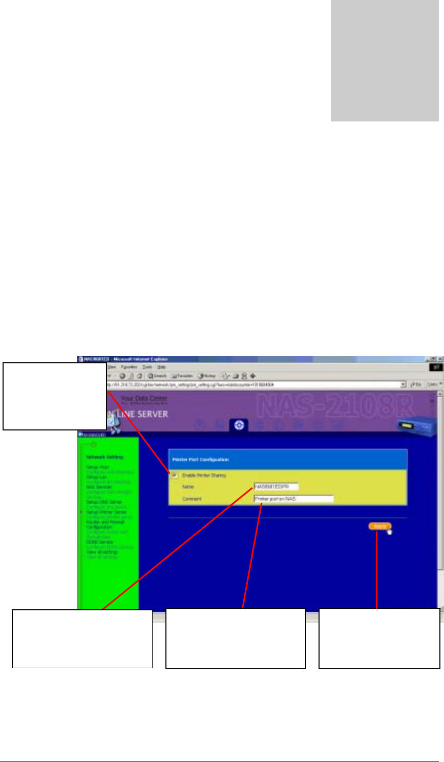
Enabling Network Printer Service
To enable the print server function, please connect the printer to the printer port on the rear
panel of your Disk On-line Server. Then enter the system administration web page via the
browser, go to Network Settings.Network Printer Service to enable the network printer
service.
Chapter
5
Check the “Enable
network printer
service” option to
enable the print server
function.
Please enter a brief description
about this network printer. After updating all settings,
please click on “Apply” to
accept changes.
Please enter the name for this
network printer. You can see the
network printer name in Microsoft
or Apple networking.
47
Setting Up the Printer on Your Computer
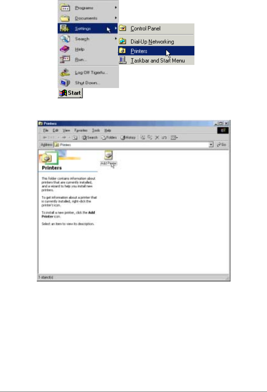
You will need to install the network printer on your computer. On a Windows 98 or
Windows ME platform, please follow below procedure:
1. Select “Settings” in the Start menu and click on “Printers”.
2. Click “Add Printer” to run the Add Printer Wizard.
2
1
48
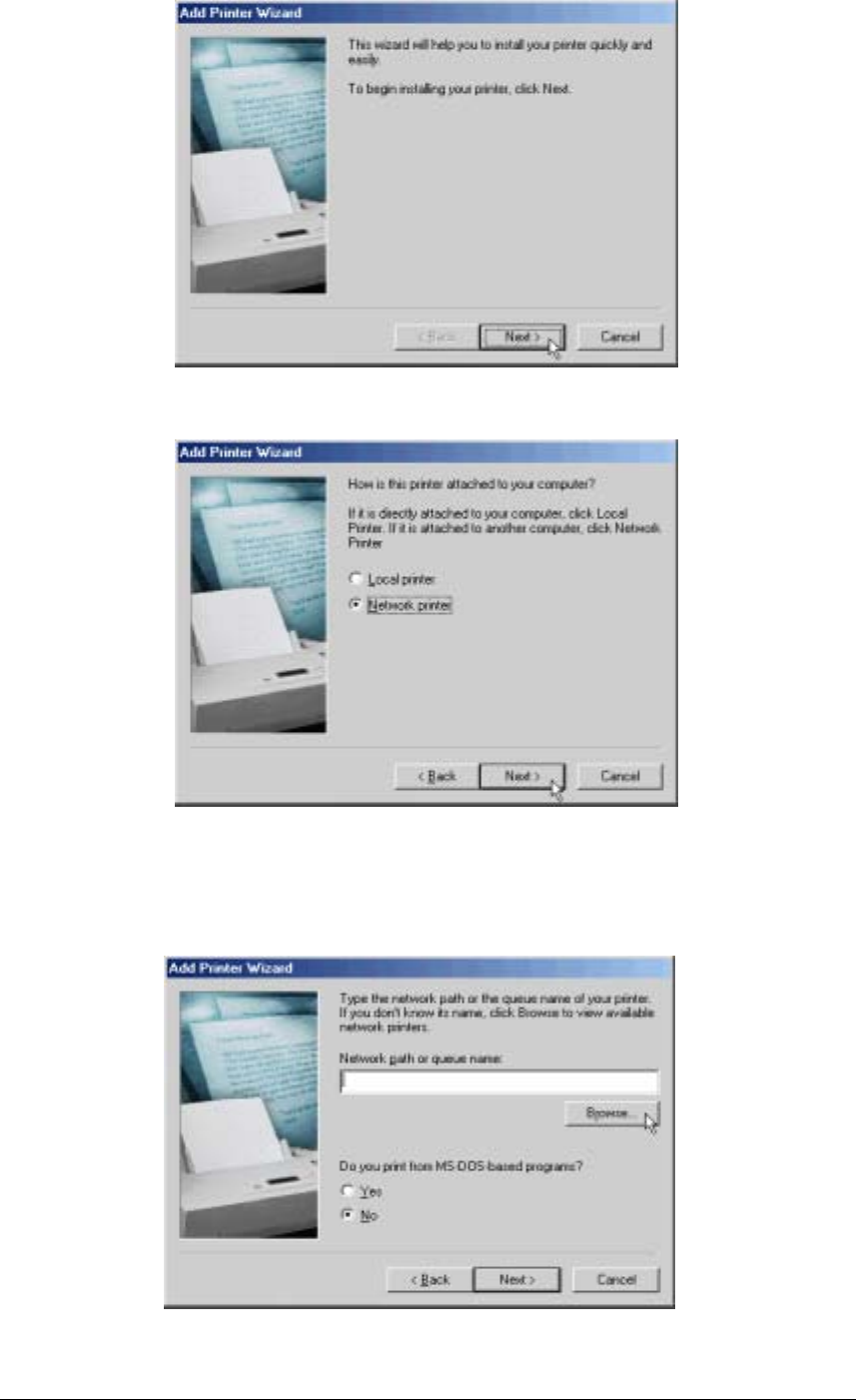
3. Follow the on-screen instruction and click “Next”.
4. Choose “Network printer” and click “Next”.
5. Enter the network path or queue name for the printer, or click on “Browse…” to view
available network printers. If you enter a path or queue name, skip to step 7. Or you may
click “Browse…” to locate the printer.
5
4
3
49
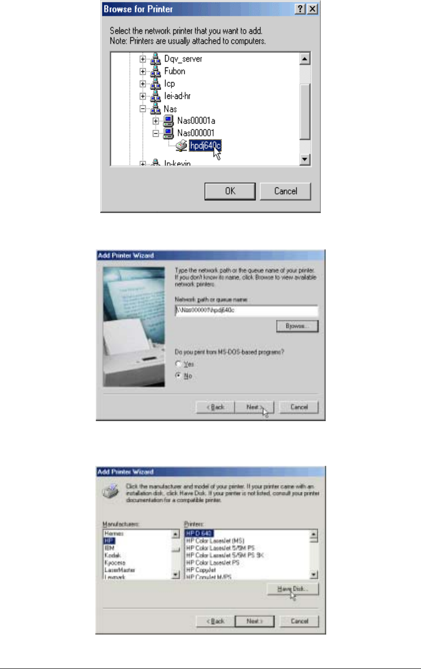
6. Please find the Disk On-line Server within the network neighborhoods. Select the printer
icon under your Disk On-line Server and click “OK”.
7. Verify the network path and click “Next”.
8. You will be asked to choose the driver for your network printer. Please follow the on-
screen instructions to install the driver.
7
6
8
50
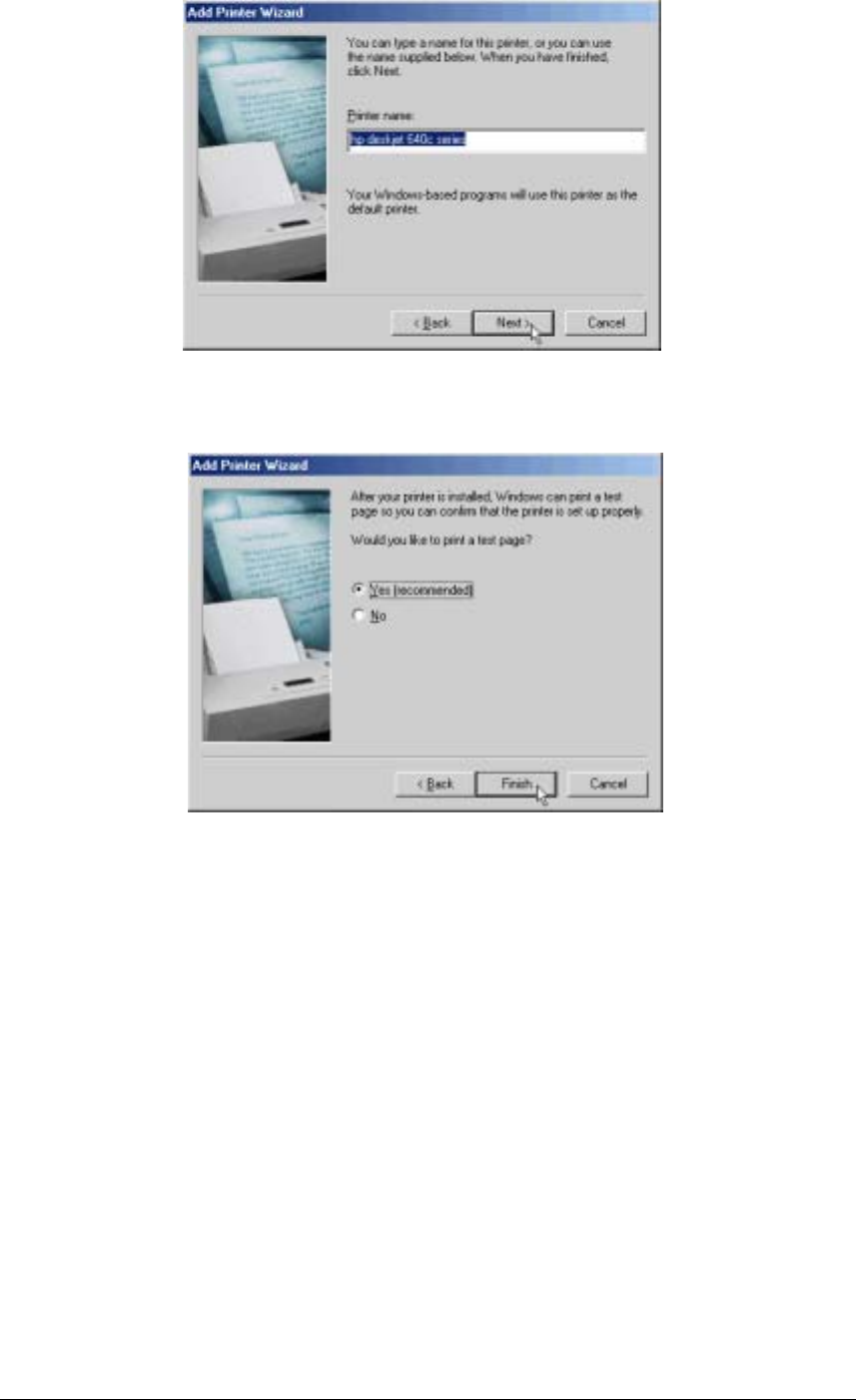
9. Enter the name for your printer and click “Next”.
10. Click “Finish” to print a test page.
11. Please verify if the test page was printed successfully. If you find any problems, please
consult the trouble-shooting guide or user’s manual of the printer.
8
9
10

51
Disk On-line Server - Maintenance
The Disk On-line Server has been specially designed to run on 24 hours, 7 days a week and
to be ready at all times. It is also robust to protect against system crashes caused by power
loss. This section provides a general maintenance overview.
Shutdown/Restart the Server
Please use the following steps to shutdown/restart the server:
1. Ask all the connected users to save their working files and stop using the Disk On-
line Server.
2. Open the administration web page and go to System Tools · Restart/Shutdown.
Follow the instructions to restart or shutdown the system.
Reset the Administrator Password & Network
Settings
If you accidentally forget the administrator password, you will not be able to perform any
administration work on the Disk On-line Server. Under this condition, you can reset the
administrator password and network configuration to the factory default.
1. Use the tip of a ball point pen and depress the configuration reset switch located on
the back of the Disk On-line Server. Hold it for about 5 seconds until the beep.
2. The network configuration will be reset, and you may need to re-configure some or
all of the network settings before you can connect to the Disk On-line Server.
3. Use a web browser to connect to the Disk On-line Server. Enter the System
Administration and enter the following login name and password.
Login: Administrator
Password: admin
You can then perform system administration.
Note: If the configuration reset switch is disabled in the System Tools · Hardware
Settings page, you are no longer able to use this function. Please remember your
administrator password.
Chapter
6

52
Disk Failure or Malfunction
If you are suffering from a disk failure or malfunction, please do the following:
1. Log all abnormal events or messages for technician’s reference.
2. Stop all operations of the Disk On-line Server and power it off.
3. Contact the customer service for technical support.
Note: Your Disk On-line Server must be repaired by a trained technician. Please do not
try to repair the Disk On-line Server on your own.
Power Outage or Abnormal Shutdown
In the event of power outage or abnormal shutdown of the Disk On-line Server, the system
should return to its original state prior to shutdown or power outage after restart. If the
system is not operating within normal parameters, please proceed with the following steps:
1. In the event of system configuration setting lost during power outage or abnormal
shutdown, please manually reset your desired configurations.
2. In the event of abnormal operation or an error message, please contact customer
service for support.
To prevent similar occurrences, we suggest that you periodically backup all critical files or
folders and remember the following tips:
1. Follow Shutdown/Restart the Server steps described above for normal shutdown or
restart.
2. If you are able to anticipate power outage, please backup all critical files or folders
prior to power outage and shutdown your server normally. Restart your server once the
power has returned to normal.
To prevent major data lost of data in the event of a disk failure, please back up your
data periodically.
53
LAN IP ADDRESS
192.168.1.254
DISK NUMBER:1
SIZE: 38361.08MB
NAS2108R
2.11
(
0311
)
Appendix A LCD Panel
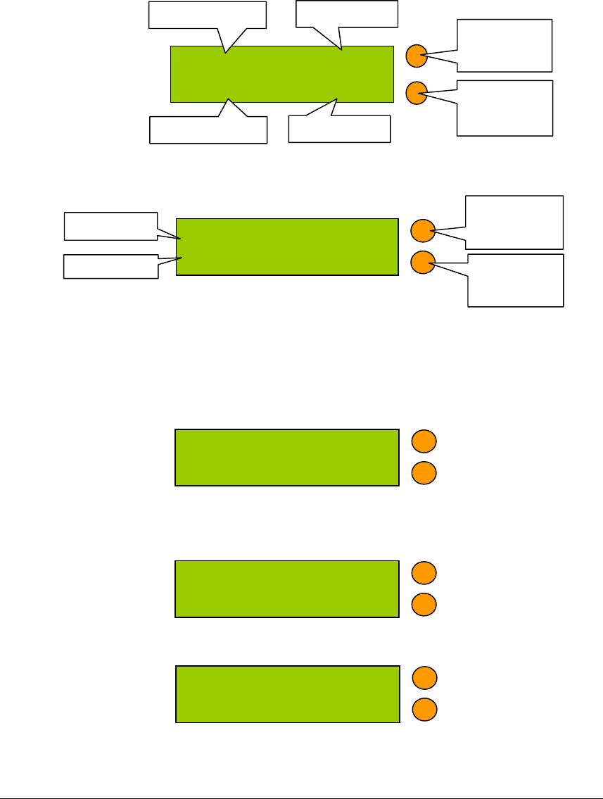
Displayed Information
After system powers on, the following information is displayed on the LCD panel:
NAS-2108R / NAS-2108RW / NAS-104R
Checking IP Address, System and Disk Information
Press B to display the internal IP addresses of this Disk On-line Server in the local network.
Computers connected to the LAN ports can access the Disk On-line Server via this IP
address.
Click on B again to show the available disk space. Please note that this is actually the entire
amount of disk space, and not the amount of space that you can use.
Click B again to display the model number and version information as shown below:
NAS-Router 05/22
61.235.61.33 02:22
Server Name
WAN IP Address
Date
Time
Setting Switch
A (Button A in
the text below)
Setting Switch
B (Button B in
the text below)
NAS001122
61.218.32.56
Server Name
Setting Switch
A (Button A in
the text below)
Setting Switch
B (Button B in
the text below)
IP Address
NAS-101R / NAS-101RW

54
System Setup Function
Entering a System Page
1. Press the switch A for two seconds to enter System Setting.
2. Press the switch B for selection options.
3. Press the switch A to enter the selection options.
NETWORK SETTINGS
After enter the Network Settings menu, please press the switch B to choose DHCP or
Static IP.
1. DHCP - Obtain IP Address Automatically
The Disk On-line Server will automatically obtain the IP address settings via
DHCP protocol.
2. STATIC IP - Specify Static IP Address
Press the switch A to select STATIC IP and complete the following steps:
• SET STATIC IP
Press the switch B to set the IP address settings (press the switch B to select the
number 0~25). Press the switch A for the next number.
• SET NETMASK
Follow the same procedure as above.
• SET GATEWAY
Follow the same procedure as above.
• SELECT STATIC IP
Press the switch B to select YES or NO and confirm by pressing the switch
A.NO will return to the Network Settings menu.
• RESTART SYSTEM
You need to restart the system to make changes effective. Press the switch B to
select YES or NO and press the switch A to confirm.
POWER DOWN
Press the switch A to shutdown the system.
REBOOT SYSTEM
Press the switch A to reboot the system.
EXIT
Press the switch A to exit the settings menu.
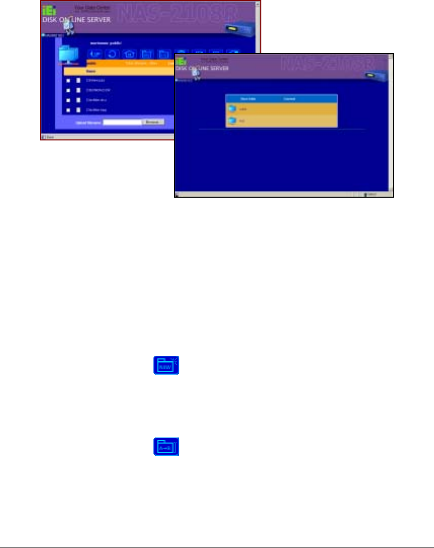
55
Appendix B Web File Manager
Using Web File Manager
Start your web browser and enter your Disk On-line Servers home page. Select Web File
Manager and enter the correct login name and password. You may also enter “guest” in
the login name field with no password to access the network shares on the Disk On-line
Servers as an anonymous guest.
The Disk On-line Servers allows you to organize your network share folders on-line. You
can save these files inside folders as well as rename and remove files or folders.
• How to View Files On-line
Click on a file displayed on the web page. The file’s data are displayed on the browser. If
your browser does not support the file format, the download window pops up
automatically. Once the file is downloaded, you can open it on your computer.
• How to Create Folders
1. Enter the folder that you want to create the new folder.
2. On the tool bar, click on (Create Folder).
3. Enter the name of the new folder and confirm.
• Renaming Files or Folders
1. Select the file or folder you want to rename.
2. On the tool bar, click on (Rename).
3. Enter the new file or folder name and confirm.
• Deleting Files or Folders
1. Check the file(s) or folder(s) you wish to delete.

56
2. On the tool bar, click on ( Delete ).
3. A window appears. Click on OK to delete the selected file or folder.
To delete all files and folders, click on (Select All), then click on (Delete).
• Uploading
1. Enter the folder of the file you want to upload.
2. Click on “Browse…” to select the file you want to upload.
3. Click on “Upload”.
• Downloading
1. Click the right mouse button on the file which you want to download.
2. A context menu appears. Click on “Save Target As…” to download the file.
• Logging Out Web File Manager
On the tool bar, click on ( Logout ) to leave the web file manager.
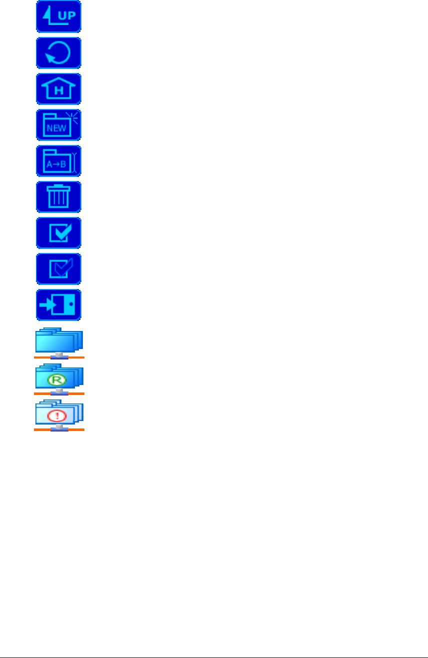
57
Web File Manager Icon
Up - go back to the parent folder
Refresh – reload the current page
Home - go back to the network shares list home page
Create Folder – create a new folder
Rename – rename the selected file or folder
Delete – remove the selected file(s) or folder(s)
Select All – select all files and folders
Select None – cancel all selection
Logout – leave the web file manager
Full access network share folder
Read-only network share folder
Malfunction network share folder
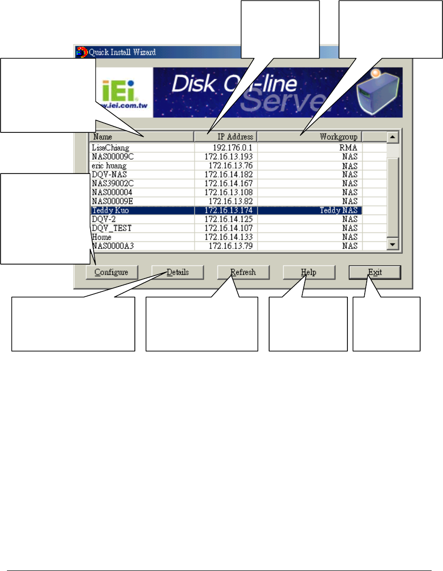
58
Appendix C Quick Install Wizard
Introduction
The Quick Install Wizard enables you to list the Disk On-line Servers within your local
network and display basic information such as server names, workgroups and IP addresses.
You may also set up the server name, date/time and basic network configuration of the Disk
On-line Server via this program.
Screenshot
Set up Server
N
ame, Date / Time
and basic network
configurations.
View detailed
information about the
selected server.
Re-search for Disk
Online Servers in
the network.
Display on-line
help for Quick
Install Wizard.
Configuratio
n complete;
exit program.
All Disk On-line
Servers can be
identified using a
unique server
name.
Indicates the IP
address of the
server.
Shows the Windows
workgroup joined by
the Disk On-line
Server.
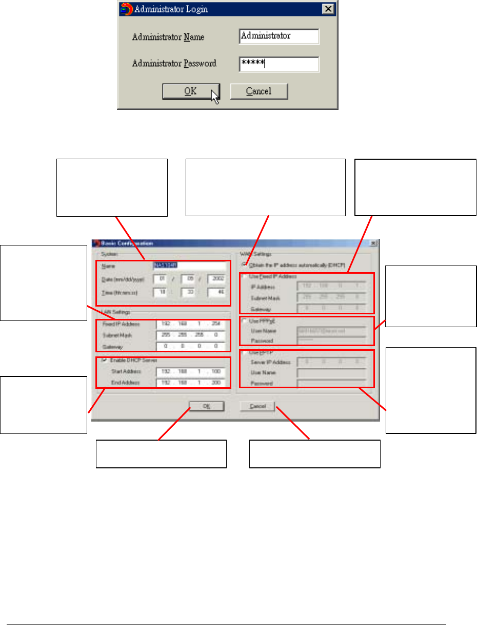
59
Operation Help
1. Set up your Disk On-line Server:
Select the Disk On-line Server that you want to configure, and then click on the
Configure button. An authentication window asking you to enter the administrator’s
password appears as shown below:
Click on OK after entering the password. If the name and password are correct, the
configuration window is displayed on the screen:
Change the settings and click on OK when done to complete the configuration setup.
Note:
1. After changing some settings, you may be asked to restart the Disk On-line Server.
2. If you want to set up detailed configuration, you need to enter the administration web
page of the Disk On-line Server via the browser.
For more configurations, check your browser under “System Administration”
Use DHCP protocol to obtain the WAN IP
address automatically. DHCP protocol is
commonly used in cable broadband service
or intranet.
Use a fixed IP address for
WAN port. You will need to
enter the IP address, subnet
mask and the gateway IP
address.
Click “Cancel” to exit and discard
changes.
When finished, click on “OK” to
confirm and exit.
If PPPoE is used to
connect to the
Internet, enter the user
name and password
p
rovided by you
r
ISP.
If PPTP is used to
connect to the
Internet, enter the
PPTP server IP
Address, user name
and password from
the ISP or network
administrator
Configure the DHCP
service to assign the
dynamic IP addresses
for your local
network.
Setup the name, date and
time of this Disk On-line
Server. You can input any
name you want except
special characters.
Change the LAN IP
address settings of
your Disk On-line
Server. If you are not
familiar with these
settings, please keep
them unchanged.
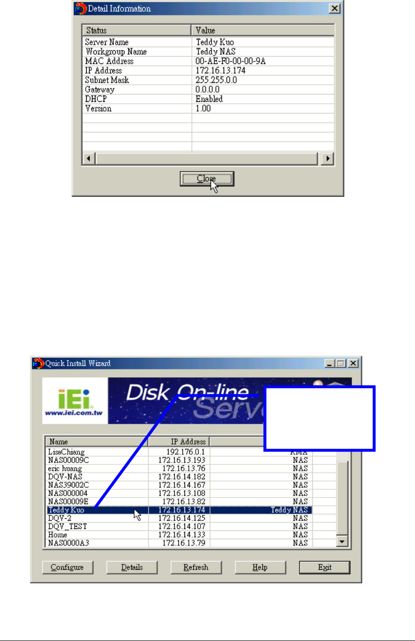
60
2. Viewing detailed information on the Disk On-line Server:
Choose the Disk On-line Server by highlighting it with the mouse, then click on
“Group Data” to display current settings and status as shown below:
3. To find information on other Disk On-line Servers in the same network:
Click on “Refresh” in the Toolbar to find information on other Disk On-line Servers in
the same network.
4. To display User Help File:
Click on “Help” display the Help file.
5. To enter the home page of the Disk On-line Server:
Double click on the name of the Disk On-line server to enter the web page for
advanced administration.
Double click on the
name of the Disk On-
line Server to enter the
web page for advanced
administration.
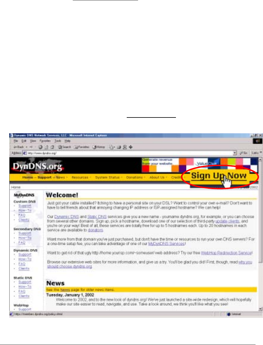
61
Appendix D
Registering a Dynamic Domain Name
Introduction
Your Disk On-line Server supports the DDNS service provided by DynDNS. You can go to
the web site of DynDNS (http://www.dyndns.org/) and register for a dynamic domain name.
Configure and activate the DDNS service, then the Internet users will be able to access your
Disk On-line Server via this dynamic domain name. When the ISP assigns a new WAN IP
address, the Disk On-line Server will update the new address to the DynDNS server
automatically.
Registration Procedure
Please follow below steps to register a dynamic domain name:
Note: This guide is for reference only. If there are any changes, please refer to the
instructions or documents on the web site.
a. Open the browser and connect to http://www.dyndns.org. Click on “Sign Up Now”
to begin the registration process.
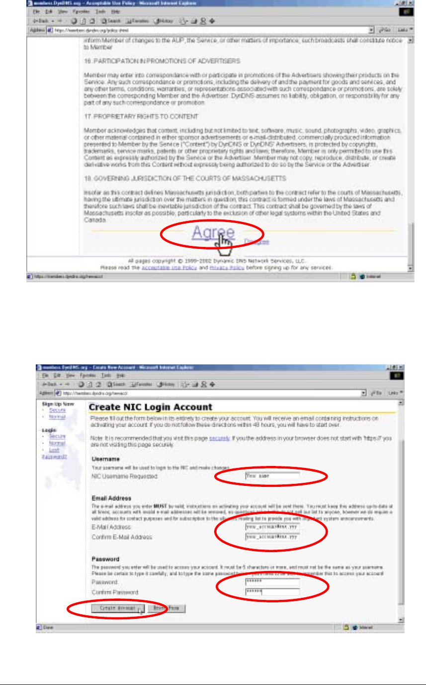
62
b. Click on “Agree” if you accept the service agreement.
c. Enter the username, email address and password to create a DDNS service account.
You will need to enter the same username and password in the Network Settings.
DDNS Service page of the Disk On-line Server system administration. Please verify
your email address to receive the confirmation message from the server. Then click
on “Create Account” to proceed.
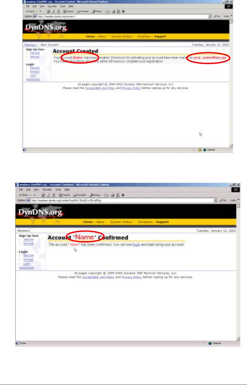
63
d. If below web page appears on the screen, your account has been successfully created
and a confirmation message has been sent to your -mail address. Please follow the
instructions in the e-mail to activate your account within 48 hours.
e. When you have finished the process of confirmation, a new screen will appear and
you can apply for your own dynamic domain name.