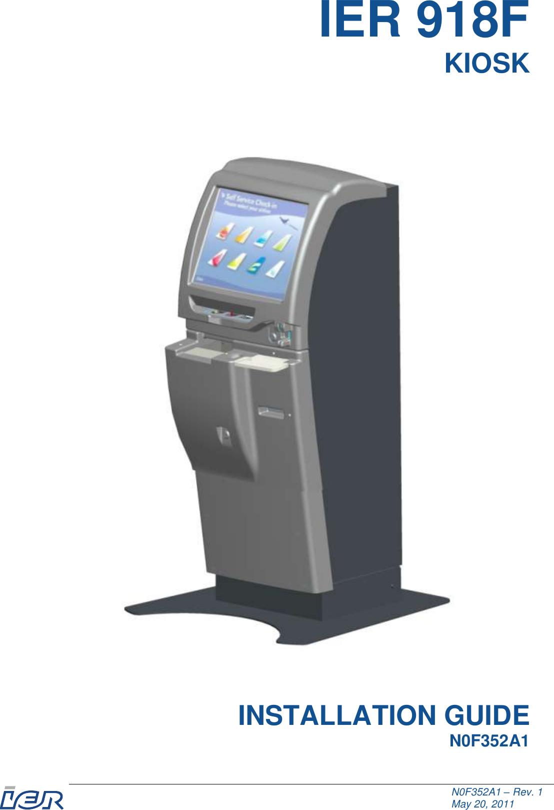
IER 918F-08 kiosk with RFID User Manual
IER kiosk with RFID
UserManual.wiki
>
IER
>
918F 08 User Manual
user manual
Navigation menu
Upload a User Manual
Namespaces
Wiki Guide
HTML
PDF
Info
Views
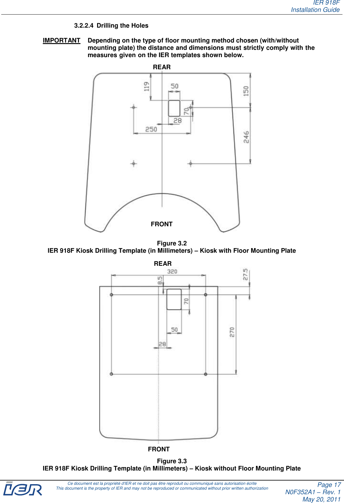
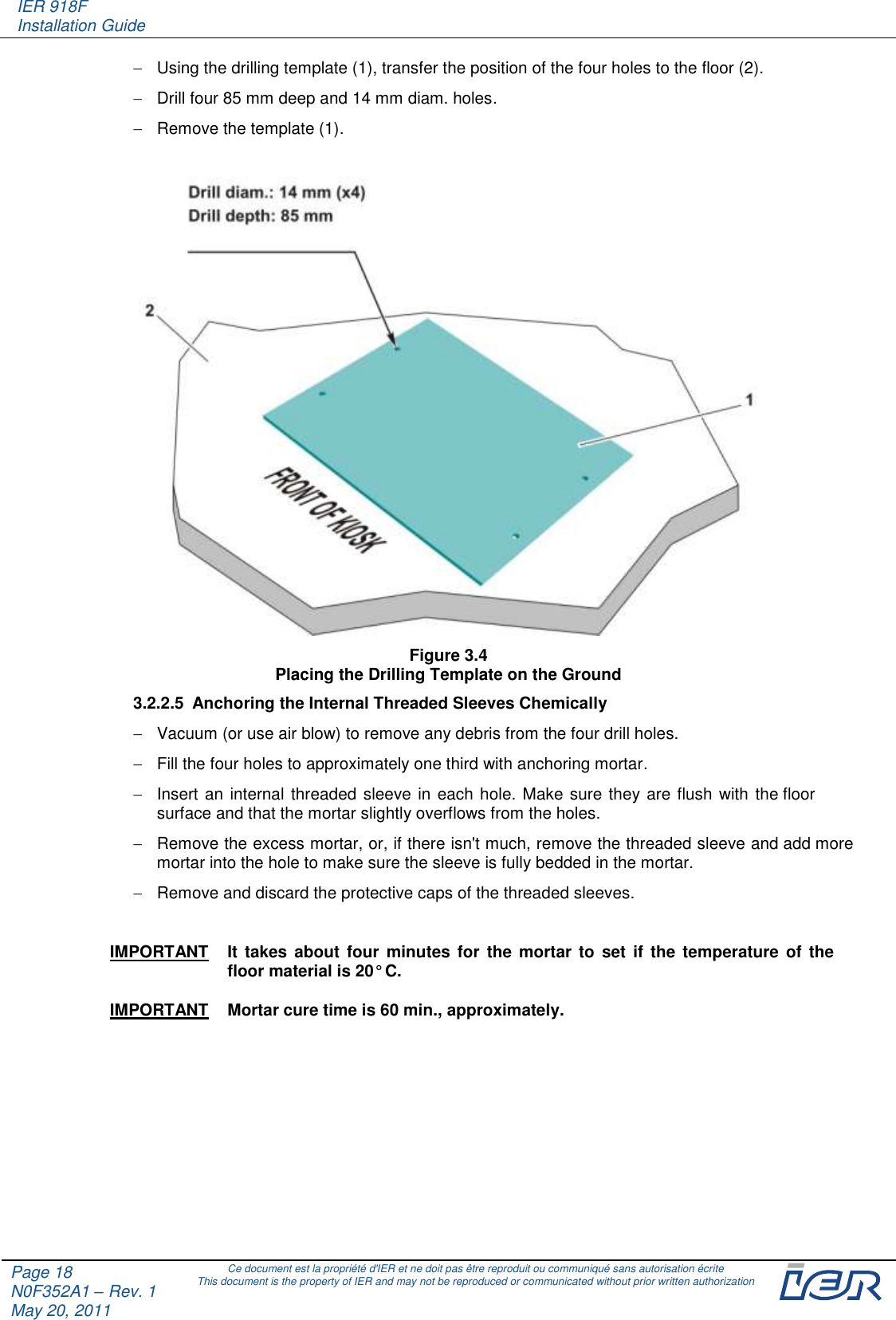
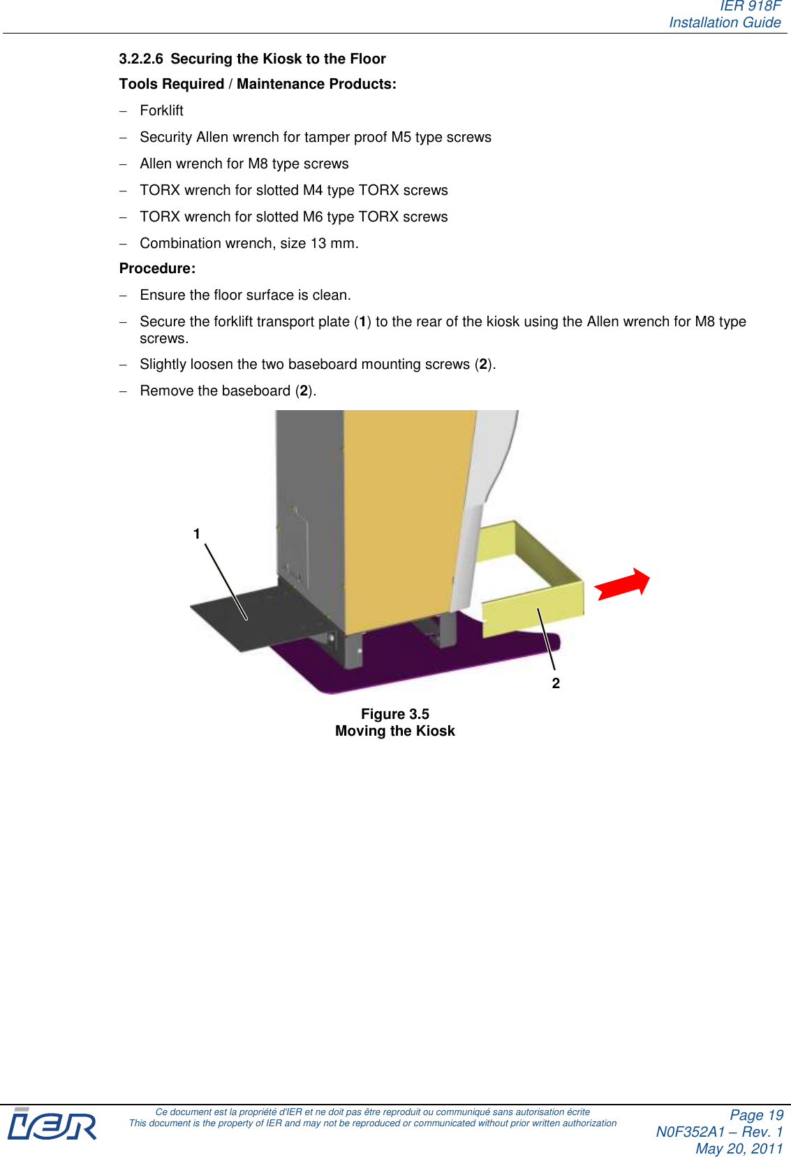
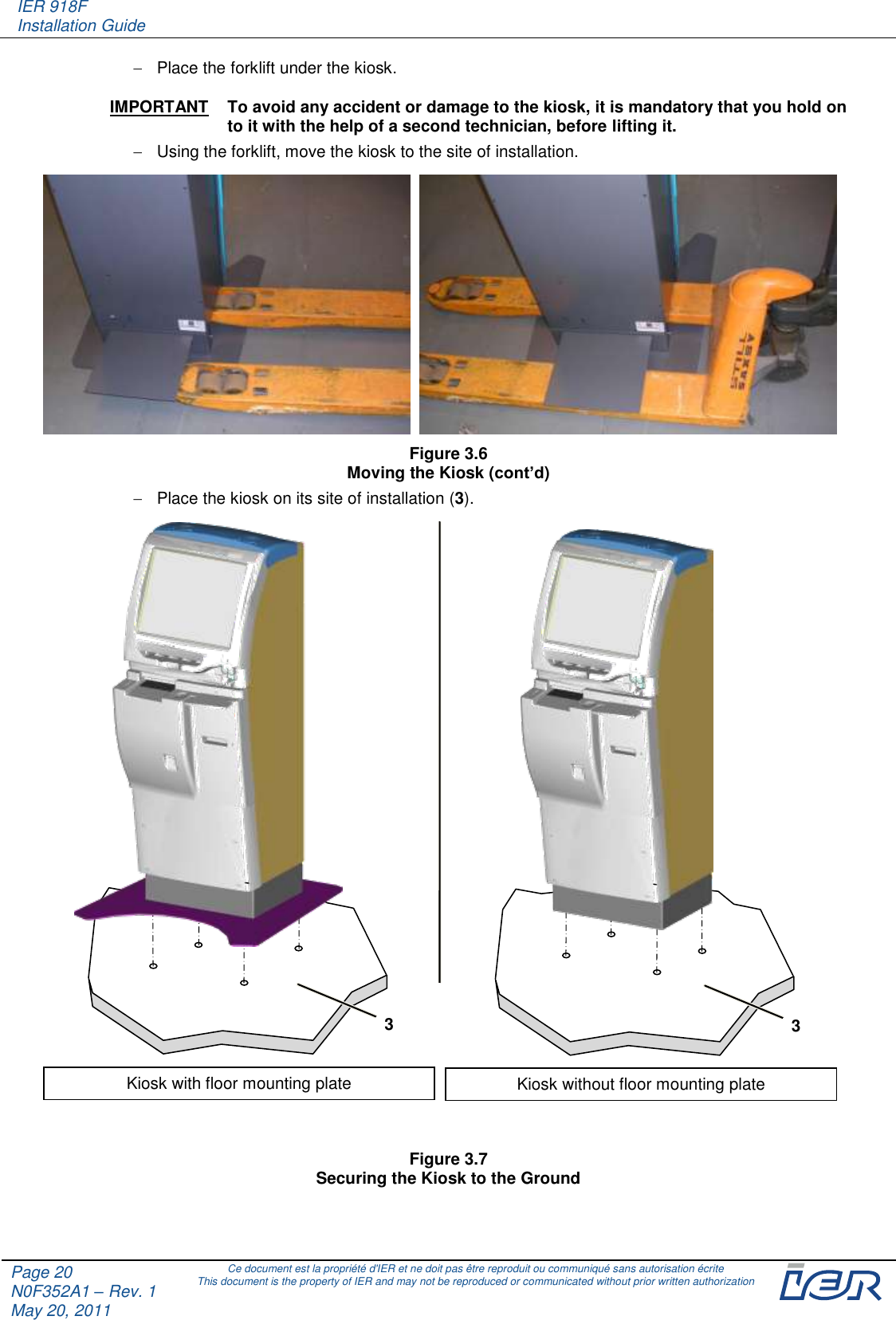
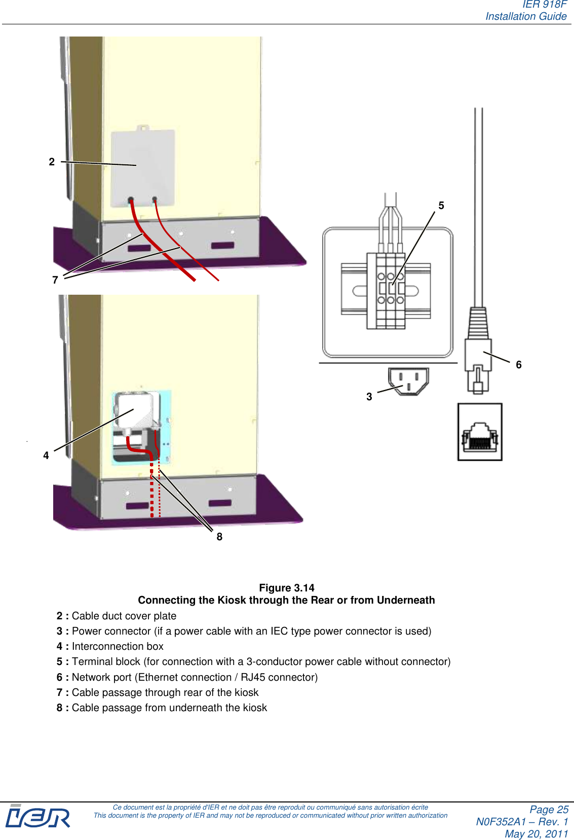
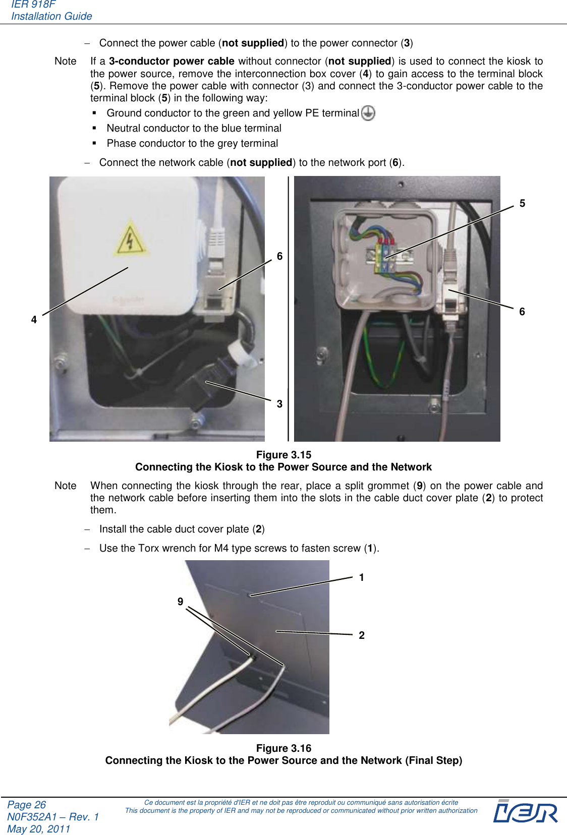
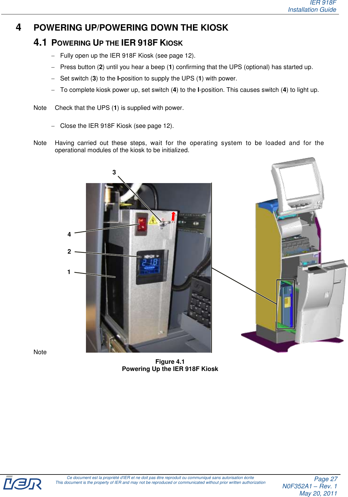
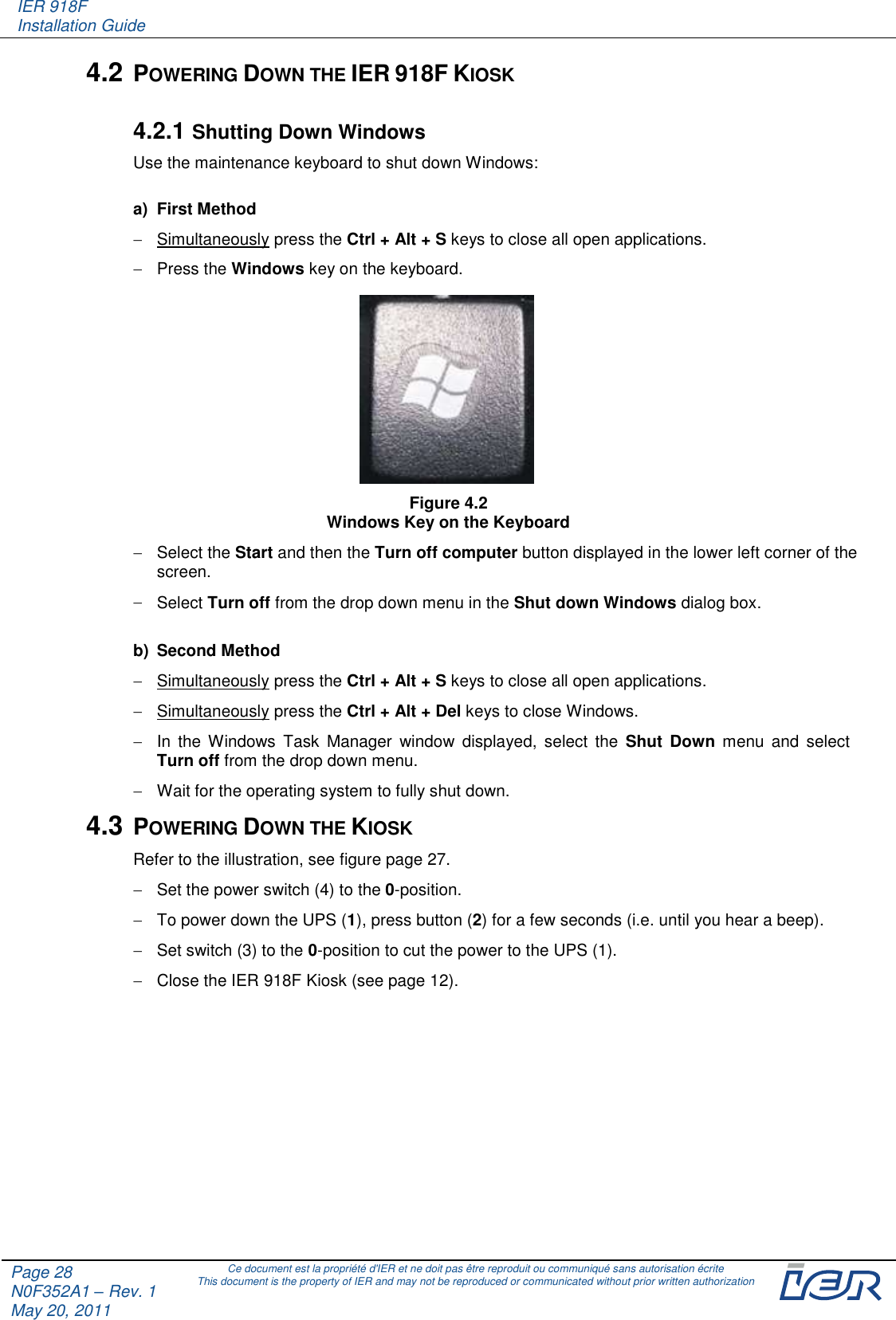
User Manual
Discussion / Help
Navigation