user manual
IER 918F
KIOSK
N0F352A1 – Rev. 1
May 20, 2011
INSTALLATION GUIDE
N0F352A1

IER 918F
Installation Guide
Page 2
N0F352A1 – Rev. 1
May 20, 2011
Ce document est la propriété d'IER et ne doit pas être reproduit ou communiqué sans autorisation écrite
This document is the property of IER and may not be reproduced or communicated without prior written authorization
IER SIEGE - HEADQUARTERS
IER S.A.
3, rue Salomon de Rothschild
92156 SURESNES CEDEX
France
Tel. +33 (0)1 41 38 60 00
Fax +33 (0)1 41 38 62 75
IER DANS LE MONDE - IER WORLDWIDE
CHINA
IER Shanghai
Kuen Yang Plaza #1101
798 Zhao Jia Bang Road
SHANGHAI 200030
P.R.C.
Phone: +86 (21) 6473 6792
Fax: +86 (21) 6473 6806
GERMANY
IER GmbH
Wilhelm-Heinichen-Ring 4
29227 CELLE
Phone: +49 (0) 5141/980 89 14
Fax: +49 (0) 5141/980 89 20
SINGAPORE
IER PTE Ltd
120 Lower Delta Road
#14-13/16 Cendex Centre
SINGAPORE 169208
Phone: +65 6276 6966
Fax: +65 6271 5563
UNITED STATES
IER Inc. Addison
16415 Addison Road
Suite 160
ADDISON, TEXAS, TX 75001
Phone: +1 (972) 991 2292
Fax: +1 (972) 991 1044
Toll free: 1-800 624 8538
IER Inc. Belton
1000 Industrial Park Road
BELTON, TX 76513
Phone: +1 (254) 933 5000
Fax: +1 (254) 933 5050
SPAIN
IER Impresoras Especializadas, S.L.
C/ Torre de Don Miguel, 23
E-28031 – MADRID
Phone: +34 91 535 89 75
Fax: +34 91 535 89 76
IER 918F
Installation Guide
Ce document est la propriété d'IER et ne doit pas être reproduit ou communiqué sans autorisation écrite
This document is the property of IER and may not be reproduced or communicated without prior written authorization
Page 3
N0F352A1 – Rev. 1
May 20, 2011
NOTICE
WARNING
THIS IER PRODUCT COMES WITH SEALED LEAD ACID BATTERIES (UPS) AND A LITHIUM
BATTERY (MAIN PCB). ANY KIND OF OPERATIONS ON THESE ELEMENTS MUST
EXCLUSIVELY BE CARRIED OUT BY MAINTENANCE PERSONNEL QUALIFIED BY IER.
MOREOVER, THESE BATTERIES MAY ONLY BE REPLACED BY IER APPROVED MODELS.
WARNING
DANGER OF EXPLOSION IF BATTERY IS INCORRECTLY REPLACED.
REPLACE ONLY WITH THE SAME OR EQUIVALENT TYPE RECOMMENDED BY THE
MANUFACTURER.
DISPOSE OF USED BATTERIES ACCORDING TO THE MANUFACTURER’S INSTRUCTIONS.
The United States Federal Communications Commission (in 47 CFR 15.105) has specified that the following notice be
brought to the attention of users of this product.
NOTE: This equipment has been tested and found to comply with the limits for a Class B digital device, pursuant to Part 15
of the FCC Rules. These limits are designed to provide reasonable protection against harmful interference in a residential
installation. This equipment generates, uses and can radiate radio frequency energy and, if not installed and used in
accordance with the instructions, may cause harmful interference to radio communications. However, there is no guarantee
that interference will not occur in a particular installation.
If this equipment does cause harmful interference to radio or television reception, which can be determined by turning the
equipment off and on, the user is encouraged to try to correct the interference by one or more of the following measures:
Reorient or relocate the receiving antenna
Increase the separation between the equipment and receiver
Connect the equipment into an outlet on a circuit different from that to which the receiver is connected
Consult the dealer or an experienced radio/TV technician for help.
In accordance with FCC requirements, changes or modifications not expressly approved by IER could void the user's
authority to operate this product.
Use of a shielded cable is required to comply within Class B limits of Part 15 of FCC Rules.
The AC line power connector must at all times be accessible, as it serves as the disconnecting device.
WARNING
THIS APPLIANCE MUST BE GROUNDED.
THIS PRODUCT MUST EXCLUSIVELY BE CONNECTED TO AN ELECTRICAL CIRCUIT THAT
IS:
PROVIDED WITH A GROUND FAULT CIRCUIT INTERRUPTER (GFCI) COMPLYING WITH
IEC 364 AND NFC15-100 REGULATIONS, AND
CONFORMING WITH THE VOLTAGE CHARACTERISTICS SPECIFIED BY THE NF EN
50160 STANDARD.
The cover(s), door(s) and/or drawer(s) of this product is (are) intended for occasional use and must be normally closed.
This document contains proprietary information of IER. It may not be reproduced or communicated
without prior written authorization of IER. It is intended solely for the use of the product described
herein, to the exclusion of any other usage.
It is provided as is, for information purposes only, without any warranty of any kind, including any
warranty of fitness or a particular purpose, and may be modified by IER at any time.
The warranty shall be null and void in case of use of any spare part, special tool or consumable
not expressly approved in writing by IER and in the event of attempted repair or servicing of the
machines by persons lacking the requisite technical qualifications.
IER 918F
Installation Guide
Page 4
N0F352A1 – Rev. 1
May 20, 2011
Ce document est la propriété d'IER et ne doit pas être reproduit ou communiqué sans autorisation écrite
This document is the property of IER and may not be reproduced or communicated without prior written authorization
NORWAY – SWEDEN – FINLAND: Apparaten skall anslutas till jordat uttag när den ansluts till ett nätverk.
The equipment complies with R&TTE directive 1999/5/EC of the European Parliament and of the council of 9 March 1999.
The equipment may be fitted with RFID contactless readers working in the frequency band 13.553-13.567MHz for inductive application.
The equipment may be fitted with RFID UHF reader working in the frequency band 869.4-869.65MHz for non specific short range
device.
The comprehensive EC declaration of conformity is available on request from IER Quality Department.
In compliance with the European Directive 2002/96/CE relative to the management of Waste Electrical and Electronic Equipment
(WEEE) implemented as of August 13, 2005, this product may not be disposed of with regular household waste. All products concerned
by this directive are marked with the above symbol.
The end owner of this product is responsible for either:
Transferring the product to an authorized treatment facility where the product components, recognized to present a hazard to
the environment and/or public health, will be recycled and recovered properly, or
Consulting with the manufacturer for appropriate product waste management according to the terms of the manufacturer.
The information and specifications contained in this document are subject to change without prior notice.
Translated from French - IER Documentation Department
Marking and European Economic Area

IER 918F
Installation Guide
Ce document est la propriété d'IER et ne doit pas être reproduit ou communiqué sans autorisation écrite
This document is the property of IER and may not be reproduced or communicated without prior written authorization
Page 5
N0F352A1 – Rev. 1
May 20, 2011
TABLE OF CONTENTS
1 Unpacking the IER 918F Kiosk ...................................................................................................................... 6
1.1 Contents of the Shipping Container ....................................................................................................... 6
1.2 Unpacking .............................................................................................................................................. 6
1.3 Dimensions and Weight ......................................................................................................................... 9
1.3.1 IER 918F Kiosk without OCR Passport Swipe Reader ..................................................................... 9
1.3.2 IER 918F Kiosk with OCR Passport Swipe Reader .......................................................................... 9
2 IER 918F Kiosk Description.......................................................................................................................... 10
2.1 Opening/Closing the IER 918F Kiosk .................................................................................................. 12
2.1.1 Opening the Upper Part of the IER 918F Kiosk ............................................................................... 12
2.1.2 Closing the Upper Part of the IER 918F Kiosk ................................................................................ 12
2.1.3 Opening the Lower Part of the IER 918F Kiosk ............................................................................... 13
2.1.4 Closing the Lower Part of the IER 918F Kiosk ................................................................................ 13
3 Kiosk Installation ........................................................................................................................................... 14
3.1 Environmental Conditions and Power Supply Requirements .............................................................. 14
3.1.1 Environmental Conditions ................................................................................................................ 14
3.1.2 Electrical Characteristics.................................................................................................................. 14
3.2 Installing the IER 918F Kiosk .............................................................................................................. 16
3.2.1 Preliminary Information .................................................................................................................... 16
3.2.2 Kiosk Installation with Floor Anchoring Procedure .......................................................................... 16
3.2.3 Installation Procedure for Kiosks not Anchored to the Floor ........................................................... 24
3.2.4 Connecting the Kiosk ....................................................................................................................... 24
4 Powering Up/Powering Down the Kiosk ....................................................................................................... 27
4.1 Powering Up the IER 918F Kiosk ........................................................................................................ 27
4.2 Powering Down the IER 918F Kiosk.................................................................................................... 28
4.2.1 Shutting Down Windows .................................................................................................................. 28
4.3 Powering Down the Kiosk .................................................................................................................... 28
5 Loading the Consumables ............................................................................................................................ 29
5.1 General Purpose Thermal Printer (GPP) ............................................................................................. 29
5.1.1 Media Loading Procedure ................................................................................................................ 29
5.2 Bag Tag Printer (OPTION) .................................................................................................................. 32
5.2.1 Media Loading Procedure ................................................................................................................ 32
5.2.2 Adjusting the Width of the Paper Path ............................................................................................. 34
6 TEST ............................................................................................................................................................. 36
6.1 Testing the Kiosk Functions - IER Test Utility .................................................................................... 36

IER 918F
Installation Guide
Page 6
N0F352A1 – Rev. 1
May 20, 2011
Ce document est la propriété d'IER et ne doit pas être reproduit ou communiqué sans autorisation écrite
This document is the property of IER and may not be reproduced or communicated without prior written authorization
1 UNPACKING THE IER 918F KIOSK
Tools Required / Maintenance Products:
Utility knife
Needle nose pliers
Phillips screwdriver
1.1 CONTENTS OF THE SHIPPING CONTAINER
The IER 918F Kiosk is shipped in one single container. The box contains the following:
IER 918F Kiosk
Two sets of identical keys:
One set of two keys to open the upper part of the kiosk
One set of two keys to open the lower part of the kiosk
Two split grommets to protect the power cable and the Ethernet cable
One forklift transport plate (optional)
The box also contains one or several pieces of kiosk documentation:
Operation Guide
Installation Guide
Note These documents are available for download from our website: www.ier.fr.
1.2 UNPACKING
Note Have handy the tools necessary to unpack the IER 918F Kiosk (see above Tools Required
list).
Procedure:
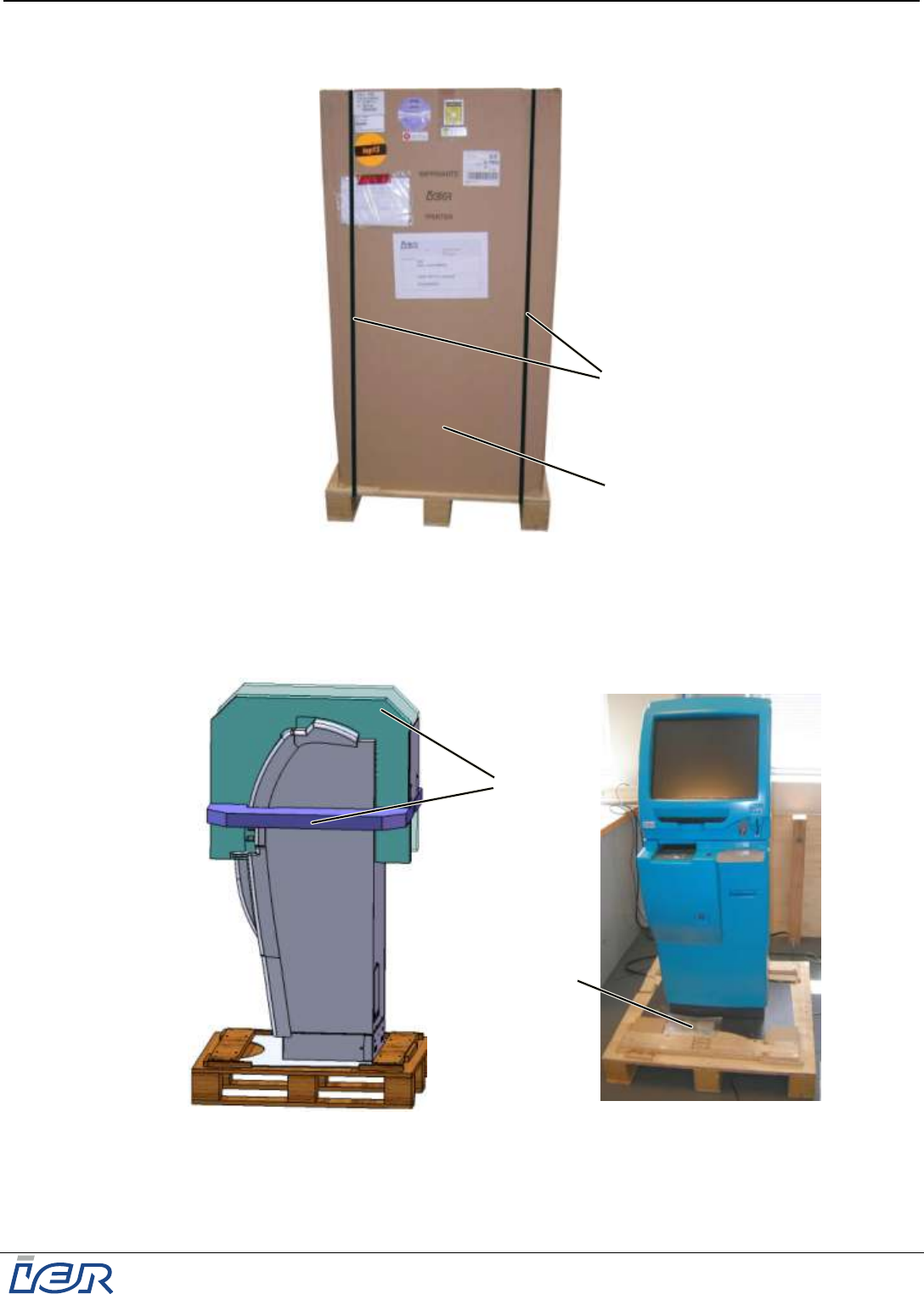
Check the state of the box and that of the shipping and handling monitors (1) and (2)
(SHOCKWATCH and TILTWATCH indicators).
Figure 1.1
State of the Shipping Container and the Shipping Monitors
IMPORTANT If one or both of the indicators (1) and/or (2) has (have) turned red (NOK),
follow the instructions indicated on the label (3).
1
3
2
3
NOK
NOK
IER 918F
Installation Guide
Ce document est la propriété d'IER et ne doit pas être reproduit ou communiqué sans autorisation écrite
This document is the property of IER and may not be reproduced or communicated without prior written authorization
Page 7
N0F352A1 – Rev. 1
May 20, 2011
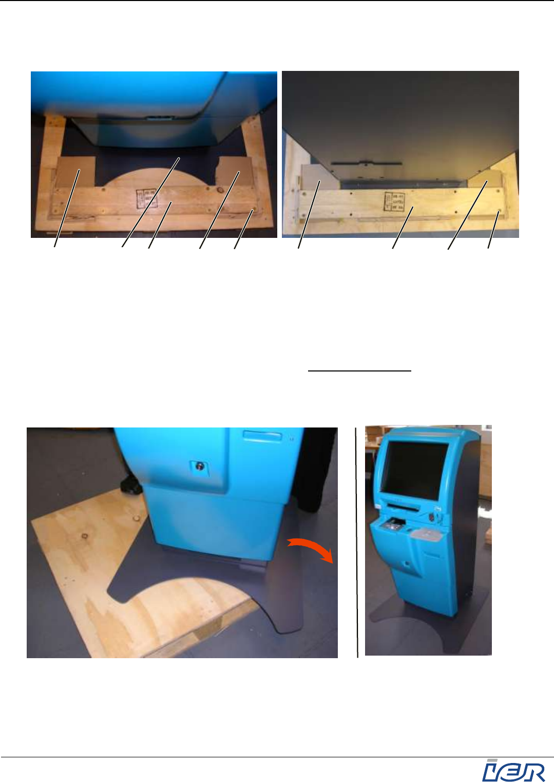
Use the utility knife to cut the two plastic straps (4) and remove them.
Remove the shipping container (5) and set it aside.
Figure 1.2
Unpacking the Kiosk - Step 1
Remove the two pieces of polyester padding (6).
Remove the plastic bag (7) containing the documentation, the keys, the split grommets and
the roll media hanger.
Figure 1.3
Unpacking the Kiosk - Step 2
Using the Phillips screwdriver, unscrew and remove the six screws (8) to be able to remove
board (9) securing the front of the kiosk.
6
7
5
4
IER 918F
Installation Guide
Page 8
N0F352A1 – Rev. 1
May 20, 2011
Ce document est la propriété d'IER et ne doit pas être reproduit ou communiqué sans autorisation écrite
This document is the property of IER and may not be reproduced or communicated without prior written authorization
Using the Phillips screwdriver, unscrew and remove the four screws (10) to be able to remove
board (11) securing the rear of the kiosk.
Remove the cardboard protections (12) at the front and at the rear of the floor mounting
plate (13).
Figure 1.4
Unpacking the Kiosk - Step 3
Use the needle nose pliers to remove the transport blockers holding the kiosk in place.
Note Having removed the transport blockers, drive the staples remaining on the pallet all the way in or
remove them completely. This makes it possible to slide the kiosk off the pallet without snagging.
Cautiously push the kiosk in successive steps sidewise off the pallet (see figure below).
Note Having removed the kiosk from the pallet, we strongly recommend you move the kiosk with
the help of a second technician.
Note Never tilt the kiosk towards the front as the front of the mounting plate could get
damaged.
Figure 1.5
Unpacking the Kiosk - Final Step
The unpacking procedure being completed, IER 918F Kiosk is now ready to be installed.
8
10
9
11
12
12
13
12
12
IER 918F
Installation Guide
Ce document est la propriété d'IER et ne doit pas être reproduit ou communiqué sans autorisation écrite
This document is the property of IER and may not be reproduced or communicated without prior written authorization
Page 9
N0F352A1 – Rev. 1
May 20, 2011
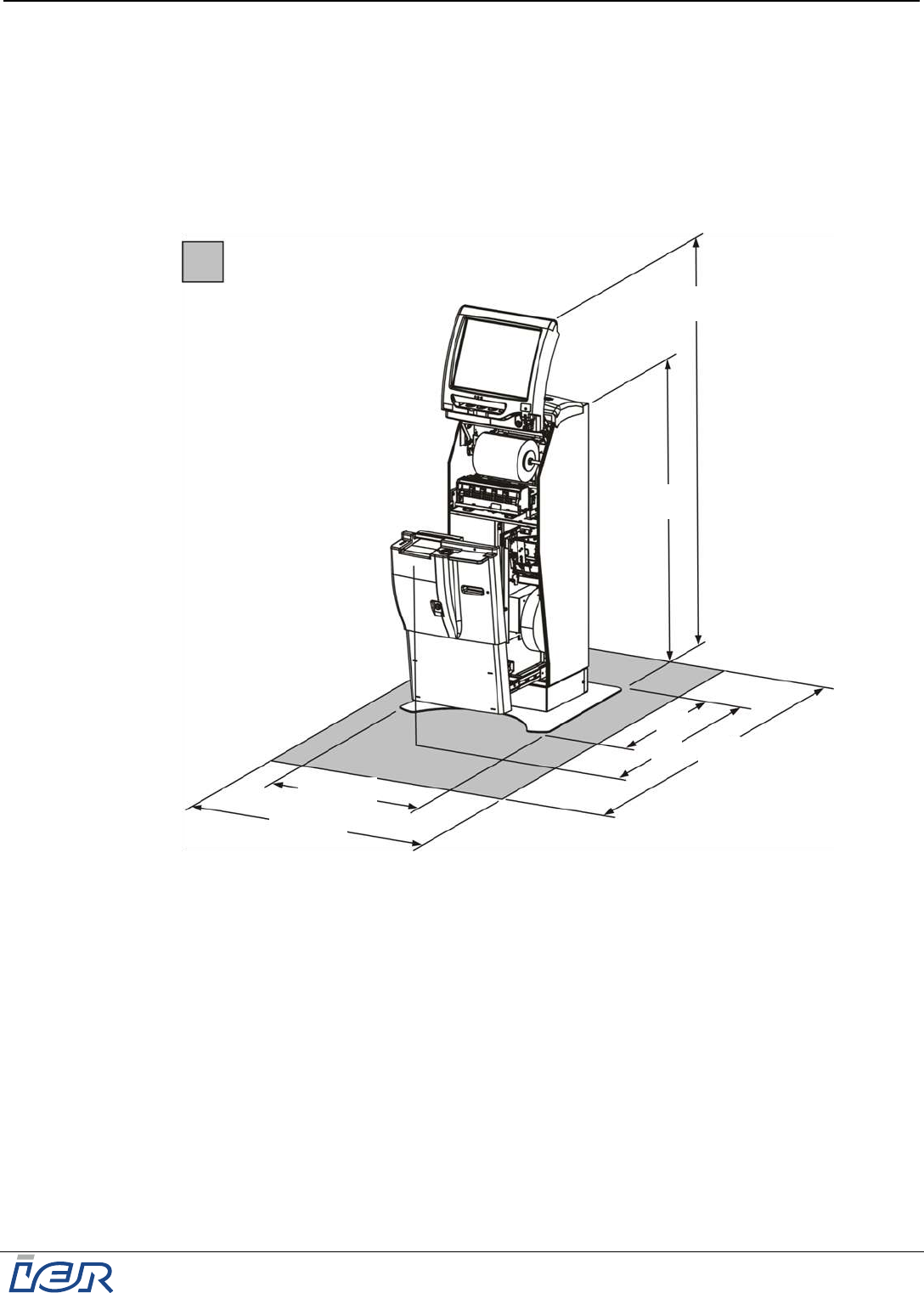
1.3 DIMENSIONS AND WEIGHT
1.3.1 IER 918F Kiosk without OCR Passport Swipe Reader
Height ............................................................................................................. 1239 mm (48.78 in)
Depth ................................................................................................................ 695 mm (27.36 in)
Width ................................................................................................................ 680 mm (26.77 in)
Weight .................................................................................................................132 Kg (291 lbs)
Figure 1.6
Dimensions of the IER 918F Kiosk without OCR Passport Swipe Reader
1.3.2 IER 918F Kiosk with OCR Passport Swipe Reader
Height ............................................................................................................. 1261 mm (49.65 in)
Depth ................................................................................................................ 695 mm (27.36 in)
Width ................................................................................................................ 680 mm (26.77 in)
Weight .......................................................................................................... 132.5 Kg (292.1 lbs)
Dimensions in Millimeters
1600
680
840
Recommended clearance for
kiosk operation/kiosk
maintenance
1239
695
968
1490

IER 918F
Installation Guide
Page 10
N0F352A1 – Rev. 1
May 20, 2011
Ce document est la propriété d'IER et ne doit pas être reproduit ou communiqué sans autorisation écrite
This document is the property of IER and may not be reproduced or communicated without prior written authorization
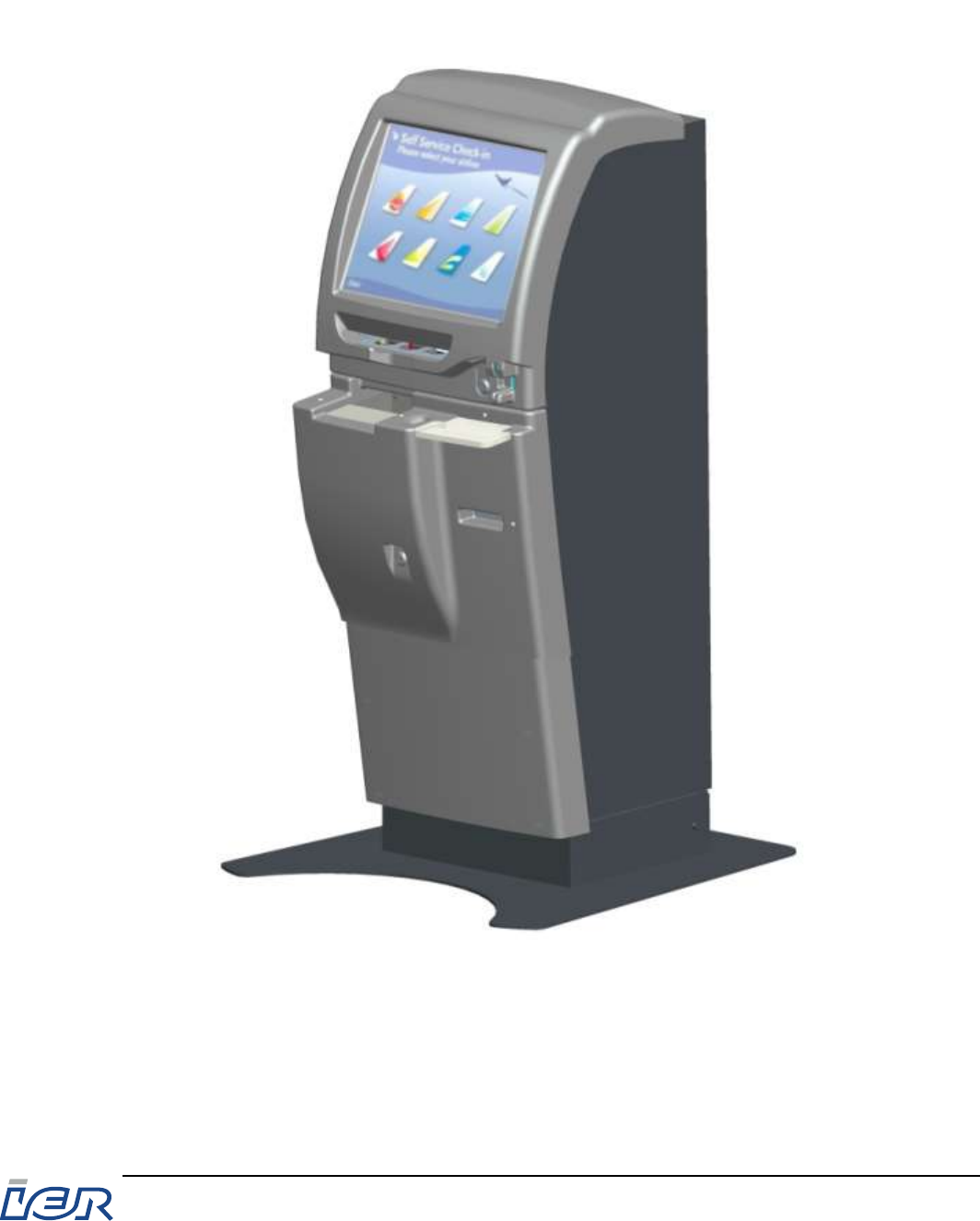
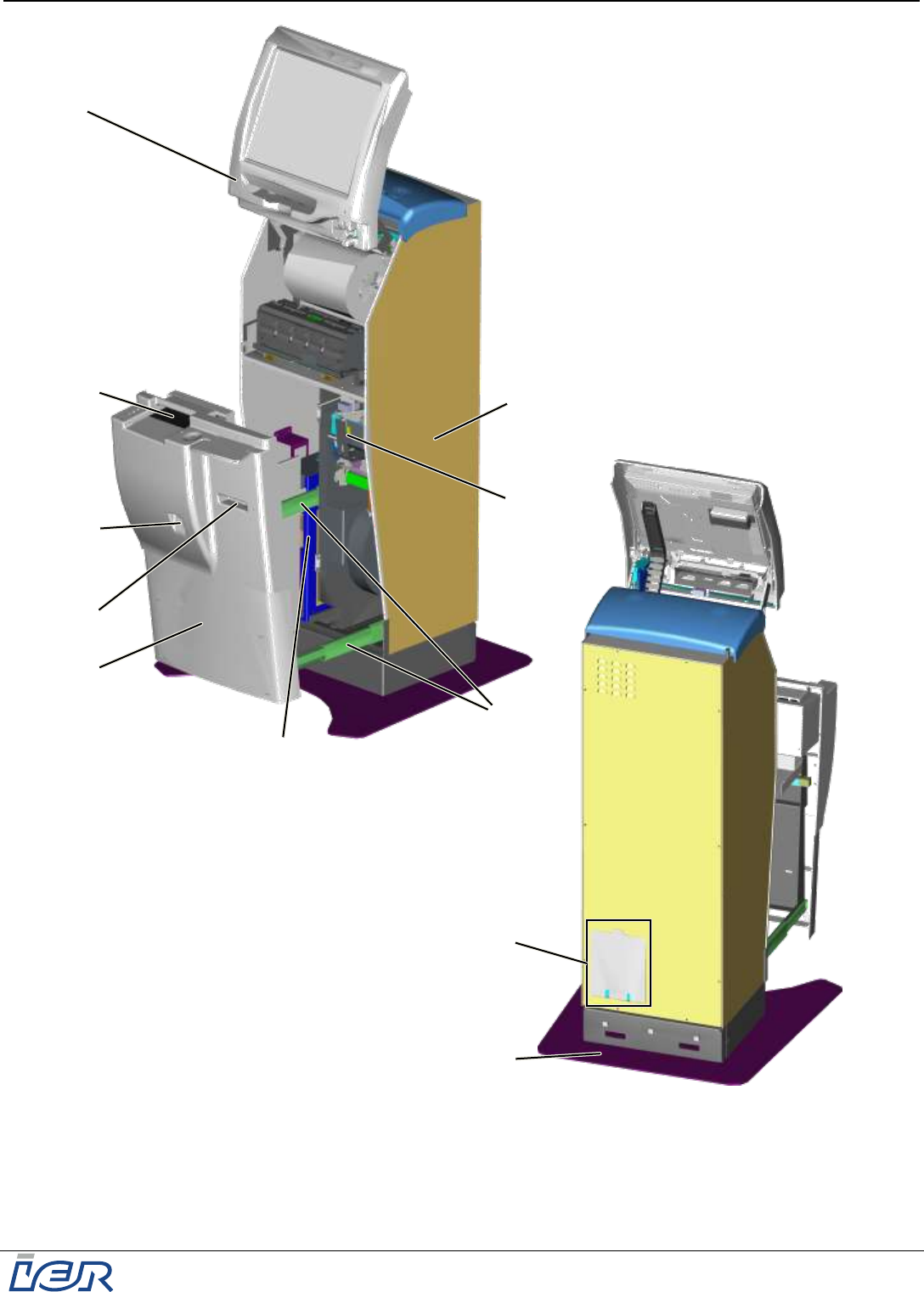
2 IER 918F KIOSK DESCRIPTION
The IER 918F Kiosk is essentially made up of a display assembly (1) in its upper part and a drawer
(4) in its lower part.
The housing (2) is at the same time the frame of the IER 918F Kiosk.
The drawer (4) in the lower part of the housing (2) slides on three telescopic rails (3).
The kiosk drawer (4) face plate can accommodate the following elements:
Full page passport reader (5) (option)
Bag Tag printer output bezel (6) (option)
Drawer (4) lock (9)
The lower part of the housing (2) can also accommodate the following elements:
Bag Tag printer (7) (option)
Power supply unit with the main power switch.
In addition, this unit can be provided with an Uninterruptible Power Supply (UPS) (8) (option).
At the rear, the kiosk features the following elements:
Cable duct cover plate (10) giving access to the following:
Power connector to connect the kiosk to the power source with a power cable (not supplied)
Interconnection box to connect a 3-conductor power cable without connector (3-conductor
power cable not supplied)
Ethernet port for network connection
Moreover, the kiosk is provided with a standard floor mounting plate (11) ensuring kiosk stability.
IER 918F
Installation Guide
Ce document est la propriété d'IER et ne doit pas être reproduit ou communiqué sans autorisation écrite
This document is the property of IER and may not be reproduced or communicated without prior written authorization
Page 11
N0F352A1 – Rev. 1
May 20, 2011
Figure 2.1
IER 918F Kiosk – Front View, Rear View
3
4
2
5
9
6
8
10
11
7
1
IER 918F
Installation Guide
Page 12
N0F352A1 – Rev. 1
May 20, 2011
Ce document est la propriété d'IER et ne doit pas être reproduit ou communiqué sans autorisation écrite
This document is the property of IER and may not be reproduced or communicated without prior written authorization
2.1 OPENING/CLOSING THE IER 918F KIOSK
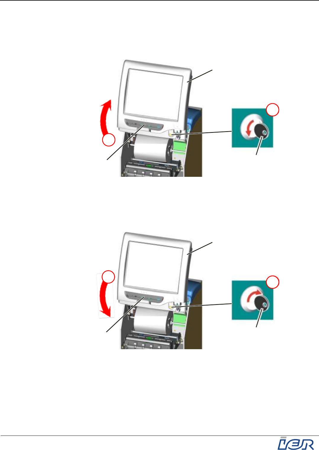
2.1.1 Opening the Upper Part of the IER 918F Kiosk
Step 1: Turn key (2) one quarter turn to the left to unlock the display assembly (1).
Step 2: Reach into the output slot (3) of the display assembly (1) and swing it up.
Figure 2.2
Opening the Upper Part of the Kiosk
2.1.2 Closing the Upper Part of the IER 918F Kiosk
Step 1: Reach into the output slot (3) of the display assembly (1) and swing it down.
Step 2: Turn key (2) one quarter turn to the right to lock the display assembly (1).
Figure 2.3
Closing the Upper Part of the Kiosk
2
2
1
1
3
2
1
1
3
2
IER 918F
Installation Guide
Ce document est la propriété d'IER et ne doit pas être reproduit ou communiqué sans autorisation écrite
This document is the property of IER and may not be reproduced or communicated without prior written authorization
Page 13
N0F352A1 – Rev. 1
May 20, 2011
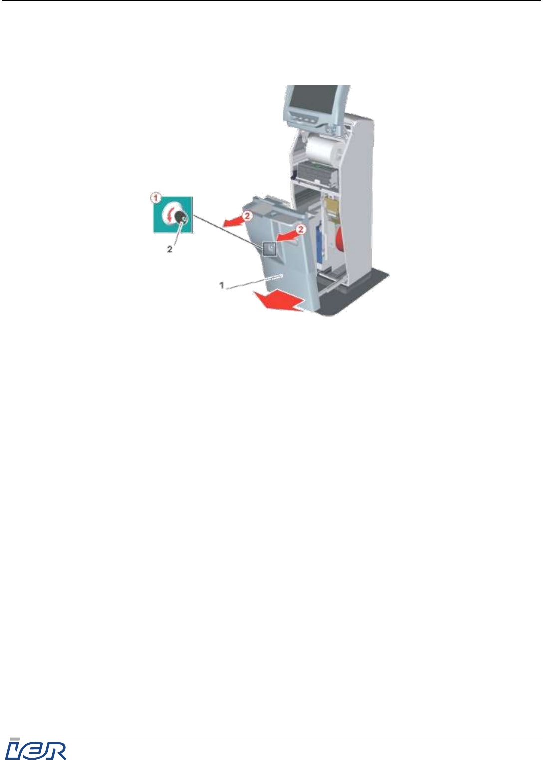
2.1.3 Opening the Lower Part of the IER 918F Kiosk
Turn key (2) one quarter turn to the left to unlock the kiosk drawer (1) and grasp the
drawer face plate (1) on one side.
Pull it to the stop (i.e. to the drawer open position).
Figure 2.4
Opening the Lower Part of the Kiosk
2.1.4 Closing the Lower Part of the IER 918F Kiosk
Refer to figure 2.4.
Grasp the drawer face plate (1) on each side and push it fully home.
Note: When closing the drawer (1), make sure you hear a click, confirming that it is properly closed and
locked.

IER 918F
Installation Guide
Page 14
N0F352A1 – Rev. 1
May 20, 2011
Ce document est la propriété d'IER et ne doit pas être reproduit ou communiqué sans autorisation écrite
This document is the property of IER and may not be reproduced or communicated without prior written authorization
3 KIOSK INSTALLATION
3.1 ENVIRONMENTAL CONDITIONS AND POWER SUPPLY REQUIREMENTS
IMPORTANT The site for kiosk installation must be chosen according to the operational
and dimensional requirements listed in the present document (see page 9).
IMPORTANT Two technicians are required for moving and installing the kiosk.
3.1.1 Environmental Conditions
Operating temperature .......... ...........................................................+5°C to 35°C (41°F to 95°F)
Relative humidity ......... ..........................................................20% to 80%, without condensation
Operating environment ......................................................................... fully enclosed area (such
.................................................................... as airport lobby, railway station, travel agency, etc.)
3.1.2 Electrical Characteristics
Power supply voltage (accepted voltage ranges)
EUROPE 230 VAC / 50 Hz / 1.8 A
USA 120 VAC / 60 Hz / 3.5 A
Power
when idle 115 W
when printing 140 W
Consumption (BTU - British Thermal Unit)
when idle 392
when printing 477
IER 918F
Installation Guide
Ce document est la propriété d'IER et ne doit pas être reproduit ou communiqué sans autorisation écrite
This document is the property of IER and may not be reproduced or communicated without prior written authorization
Page 15
N0F352A1 – Rev. 1
May 20, 2011
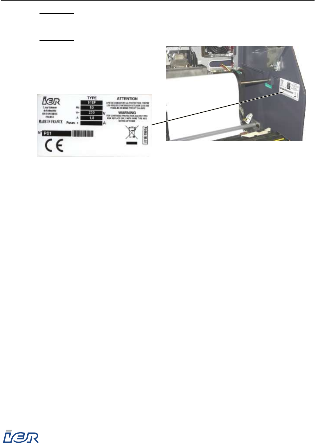
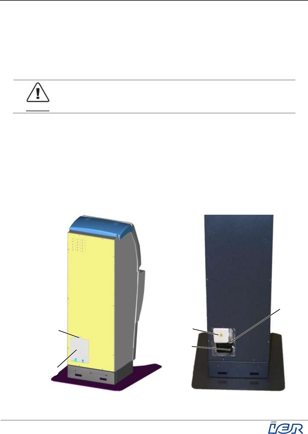
IMPORTANT The company ID plate (1) specifies the electrical characteristics of the kiosk
depending on its configuration. It also indicates the serial number and the
standards the kiosk complies with.
IMPORTANT The company ID plate (1) is located inside the kiosk, in its upper part.
Figure 3.1
Locating the IER 918F Kiosk Company ID Plate

IER 918F
Installation Guide
Page 16
N0F352A1 – Rev. 1
May 20, 2011
Ce document est la propriété d'IER et ne doit pas être reproduit ou communiqué sans autorisation écrite
This document is the property of IER and may not be reproduced or communicated without prior written authorization
3.2 INSTALLING THE IER 918F KIOSK
3.2.1 Preliminary Information
IER 918F Kiosk installation does not imply any particular difficulties. The procedure
mainly consists of the following steps:
Placing the kiosk in the assigned location.
Connecting the kiosk to the power source and the communications network.
Kiosk stability is achieved through one of the following methods:
Bolting the kiosk to the floor and simultaneous use of the floor mounting plate.
Bolting the kiosk to the floor without the floor mounting plate, but with internal threaded
sleeves, chemically anchored to the floor.
Use of the floor mounting plate alone without anchoring the kiosk to the floor.
IMPORTANT If the IER 918F Kiosk is not to be bolted to the floor, it is MANDATORY to install
it with the IER floor mounting plate.
IMPORTANT When choosing the site of installation, make sure there will be enough space
around the kiosk to use and operate it, to service it (opening of the drawer and
of the display assembly) and for ventilation.
Note The method used to secure the IER 918F Kiosk to the ground must be adapted to the
environmental conditions and to the type and quality of floor the kiosk is to be secured to (see
kiosk installation prerequisites). Solely certified civil engineers are qualified to carry out the
floor anchoring operations for the IER 918F Kiosk.
IMPORTANT IER STRONGLY RECOMMENDS THAT THE IER 918F KIOSK BE SECURED TO
THE GROUND BEFORE IT IS BEING OPERATED.
IER shall not be liable for any damage(s), any incident(s) and/or accident(s)
due to the fact that the kiosk has not been secured in strict compliance with
the instructions of the civil engineer.
3.2.2 Kiosk Installation with Floor Anchoring Procedure
3.2.2.1 Kiosk Dimensions
The final location of the kiosk must be carefully chosen with regard to kiosk dimensions and
the functional requirements listed in the present guide (see page 9).
3.2.2.2 Recommendations
IMPORTANT When choosing the site, make sure there is enough space around the kiosk to
operate it, to perform maintenance and to ensure proper ventilation.
IMPORTANT Should the floor be heated, ensure that kiosk anchoring does not interfere
with the tubing, the ducts, the electric network or any other underfloor
equipment.
3.2.2.3 Required Material (list given for informative purposes, has to be adapted to
the nature of the floor)
1 power drill and diam. 14 mm drill bit
4 internal threaded sleeves, P/N HIT-IC M8
Injectable urethane methacrylate mortar, P/N HILTI HIT-MM PLUS/330 ml (pack of 10
cartridges)
1 manual dispenser, P/N HILTI MD 2000
4 CHc M8x65 bolts, min.
4 large L8 type washers
IER 918F
Installation Guide
Ce document est la propriété d'IER et ne doit pas être reproduit ou communiqué sans autorisation écrite
This document is the property of IER and may not be reproduced or communicated without prior written authorization
Page 17
N0F352A1 – Rev. 1
May 20, 2011
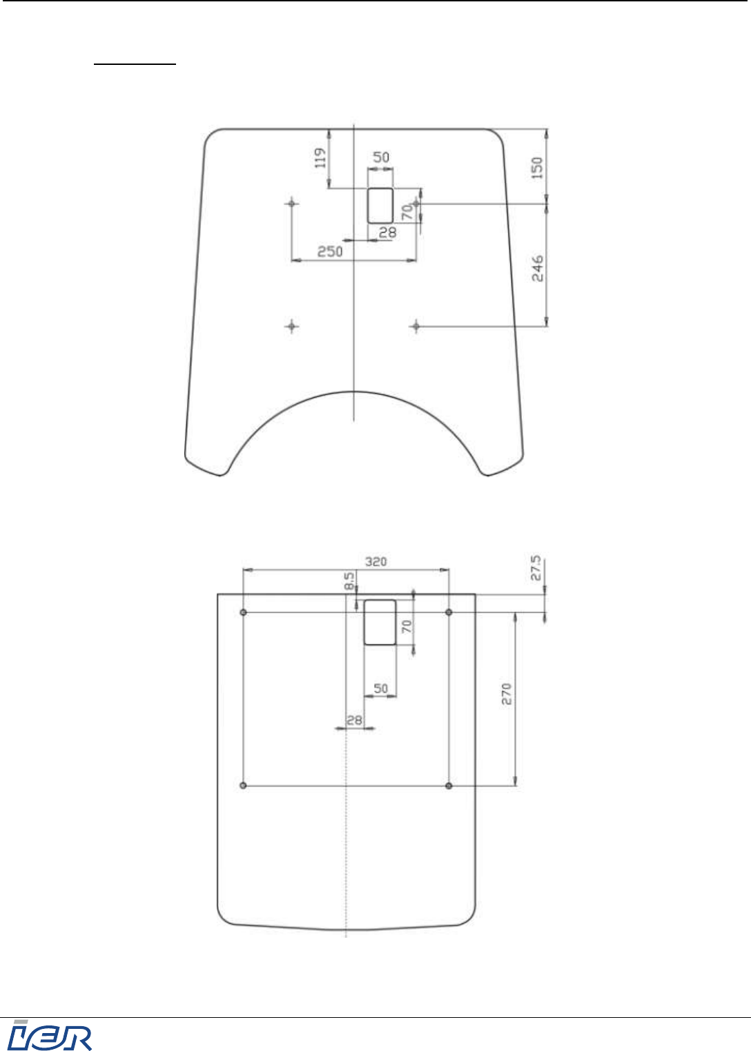
3.2.2.4 Drilling the Holes
IMPORTANT Depending on the type of floor mounting method chosen (with/without
mounting plate) the distance and dimensions must strictly comply with the
measures given on the IER templates shown below.
Figure 3.2
IER 918F Kiosk Drilling Template (in Millimeters) – Kiosk with Floor Mounting Plate
Figure 3.3
IER 918F Kiosk Drilling Template (in Millimeters) – Kiosk without Floor Mounting Plate
FRONT
REAR
FRONT
REAR
IER 918F
Installation Guide
Page 18
N0F352A1 – Rev. 1
May 20, 2011
Ce document est la propriété d'IER et ne doit pas être reproduit ou communiqué sans autorisation écrite
This document is the property of IER and may not be reproduced or communicated without prior written authorization
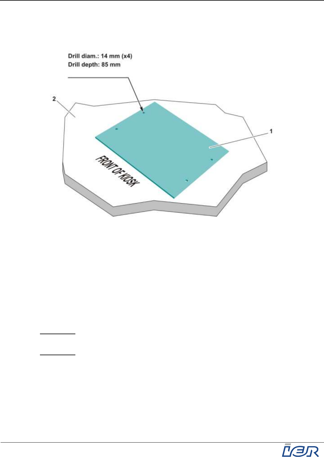
Using the drilling template (1), transfer the position of the four holes to the floor (2).
Drill four 85 mm deep and 14 mm diam. holes.
Remove the template (1).
Figure 3.4
Placing the Drilling Template on the Ground
3.2.2.5 Anchoring the Internal Threaded Sleeves Chemically
Vacuum (or use air blow) to remove any debris from the four drill holes.
Fill the four holes to approximately one third with anchoring mortar.
Insert an internal threaded sleeve in each hole. Make sure they are flush with the floor
surface and that the mortar slightly overflows from the holes.
Remove the excess mortar, or, if there isn't much, remove the threaded sleeve and add more
mortar into the hole to make sure the sleeve is fully bedded in the mortar.
Remove and discard the protective caps of the threaded sleeves.
IMPORTANT It takes about four minutes for the mortar to set if the temperature of the
floor material is 20° C.
IMPORTANT Mortar cure time is 60 min., approximately.
IER 918F
Installation Guide
Ce document est la propriété d'IER et ne doit pas être reproduit ou communiqué sans autorisation écrite
This document is the property of IER and may not be reproduced or communicated without prior written authorization
Page 19
N0F352A1 – Rev. 1
May 20, 2011
3.2.2.6 Securing the Kiosk to the Floor
Tools Required / Maintenance Products:
Forklift
Security Allen wrench for tamper proof M5 type screws
Allen wrench for M8 type screws
TORX wrench for slotted M4 type TORX screws
TORX wrench for slotted M6 type TORX screws
Combination wrench, size 13 mm.
Procedure:
Ensure the floor surface is clean.
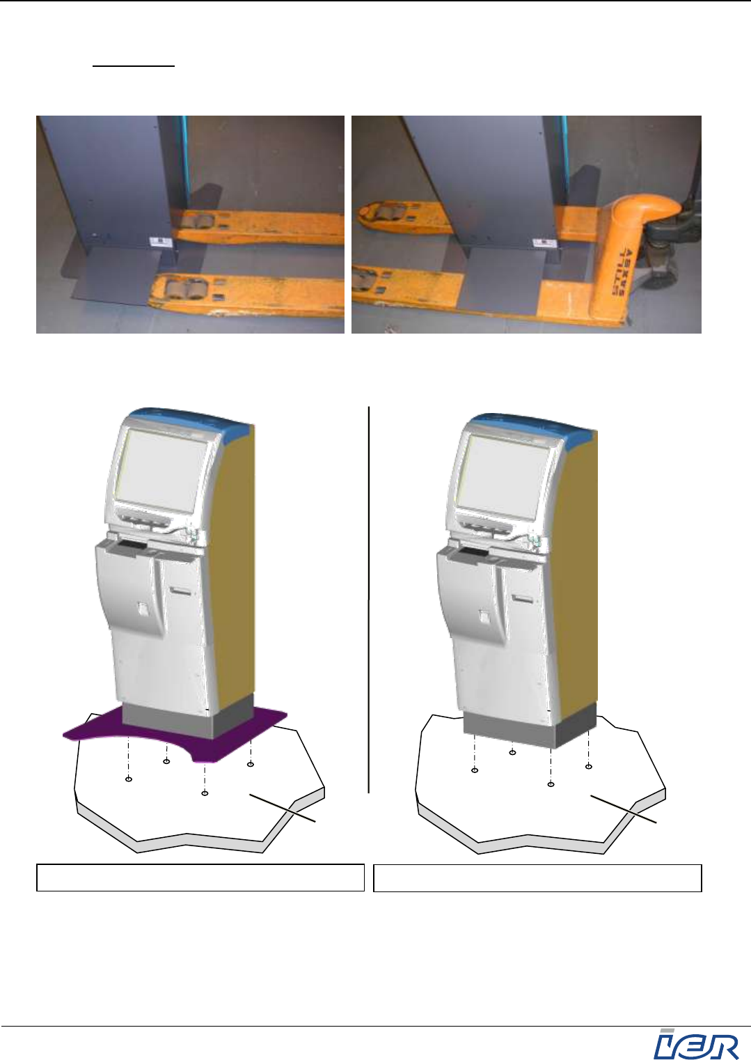
Secure the forklift transport plate (1) to the rear of the kiosk using the Allen wrench for M8 type
screws.
Slightly loosen the two baseboard mounting screws (2).
Remove the baseboard (2).
Figure 3.5
Moving the Kiosk
1
2
IER 918F
Installation Guide
Page 20
N0F352A1 – Rev. 1
May 20, 2011
Ce document est la propriété d'IER et ne doit pas être reproduit ou communiqué sans autorisation écrite
This document is the property of IER and may not be reproduced or communicated without prior written authorization
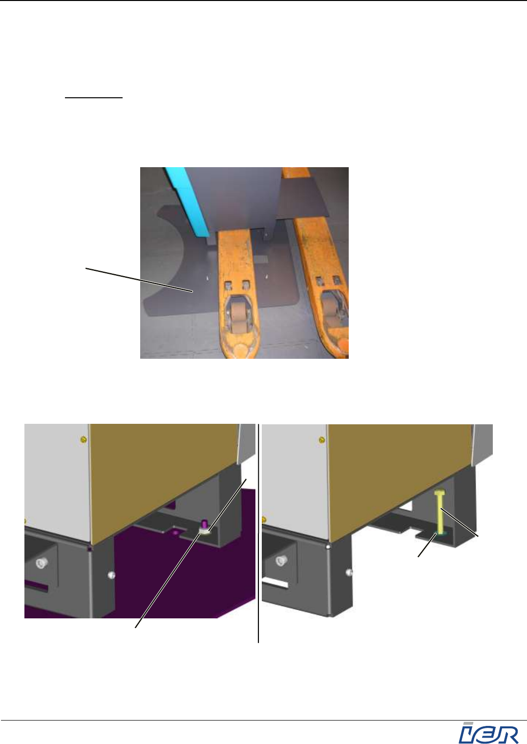
Place the forklift under the kiosk.
IMPORTANT To avoid any accident or damage to the kiosk, it is mandatory that you hold on
to it with the help of a second technician, before lifting it.
Using the forklift, move the kiosk to the site of installation.
Figure 3.6
Moving the Kiosk (cont’d)
Place the kiosk on its site of installation (3).
Figure 3.7
Securing the Kiosk to the Ground
3
Kiosk with floor mounting plate
Kiosk without floor mounting plate
3
IER 918F
Installation Guide
Ce document est la propriété d'IER et ne doit pas être reproduit ou communiqué sans autorisation écrite
This document is the property of IER and may not be reproduced or communicated without prior written authorization
Page 21
N0F352A1 – Rev. 1
May 20, 2011
If the kiosk is to be installed with the floor mounting plate:
With the forklift, center the kiosk in relation to the four holes in the floor.
Place the kiosk on the floor and remove the forklift.
Screw in and tighten the four bolts (4) with their respective washers (5) using the 13-mm
combination wrench.
Figure 3.8
Installing a Kiosk with Floor Mounting Plate
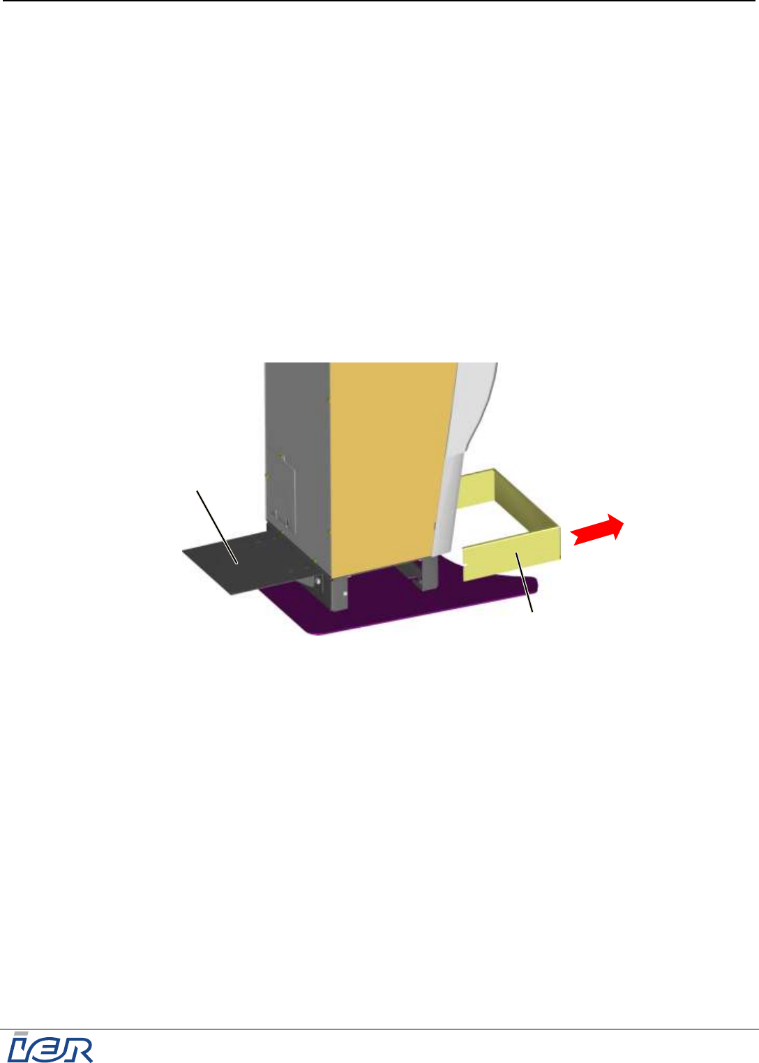
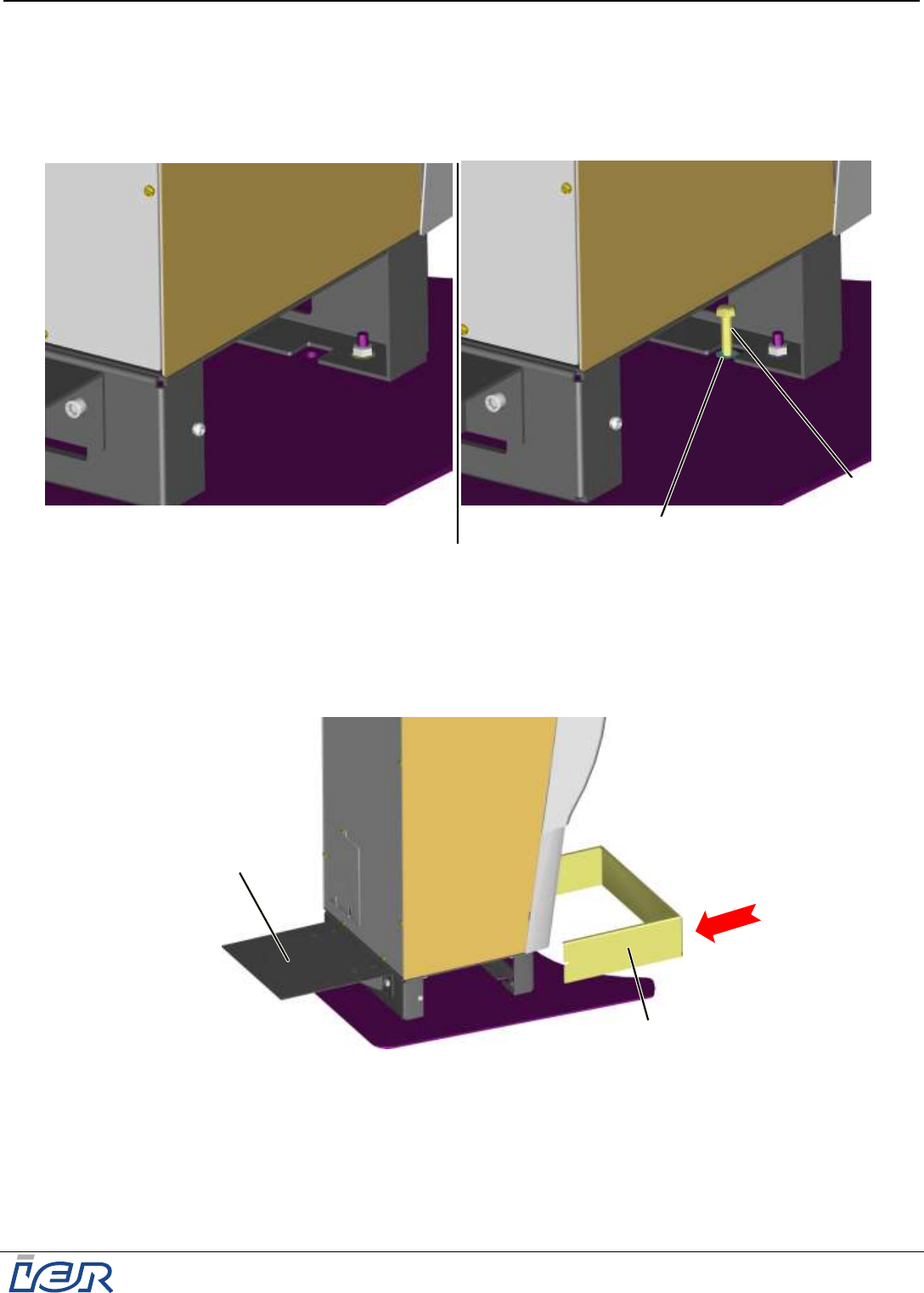
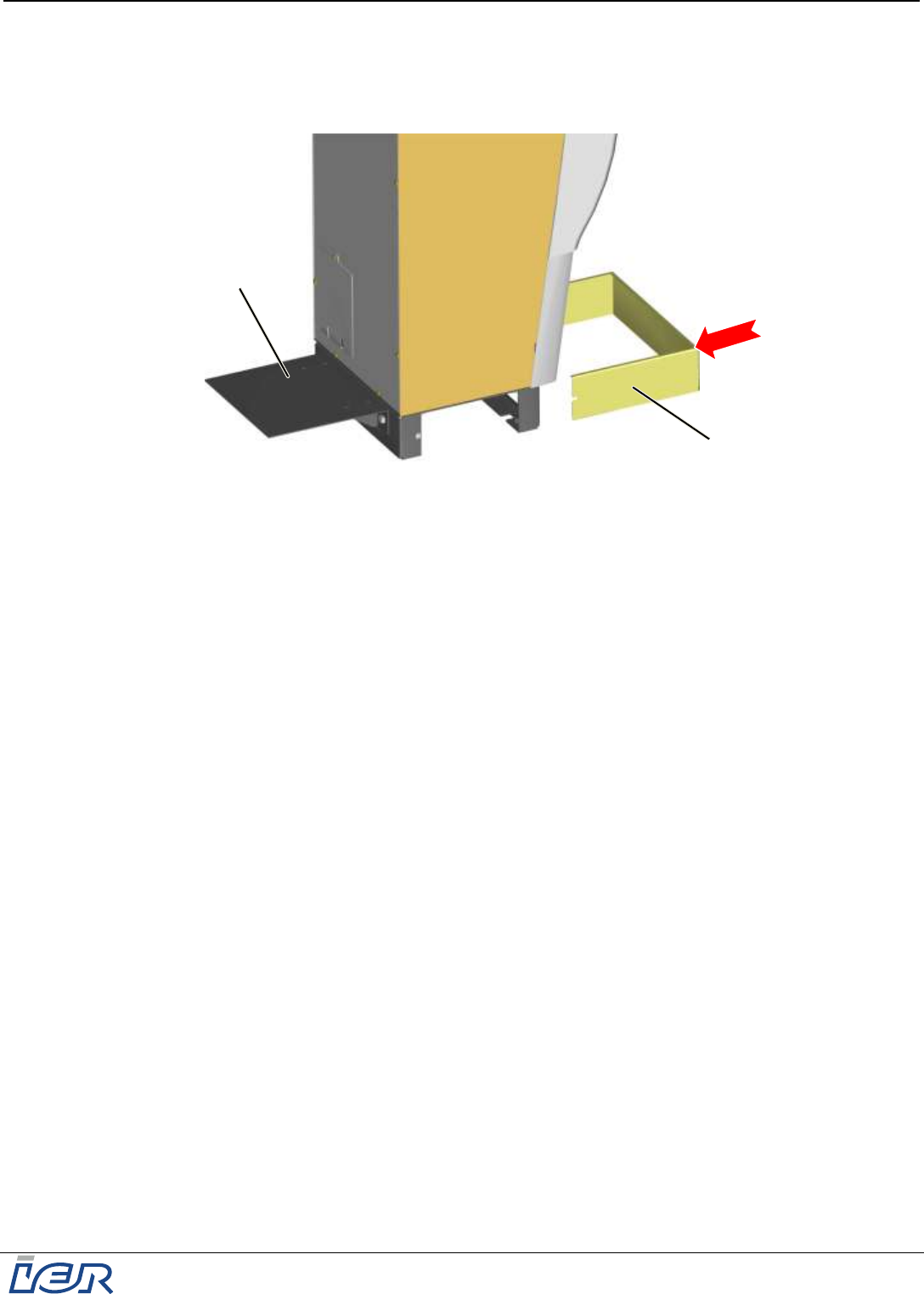
At the rear of the kiosk, remove the forklift transport plate (1) using the ALLEN wrench for M8
type screws.
Install the baseboard (2).
Tighten the two baseboard (2) fastening screws.
Figure 3.9
Installing the Baseboard
1
2
5
4
IER 918F
Installation Guide
Page 22
N0F352A1 – Rev. 1
May 20, 2011
Ce document est la propriété d'IER et ne doit pas être reproduit ou communiqué sans autorisation écrite
This document is the property of IER and may not be reproduced or communicated without prior written authorization
If the kiosk is to be installed without the floor mounting plate:
With the forklift, center the kiosk in relation to the four holes in the floor.
Place the kiosk on the floor and remove the forklift.
Remove the four nuts (6) and respective washers (7) using the 13-mm combination wrench.
IMPORTANT To avoid any accident or damage to the kiosk, it is mandatory that you hold on
to it with the help of a second technician, before lifting it.
Place the forklift again under the kiosk and lift it about three centimeters (one inch).
Remove the floor mounting plate (8).
Place the kiosk on the floor and remove the forklift.
Figure 3.10
Removing the Floor Mounting Plate
Screw in and tighten the four bolts (9) with their respective washers (10) using the 13-mm
combination wrench.
Figure 3.11
Installing a Kiosk without Floor Mounting Plate
7
6
10
9
8
IER 918F
Installation Guide
Ce document est la propriété d'IER et ne doit pas être reproduit ou communiqué sans autorisation écrite
This document is the property of IER and may not be reproduced or communicated without prior written authorization
Page 23
N0F352A1 – Rev. 1
May 20, 2011
At the rear of the kiosk, remove the forklift transport plate (1) using the ALLEN wrench for M8
type screws.
Install the baseboard (2).
Tighten the two baseboard (2) fastening screws.
Figure 3.12
Installing the Baseboard
1
2
IER 918F
Installation Guide
Page 24
N0F352A1 – Rev. 1
May 20, 2011
Ce document est la propriété d'IER et ne doit pas être reproduit ou communiqué sans autorisation écrite
This document is the property of IER and may not be reproduced or communicated without prior written authorization
3.2.3 Installation Procedure for Kiosks not Anchored to the Floor
Place the kiosk in the designated location.
Fully open the IER 918F Kiosk (see page 12).
3.2.4 Connecting the Kiosk
Tools Required / Maintenance Products:
Torx wrench for M4 type slotted Torx screws
Flat-head screwdriver for 3.5 mm slotted head screws.
CAUTION
MAKE SURE THERE IS NO VOLTAGE PRESENT BEFORE STARTING TO
CONNECT THEKIOSK ELECTRICALLY.
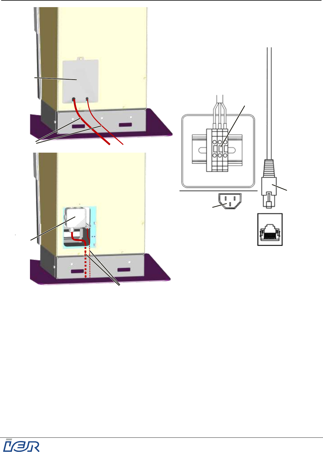
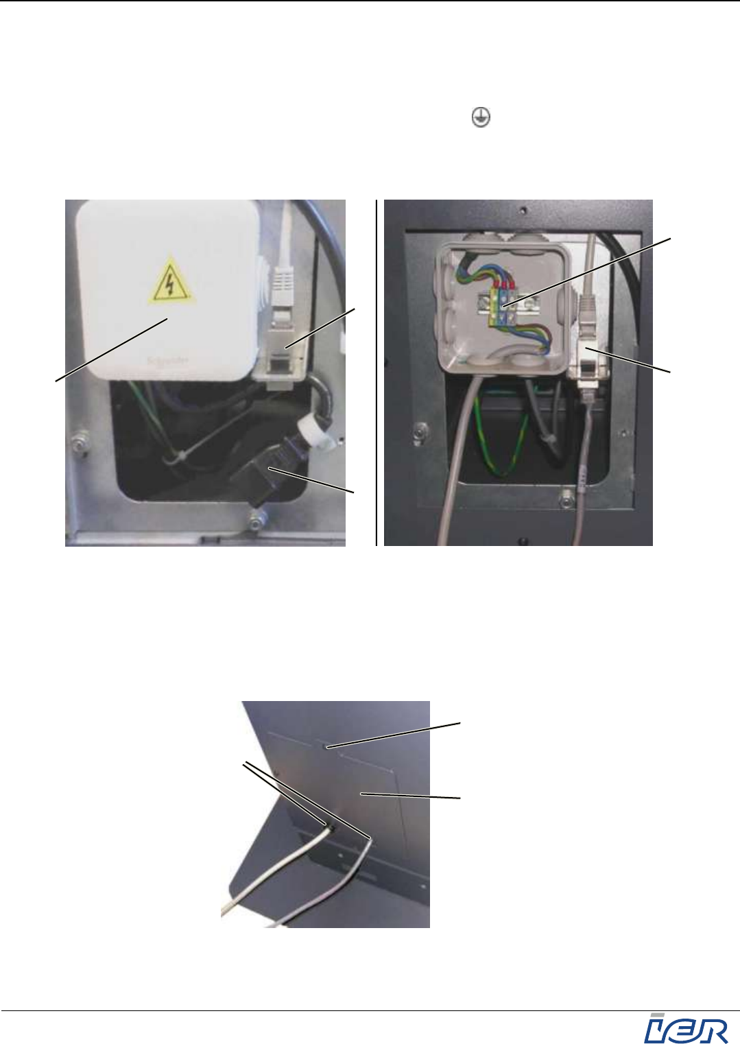
At the rear of the IER 918F Kiosk:
Use the Torx wrench for M4 type Torx screws to remove the cable duct cover plate (2)
fastening screw (1).
Remove the cable duct cover plate (2) to get access to the power connector (3) and the
network port (6).
Note If a 3-conductor power cable without connector is used to connect the kiosk to the power
source, remove the cable duct cover plate (2) to gain access the interconnection box (4) and to
the network port (6).
The IER 918F kiosk can be connected via the following two methods:
Through the rear of the kiosk (see figure page 25) or
From underneath (see figure page 25).
Figure 3.13
Connecting the Kiosk
2
1
3
6
4
IER 918F
Installation Guide
Ce document est la propriété d'IER et ne doit pas être reproduit ou communiqué sans autorisation écrite
This document is the property of IER and may not be reproduced or communicated without prior written authorization
Page 25
N0F352A1 – Rev. 1
May 20, 2011
Figure 3.14
Connecting the Kiosk through the Rear or from Underneath
2 : Cable duct cover plate
3 : Power connector (if a power cable with an IEC type power connector is used)
4 : Interconnection box
5 : Terminal block (for connection with a 3-conductor power cable without connector)
6 : Network port (Ethernet connection / RJ45 connector)
7 : Cable passage through rear of the kiosk
8 : Cable passage from underneath the kiosk
8
6
3
2
7
5
4
IER 918F
Installation Guide
Page 26
N0F352A1 – Rev. 1
May 20, 2011
Ce document est la propriété d'IER et ne doit pas être reproduit ou communiqué sans autorisation écrite
This document is the property of IER and may not be reproduced or communicated without prior written authorization
Connect the power cable (not supplied) to the power connector (3)
Note If a 3-conductor power cable without connector (not supplied) is used to connect the kiosk to
the power source, remove the interconnection box cover (4) to gain access to the terminal block
(5). Remove the power cable with connector (3) and connect the 3-conductor power cable to the
terminal block (5) in the following way:
Ground conductor to the green and yellow PE terminal
Neutral conductor to the blue terminal
Phase conductor to the grey terminal
Connect the network cable (not supplied) to the network port (6).
Figure 3.15
Connecting the Kiosk to the Power Source and the Network
Note When connecting the kiosk through the rear, place a split grommet (9) on the power cable and
the network cable before inserting them into the slots in the cable duct cover plate (2) to protect
them.
Install the cable duct cover plate (2)
Use the Torx wrench for M4 type screws to fasten screw (1).
Figure 3.16
Connecting the Kiosk to the Power Source and the Network (Final Step)
1
9
2
6
4
6
5
3
IER 918F
Installation Guide
Ce document est la propriété d'IER et ne doit pas être reproduit ou communiqué sans autorisation écrite
This document is the property of IER and may not be reproduced or communicated without prior written authorization
Page 27
N0F352A1 – Rev. 1
May 20, 2011
4 POWERING UP/POWERING DOWN THE KIOSK
4.1 POWERING UP THE IER 918F KIOSK
Fully open up the IER 918F Kiosk (see page 12).
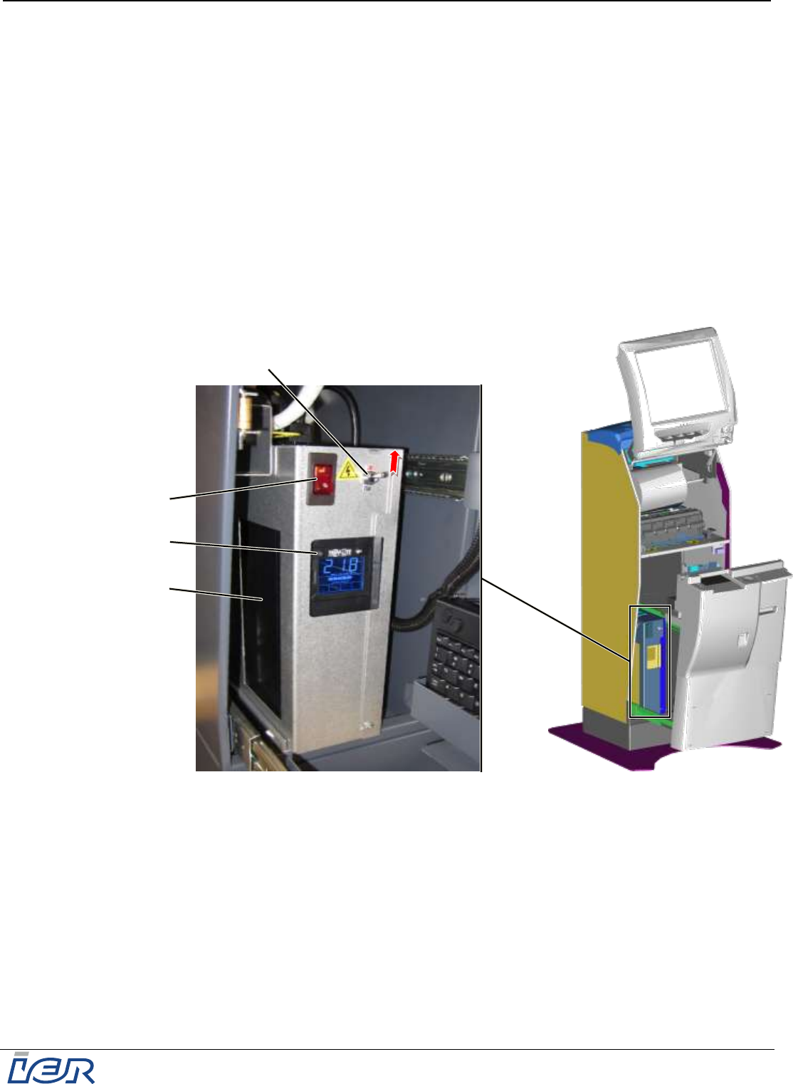
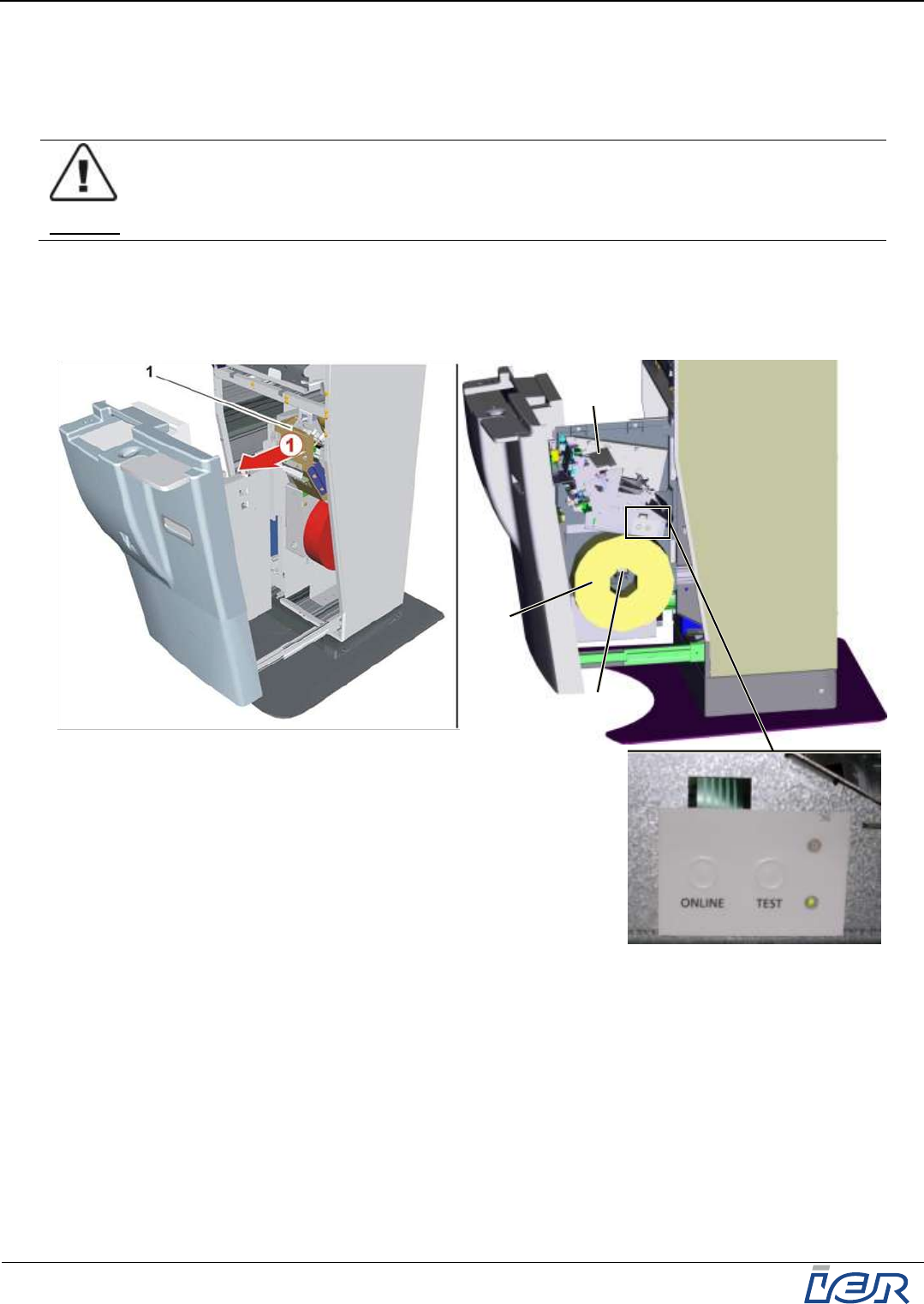
Press button (2) until you hear a beep (1) confirming that the UPS (optional) has started up.
Set switch (3) to the I-position to supply the UPS (1) with power.
To complete kiosk power up, set switch (4) to the I-position. This causes switch (4) to light up.
Note Check that the UPS (1) is supplied with power.
Close the IER 918F Kiosk (see page 12).
Note Having carried out these steps, wait for the operating system to be loaded and for the
operational modules of the kiosk to be initialized.
Note
Figure 4.1
Powering Up the IER 918F Kiosk
1
2
4
3
IER 918F
Installation Guide
Page 28
N0F352A1 – Rev. 1
May 20, 2011
Ce document est la propriété d'IER et ne doit pas être reproduit ou communiqué sans autorisation écrite
This document is the property of IER and may not be reproduced or communicated without prior written authorization
4.2 POWERING DOWN THE IER 918F KIOSK
4.2.1 Shutting Down Windows
Use the maintenance keyboard to shut down Windows:
a) First Method
Simultaneously press the Ctrl + Alt + S keys to close all open applications.
Press the Windows key on the keyboard.
Figure 4.2
Windows Key on the Keyboard
Select the Start and then the Turn off computer button displayed in the lower left corner of the
screen.
Select Turn off from the drop down menu in the Shut down Windows dialog box.
b) Second Method
Simultaneously press the Ctrl + Alt + S keys to close all open applications.
Simultaneously press the Ctrl + Alt + Del keys to close Windows.
In the Windows Task Manager window displayed, select the Shut Down menu and select
Turn off from the drop down menu.
Wait for the operating system to fully shut down.
4.3 POWERING DOWN THE KIOSK
Refer to the illustration, see figure page 27.
Set the power switch (4) to the 0-position.
To power down the UPS (1), press button (2) for a few seconds (i.e. until you hear a beep).
Set switch (3) to the 0-position to cut the power to the UPS (1).
Close the IER 918F Kiosk (see page 12).
IER 918F
Installation Guide
Ce document est la propriété d'IER et ne doit pas être reproduit ou communiqué sans autorisation écrite
This document is the property of IER and may not be reproduced or communicated without prior written authorization
Page 29
N0F352A1 – Rev. 1
May 20, 2011
5 LOADING THE CONSUMABLES
5.1 GENERAL PURPOSE THERMAL PRINTER (GPP)
5.1.1 Media Loading Procedure
Power up the kiosk (see page 27).
CAUTION
THE PRINTHEAD IS A SENSITIVE ELECTRONIC COMPONENT. PROCEED WITH CARE.
AVOID PHYSICAL SHOCKS TO THE PRINTHEAD
DO NOT USE ANY TOOLS THAT COULD DAMAGE THE PRINTHEAD
DO NOT TOUCH THE PRINTHEAD HEATING ELEMENTS
Open the display assembly in the upper part of the kiosk (see page 12).
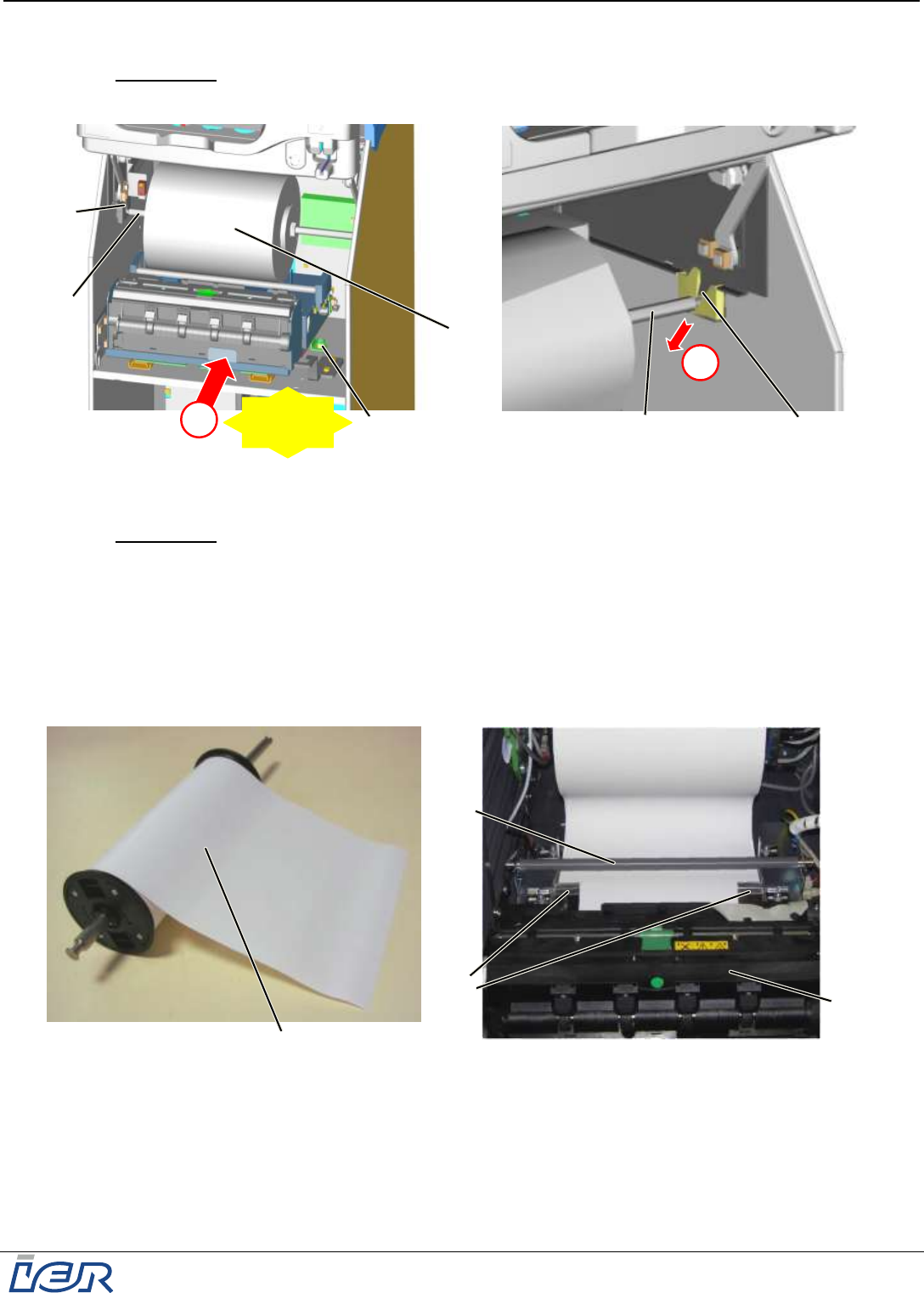
Make sure the printer power switch (1) is lit.
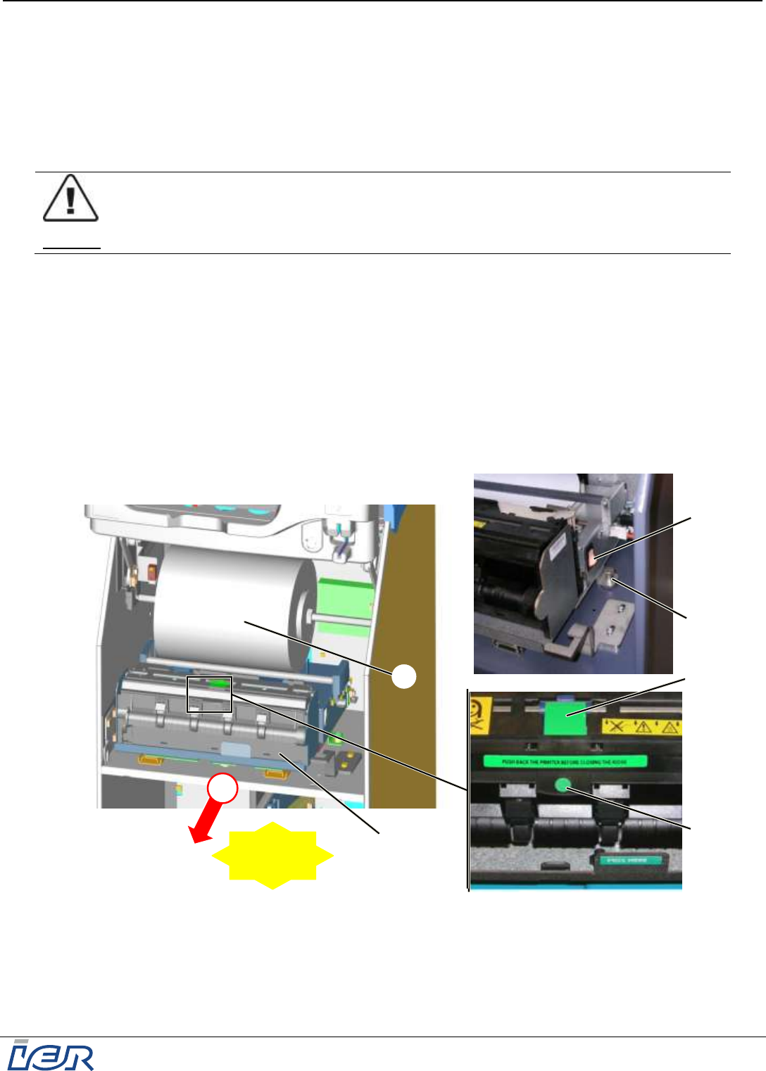
Step 1: lift pin (2) and pull the printer (if necessary by guiding it) fully (5) out of the kiosk, until
you hear a clicking sound confirming the printer is locked in its pulled position.
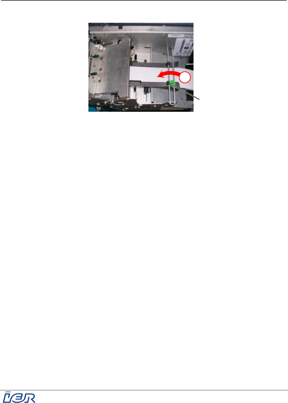
Press the green printer cover release latch (5) to open the printhead.
Grasp tab (4) (green dot) and lift the printhead.
Remove the roll media (6) from the printer (3).
Press on tab (4) to close the printhead.
Figure 5.1
Loading the GPP with Roll Media: Sliding the Printer out of the Housing
1
2
5
4
! CLICK !
1
6
3
IER 918F
Installation Guide
Page 30
N0F352A1 – Rev. 1
May 20, 2011
Ce document est la propriété d'IER et ne doit pas être reproduit ou communiqué sans autorisation écrite
This document is the property of IER and may not be reproduced or communicated without prior written authorization
Step 2: Lift the roll media (6) out of the two notches (7) and remove it from the kiosk.
Figure 5.2
Loading the GPP with Roll Media: Removing the Media Roll
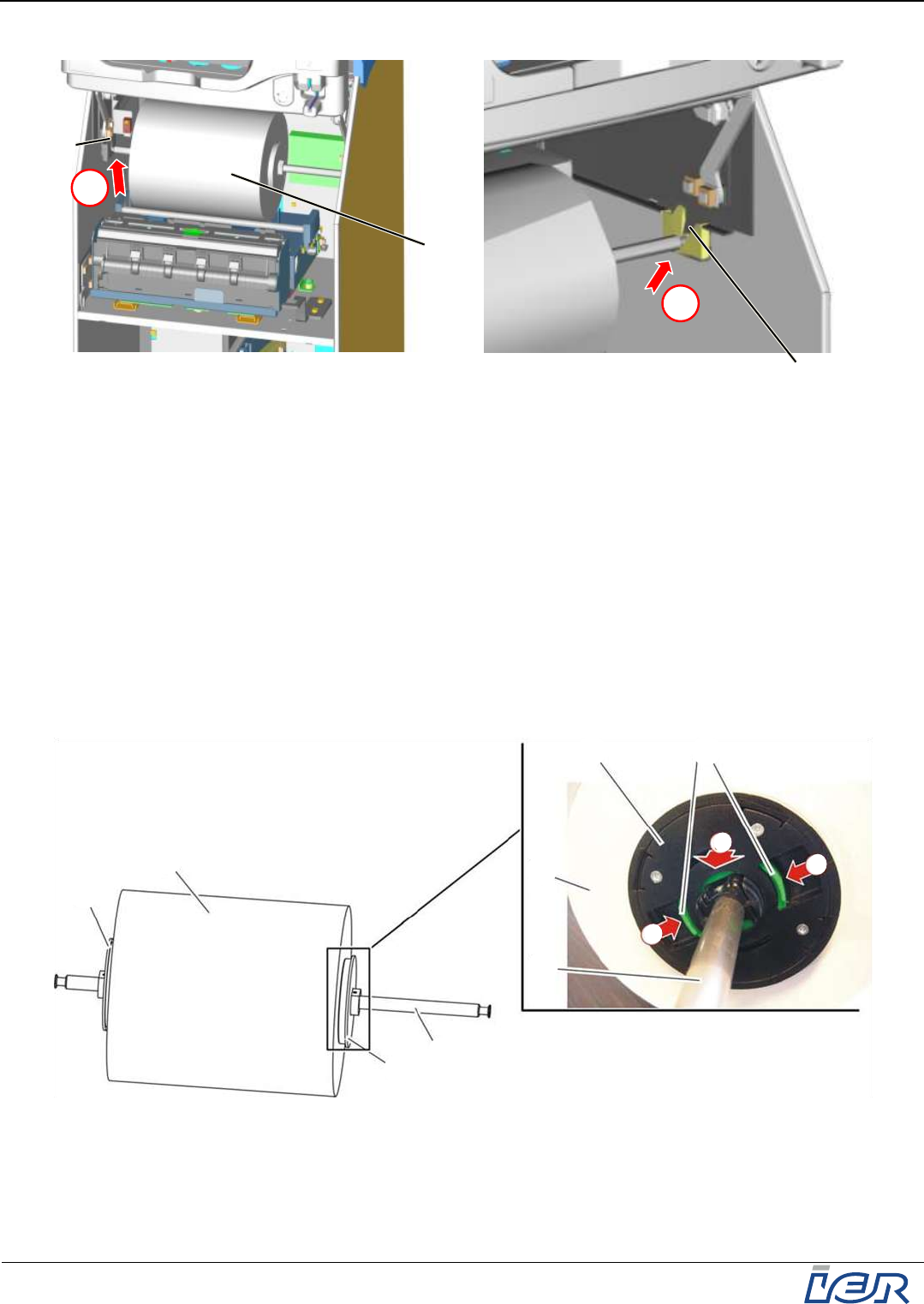
Step 3: Grasp the two levers (8) and press them to unlock the removable flange (9).
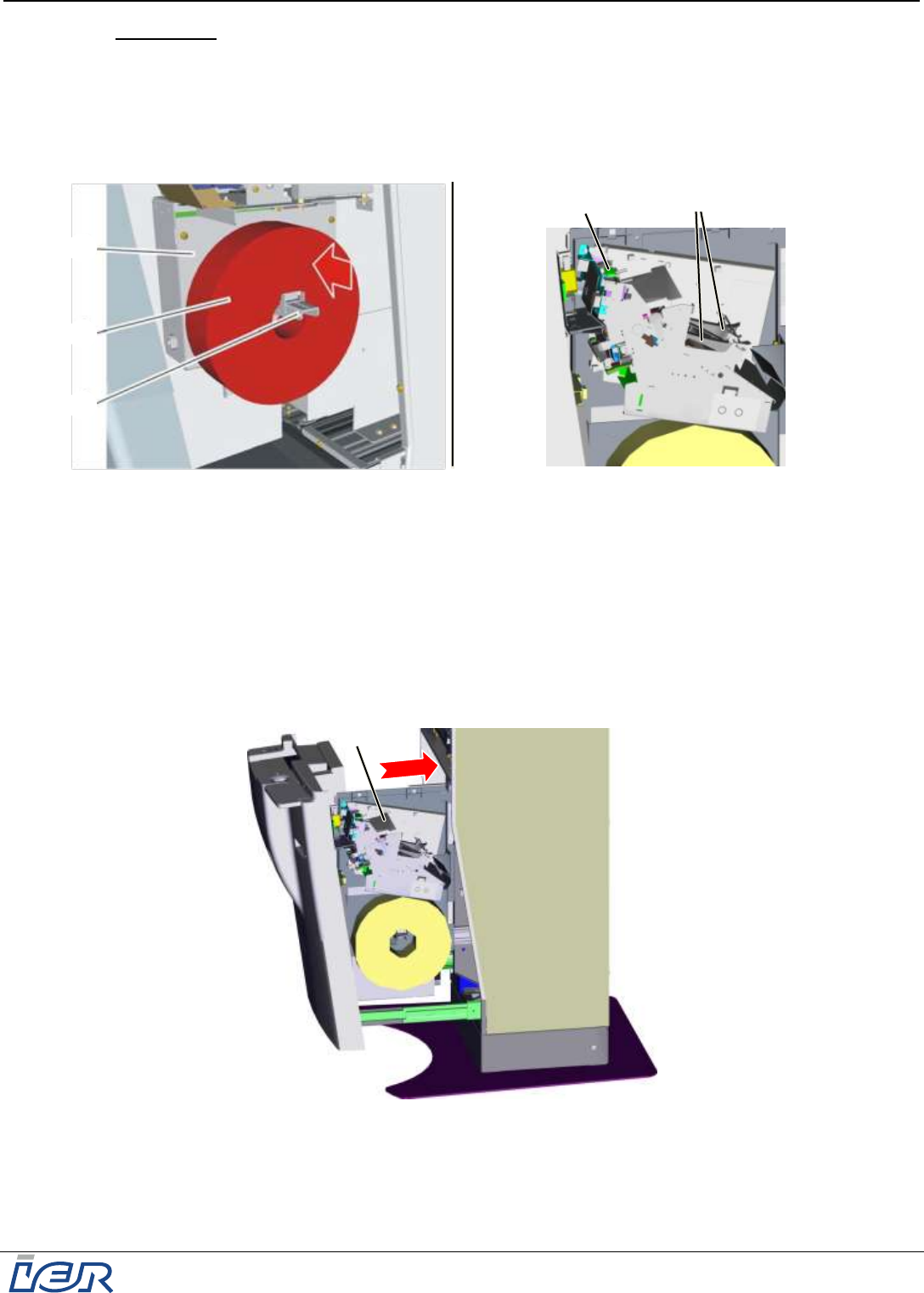
Step 4: Slide the removable flange (9) off shaft (10).
Place a new media roll (6) on the shaft and set it against fixed flange (11), used as stop
piece.
Note Make sure the new media roll (6) is tightly set against the fixed flange.
Slide the removable flange (9) on shaft (10) while pressing the two levers (8) until the media
roll (6) is firmly held in place by the two flanges (9) and (11).
Release the two levers (8) to lock the removable flange (9).
Figure 5.3
Loading the GPP with Roll Media: Changing the Media Roll
8
9
10
10
9
11
3
3
4
6
6
2
7
2
6
7
IER 918F
Installation Guide
Ce document est la propriété d'IER et ne doit pas être reproduit ou communiqué sans autorisation écrite
This document is the property of IER and may not be reproduced or communicated without prior written authorization
Page 31
N0F352A1 – Rev. 1
May 20, 2011
Step 5: Install the media roll (6) /shaft (10) assembly in the two notches (7).
IMPORTANT To make sure the media roll (6) has been replaced correctly, check that both
ends of shaft (10) are correctly seated at the bottom of the notches (7).
Figure 5.4
Loading the GPP with Roll Media: Installing a New Media Roll
IMPORTANT When installing the roll media (6), check that the heat-sensitive side of the
media is facing up (see figure below).
Feed the roll media (6) under shaft (12) and into the two paper guides (13).
Push the media into the printer (3) until it is taken up by the latter.
Note Once the media has been drawn into the printer, the following happens:
the printer is initialized and the media is correctly positioned
a blank document is cut and delivered through the output slot.
Figure 5.5
Loading the GPP with Roll Media
Step 6: Lift pin (2) and push the printer (3) back into the housing to the home
position
(a
clicking sound confirms that printer has been locked into the home position).
Close the IER 918F Kiosk display assembly (see page 12).
12
13
3
6
5
7
6
7
6
10
10
2
! CLICK !
IER 918F
Installation Guide
Page 32
N0F352A1 – Rev. 1
May 20, 2011
Ce document est la propriété d'IER et ne doit pas être reproduit ou communiqué sans autorisation écrite
This document is the property of IER and may not be reproduced or communicated without prior written authorization
5.2 BAG TAG PRINTER (OPTION)
5.2.1 Media Loading Procedure
Power up the kiosk (see page 27).
CAUTION
THE PRINTHEAD IS A SENSITIVE ELECTRONIC COMPONENT. PROCEED WITH CARE.
AVOID PHYSICAL SHOCKS TO THE PRINTHEAD
DO NOT USE ANY TOOLS THAT COULD DAMAGE THE PRINTHEAD
DO NOT TOUCH THE PRINTHEAD HEATING ELEMENTS
Open the lower part of the IER 918F Kiosk (see page 13).
Pull the Bag Tag printer (1) fully out of the kiosk housing, to the stop (to avoid any possible
paper jams).
Figure 5.6
Loading the Bag Tag Printer with Media: Pulling the Bag Tag Printer Out of the Kiosk Housing
If there is any media (2) left in the paper path, press the TEST key for at least 2 seconds to
unload it from the printer (1).
2
1
3
IER 918F
Installation Guide
Ce document est la propriété d'IER et ne doit pas être reproduit ou communiqué sans autorisation écrite
This document is the property of IER and may not be reproduced or communicated without prior written authorization
Page 33
N0F352A1 – Rev. 1
May 20, 2011
IMPORTANT When installing the new media roll, make sure the heat-sensitive side faces up.
Remove the old media roll (2) from the media hanger (3).
Place the new media roll (2) on the media hanger (3) and set it tightly against fixed flange (4).
Make sure the printhead is locked.
If not, firmly press on tab (5) to lock the printhead.
Insert the leading tag of the new media roll into the two paper guides (6).
Figure 5.7
Loading the Bag Tag Printer with Media: Installing the Media Roll
Push the media into the printer until it is sensed by the printer and drawn in.
Note Once the media has been drawn into the printer, the following happens:
the printer is initialized and the media is correctly positioned according to the program
parameters and depending on the type of positioning marks present on the media
a blank document is placed in the output slot.
Push the Bag Tag printer (1) back into the kiosk housing to the home position.
Close the IER 918F kiosk lower part (see page 13).
Figure 5.8
Loading the Bag Tag Printer with Media
1
3
2
4
6
5
IER 918F
Installation Guide
Page 34
N0F352A1 – Rev. 1
May 20, 2011
Ce document est la propriété d'IER et ne doit pas être reproduit ou communiqué sans autorisation écrite
This document is the property of IER and may not be reproduced or communicated without prior written authorization
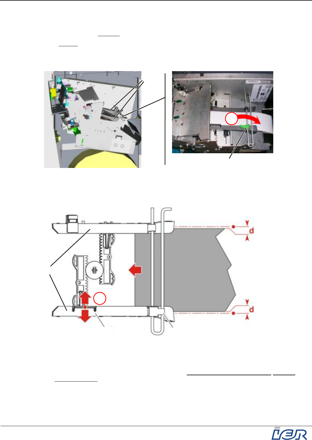
5.2.2 Adjusting the Width of the Paper Path
Note The two paper guides (6) need to be adjusted such that:
media feed is accurate (paper guides allowing only little play) but
smooth (no excessive friction)
Procedure:
Step 1: Release the paper guide locking lever (7) by rotating it towards the rear of the printer.
Figure 5.9
Adjusting the Width of the Paper Path
Step 2: Grasp the paper guide adjustment tab (8) and increase the distance between the two
paper guides (6).
Figure 5.10
Adjusting the Width of the Paper Path (cont’d)
Insert the media into the two paper guides and push it in a short distance.
Fine adjust the paper path width to make sure that media feed is smooth and accurate
at the same time (allow for some play, i.e. distance d in above illustration).
8
7
2
6
1
7
6
IER 918F
Installation Guide
Ce document est la propriété d'IER et ne doit pas être reproduit ou communiqué sans autorisation écrite
This document is the property of IER and may not be reproduced or communicated without prior written authorization
Page 35
N0F352A1 – Rev. 1
May 20, 2011
Step 3: Lock the position of the guides by rotating the locking lever (7) towards the front of the
printer.
Figure 5.11
Adjusting the Width of the Paper Path (Final Step)
3
7
IER 918F
Installation Guide
Page 36
N0F352A1 – Rev. 1
May 20, 2011
Ce document est la propriété d'IER et ne doit pas être reproduit ou communiqué sans autorisation écrite
This document is the property of IER and may not be reproduced or communicated without prior written authorization
6 TEST
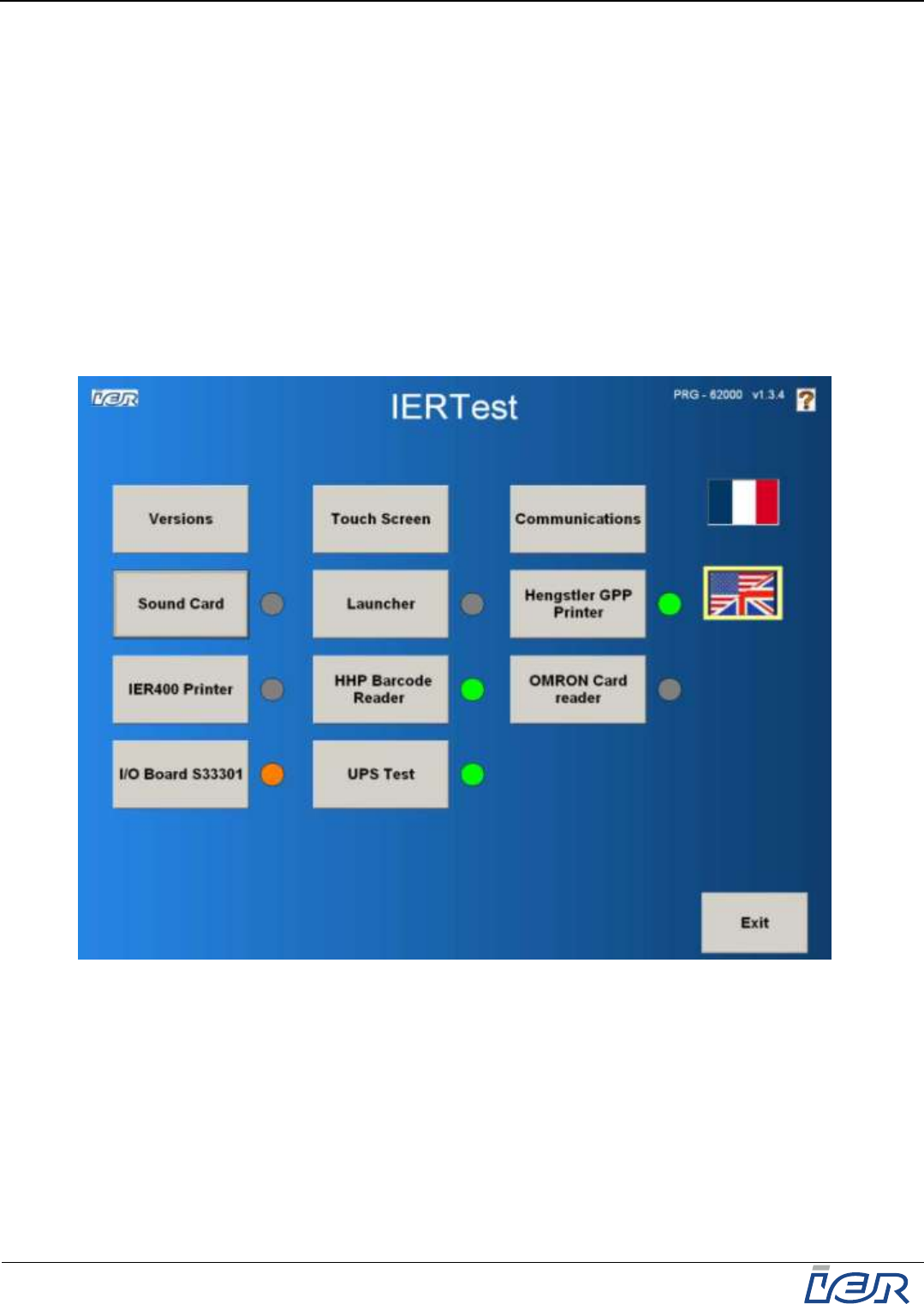
6.1 TESTING THE KIOSK FUNCTIONS - IER TEST UTILITY
The embedded IER TEST utility checks the operational states of the sensors and actuators,
ensuring device safety, indicator operation and operability of the kiosk functions.
The IER Test Utility comes with an interactive graphical user interface displayed on the touch
screen of the kiosk. In addition to displaying the various screens allowing you to check device
operation, the utility also makes it possible to enter inventory data and incident handling data, and
allows tracking the quantity of media used for kiosk maintenance.
Note The IER TEST utility is factory installed on the hard drive of the kiosk, except if otherwise
specified by the customer.
After powering up the kiosk and loading the consumables, check the various kiosk modules
using the IER TEST utility.
Figure 6.1
IER TEST Utility Home Page
Should the tests reveal a problem on one of the modules, contact the help desk.