INMUSIC ACV5 MPC with touch display User Manual
INMUSIC BRANDS INC MPC with touch display Users Manual
UserManual.wiki
>
INMUSIC
>
ACV5 User Manual
>
Users Manual
Contents
1.
Users Manual_Safety Warranty
2.
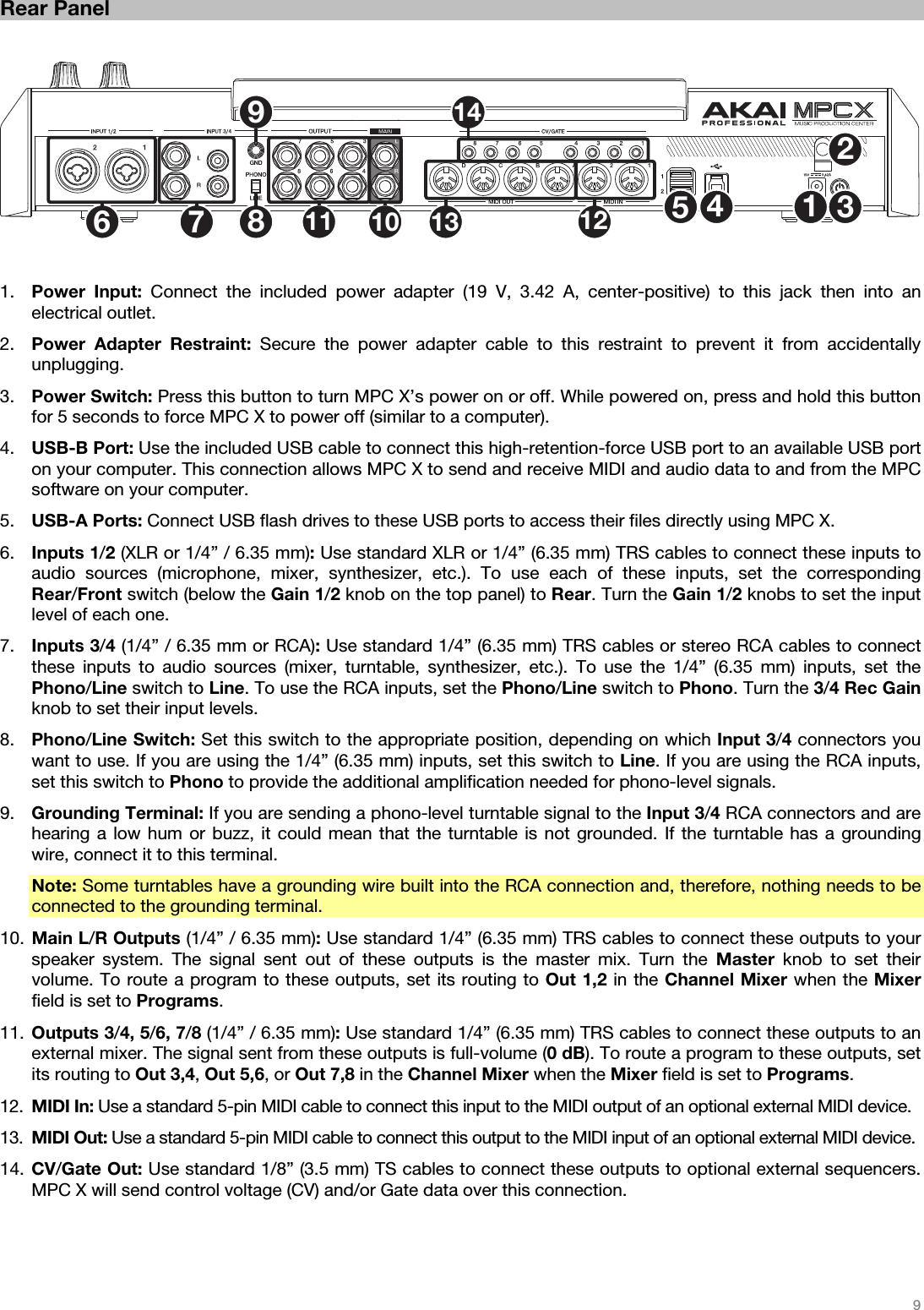
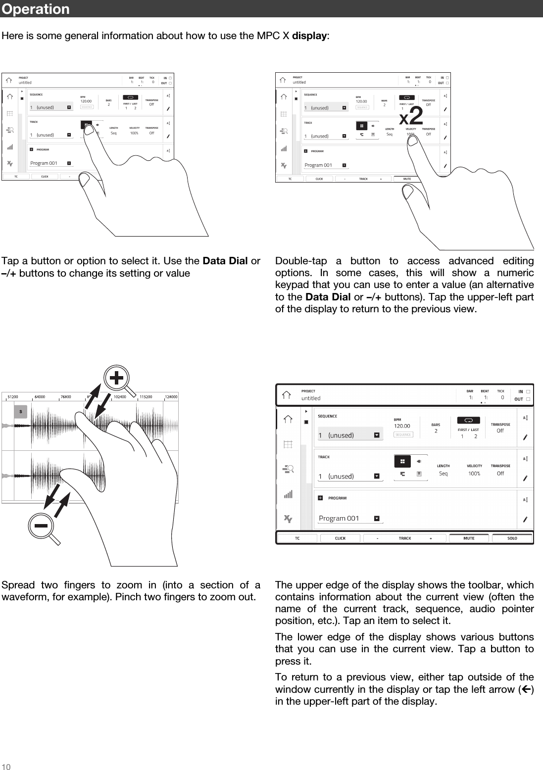
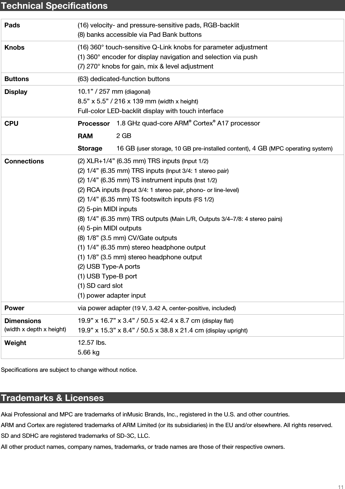
Users Manual
Users Manual
Navigation menu
Upload a User Manual
Namespaces
Wiki Guide
HTML
PDF
Info
Views
User Manual
Discussion / Help
Navigation