INMUSIC ACV5 MPC with touch display User Manual
INMUSIC BRANDS INC MPC with touch display Users Manual
INMUSIC >
Contents
- 1. Users Manual_Safety Warranty
- 2. Users Manual
Users Manual
Quickstart Guide
English ( 2 – 11 )
2
Introduction
Features
• Standalone MPC—no computer required
• 10.1” (257 mm) full-color multi-touch display
• Also acts as a control surface for MPC 2.0 software
• Phono inputs with ground peg
• (16) Q-Link knobs with graphical displays
• (2) full-size MIDI inputs and (4) full-size MIDI outputs
• 16 GB of on-board storage (over 10 GB of sound content included)
• 2 GB of RAM for sampling
• Full-size SD card slot
• User-expandable 2.5” SATA drive connector (SSD or HDD)
• (2) USB-A 3.0 slots for thumb drives or MIDI controllers
Box Contents
MPC X
Power Adapter
USB Cable
Software Download Card
Quickstart Guide
Safety & Warranty Manual
Important: Visit akaipro.com and find the webpage for MPC X to download the complete user guide.
Support
For the latest information about this product (documentation, technical specifications, system requirements,
compatibility information, etc.) and product registration, visit akaipro.com.
For additional product support, visit akaipro.com/support.
3
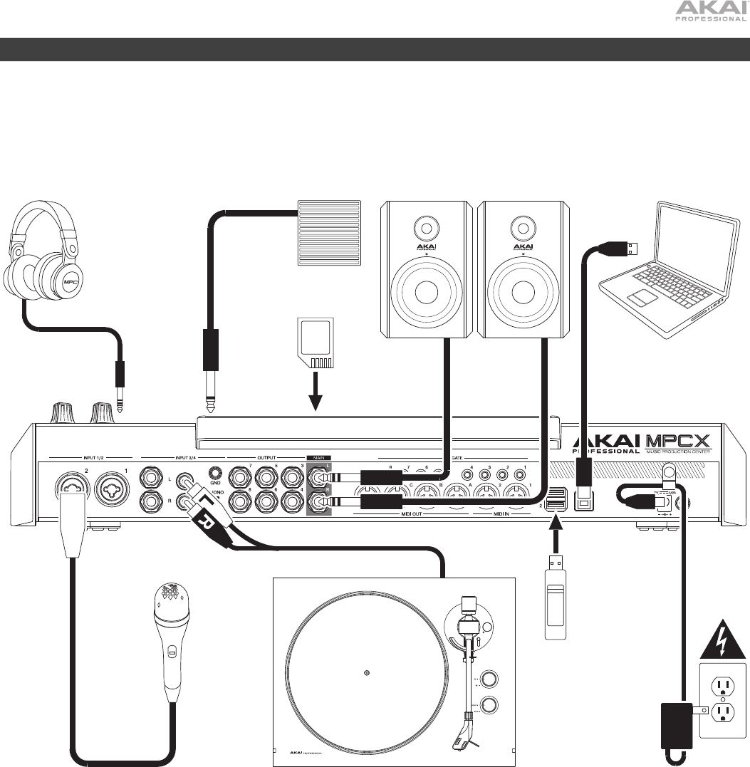
Setup
Items not listed under Introduction > Box Contents are sold separately.
Headphones
(to front-panel headphone output)
Footswitch
(to FS 1)
Powered Monitors Computer
SD Card
(to SD card slot)
Turntable Microphone Power Outlet
USB
Flash
Drive
4
Features
Important: Visit akaipro.com and find the webpage for MPC X to download the complete user guide.
Top Panel
1
2
3
4
5
6
7
8
9
10
21
28 29 30
32 33
34 35
36
37 38
39 40
41
42
43
44
47 48
49
50
51 52
53 54
55 55
45 45
46
44
31
23 24 25 26 27
22
12
15
11
13
16 17 18 19 20
14
Navigation & Data Entry Controls
1. Display: This full-color multi-touch display shows information relevant to MPC X’s current operation. Touch the
display (and use the hardware controls) to control the MPC interface. See Operation to learn how to use some
basic functions.
Tip: If you adjust the angle of the display, we recommend using the stand on its back panel to secure it in place.
2. Cursors: Press these buttons to navigate through the fields of menus and options shown in the display.
3. Data Dial: Turn this dial to scroll through the available menu options or adjust the parameter values of the
selected field in the display.
4. –/+: Press these buttons to increase or decrease the value of the selected field in the display.

5
5. Numeric Keypad: If the selected field in the display is a number, press these numbered buttons as a standard
numeric keypad to enter a value. Press the keypad’s Enter to enter it.
6. Undo/Redo: Press this button to undo your last action.
Press and hold Shift and press this button to redo the last action you undid.
7. Shift: Press and hold this button to access some buttons’ secondary functions (indicated by red writing).
8. F-Key: Press and hold this button to use the 6 buttons under the display (Menu, Browse, Step Seq, Sampler,
XYFX, Looper) to select one the 6 options shown at the bottom edge of the display. In other words, instead of
tapping one of the 6 buttons in the display, you can press one of these hardware buttons under it.
Pad & Q-Link Controls
9. Q-Link Knobs: Turn these touch-sensitive knobs to adjust various parameters and settings. The display strip
above each knob indicates the parameter it is controlling and its current value or setting.
10. Pads: Press these pads to trigger drum hits or other samples in your software. The pads are velocity-sensitive
and pressure-sensitive, which makes them very responsive and intuitive to play. The pads will light up different
colors, depending on how hard you play them (ranging from yellow at a low velocity to red at the highest
velocity). You can also customize their colors.
11. Pad Bank: Press these buttons to access Pad Banks A–D.
Press and hold Shift while pressing these buttons to access Pad Banks E–H.
12. Copy/Delete: Press this button to copy one pad to another. When the From Pad field is selected, press the
“source” pad (the pad you want to copy). When the To Pad graphic (of all pads) is selected, press the
“destination” pad. You can select multiple destination pads, and you can select pads in different pad banks. Tap
Do It to continue or Cancel to return to the previous screen.
Press and hold Shift and press this button to delete the samples from all layers of the currently selected pad.
13. Full Level/Half Level: Press this button to activate or deactivate the Full Level feature. When activated, the pads
will always trigger their samples at the maximum velocity (127), regardless of how much force you use.
Press and hold Shift and then press this button to activate or deactivate the Half Level feature. When activated,
the pads will always trigger their samples at half-velocity (64).
14. 16 Level: Press this button to activate or deactivate the 16 Level feature. When activated, the last pad that was
hit will be temporarily copied to all 16 pads. The pads will play the same sample as the original pad, but a
selectable parameter will increase in value with each pad number, regardless of how much force you use.
15. Note Repeat/Latch: Press and hold this button, and then press a pad to trigger that pad’s sample repeatedly.
The rate is based on the current tempo and Time Correct settings.
Press and hold Shift and then press this button to “latch” the Note Repeat feature. When latched, you do not
have to hold the Note Repeat button for it to be activated. Press Note Repeat once more to unlatch it.
16. Project: Press this button to use the Q-Link knobs to adjust parameters related to the currently selected project.
17. Program: Press this button to use the Q-Link knobs to adjust parameters of the currently selected program.
18. Pad Scene: Press this button to use the Q-Link knobs to adjust parameters that you have assigned for the
currently selected pad.
19. Pad Param: Press this button to use the Q-Link knobs to adjust one parameter across all 16 pads. Each Q-Link
knob corresponds to the pad with the same number and position in the 4-by-4 layout.
20. Screen Control/Edit: Press this button to use the Q-Link knobs to adjust parameters in the currently selected
mode as shown in the display.
Press and hold Shift and then press this button to enter Q-Link Edit Mode where you can assign other
parameters to the Q-Link knobs.

6
Mode & View Controls
21. Menu: Press this button to open the Menu where you can select any of the available modes. Tap an option to
enter that mode.
22. Main/Track: Press this button to view Main Mode, an overview of the most-used functions.
Press and hold Shift and press this button to view Track View Mode, an overview of the tracks of each sequence.
23. Browse/Save: Press this button to view the Browser. The Browser lets you navigate your computer’s internal
and external hard disks to load samples, sequences, songs, etc. Using filter buttons and user-definable folders,
you can easily adapt it to your workflow. You can also preview samples before loading them.
Press and hold Shift and press this button to save the current project (including its samples, programs,
sequences, and songs).
24. Step Seq/List Edit: Press this button to view the Step Sequencer where you can create or edit sequences by
using the pads as “step buttons,” simulating the experience of a traditional step-sequencer-style drum machine.
Press and hold Shift and press this button to view your sequences using the List Edit View instead of Grid View.
25. Sampler/Looper: Press this button to view the Sampler where you can record audio samples to use in your projects.
Press and hold Shift and press this button to view the Looper where you can record and overdub audio in real
time—a great tool for live performance as well as spontaneous moments in the studio. You can export the loop
as a sample to use in your project.
26. XYFX: Press this button to view XYFX Mode, which turns the touchscreen into an XY pad where each axis
represents the range of an effect parameter. As you move touch or move your finger on the touchscreen, the
current position will determine the current value of the two parameters. You can use this mode to create
interesting effect automation on your tracks.
27. Pad Perform: Press this button to view Pad Perform Mode where you can assign musical scales/modes, chords,
or progressions to the pads for creative performance options.
28. Prog Edit: Press this button to view Program Edit Mode, which contains all parameters for editing your programs.
29. Sample Edit: Press this button to view Sample Edit Mode where you can edit your samples using various
functions and processes.
30. Pad Mixer: Press this button to view the Pad Mixer where you can set a program’s levels, stereo panning,
routing, and effects.
31. Ch. Mixer: Press this button to view the Channel Mixer where you can set levels, stereo panning, and other
settings for your tracks, programs, returns, submixes, and masters.
32. Track Mute/Pad Mute: Press this button to view Track Mute Mode where you can easily mute tracks within a
sequence or set mute groups for each track.
Press and hold Shift and press this button to view Pad Mute Mode where you can easily mute pads within a
program or set mute groups for each pad within a program.
33. Next Seq/Song: Press this button to view Next Sequence Mode where you can trigger different sequences simply
by playing the pads. This is useful for live performances, letting you change a song’s structure in real time.
Press and hold Shift and press this button to view Song Mode where you can arrange sequences in a specific order
and/or repetition to create songs. You can edit the structure of a song during playback for easy, on-the-fly composing.
Transport & Recording Controls
34. Play: Press this button to play the sequence from the audio pointer’s current position.
35. Play Start: Press this button to play the sequence from its start point.
36. Stop: Press this button to stop playback.
37. Rec: Press this button to record-arm the sequence. Press Play or Play Start to start recording. Recording in this
way (rather than using Overdub) erases the events of the current sequence. After the sequence plays through
once while recording, Overdub will be enabled.
38. Overdub: Press this button to enable Overdub, which allows you to record note events in a sequence without
overwriting any previously recorded note events. You can enable Overdub either before or during recording.

7
39. </> (Event |</>|): Use these buttons to move the audio pointer left/right, one step at a time.
Press and hold Locate and press one of these buttons to move the audio pointer to the previous/next event in
the sequence grid.
40. <</>> (Start/End): Use these buttons to move the audio pointer left/right, one bar at a time.
Press and hold Locate and press one of these buttons to move the audio pointer to the start or end of the
sequence grid.
41. Locate: Press and hold this button to activate the secondary functions of the </> and <</>> buttons (i.e., Event
|</>| and Start/End, respectively).
42. Erase: As a sequence is playing, press and hold this button and then press a pad to delete the note event for
that pad at the current playback position. This is a quick way to delete note events from your sequence without
having to stop playback.
43. Tap/Master: Press this button in time with the desired tempo to enter a new tempo (in BPM) in the software.
Press and hold Shift and press this button to set whether the currently selected sequence follows its own tempo
(the button will be lit amber) or a master tempo (the button will be lit red).
I/O & Level Controls
44. Gain 1/2: Use these knobs to adjust the gain of the incoming signal from Input 1/2 on the rear panel or Inst 1/2 on
the front panel. Use the Rear/Front switches below the knobs to determine the input. Use the level meter to
check the recording level. Be careful when setting this knob at higher levels, which can cause the signal to distort.
45. Rear/Front: Use each switch to set whether the Gain 1/2 knob above it will control the gain of the input signal on
the rear panel (Input 1/2) or on the front panel (Inst 1/2).
46. Phantom Power (+48V): This switch activates and deactivates phantom power for Input 1/2. When activated,
+48V of phantom power will be supplied to both inputs. Note that most dynamic microphones do not require
phantom power, while most condenser microphones do. Refer to your microphone’s documentation to check if it
needs phantom power.
47. 3/4 Rec Gain: Use this knob to adjust the gain of the incoming signal from Input 3/4 on the rear panel. Use the
level meter to check the recording level. Be careful when setting this knob at higher levels, which can cause the
signal to distort.
48. Master: Turn this knob to adjust the volume level of the Main L/R outputs.
49. Direct/Main: Turn this knob to adjust the balance between the input and output signals in the headphones.
Direct corresponds to the input signal—all devices connected to the inputs on the front and rear panels.
While recording, you can turn this knob all the way to Direct for zero-latency direct monitoring.
Main corresponds to the output signal—the signal sent from the Main L/R outputs on the rear panel. When
you are not recording, we recommend turning this knob all the way to the Main position to hear the full-
volume playback signal.
50. Stereo/Mono: Use this switch to set whether the signal in the headphones is binaural (Stereo) or monaural
(Mono). When set to Stereo, the headphone signal will be split so that the input signal (Direct) is heard in the left
ear while the output signal (Main) is heard in the right ear. When set to Mono, the input and output signals are
blended into a single, summed mix, which is heard in both ears.
51. Rec Arm: Press this button to arm or disarm recording in the sampler or looper. (This is different from the Rec
button that record-arms the sequencer.)
52. Read/Write: Press this button to set whether the sequencer will read any automation during playback (Read) or
record automation (Write).
53. Mute: Press this button to mute the item shown in the display strip below the level meters. Usually, this will be
the currently selected program (the one you can play with the pads).
54. Solo: Press this button to solo the currently selected program. Usually, this will be the currently selected
program (the one you can play with the pads).
55. Level Meters: These meters indicate the level of the audio signal shown in the display strip below them.
8
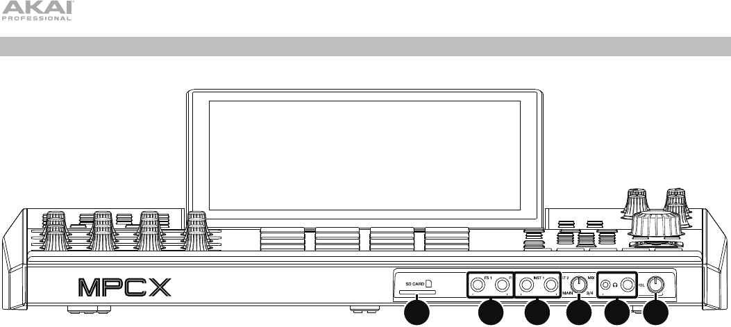
Front Panel
123456
1. SD Card Slot: Insert a standard SD or SDHC card into this slot to access its files directly using MPC X.
2. Footswitch Inputs (FS 1/2) (1/4” / 6.35 mm): Connect optional 1/4” (6.35 mm) TS footswitches to these inputs.
3. Instrument Inputs (Inst 1/2) (1/4” / 6.35 mm): Use standard 1/4” (6.35 mm) TS cables to connect these inputs to
audio sources (guitars, synthesizer, drum machine, etc.). To use each of these inputs, set the corresponding
Rear/Front switch (below the Gain 1/2 knob on the top panel) to Front.
4. Mix Knob: Turn this knob to adjust the balance between the Main and 3/4 signals in your headphones. Main is
the signal sent from the Main L/R outputs. 3/4 is the signal sent from the Outputs 3/4.
5. Headphone Outputs (1/8” or 1/4” / 3.5 mm or 6.35 mm): Connect your headphones (not included) to either or
both of these standard stereo outputs. Use the Mix Knob to determine what signal is heard in the headphones.
6. Headphone Volume: Turn this knob to adjust the volume of the headphone outputs.
9
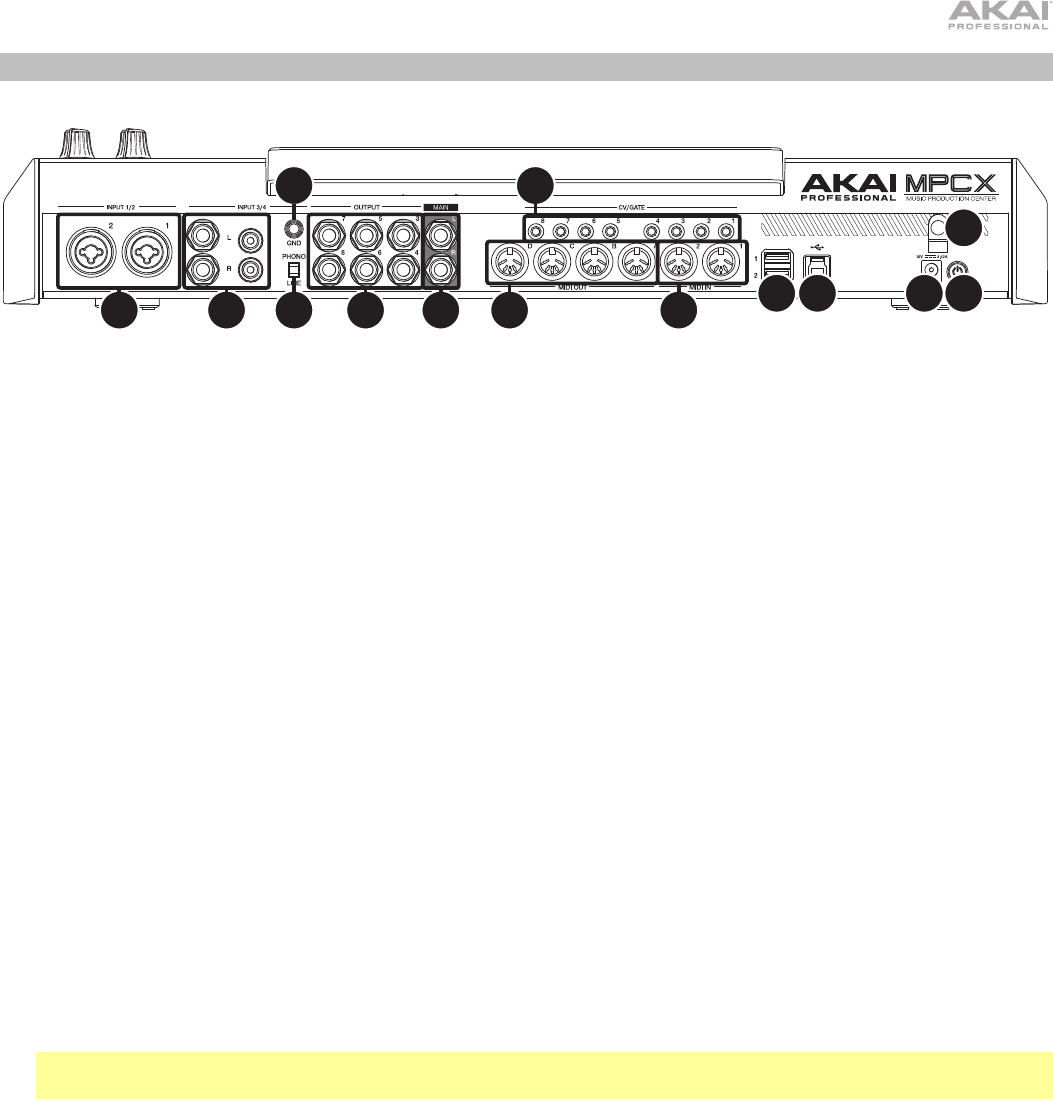
Rear Panel
1
2
3
4
5
678
9
10
11 12
13
14
1. Power Input: Connect the included power adapter (19 V, 3.42 A, center-positive) to this jack then into an
electrical outlet.
2. Power Adapter Restraint: Secure the power adapter cable to this restraint to prevent it from accidentally
unplugging.
3. Power Switch: Press this button to turn MPC X’s power on or off. While powered on, press and hold this button
for 5 seconds to force MPC X to power off (similar to a computer).
4. USB-B Port: Use the included USB cable to connect this high-retention-force USB port to an available USB port
on your computer. This connection allows MPC X to send and receive MIDI and audio data to and from the MPC
software on your computer.
5. USB-A Ports: Connect USB flash drives to these USB ports to access their files directly using MPC X.
6. Inputs 1/2 (XLR or 1/4” / 6.35 mm): Use standard XLR or 1/4” (6.35 mm) TRS cables to connect these inputs to
audio sources (microphone, mixer, synthesizer, etc.). To use each of these inputs, set the corresponding
Rear/Front switch (below the Gain 1/2 knob on the top panel) to Rear. Turn the Gain 1/2 knobs to set the input
level of each one.
7. Inputs 3/4 (1/4” / 6.35 mm or RCA): Use standard 1/4” (6.35 mm) TRS cables or stereo RCA cables to connect
these inputs to audio sources (mixer, turntable, synthesizer, etc.). To use the 1/4” (6.35 mm) inputs, set the
Phono/Line switch to Line. To use the RCA inputs, set the Phono/Line switch to Phono. Turn the 3/4 Rec Gain
knob to set their input levels.
8. Phono/Line Switch: Set this switch to the appropriate position, depending on which Input 3/4 connectors you
want to use. If you are using the 1/4” (6.35 mm) inputs, set this switch to Line. If you are using the RCA inputs,
set this switch to Phono to provide the additional amplification needed for phono-level signals.
9. Grounding Terminal: If you are sending a phono-level turntable signal to the Input 3/4 RCA connectors and are
hearing a low hum or buzz, it could mean that the turntable is not grounded. If the turntable has a grounding
wire, connect it to this terminal.
Note: Some turntables have a grounding wire built into the RCA connection and, therefore, nothing needs to be
connected to the grounding terminal.
10. Main L/R Outputs (1/4” / 6.35 mm): Use standard 1/4” (6.35 mm) TRS cables to connect these outputs to your
speaker system. The signal sent out of these outputs is the master mix. Turn the Master knob to set their
volume. To route a program to these outputs, set its routing to Out 1,2 in the Channel Mixer when the Mixer
field is set to Programs.
11. Outputs 3/4, 5/6, 7/8 (1/4” / 6.35 mm): Use standard 1/4” (6.35 mm) TRS cables to connect these outputs to an
external mixer. The signal sent from these outputs is full-volume (0 dB). To route a program to these outputs, set
its routing to Out 3,4, Out 5,6, or Out 7,8 in the Channel Mixer when the Mixer field is set to Programs.
12. MIDI In: Use a standard 5-pin MIDI cable to connect this input to the MIDI output of an optional external MIDI device.
13. MIDI Out: Use a standard 5-pin MIDI cable to connect this output to the MIDI input of an optional external MIDI device.
14. CV/Gate Out: Use standard 1/8” (3.5 mm) TS cables to connect these outputs to optional external sequencers.
MPC X will send control voltage (CV) and/or Gate data over this connection.
10
Operation
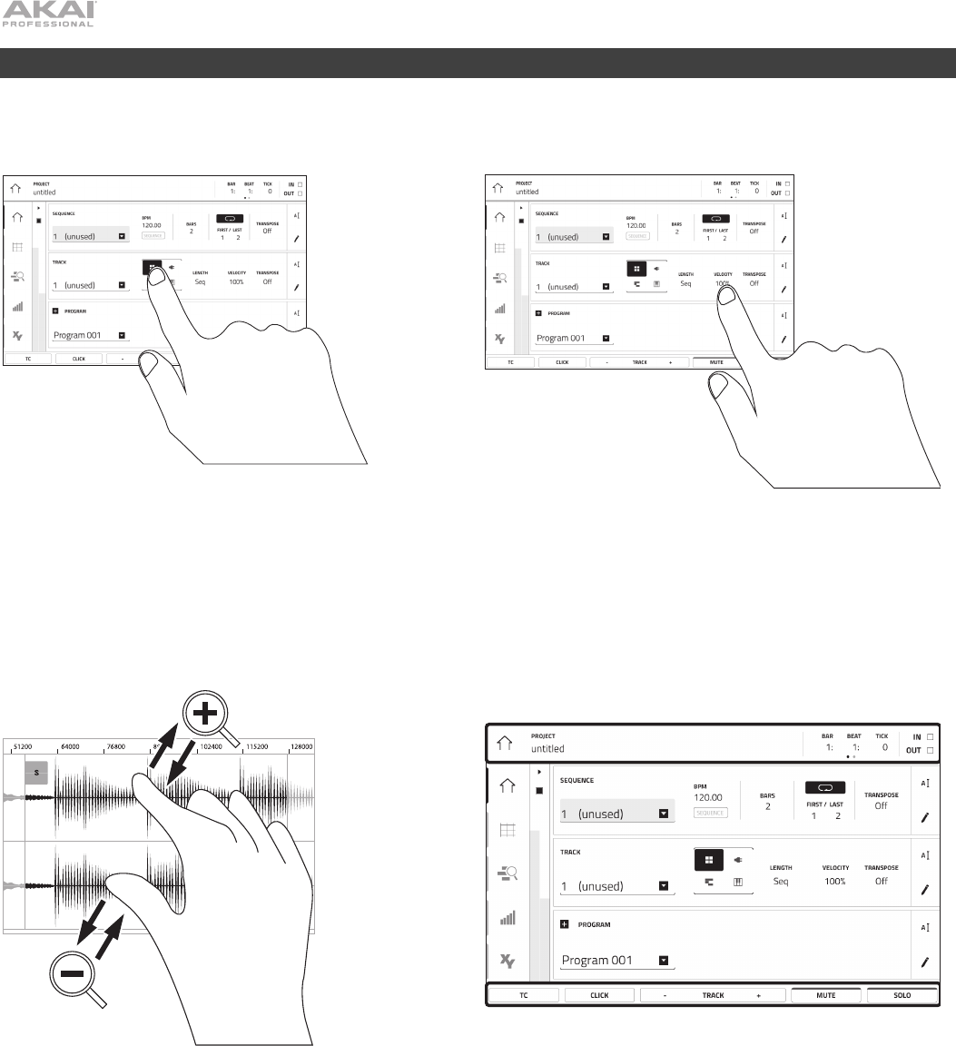
Here is some general information about how to use the MPC X display:
x2
Tap a button or option to select it. Use the Data Dial or
–/+ buttons to change its setting or value
Double-tap a button to access advanced editing
options. In some cases, this will show a numeric
keypad that you can use to enter a value (an alternative
to the Data Dial or –/+ buttons). Tap the upper-left part
of the display to return to the previous view.
Spread two fingers to zoom in (into a section of a
waveform, for example). Pinch two fingers to zoom out.
The upper edge of the display shows the toolbar, which
contains information about the current view (often the
name of the current track, sequence, audio pointe
r
position, etc.). Tap an item to select it.
The lower edge of the display shows various buttons
that you can use in the current view. Tap a button to
press it.
To return to a previous view, either tap outside of the
window currently in the display or tap the left arrow ()
in the upper-left part of the display.

11
Technical Specifications
Pads (16) velocity- and pressure-sensitive pads, RGB-backlit
(8) banks accessible via Pad Bank buttons
Knobs (16) 360° touch-sensitive Q-Link knobs for parameter adjustment
(1) 360° encoder for display navigation and selection via push
(7) 270° knobs for gain, mix & level adjustment
Buttons (63) dedicated-function buttons
Display 10.1” / 257 mm (diagonal)
8.5” x 5.5” / 216 x 139 mm (width x height)
Full-color LED-backlit display with touch interface
CPU Processor
1.8 GHz quad-core
A
RM®Cortex®
A
17 processo
r
RAM 2 GB
Storage
16 GB (user storage, 10 GB pre-installed content), 4 GB (MPC operating system)
Connections (2) XLR+1/4” (6.35 mm) TRS inputs (Input 1/2)
(2) 1/4” (6.35 mm) TRS inputs (Input 3/4: 1 stereo pair)
(2) 1/4” (6.35 mm) TS instrument inputs (Inst 1/2)
(2) RCA inputs (Input 3/4: 1 stereo pair, phono- or line-level)
(2) 1/4” (6.35 mm) TS footswitch inputs (FS 1/2)
(2) 5-pin MIDI inputs
(8) 1/4” (6.35 mm) TRS outputs (Main L/R, Outputs 3/4–7/8: 4 stereo pairs)
(4) 5-pin MIDI outputs
(8) 1/8” (3.5 mm) CV/Gate outputs
(1) 1/4” (6.35 mm) stereo headphone output
(1) 1/8” (3.5 mm) stereo headphone output
(2) USB Type-A ports
(1) USB Type-B port
(1) SD card slot
(1) power adapter input
Power via power adapter (19 V, 3.42 A, center-positive, included)
Dimensions
(width x depth x height)
19.9” x 16.7” x 3.4”
/
50.5 x 42.4 x 8.7 cm (display flat)
19.9” x 15.3” x 8.4” / 50.5 x 38.8 x 21.4 cm (display upright)
Weight 12.57 lbs.
5.66 kg
Specifications are subject to change without notice.
Trademarks & Licenses
Akai Professional and MPC are trademarks of inMusic Brands, Inc., registered in the U.S. and other countries.
ARM and Cortex are registered trademarks of ARM Limited (or its subsidiaries) in the EU and/or elsewhere. All rights reserved.
SD and SDHC are registered trademarks of SD-3C, LLC.
All other product names, company names, trademarks, or trade names are those of their respective owners.

Compliance Draft 1.0