INOVA Geophysical Equipment FSU2 Data Collection Device utilizing a radio channel for command and control User Manual Field Operations
INOVA Geophysical Equipment Limited Data Collection Device utilizing a radio channel for command and control Field Operations
User Manual

Draft Uncontrolled Release
FireFly®
Field Operations
Quick Reference Guide
Release 2.0
1018-010030C
Rev. PC8
July 2008
Draft Uncontrolled Release
ION Geophysical Corporation
12300 Parc Crest Drive
Stafford, Texas 77477-2416 USA
Tel +1.281.552.3002
Fax +1.281.879.3626
www.iongeo.com
Copyright © 2008 ION Geophysical Corporation. All rights reserved.
No part of this publication may be reproduced, transmitted, transcribed, stored in a retrieval system, or translated into any language
or computer language in any format or by any means, electronic, mechanical, magnetic, optical, chemical, manual, or otherwise,
without prior written permission of ION Geophysical Corporation. Copyright violators also may be subject to civil penalties.
ION Geophysical makes no warranties as to the accuracy, validity, or fitness for use or application of the contents of this document.
ION Geophysical reserves the right to revise the information in this document at any time without notice. Although an attempt has
been made to ensure the accuracy of the following material, no responsibility is assumed by ION for any use, or for any conse-
quences resulting from any use, of the information contained herein. No guarantee of suitability for any purpose is offered or
implied.
FireFly® is a registered trademark of ION Geophysical Corp.; SCORPION® is a registered trademark of ION Geophysical Corp..
ION has attempted, throughout this document, to distinguish proprietary trademarks from descriptive terms by following the capital-
ization style used by the manufacturer. All brand names and product names used in this document are trade names, service marks,
trademarks, or registered trademarks of their respective owners.
Print date: November, 2007
Original publication date: November, 2007
PDF part number: 1018-010030-0001PC7
To order printed copies of this document, please reference the following part number: 1018-010030-0002C
FireFly Field Operations Quick Reference Guide 1
Draft Uncontrolled Release
Contents
Loading the Equipment......................................................................................................................2
Equipment Layout/Distribution .........................................................................................................3
Changing the External Battery...........................................................................................................5
Field Shooting for Dynamite..............................................................................................................6
FSU/SVSM Pickup ............................................................................................................................8
FCC ID: MCV-FSU2
This device complies with Part 15 of the FCC Rules. Operation is subject to the following two conditions:
(1) this device may not cause interference, and (2) this device must accept any interference, including
interference that may cause undesired operation of the device.
FCC Modification Rule for User Manuals:
Changes or modifications not expressly approved by the party responsible for compliance could void the
user’s authority to operate the equipment.
Warning RF Exposure Compliance
The antenna(s) used for this transmitter must be installed to provide a separation distance of at least 60 cm
from all persons and must not be co-located or operating in conjunction with any other antenna or
transmitter. Users and installers must be provided with antenna installation instructions and transmitter
operating conditions for satisfying RF exposure compliance.

FireFly Field Operations Quick Reference Guide 2
Draft Uncontrolled Release
Loading the Equipment
To load the equipment onto the hasps, perform
the following tasks:
1. Load the FSUs and SVSMs onto the hasp
2. Load the external batteries onto the hasp
Equipment and Time
•A crew of one
•Empty field hasp
•6 FSUs (Field Station Units)
•6 SVSMs
•6 charged External Batteries
•Holding tube for antennas
Time: 15 minutes (when performed by single
crew member)
TASK: Loading the Hasp
1. Connect the SVSM to the FSU:
a. Connect the sensor connector to the FSU
cable connector.
b. Wrap the dustcap wires around the
connector and connect the dustcaps
together.
2. Load the antennas into the holding tubes.
3. Connect and load the remaining SVSMs and
FSUs for this hasp until all six FSUs, SVSMs,
Batteries and the holding tube have been
loaded.
4. Load the equipment onto the hasp by
stringing the hasp through the molded loops
on the FSU, SVSM and the batteries.
FireFly Field Operations Quick Reference Guide 3
Draft Uncontrolled Release
Equipment Layout/Distribution
For incremental equipment layout distribution:
•Set up the equipment at the receiver location
•Navigate from receiver to receiver, dropping
the hasp at every sixth receiver
•Navigate from hasp to hasp
Equipment and Crew
A crew of three people:
•Line Boss (LB): carries NavTool on
alignment tool and antennas
•Helper 1 (H1): Carries drill
•Helper 2 (H2) carries two hasps of gear
Note Crew size can changed depending on the
operations layout. The minimum crew will be two.
TASK: Lay Out And Distribute Equipment
1. Locate hasp (LB).
Use Navtool to locate the hasp dropped by the
helicopter or mule, and move hasp to the
closest station location.
2. Unload equipment (H1 & H2).
• Secure the helicopter-ground assembly at
the first station, and unload the first set of
the FSU/SVSM units from hasp.
• Attach the antenna to the antenna mount.
• Plug the SVSM cable into the FSU.
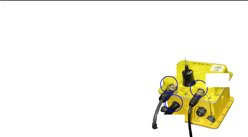
• Plug the external battery into the FSU as
shown in Figure 1-1 and wait 30 seconds.
Figure 1-1. FSU connections
SVSM
Connection
on FSU
Battery
Connection
on FSU
Connection
on External
Battery
FireFly Field Operations Quick Reference Guide 4
Draft Uncontrolled Release
3. Place FSU and SVSM (LB, H1&H2).
• Using NavTool, determine the proper
location for SVSM (LB).
• Power on the FSU by swiping with magnet.
• Auger a hole for the VectorSeis sensor
(SVSM) and place the SVSM securely in
the hole.
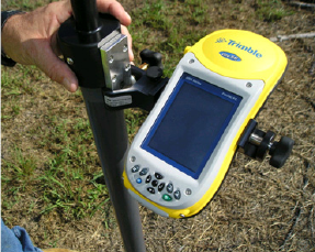
4. Take alignment readings (LB).
• Keeping the NavTool attached to the
Alignment pole, place the Alignment pole
over the SVSM to get a reading.
Figure 1-2. NavTool on Alignment Pole
• Take a GPS and Compass reading with
NavTool and transmit the readings to FSU.
5. Move to the next station (LB, H1 & H2).
• Pick up hasp and drill and move to the next
station.
• (LB only) Navigate to the next location
using NavTool.
6. Unload equipment (H1 & H2).
• Unload the next sets of the FSU/SVSM
units from hasp and place the units at the
station location.
• Plug the antenna, SVSM cable, and the
external battery into the FSU. Wait 30
seconds after plugging battery into FSU.
7. Repeat step 3 and step 4 for all remaining
in the hasp (LB, H1 & H2).
8. Move to final station in pack (LB, H1 &
H2).
• Secure the empty hasp at final station that
station (H2).
• Use NavTool to take GPS reading for the
empty hasp position (LB).
9. Use NavTool to select next full hasp in the
field (LB) and repeat step 1 to step 9.
FireFly Field Operations Quick Reference Guide 5
Draft Uncontrolled Release
Changing the External Battery
You can change out an external battery in the
field.
Crew and Equipment
•A crew of two using the buddy system
•Charged external battery and cable
•NavTool
•Magnet
•Hasp (to hold external battery)
Time: 15 minutes (when performed by single
crew member)
1. Navigate to position for changing battery.
2. Unplug the external battery from the FSU.
3. Plug the new battery into the FSU. The FSU
will reboot when the battery is attached.
4. If the FSU does not reboot, power on the FSU
by swiping with magnet.
5. Verify that the NavTool connects to the FSU.
6. Place discharged battery on hasp.
The discharged battery should be recharged
and checked at the Battery Charging Module.
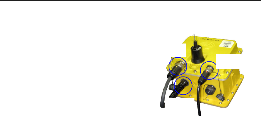
Figure 1-3. FSU connections
SVSM
Connection
on FSU
Battery
Connection
on FSU
Connection
on External
Battery

FireFly Field Operations Quick Reference Guide 6
Draft Uncontrolled Release
Field Shooting for Dynamite
Crew and Equipment
A crew of two:
•Shooter (S): Pelton Shot Pro® II firing pack
(includes all Pelton equipment), digital
compass mounted to firing pack, NavTool,
and radio
•Helper 1 (H1): Backpack with water,
miscellaneous tools, and radio
Note The total number of shooting crews will vary
depending on the daily production targets, resources
and equipment. The communication collision
management allows shooting crews to operate
independently and in parallel so a higher number of
total crews can operate simultaneously, compared to
traditional dynamite shooting operations.
TASK: Shooting
1. Navigate to the source position using
NavTool and take a GPS reading (S & H1).
2. Prepare for shooting (S & H1).
• (H1 only) Connect the firing line to the cap
lead at the drill hole.
• Stretch out the firing line and the geophone
line while moving a safe distance (typically
a minimum of 100 feet) from this source
position in the direction of the next source
position, if possible.
• Place the uphole geophone beside the
shooting position so that the uphole time of
the shot can be measured.
• Remove the Shot Pro backpack and place it
upright on the ground. Place NavTool on
top of shooting pack (it shows status during
shooting and is used for data entry).
3. Prepare for shooting (S).
• Press the READY button and wait for the
ARM notification from the recorder.
• When the ARM notification is received
(green LEDs flash on the Shot Pro front
panel and the NavTool displays a
message), press and hold the two buttons
on the Shot Pro to charge the firing voltage
and arm the Shot Pro. Continue holding the
FireFly Field Operations Quick Reference Guide 7
Draft Uncontrolled Release
buttons until the FIRE command is
received.
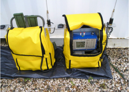
Figure 1-4. Pelton ShotPro
Warning At this point, the shooter has control over the
shot detonating. If the area around the shot hole is not
clear, the shooter can release the buttons to abort the
shot.
4. Take the Shot (S).
• When the FIRE command is received and
the shot is detonated, release the charge
buttons.
• Select the shot status (good, misfire, or
blow out) on the NavTool before moving to
the next shot point.
• If the shot was a misfire, retry the shot.
You do not need to radio the mis-fire into
the recorder over voice radio. The system
automatically puts the shooter back into the
shooting queue to try the shot again.
5. Clean up and navigate to next position
(S&H1)
• (H1) Clean up the detonated shot hole.
• (S) Put the Shot Pro backpack on and use
NavTool to go to the next position.
6. Repeat step 2 through step 5 for all assigned
source positions for the day.
Note If the Helper (H1) is lagging due to cleanup
duties, the Shooter (S) should navigate to the next
source position alone and connect the firing line to the
cap lead himself.

FireFly Field Operations Quick Reference Guide 8
Draft Uncontrolled Release
FSU/SVSM Pickup
Equipment and Crew
The pickup crew will be the same size as the
deployment crew.
•Line Boss (LB): carries NavTool on
alignment tool and hasp.
•Helper 1 (H1): Carries extraction tool and
miscellaneous equipment.
Note Crew size can changed depending on the
operations layout. The minimum crew will be two.:
TASK: Pick Up Equipment
1. Locate hasp (LB, H1 & H2).
• Use NavTool to navigate to empty hasp
(LB).
• Pick up hasp and open it (H1).
2. Navigate to first station (LB, H1 & H2).
3. Pick up FSU, SVSM, and battery and put
into hasp (LB, H1 & H2).
• (LB only) Verify the FSU ID by tapping
the appropriate button: Picked up, Other
FSU Picked Up, or No FSU Picked Up.
• (H1) Retrieve SVSM, using extraction tool
if necessary.
• (H2) Gather the FSU, SVSM, and external
battery and place them onto hasp.
4. Navigate to next position and repeat step 3
(LB, H1 & H2).
5. Move to final station on a hasp (LB, H1 &
H2).
• Ensure that all ground assembly equipment
is on the hasp.
• Secure the hasp, place it into the helibag,
and attach the helicopter lanyard to it.
• Use NavTool to take GPS reading for the
helibag (LB).
6. Use NavTool to select next full hasp in the
field (LB) and repeat step 1 to step 5.

www.iongeo.com
12300 Parc Crest Drive Tel + 1 281 552 3002
Stafford, TX 77477 USA Fax + 1 281 879 3626