INTO TECH LIVE120 DVR BOARD User Manual users manual 1
INTO-TECH Inc. DVR BOARD users manual 1
Contents
- 1. users manual 1
- 2. users manual 2
users manual 1

Contents
ⅠⅠInstallation Manual
1. Hardware Installation
2. Software Installation
ⅡⅡUser Manual
3. User Manual- Server
01. Main Program
02. Search Program
03. AVI Backup Manager
04. Backup Manager
4. User Manual- Client
01. NetClient Program
02. WebClient Program
※※Annex
Annex 1. I/O Device
Annex 2. Dynamic IP
Annex 3. IP Router
4
11.. HHaarrddwwaarree IInnssttaallllaattiioonn
Please check contents before installation: DVR Board, Extension
Cable, Audio & PTZ Installation, etc., if you are missing any parts
please contact your local dealer.
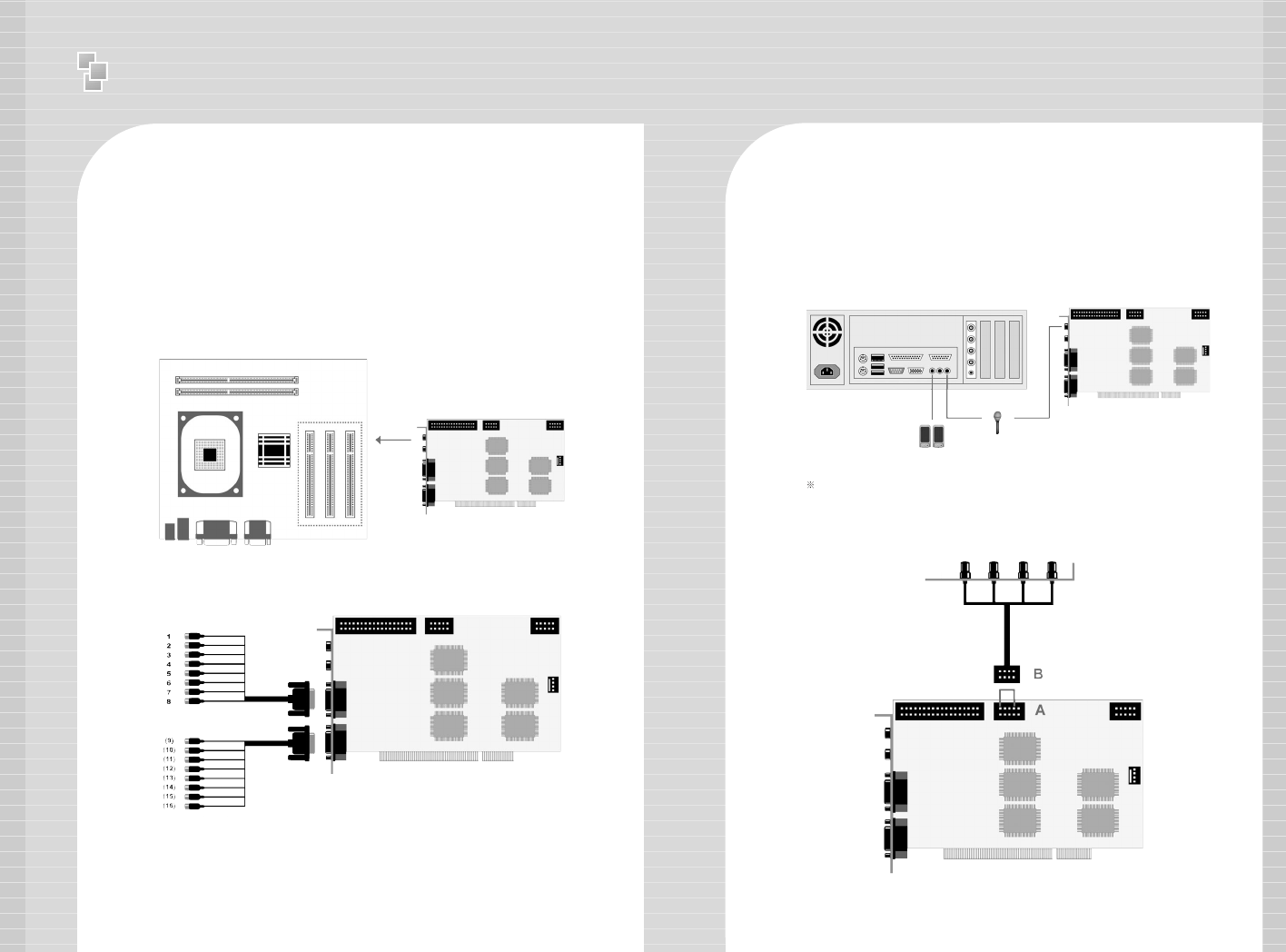
1. DVR Board & Extension Cable Installation
1-1. Insert the DVR Board to an empty PCI Slot in DVR PC.
1-2. Use Extension Cable to connect cameras.
Either connect the MIC to Audio IN port of DVR Board OR Mainboard MIC port.
2. DVR Audio Installation
2-1. Prepare DVR PC and MIC.
2-2. Connect the MIC to the Mainboard MIC Port of DVR PC OR
the Audio IN port on DVR Board. Please connect the Speaker to
the back panel of DVR PC.
<Mainboard>
<Extension Cable-1>
<Extension Cable-2>
<DVR Board>
<DVR System Back Panel>
<DVR Board>
<Speaker>
<MIC>
<4CH>
<H DVR Board>
- H Board: Connect the 4CH MIC(B) to DVR Board(A) starting
from the left.
<DVR Board>
5
Ⅰ
Installation manual - Hardware Installation
Ⅰ
Installation manual - Hardware Installation
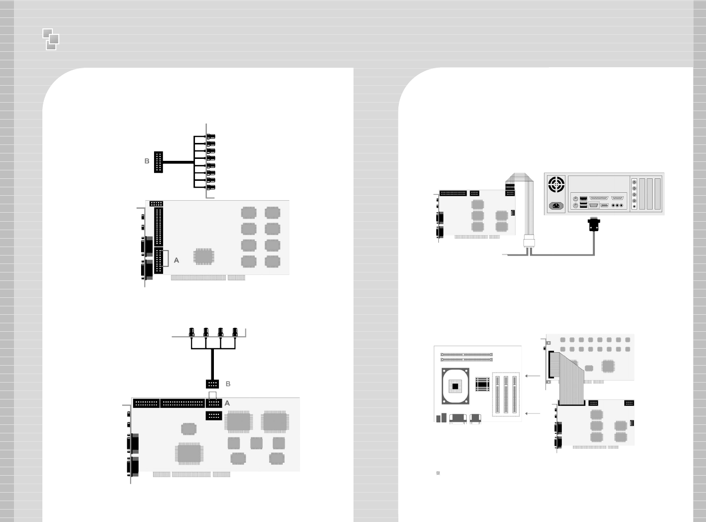
4. Real Display(RD) Board Installation
4-1.
Insert the Real Display Board into an empty PCI Slot in DVR PC.
4-2. Use Cable to connect Real Display Board with DVR Board.
Real Display Board cannot be used alone, it must be used with S, H, HPLUS
DVR Boards.
67
A
B
3. P/T/Z Installation
3-1. P/T/Z Cable
[A] Cable : Connect to COM port of DVR PC
[B] Cable : Connect to DVR Board
[C] Cable : Connect to Receiver Cable
- HP Board: Connect the 8CH MIC(B) to DVR Board(A) starting
from the top.
- RC Board: Connect the 4CH MIC(B) to DVR Board(A) starting
from the left.
C
<8CH>
<HP DVR Board>
<4CH>
<RC DVR Board>
<Mainboard>
<RD Board>
<DVR Board>
<DVR System>
<DVR Board>
B
A
<P/T/Z Cable>
89
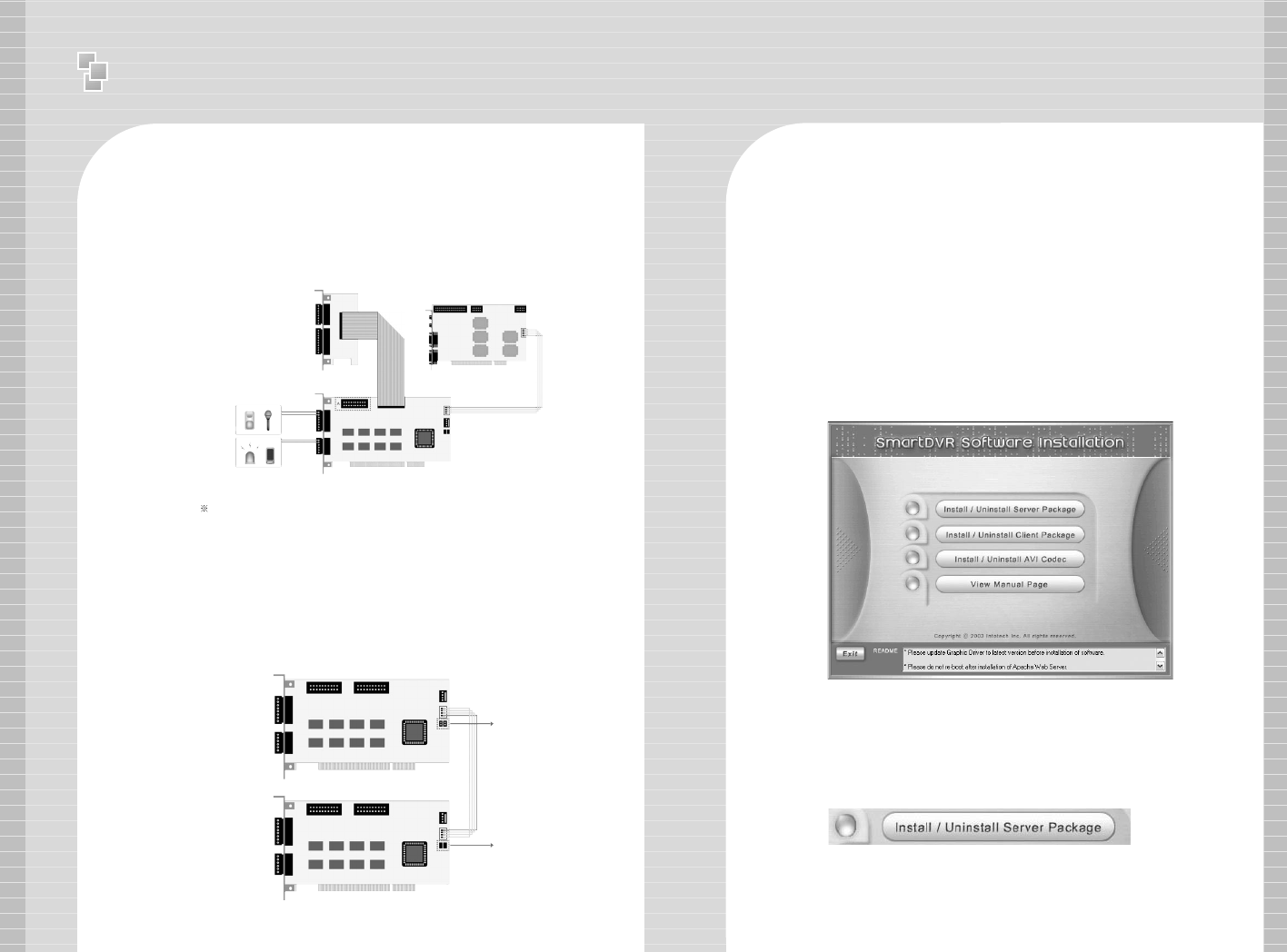
To use 16 port In/Out,
A : Slave Board must remove jumper.
B : Master Board must install jumper.
< 16 port In/Out Connection>
5. I/O Board Installation
5-1. Prepare Sensor, Alarm, I/O Board and I/O Extension Board for I/O
Board Installation.
A : Industrial Case System can use In/Out port separately when additional
Back Panel is available.
< 8 port In/Out Connection>
I/O Extension Board <DVR Board>
<I/O Board>
<I/O Slave Board>
<I/O Master Board>
4CH Input
3CH Output
A
A
B
4CH Input
5CH Output
Ⅰ
Installation manual - Software Installation
1. Software Installation
You can install SmartDVR Software by using SmartDVR Formula CD
or downloading from INTOTECH website, www.intotech.co.kr.
Software CD consists of Server Package (Main program, WebClient
program, Apache HTTP Server program), Client Package (NetClient
program) & AVI Codec. User Manual is also available from SW CD.
[Main Program Installation]
Insert SmartDVR Formula CD into CD-ROM drive or run
DvrSetup.exe file; the following installation screen will appear .
Click the icon below and Main Program installation will
automatically proceed.
Installation Step : Apache HTTP Server (Web Server) ->
WebClient -> SmartDVR Formula
Ⅰ
Installation manual - Software Installation
10 11
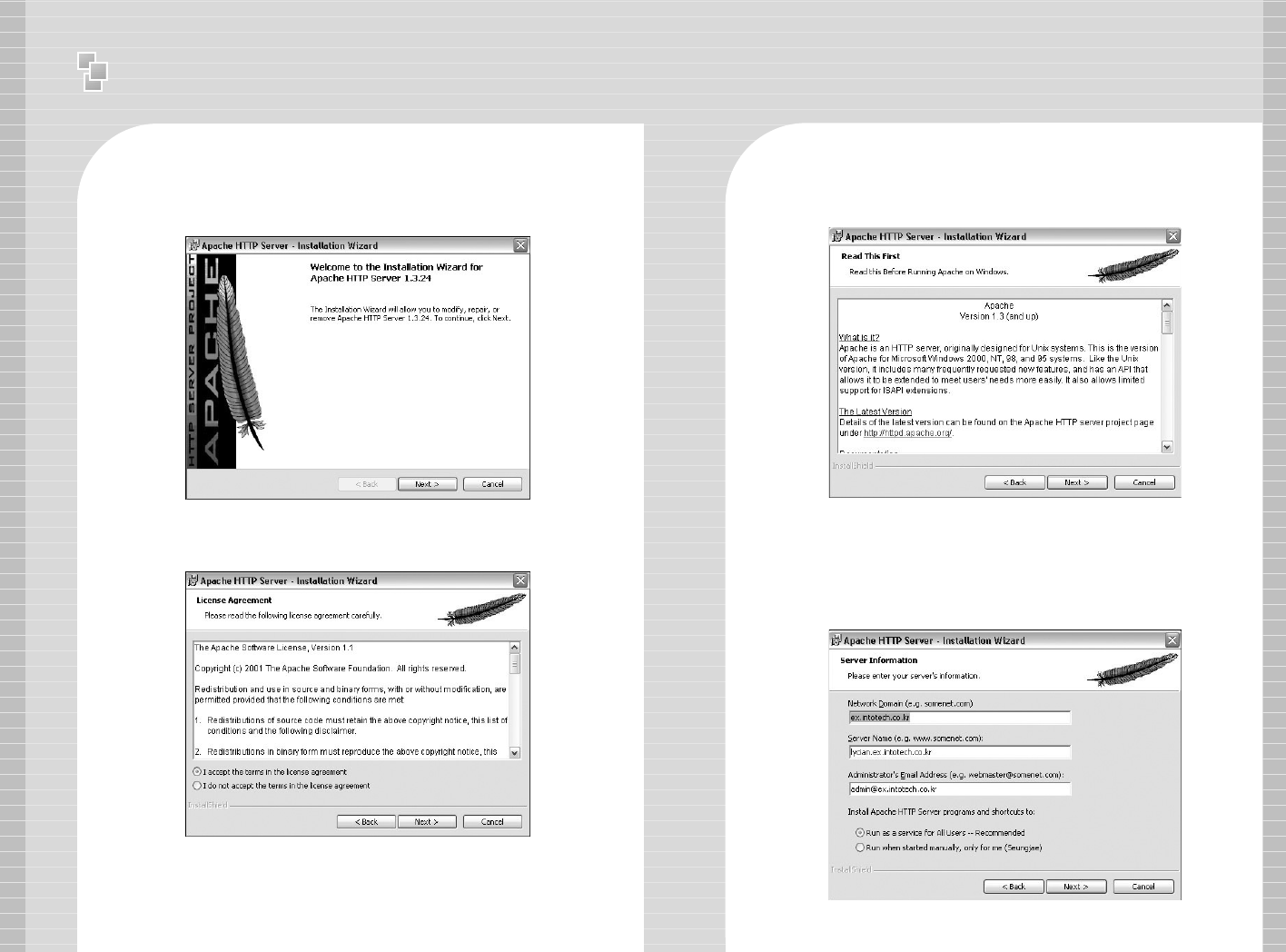
1. SmartDVR Apache HTTP Server (Web Server) Installation
1-1 Installation wizard tool will appear. Click [Next].
1-2 Read the License Agreement and if you agree to the
contents, select [I accept…] and click [Next].
1-3 Click [Next] after checking server information of Apache
HTTP Server.
1-4 Insert Network Domain, Server Name, Administrator’s
E-mail Address.
(This procedure is only a formality. In general cases, follow example)
Select [Run as a service for All Users – Recommended]
and click [Next].
Ⅰ
Installation manual - Software Installation
12 13
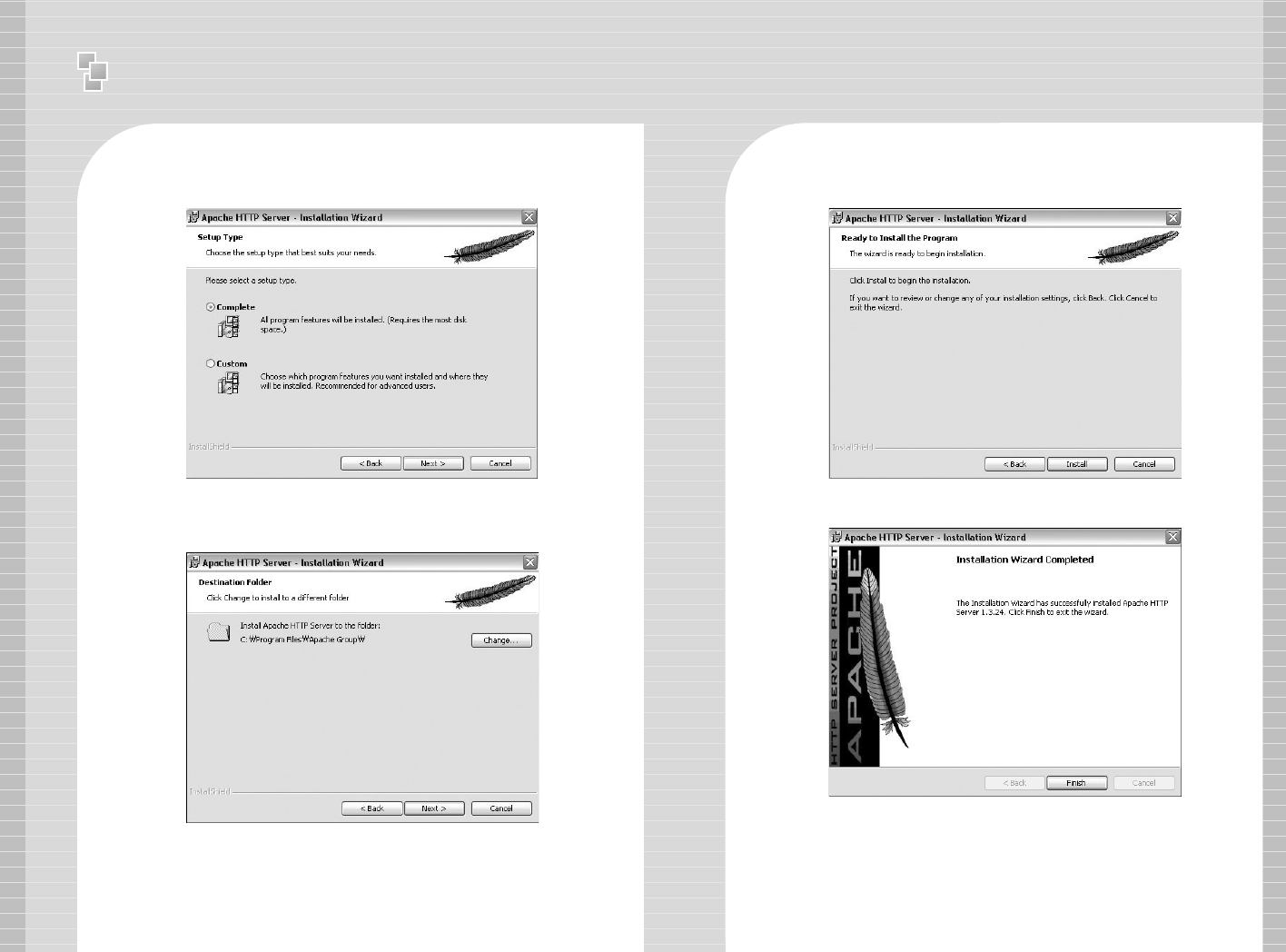
1-5 Select Setup Type as [Complete] and click [Next].
1-6 Click [Next] without change of setting. Note: Do not change
the directory!
1-7 After the setting is finished, click [Install] and start installation.
1-8 After the installation is done, click [Finish].
Ⅰ
Installation manual - Software Installation
14 15
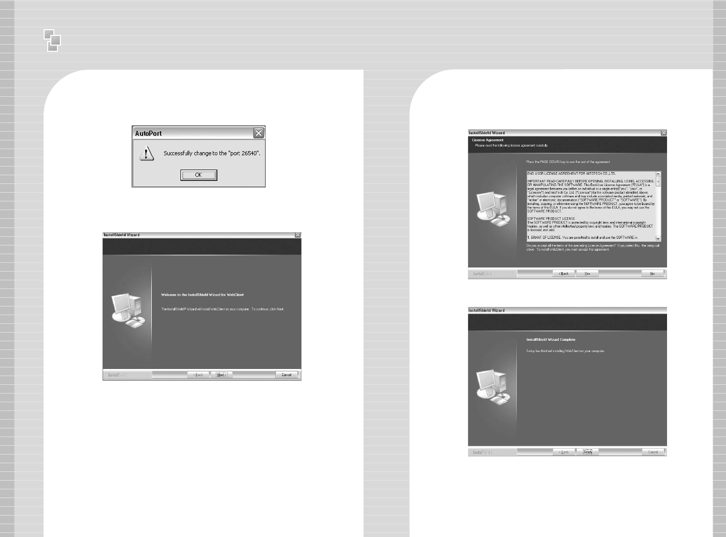
1-9 After the installation is finished, a message confirming the
change of the Server port of Apache will appear.
2 SmartDVR WebClient Installation
2-1 After the Installation Wizard Tool is appeared, click [Next].
2-2 Check the contents of License Agreement; if you agree to the
contents, click [Yes].
2-3 After the installation is done, click [Finish].
Ⅰ
Installation manual - Software Installation
16 17
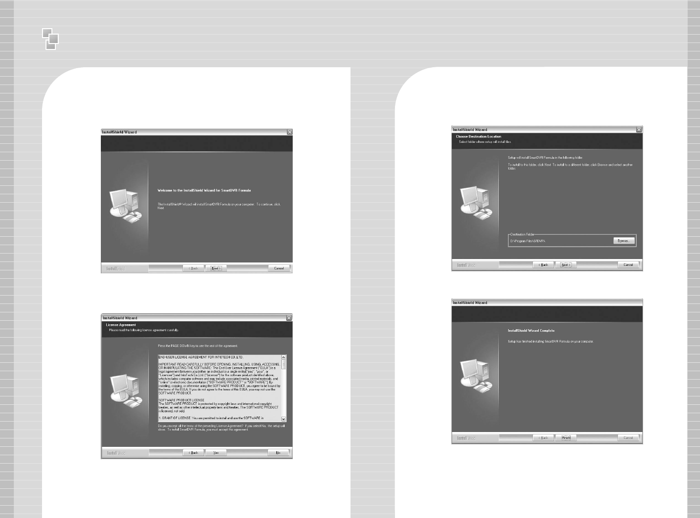
3 SmartDVR Formula Installation
3-1 After Installation Wizard Tool is appeared, Click [Next].
3-2 Check the details of License Agreement; if you agree to the
contents, click [Yes].
3-3 After choosing [Destination Folder] for installation, click
[Next].
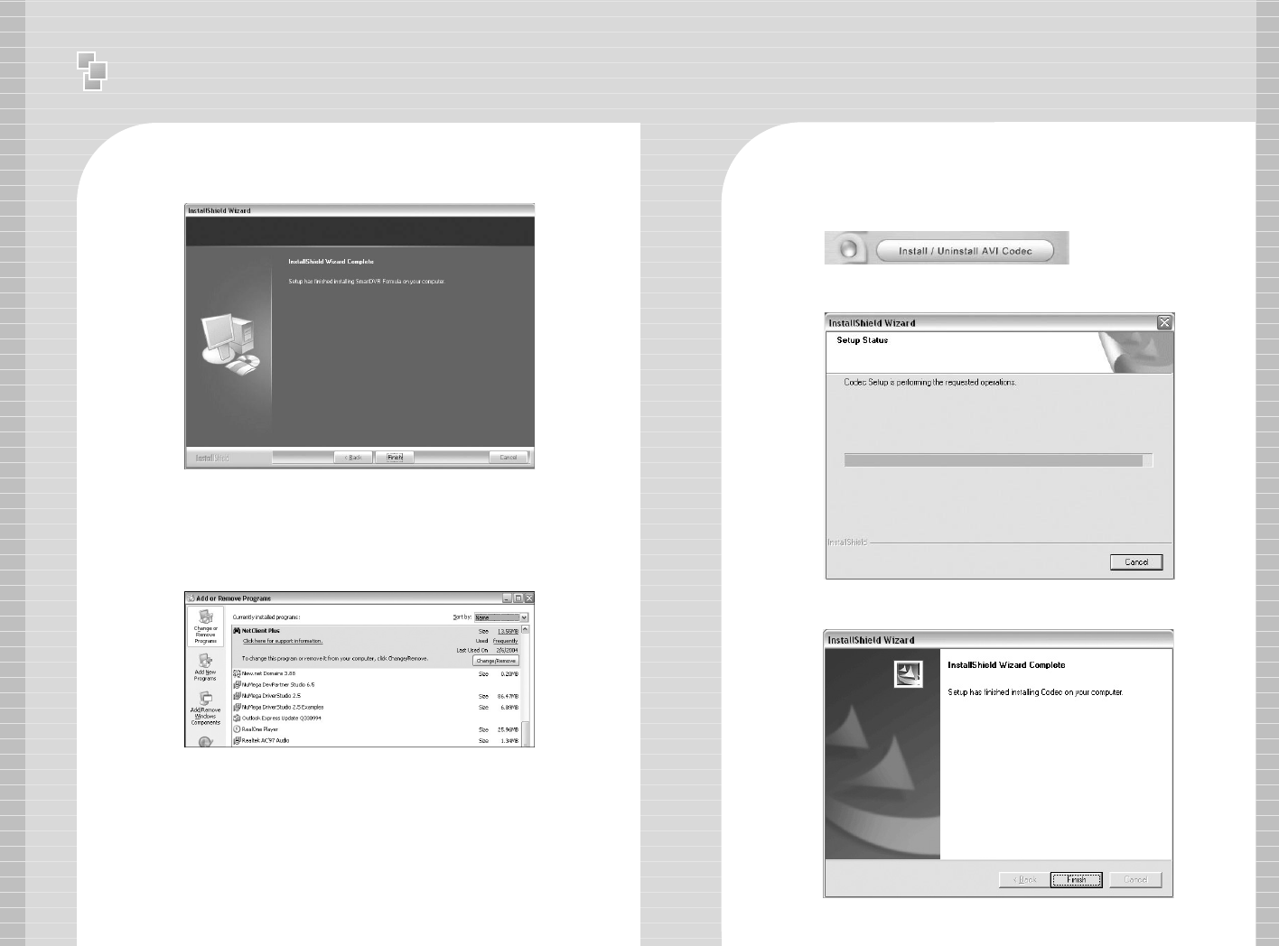
3-4 After the installation is done, click [Finish].
Ⅰ
Installation manual - Software Installation
19
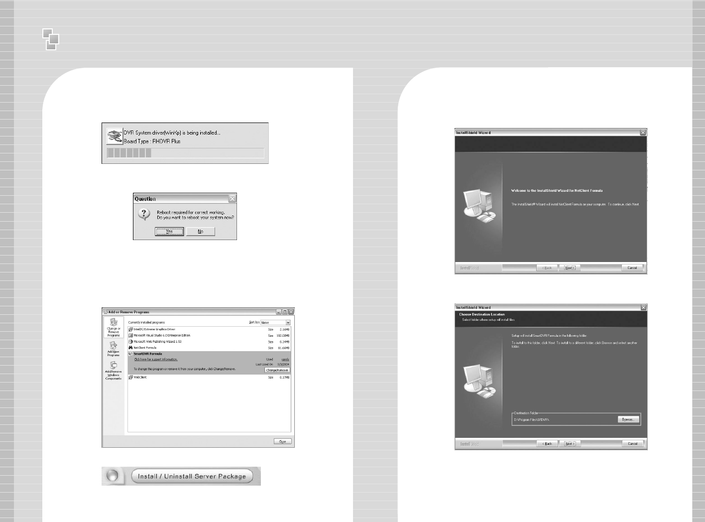
3-5 Driver Installation: Wizard automatically installs drivers
according to each board type.
3-6 Reboot PC after all the installation.
4. SmartDVR Formula Uninstallation
4-1 Goto [Start] – [Control panel] and click [Add/Remove
Program].
4-2 Select [SmartDVR Formula] and click [Change/Remove].
Click the icon below and NetClient Program installation will proceed.
5 NetClient Installation
5-1 After the Installation Wizard Tool is appeared, click [Next].
5-2 After choosing [Destination Folder] for installation, click [Next].
18
Ⅰ
Installation manual - Software Installation
20 21
5-3 After the installation is finished, click [Finish]
6 NetClient Uninstallation
6-1 Goto [Start] – [Control panel] and click [Add/Remove
Program].
6-2 Select [NetClient Plus] and click [Change/Remove].
AVI Codec Installation
Click the icon below and AVI Codec installation will proceed.
7-1 AVI Codec Installation diagram.
7-2 After the installation is finished, click [Finish].
22 23
Ⅱ
User Manual - Main Program
3 Main Program
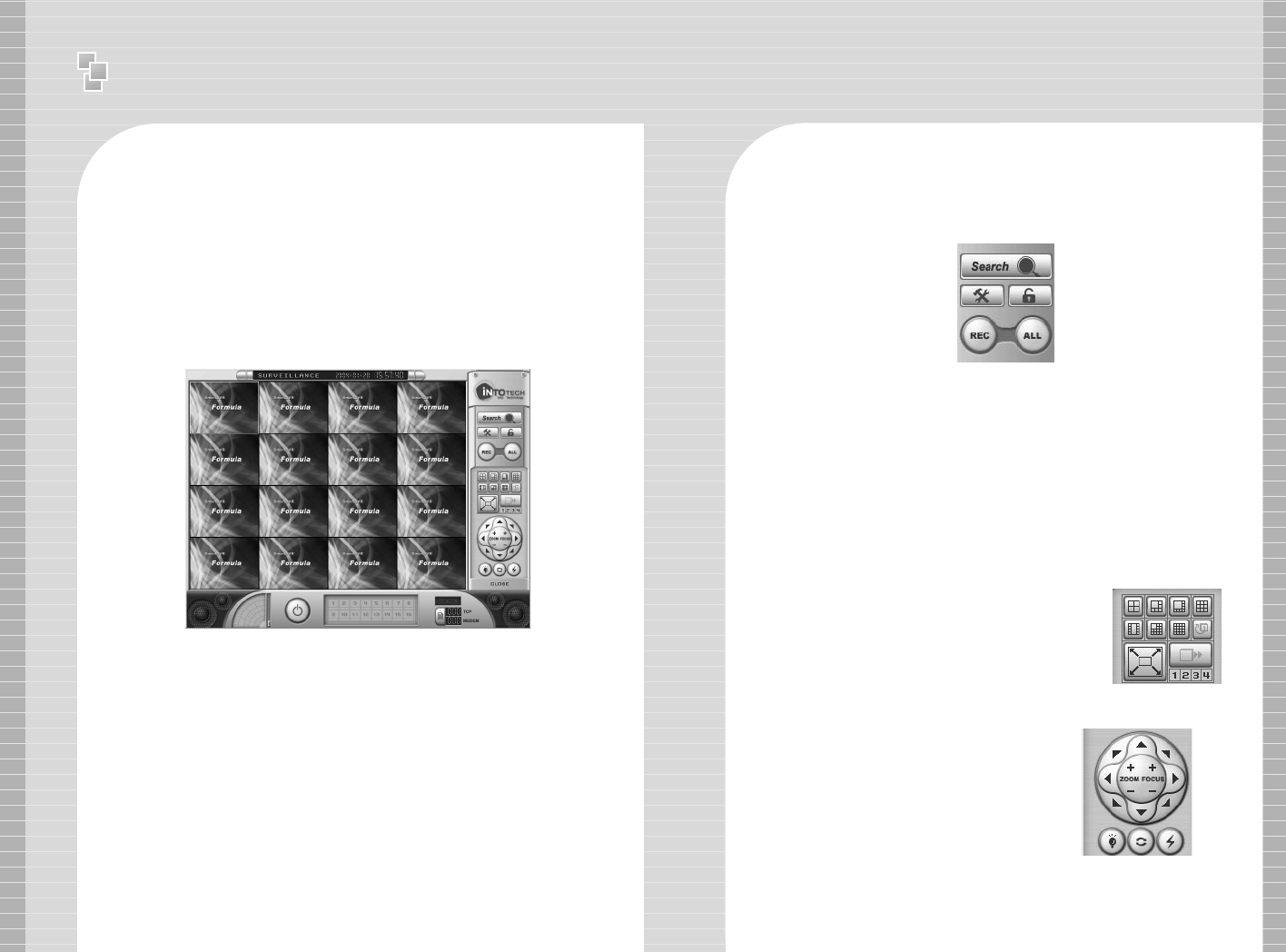
01. Main Program
Main Program enables users to monitor images through PC monitor.
The main program supports the following functions: record images,
search & playback images and control camera remotely. Image can
also be transmitted over the network to any remote site.
<Main Program>
1 : Control Panel
2 : Screen Partition Panel
3 : Pan/Tilt Control Panel
4 : Camera Selection Panel
5 : Audio Volume Control Bar
6 : Status Information Panel
1-1 Control Panel
Control Panel consists of the following icons: This enables users
to run search programs, manually record images and open
configuration window.
- Search Icon: Search Option.
- Configuration Icon: To change setup of program.
- Lock Icon: Supports password lock function for Server
security.
- Recording Icon and All Icon:
Record only certain channels – Enable users to manually
select certain channels for recording.
Record all channels – Click [All] icon and click [REC] icon
to record all channels.
→
Search Icon
→
Lock Icon
Configuration
←
Icon
Recording Icon
←→
All Icon
→
❶
→
❷
→
❸
❺
❹
❻
1-3 Pan/Tilt Control Panel
Use of Pan/Tilt Camera,
1.Select correct [Receiver] protocol from
[Configuration].
2. Select the channel which is connected
to Pan/Tilt camera.
3. Click various buttons from Pan/Tilt
Control Panel to control camera.
(Pan/Tilt/Zoom/Focus).
1-2 Screen Partition Panel
Support 7 kinds of various screen
partitions, full-screen and sequence
rotation display mode etc.
[Screen Partition Panel]
Pan/Tilt
&
Zoom/Focus
Button
24 25
1-5 Audio Volume Control Bar
If Audio input is configured from
[Configuration] - [General], audio volume
can be controlled from Audio Volume
Control Bar.
2 Configuration
Configuration Folder consists of [General], [Channel], [Store],
[Network], [Schedule], [Maintenance], [Event], [Receiver], [Video
Out] and [User Management] sub-panels. Configuration is used
for setting Resolution, Image Quality, Motion Detected Recording,
I/O, Schedule, Pan/Tilt Receiver Protocol, Network IP setup, etc.
Disk Full
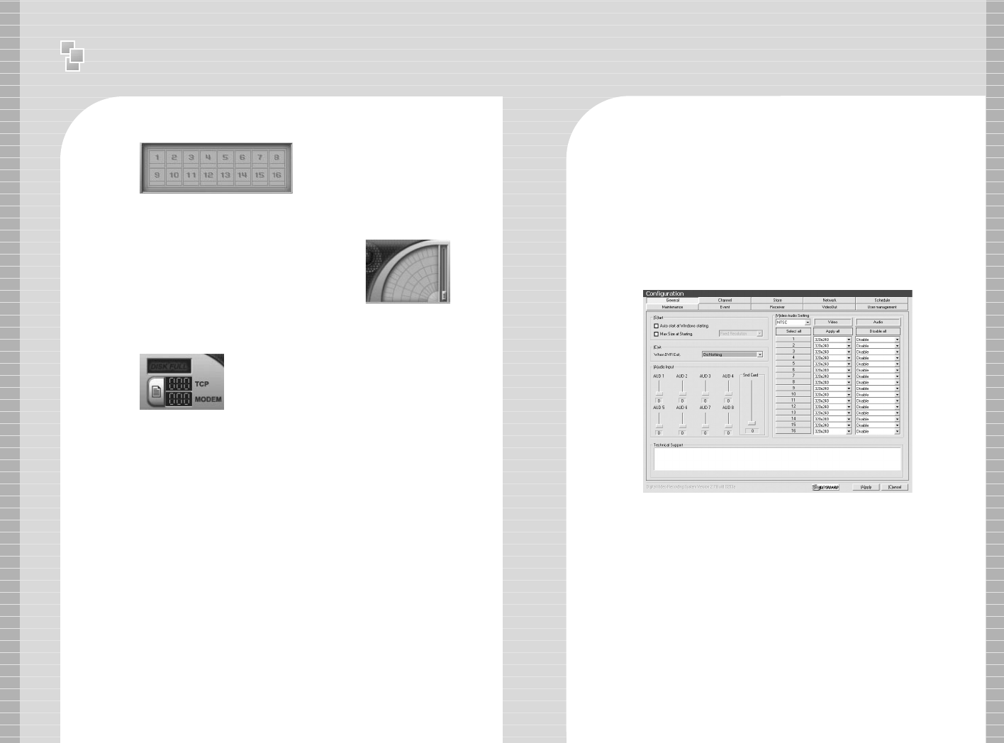
1-4 Camera Selection Panel
Click specific channel from Camera
Selection Panel to enlarge and view
images.
1-6 Status Information Panel
Indicates number of connection from
Internet( T C P ) & modem.
Disk Full will be indicated in red color
if there is no space left in HDD.
Start Section
- Auto Start: DVR program automatically executed when system
is turned on.
- Max size at starting: DVR Program is setup as the exact size of
monitor resolution to prevent display of other programs.
Exit Section
Option: Only DVR program shuts down after closing DVR
Program OR the complete system shuts down.
(Computer Power OFF).
Ⅱ
User Manual - Main Program
Internet(TCP) Conection CH No.
Modem Conection CH No.
1-1 General
Ⅱ
User Manual - Main Program
26 27
Audio Input
Setup the Gain of Audio Input.
- AUD1 ~ AUD8 is gain control for Audio Input from Capture Board. Set
the gain to minimum(0) when use of amplified mic. (e.g.: camera
built-in mic)
- Snd Card is audio volume control using Sound Card as output device.
Video/Audio Setup
- Setup Camera Input Type NTSC – Korea, USA, Japan, Australia(some
region), North Amercia(some region) etc.
PAL – Region excluding NTSC area(China, Europe, South America,
etc.)
- Channel Selection – Select channel for surveillance
- Resolution Setup – Image Resolution Setup(320X240 OR 640X480)
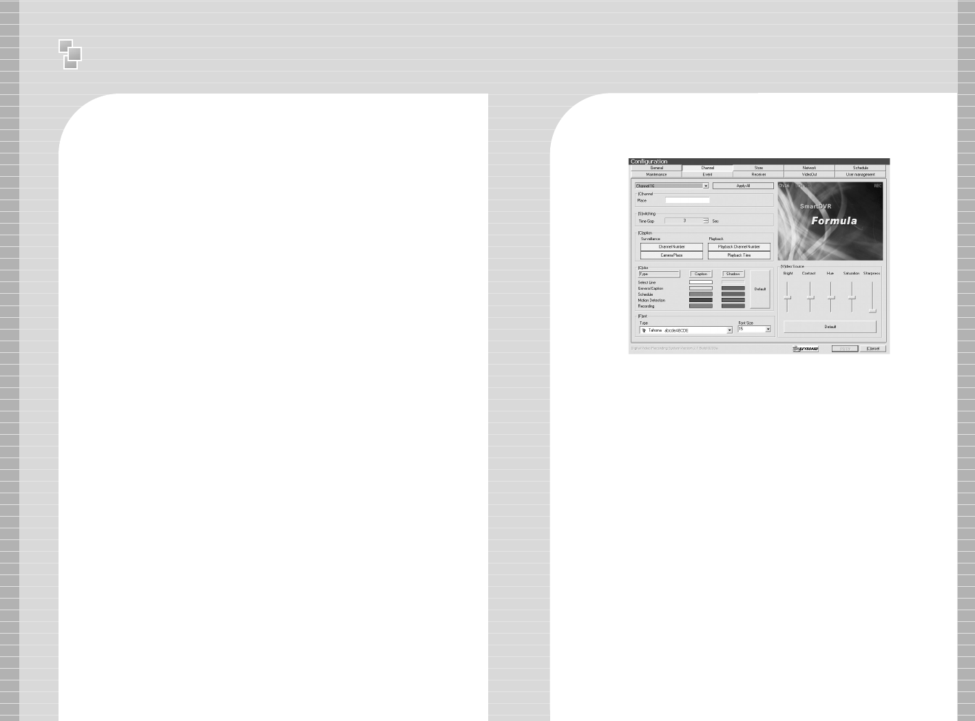
2 Channel
Channel(Caption) Input
Insert description of camera surveillance area
Caption Setup
- Surveillance Mode – Setup to indicate channel number
and camera surveillance area caption in Main Program.
- Search Mode – Setup to indicate channel number and
recorded time in Search Program.
※Caption Font and Color Setup – Setup caption font & color of
caption according to channel number, camera surveillance area,
recorded time etc.
※Video Source – Setup Brightness, Contrast, Hue, Saturation and
Sharpness.
Ⅱ
User Manual - Main Program
28 29
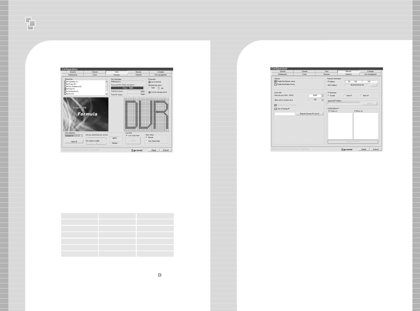
2 Store
※Store Disk – Indicates installed HDD Capacity.
Check(√) HDD to use as recording device
Notice) Recommend to disable C Drive(Operating System
installed) as recording device and use other drives(D, E, C).
※Overwrite – Setup overwrite to delete the oldest data when
free HDD is lesser than minimum free space allowed.
※Setup compression quality & max stored-frame per second.
Recording size of 1 frame according to image quality &
resolution is as followings:
Image Quality Resolution
Recording Size(KB)
Low 320X240 2.5
Low 640X480 6
Medium 320X240 3.7
Medium 640X480 10
High 320X240 5.0
High 640X480 15
※Watermark
Use Watermark to prevent image tampering of every recorded frame.
- Default: Watermark will be inserted as the word ‘ VR’.
- User Define Mark: Watermark will be inserted as user defined word
for easy identification or organization.
3 Network
※※Server Setup
- Enable the Network Server: Setup System to be used as Internet Server.
Server image can be viewed from remote Client Program OR Internet Web
Browser by using private line connected to internet.
- Enable the Modem Server:
Setup System to be used as PSTN Network Server.
Server image can be viewed from remote Client Program by using
modem connected through PSTN Network(Internet Web Browser not
supported.).
※※Network Information
System IP Address & MAC Address
- Direct connection to Server is possible from remote Client Program OR
Internet Web Browser when use of Fixed IP.
- Direct connection to Server is possible through DHS Server from remote
Client Program by using DHS Service provided by our company when use of
Dynamic IP.
※※User Limit
- IP Router User: Check [User of Sharing IP] if DVR System is connected to
internet using IP Router.
- Register Dynamic IP User ID: ID must be registered to use DHS Service when
use of Dynamic IP. Contact our company for more detailed information
regarding Dynamic IP.
Ⅱ
User Manual - Main Program
30 31
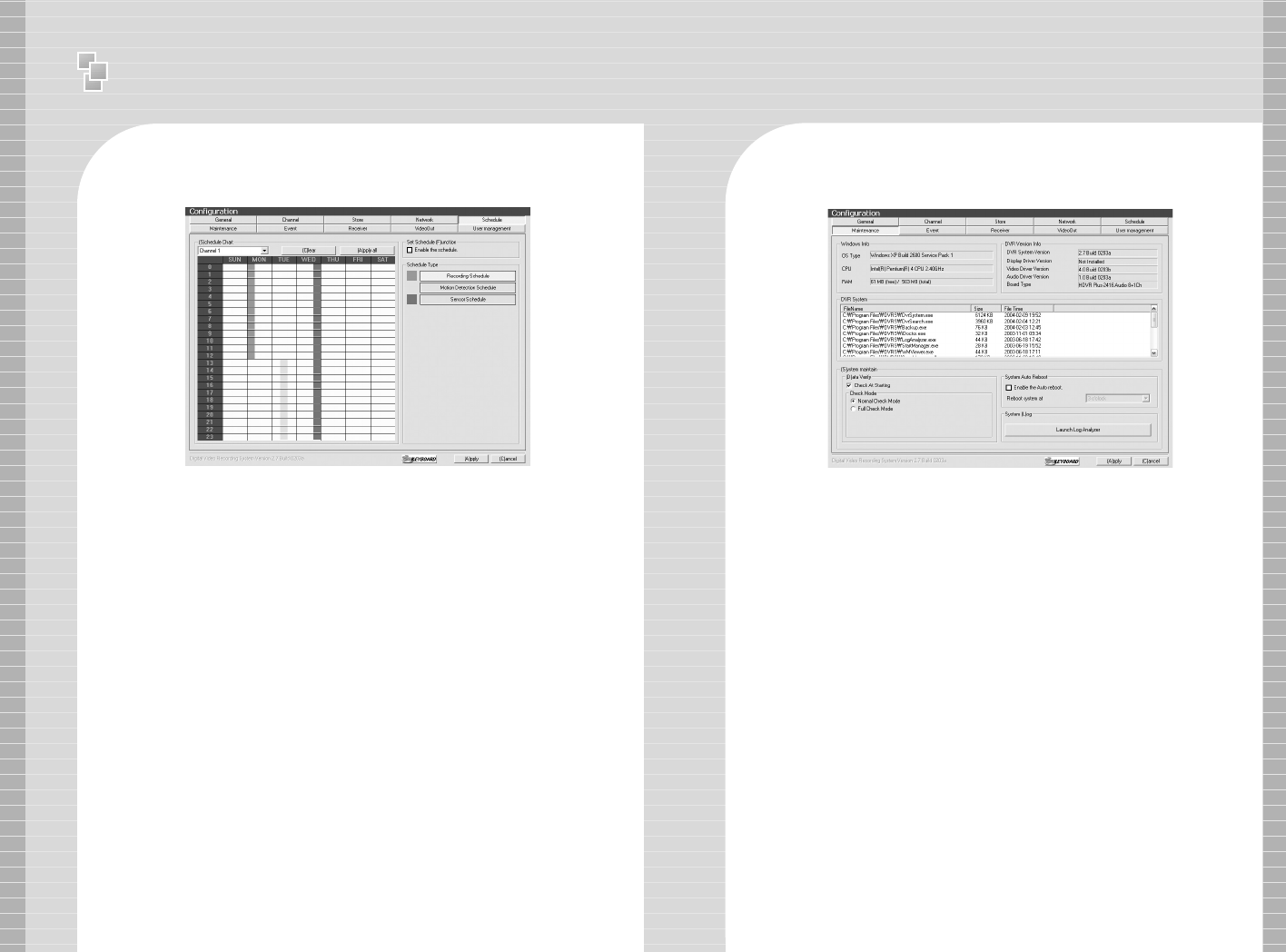
4 Schedule
Recording Modes: Full Recording, Motion Detected
Recording, Sensor Recording is possible for a specific
date, time and channels.
e.g.) Setup Recording Schedule for Monday 0~12 hour,
Setup Motion Detection Recording Schedule for Tuesday 13~23
hour, Setup Sensor Recording Schedule for Wednesday 0~24
hour.
5 System Auto Reboot
Setup specific time to automatically reboot system.
Ⅱ
User Manual - Main Program
32 33
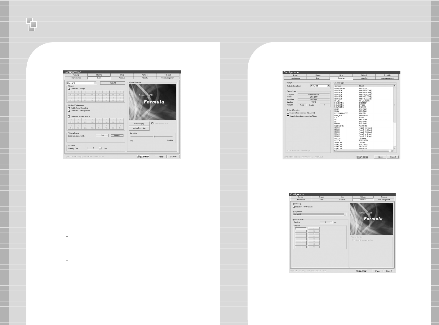
6 Event
※※Sensor Input
- Check [Enable the Sensor] and configure the channel
of camera and sensor input channel.
※※Enable Event Recording
- Use Digital Output OR auto-recording when there is
sensor input signal.
e.g.) Configure 1,2,3,4 Sensor Input for CH1 Camera & 5,6,7,8
Digital Output. Enable Event Recording & Warning Sound from
speaker.
※※Motion Detection
Motion Detection Area Setup, Motion Detection
Sensitivity Setup
Setup MD Area: Setup rectangular area in screen
using the mouse.
Motion Display: Indicate the specific area by
changing color when motion is detected.
Motion Recording: Record when there is movement
in image
7 Receiver
※Port Setup: Select serial port to use PAN/TILT Camera OR Receiver.
※Device Type: Select protocol of receiver from Device Type Panel.
8 Video Out
Video Out function can be used by Loop-Through to analog monitor.
※※Enable the TvOut Rotation :
One channel can be viewed during the directed time gap or
various selected channels can be viewed in timed sequence.
※※Single Mode : Only the selected one channel is viewed
Ⅱ
User Manual - Search Program
34 35
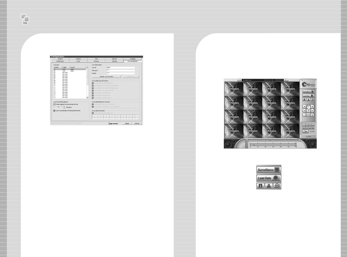
9 User Management
User Managemet can give different authorization levels
for management in accord to user IDs.
※※Insert & Modify User Information
Insert ID & Password and click
[Modify User Information] icon to add new user.
※※Accessible local Functions
Function to manage DVR System in installation
site
–
Support setup for all the functions of DVR.
※※Accessible Network Functions
Setup of only limited function is available for users
connecting from outside using client program
※※Accessible Channels
Direct only certain channels to be viewed according to
user IDs.
1-1 Control Panel
02.Search Program
Search Program allows users to search by time/date & play recorded
images and audio. Support saving of still image by .bmp format,
printing of still image, watermarked .bmp file of each image.
Save Icon →
Print Icon
Serveillance Mode
Icon
Watermark
Viewer Icon
Load Data Icon
- Surveillance Mode Icon: Exit search program and
converts to Survillance Mode(Main Program).
- Load Data Icon: Open Calendar for loading data.
Ⅱ
User Manual - Search Program
36 37
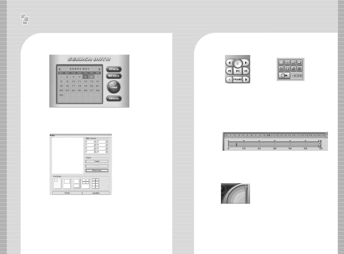
Calendar
MD ONLY Icon: Load Motion Detected data only.
LOAD Icon: Load data of selected date from calendar.
- Save Icon: Save image of selected channels
- Print Icon: Print image of selected channels using printer.
Print Channel: Select channel for printing images.
Option: Print image with caption OR goto printer setup.
Print Type: Setup print layout
Watermark Viewer Icon: Run Watermark Viewer.
Watermark Viewer
Open saved .bmp file to check if there is any image tampering &
check if watermark is identical with original image.
1-2 Playback Control Panel
Supports playback
options: 1x, 4x
playback, reverse
playback, frame by
frame playback.
[Playback Control Panel] [Screen Partition Panel]
1-3 Screen Partition Panel
Support 8 kinds of
various screen partition
display.
1-4 Data Search Process Bar
-
Hour Button: Recorded data of selected hour is indicated in red color.
- Minute Bar: Minute of recorded data is indicated 0~59min. and
recorded data is indicated in red color.
1-5 Search Audio Volume Control Bar
Control audio volume when
replay of recorded data.
Hour Button ←←
Minute Bar ←←