INTO TECH SPLUS DVR BOARD User Manual users manual 2
INTO-TECH Inc. DVR BOARD users manual 2
Contents
- 1. users manual 1
- 2. users manual 2
users manual 2
Ⅱ
User Manual - DVR AVI Backup Manager
40 41
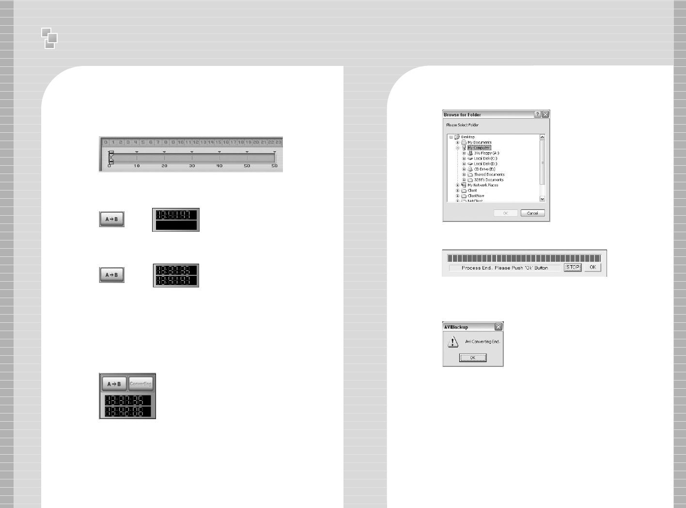
1-4. Backup Time Selection
Enter the time you wish to start backup from Time Bar.
Recorded data is indicated in red.
1-5 Backup Data Converting
Click [Converting] icon after entering the limits of the backup time
in reference.
Click the start time and click [A->B] icon. Start time will
automatically appear as below.
Select the location of the directory to backup data and click [OK].
Click the end time and click [A->B] icon. End time will
automatically appear as below.
※AVI BackUp Manager can only convert files up to one hour. Backup data
time is only indicated when the difference between start time & end time
is less than one hour.
AVI Backup Processing
Windows prompt message indicating AVI Converting End
will automatically appear. You have successfully
converted your data for storage.
Ⅱ
User Manual - Backup Manager
42 43
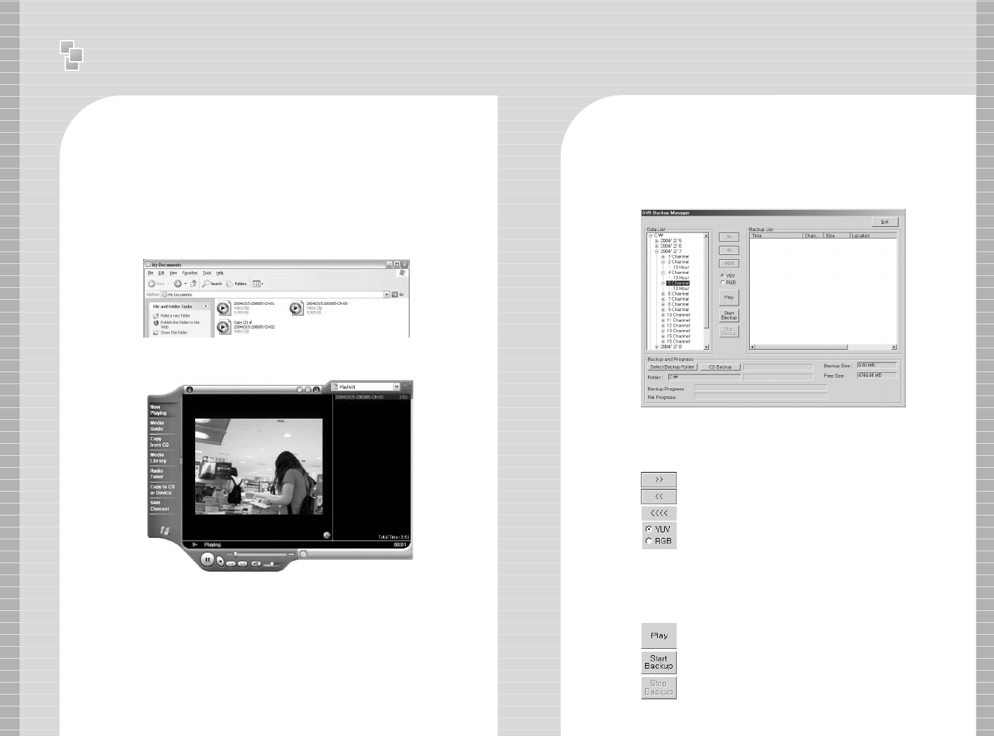
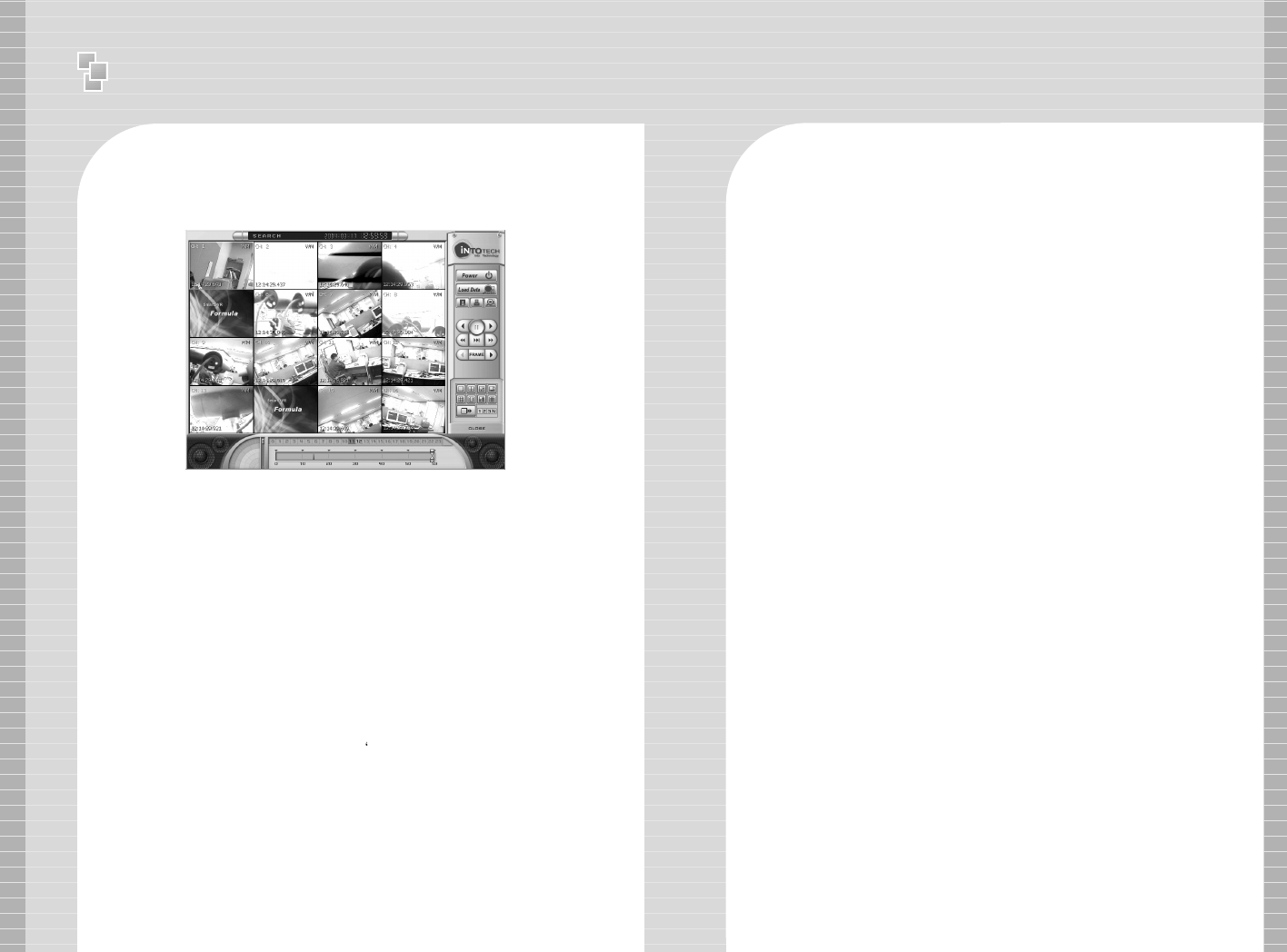
1-6 Play Backup Data using Windows Media-Player
Our website offers utilities that users can Download & install AVI
Formula Codec V 1.0 from www.intotech.co.kr, DownLoad -> Util
section to properly replay stored data.
You can now replay all AVI format data using your Windows
Media Player .
Media Player should replay stored data as seen below.
04.Backup Manager
Using Intotech Backup Manager recorded images(* iva. data) can be
managed efficiently or quickly backup to CD using this software.
[Backup Manager Detailed Information]
: Transfer data to Backup List.
: Remove data from Backup List.
: Remove all data from Backup List.
: Search screen will be displayed in (YUV) screen
mode. (Default setting)
:
Search screen will be displayed in (RGB) screen mode.
Graphic Card may not support YUV mode
YUV is the default setting. (Please convert to RGB
mode when transferring or removing data .)
: Play Backup Data.
: Start Backup.
: Stop Backup.
11 )) Backup Manager illustrates recorded data by date, channel and time.
22))The following icons are used to help manage your recorded data.
Ⅱ
User Manual - Backup Manager
44 45
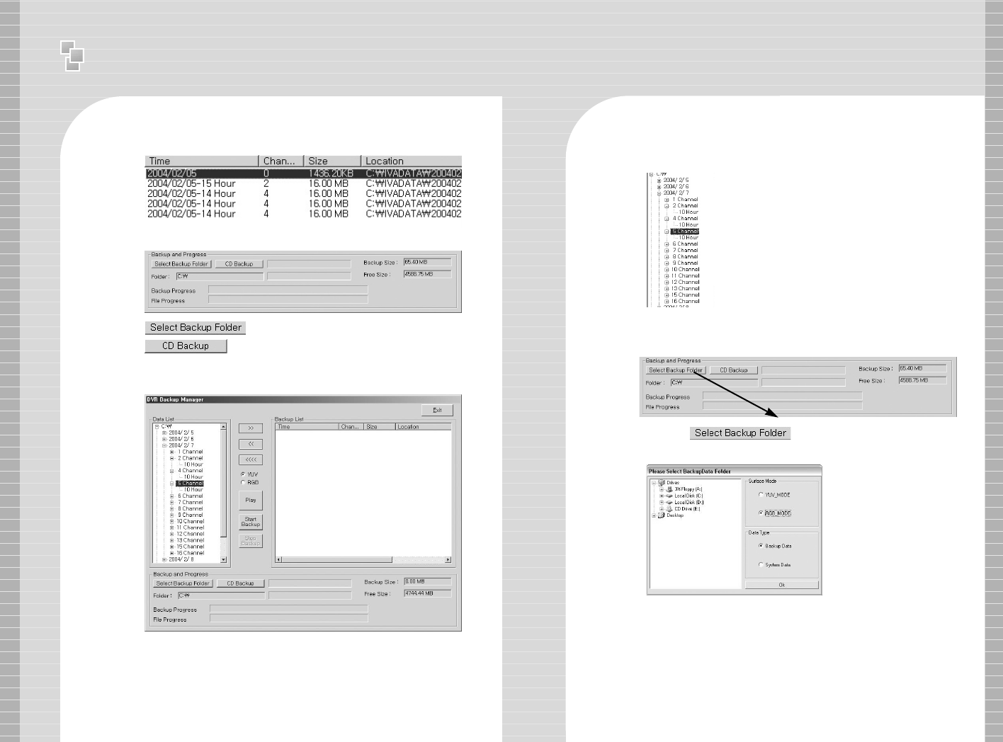
Add data to Backup List illustrated below.
Backup folder & Progress Time Bar is indicated as follows.
: Select directory to backup
: Direct backup to CD (CD-RW required)
1-4 Click() icon to setup backup directory.
1-5 Choose HDD to backup and click [OK].
Example selects C: Drive.
1-1 Backup Manager HDD Backup
1-2 Click Backup Manager icon to run program.
1-2 Select date & time from Data List to Backup.
1-3 Move selected data from Data List to Backup List. Click ( )
icon to move data from Data List to Backup List.
Ex) Indicates 2004/ 2/ 7 CH2 10 o’clock.
Ⅱ
User Manual - Backup Manager
46 47
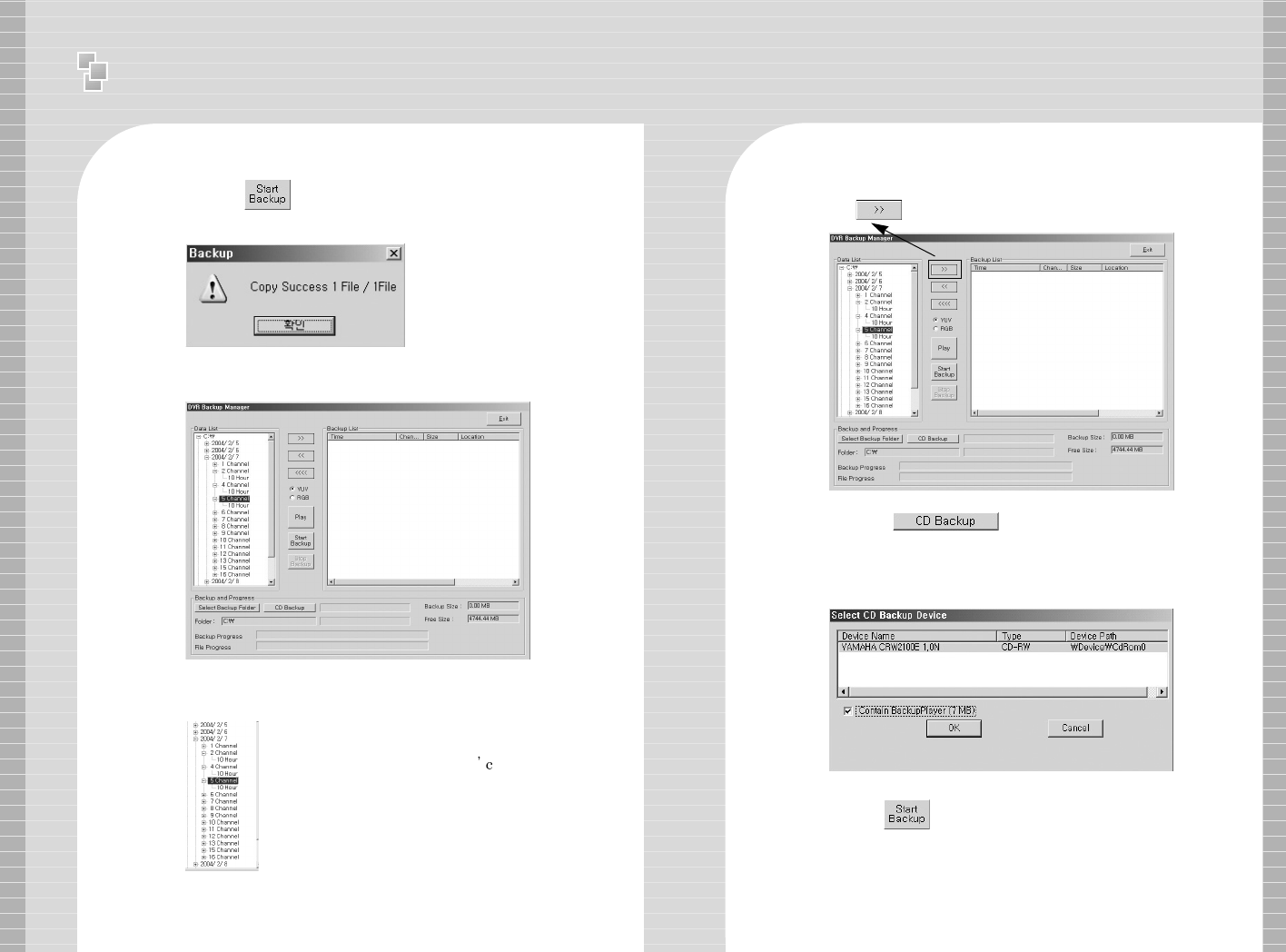
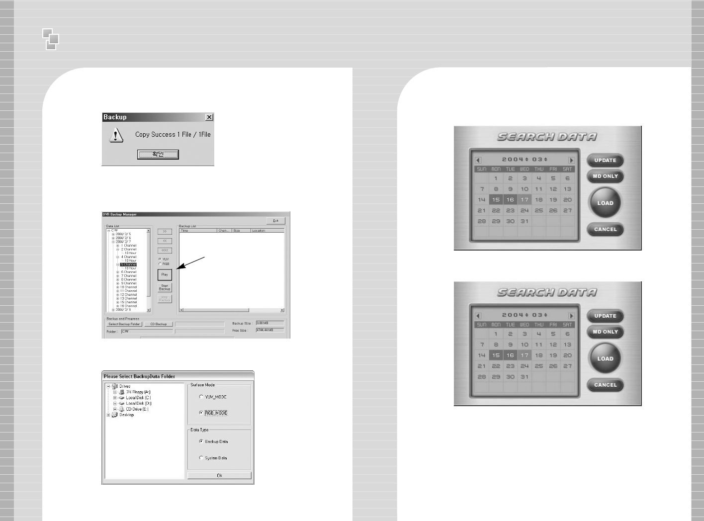
1-6 Click ()icon to start backup..
1-7 Message is displayed after completion.
2 CD Backup
2-1 Click Backup Manager icon and run program.
2-2 Select date & time from Data List to Backup.
2-3 Move selected data from Data List to Backup List.
Click()icon to move data.
Ex) Indicates 2004/ 2/ 7 CH2 10 o lock.
2-3 Click() icon.
2-4 Click [CD – RW] and click [Contain Backup Player].
(NOTE : The Contain Backup Player(7MB) must be checked.)
2-5 Click
()
icon to start backup
Ⅱ
User Manual - Backup Manager
48 49
3 Play HDD Backup Data
3-1 Click Backup Manager and run program.
2-6 Message is displayed after completion. 3-4 Search Data screen illustrated below.
a. Recorded data is shown in red.
3-5 Choose date you want to playback and Click [Load].
3-2 Click [Play] icon to search Backup Data Directory.
3-3 Select RGB Mode and select directory and Click [OK].
aa
⌒⌒
Ⅱ
User Manual - Backup Manager
50 51
3-6 Click icon to exit from playback mode and return to
Backup Manager.
4. Play CD Backup Data
·Insert CD to CDROM. (Run CDROM Drive ->
Backup Player -> Click [ ] icon.)
·Select CDROM directory and click [OK].
[The following Error Messages appear usually means the
following errors.]
[Error Message]
※There is no medium in the burner
: There is no CD inside CD-RW drive.
※If you want to Backup CD. Please reboot or end process
‘imap.exe’
: Please reboot PC OR stop imap.exe’ by force from Windows
Task Manager.
※Set CD recorder failed.
: Conflict with CD-RW settings.
※Not Enough Hdd Disk Free Space to Create CD IMAGE
: HDD must have enough free space to CD backup data onto CD.
※The call failed because IMAPI has not been opened with Open.
: Your Operating System(O/S) does not support CD Backup.
If you have any further tech support issues, please contact your
local Intotech DVR dealer.
Ⅱ
User Manual - NetClient Interface
52 53
4 NetClient Interface
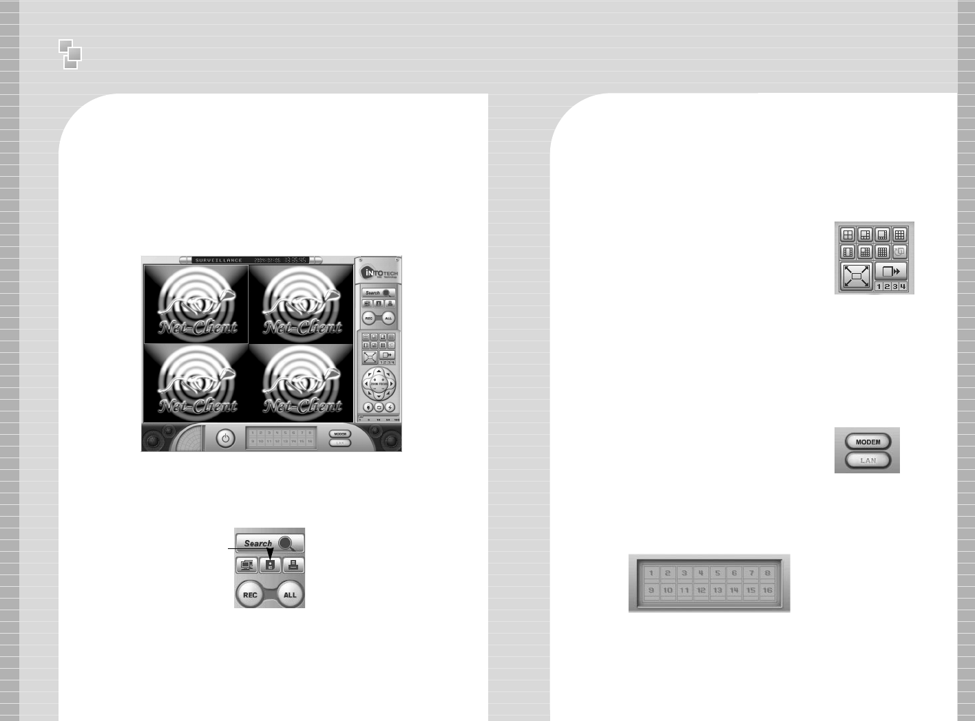
01. Intotech Net-Client Interface
NetClient Program is able to receive images from DVR Server using
the Internet. NetClient functions: Display & recording, camera control
from remote site and other features that we will illustrated in this
document.
1-1 Control Panel
The Control Panel can search program, open connection setup,
save & print still images and record server image from remote PC
where NetClient is installed.
1-2 Screen Partition Panel
Support 7 kinds of various screen partition,
full-screen and sequence rotation display
mode.
Search Icon: Runs search program.
Connection Setup Icon:
Run [Connecting & Configuration Management] used for internet
access. Run [Modem Connection] used for internet access .
1-3 Pan/Tilt Control Panel
Pan / Tilt / Zoom / Focus control is supported from remote site
when DVR Server is using Pan/Tilt camera. Control sensitivity
can be configured in Control Panel.
Only broadband Internet users can use Pan/Tilt control,
Modem users cannot use this feature.
1-4 Network Type Selection Panel
Select [LAN] from Network Type Selection
Panel when using broadband connection
and Select [Modem] when using Modem.
1-5 Camera Selection Panel
Click specific channel from Camera Selection Panel to
enlarge and view image.
→Search Icon
→Print IconConnection Setup Icon →
Save Icon
REC Icon →→All Icon
Save Icon: Save selected channels as JPEG file.
Print Icon: Print the selected channels in various modes.
REC Icon: Record the image of selected channels.
All Icon: Select all channels to record.
Ⅱ
User Manual - NetClient Interface
54 55
1-6 Internet User Real-Time Surveillance
Click [LAN] from [Network Type Selection Panel] and view
real-time from remote site. Click [Connection] from [Control
Panel] and [Connecting & Configuration
Management] screen will appear.
Register the Server IP Address and connect using the
registered IP.
2. Channel Connection
Register the Server and use the registered server to connect
to each channel.
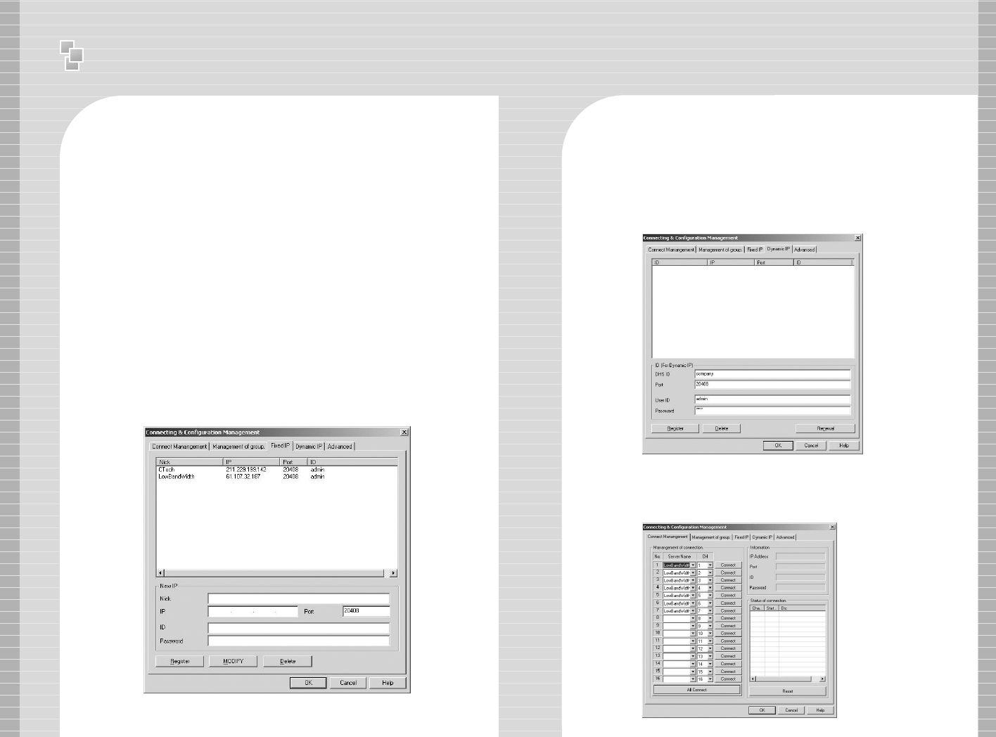
2-1 Server Registration
- Server has Fixed IP(Static IP)
Select the [Fixed IP] from [Connecting & Configuration
Management] insert the Server Name, IP Address, ID &
Password(Insert the ID & Password which is registered in the
Server program [User Management].) and click [Register].
- Server is using Dynamic IP
Register for DHS Service,(http://www.chainip.com )*Refer to
Annex. Select [Dynamic IP] from [Connecting & Configuration
Management] and insert the ID from DHS Server. Insert the ID
& Password which is registered in the Server program [User
Management] and click [Register].
2-2 Connection
Select [Connect Mangement] and insert the Server Name and
Server Channel to each camera channel.
Ⅱ
User Manual - NetClient Interface
56 57
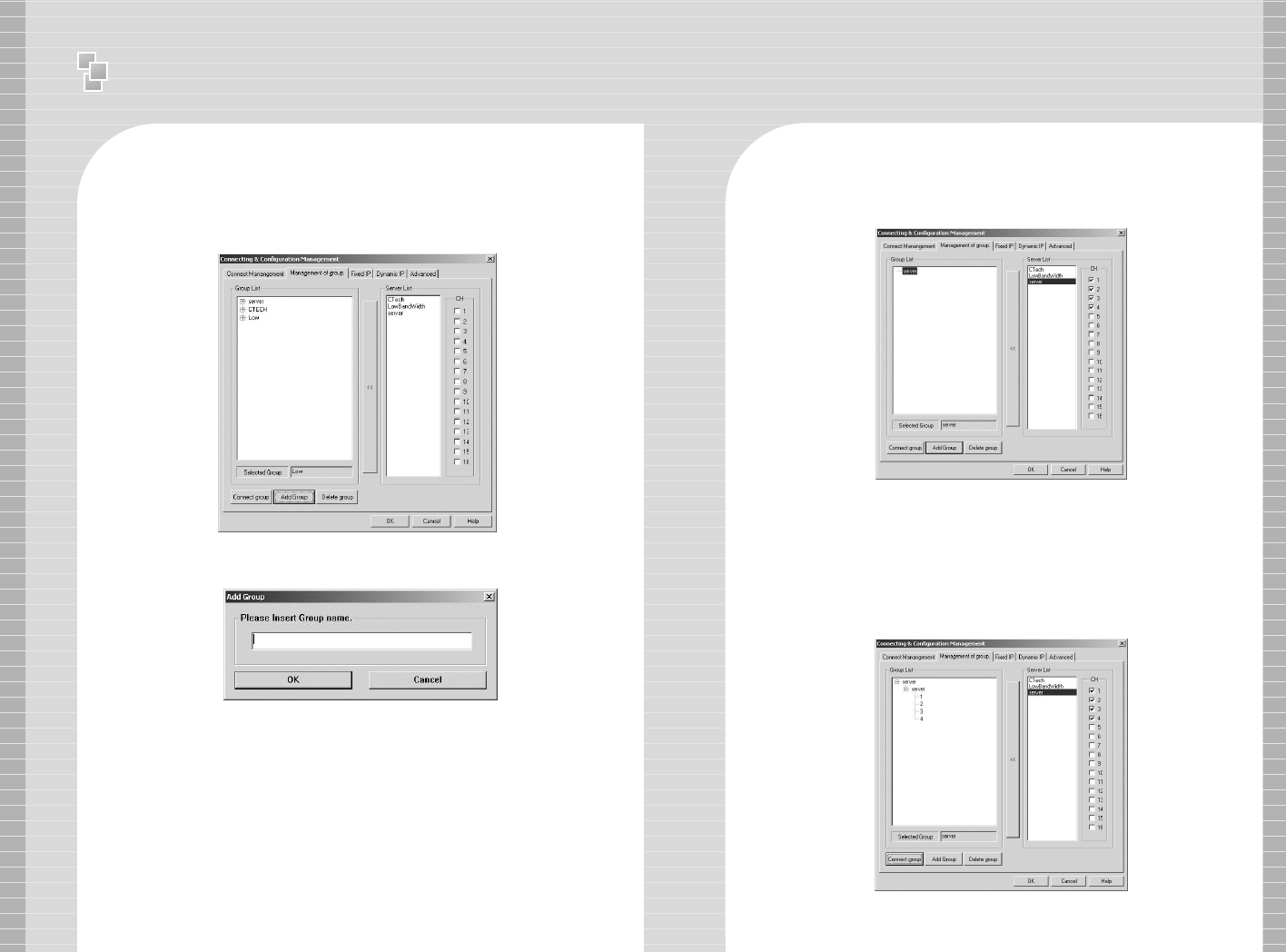
3 Group Connection
Group Connection enable users the convenience of
connecting specific channels from different servers at once.
3-1 Group Setup
- Register Group Name
Goto [Management of group] and click [Add Group]. Insert the
Group Name you wish to use and click [OK].
Group Name will be displayed on left side of Group List.
Select the Group Name from Group List.
3-2 Group Organization.
Click the Server you wish to include in Group from Server List.
Specific channels can be selected after you select Server
Name from Server List.
Select the specific Server channel you wish to include in
Group and click [Add Group].
In one group, users are allowed to register up to 16CH from
different Servers.
Ⅱ
User Manual - NetClient Interface
58 59
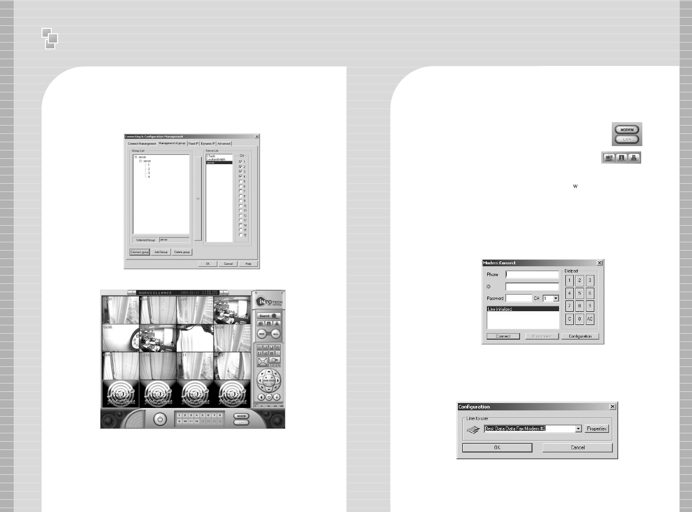
3-3 Group Connection
Click [Connect group] to connect.
(It will take about 10~30 sec to connect to all channels.)
4 Modem User Connection Setup
4-1 Modem Setup
Select [Modem] icon from [Network Type Selection Panel]
to connect from remote site using Modem.
Click [Connection] icon from [Control Panel] to run
[Modem Connect] window.
[Modem Connection] window is initialized. Insert Telephone No.(Insert
the number assigned to DVR Server. Insert “ ” and Telephone No. to
add the waiting time while the line is being dialed. E.g.:
9w0232851525), ID & Password, (Insert the ID & Password which is
registered in the Server program, [User Management].) Select the
camera channel number and click [Connect]. You can only access one
channel at one time using Modem. In order to change to different
channel, click [Disconnect] from [Modem Connect] window, change
channel and reconnect. Note: If You are not using 56K Internet Access,
you do not need to access Internet Service Provider.
Click [Properties] to view General/Advanced default setup.
Use default when use of modem.
4-2 Configuration Setup
The modem model name will appear when you click
[Configuration]. During intial setup, the Model Name needs to
be confirmed to complete registration, thereafter, this step will
be bypassed.
Ⅱ
User Manual - NetClient Interface
60 61
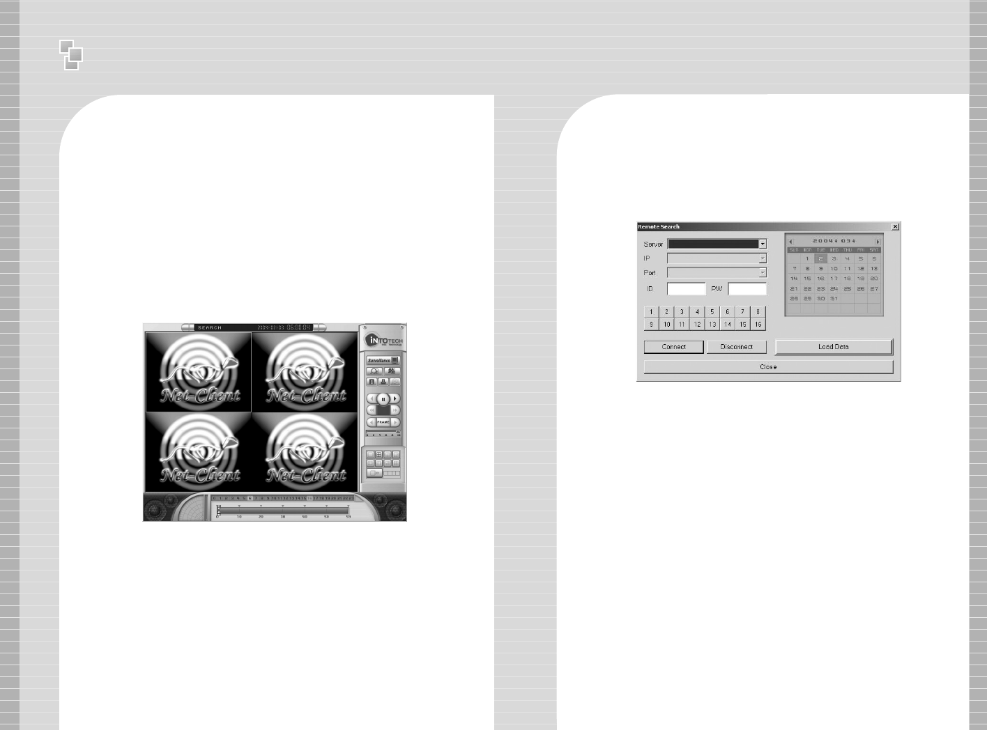
5 Search
5-1 Remote Search
※Broadband: To search recorded images from remote site,
click [LAN] from [Network Type Selection Panel] when using
Broadband Internet connection to connect to Server. Click
[Search] Icon from [Control Panel] to run Search program.
※※Modem: To search recorded images from remote site, click
[Modem] from [Network Type Selection Panel] when using
Modem to connect to Server. Click [Search] Icon from [Control
Panel] to run Search program.
※※Remote Search
[Remote Search using Internet]
- Server Connection: Insert Server, Connection Port, ID &
Password, Channel number and click [Connect].
- Data Load: Click the date from calendar and click [Load Data].
- Insert telephone no. of Server, ID & Password, channel number
and click [Connect].
- Image Output Control Panel: Consists of [Play] & [Stop].
- Screen Partition Panel:
Maximum 4CH search & playback is available from remote site
using Broadband.
1CH search & playback is available from remote site using
Modem.
- Search Data Process Bar
※Hour Bar: If there is recorded data in selected hour, recorded
data is indicated in red from minute bar
※Minute Bar: Minutes of recorded data is indicated from
0~59min. and recorded data is indicated in red.
- Control Panel: Consists of [Surveillance Mode] icon, [Local
Search] icon, [Remote Search] icon, [Save Still Image] icon
and [Print Still Image] icon.
Surveillance Mode Icon: Converts to Surveillance Mode.
Local Search Icon: Runs [Local Search] window.
Remote Search Icon: Runs [Remote Search] window.
Ⅱ
User Manual - WebClient
62 63
5-2 Local Search
Click [Local Search] from Search Mode, Surface Mode
Window will appear. Click [OK] to run Local Search program.
※[Local Search] from NetClient Program is similar to the
functions from Main Program (Server Program). Refer to the
Server Program Manual (Chapter 2: Search Program) for
information regarding other featured functions.
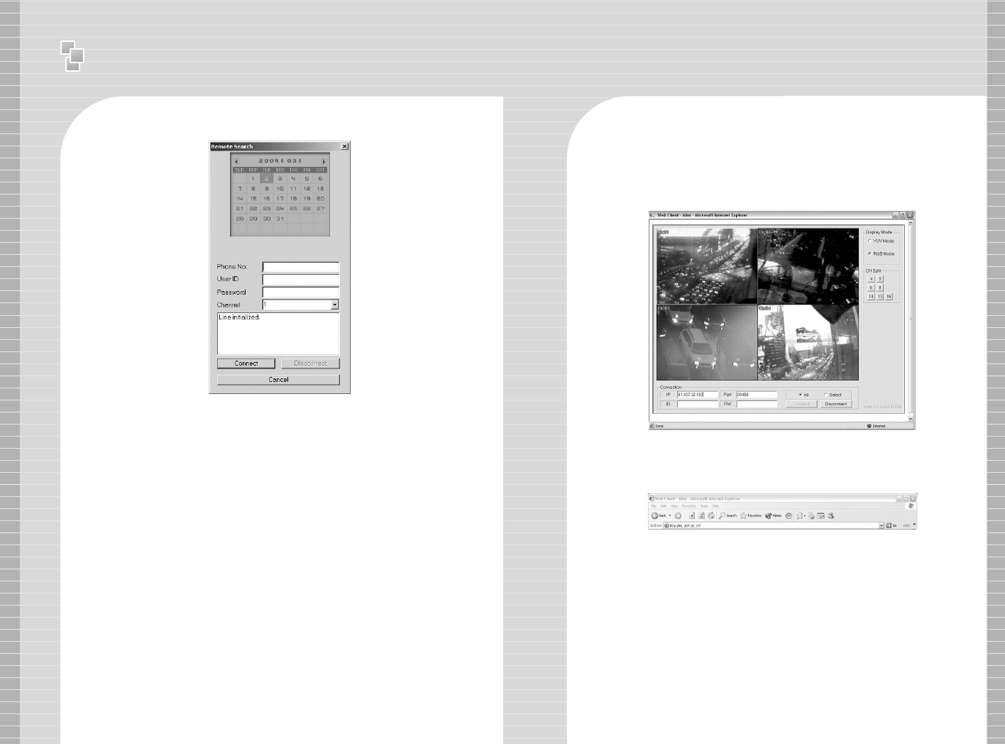
02. WebClient
WebClient can receive the images from remote site & view through
the internet without installing any other program.
1. Connection
1-1 For Fixed IP Users(Static IP)
Insert the Server IP Address in Internet Web Browser.
e.g.: Insert as
http://61.107.32.182:26540 if the Server IP Address is 61.107.32.182.
Ⅱ
User Manual - WebClient
64 65
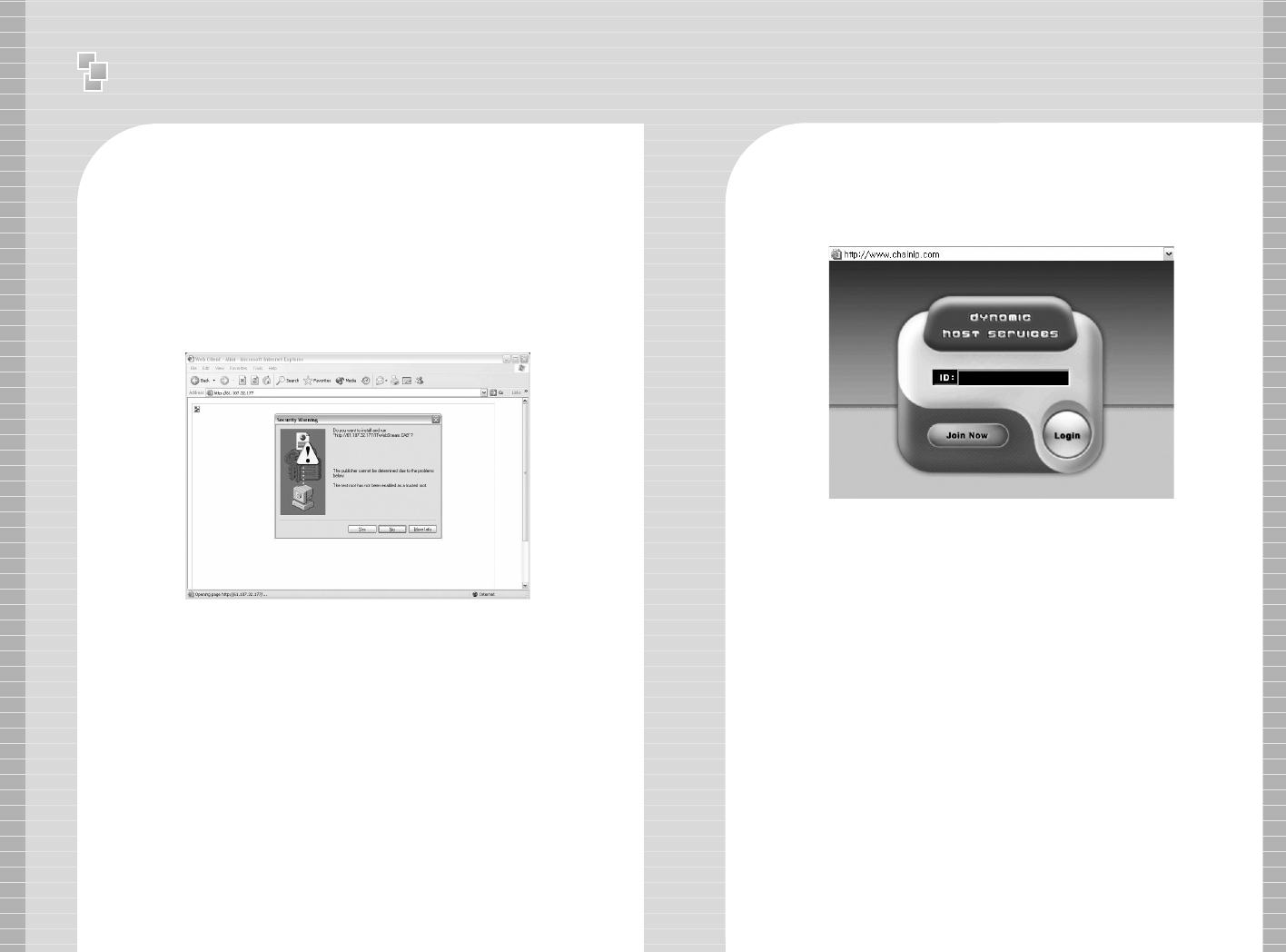
Message as above will appear if this is your first time connecting
through Internet Web Browser.
Click <yes> button and it will take a few seconds to load the
WebClient program.
IP address & Port No. will be automatically retained in the
WebClient program. You will be asked to enter ID & Password
again for security. Click [Connect] to view image.
For Dynamic IP User
Insert the ID you have been given then click [Login] button.
Message as above will appear if it is your first time connecting
through Internet Web Browser.
Click <yes> button and it will take a few seconds to load the
WebClient program.
IP address & Port No. will be automatically retained in the
WebClient program. You will be asked to enter ID & Password
again for security. Click [Connect] to view image.
Ⅱ
User Manual - WebClient
66 67
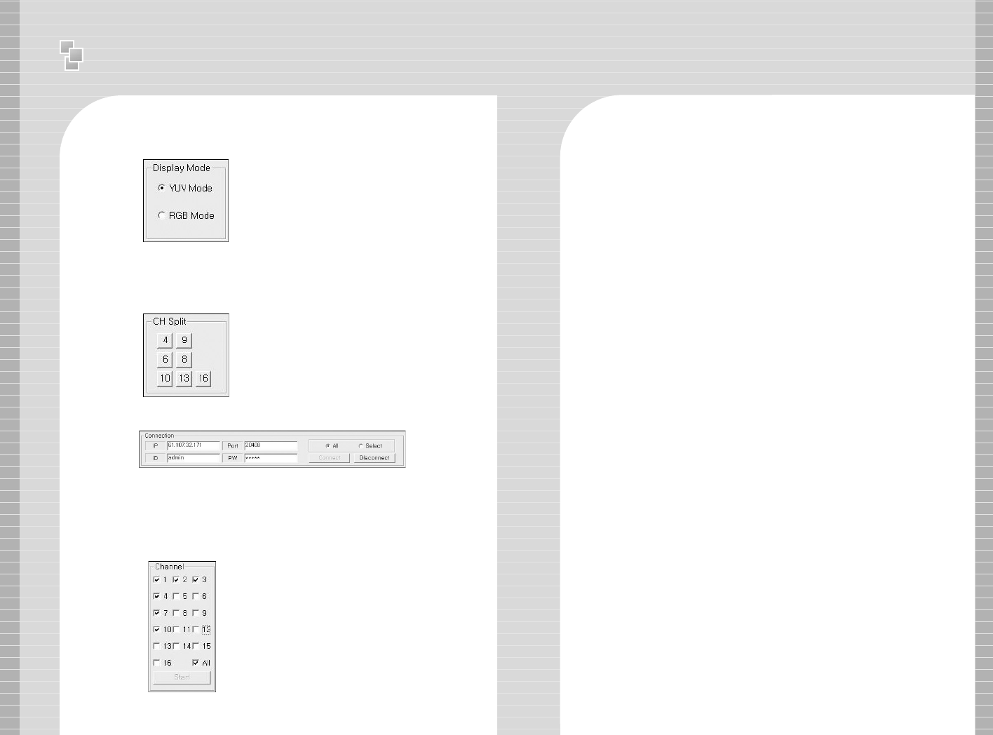
1-2 Display Mode
Display Mode: There are two modes
available: YUV Mode & RGB Mode. RGB
Mode uses more overload than YUV
Mode. If you are not able to view the
images using YUV Mode, update the
Graphics Card Driver and if problem
persists check whether the Graphics Card
supports YUV Mode
Connect to All Channel (All Mode )
WebClient program is set to All Mode as default.
If you wish to view all channels from the Server, click [Connect]
button while it is set to [All Mode].
Connect to specific channel ( Select Mode)
1-3 Screen Partition
There are 7 variations of screen
partitioning that is supported according to
camera number.
If you wish to view specific channels from the
Server(Not all channels), convert to [Select
Mode] and click [Connect] button. Displayed
above, channel selection panel will appear on
the right side of WebClient program. Select
the specific channel and click [Start] button.
1-4 Connection
68 69
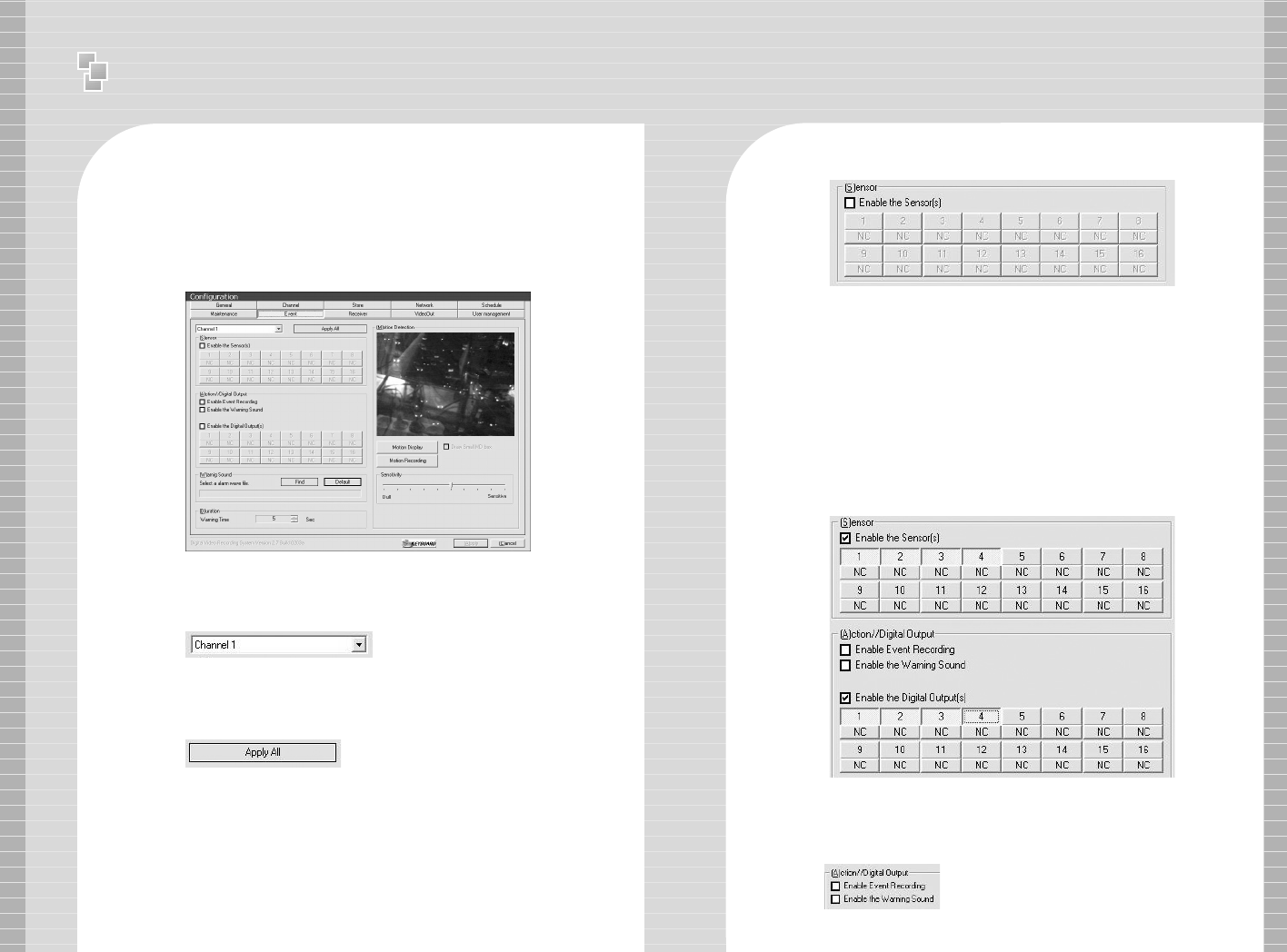
※※I/O DEVICE
9.1 Input/Output Device
Input/Output Control is available from DVR Program [Configuration]
[Event] and it consists of Sensor, (A)ction/Digital Output.
9.2. Channel Selection & Apply All
Select channel after preparation of Input/Output Board and
other Surveillance equipment.
9.3 Sensor Input
[Sensor] is equivalent to Digital Input. When there is input signal
from outside to selected channel(Sensor is activated, e.g.: When
use of fire alarm, sensor is activated when occurrence of fire),
selected channel will recognize as occurrence of event.
All the surveillance equipment is connected to every channel, and
to control all channel, click [Apply All] after setup of [Sensor],
[Action/Digital Output], [Digital Output], [Warning Sound],
[Duration].
9.3.1 NC
[NC] stands for “Normal Close”If this button is selected,
Normally(Event is not occurred) the circuit will be closed. General
Sensors are “Normal Close”but in case of special sensor which is
“Normal Close”type, do not select [NC].
9.3.2 Sensor Port Control
Confirm the video channel of sensor you want to insert, then
click [Enable the Sensor]. Setup the sensor port which is
connected to SmartDVR I/O Board by each channel. Can use
sensor port regardless of digital output number.
9.4 Action//Digital Output
Action//Digital Output - [Enable Event Recording] will automatically record
the image when sensor is activated after an occurrence of event. [Enable
the warning sound] will make a warning sound from the speaker.
※
Annex 1. I/O DEVICE
※
Annex 2. Dynamic IP User Manual
70 71
※※Dynamic IP User Manual
1-1 DHS(Dynamic Host Service)
DHS service helps support Dynamic IP remote access. Internet
Service Provider frequently change IP address when using a
standard broadband connection. DHS Hosting Service keeps
track of Server ID and updates IP address periodically to support
remote access without the need of a Static IP Address.
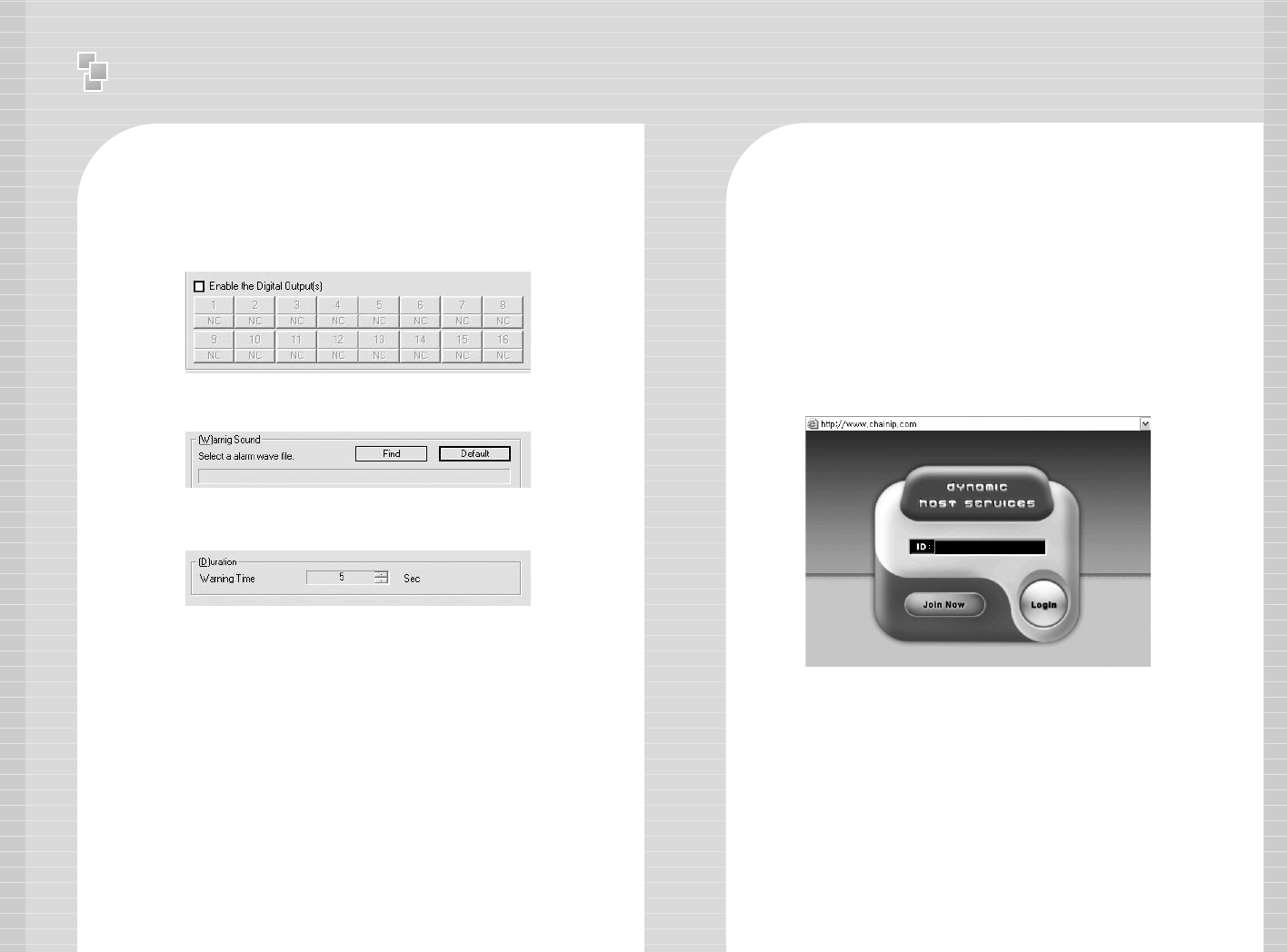
1-2 DHS Service Registration
- Connect to http://chainip.com from Internet Web Browser.
2 Click [Join Now] and enter information on registration form.
3 Our server manager will contact you within 24 hours after the
registration is complete.
4 Connect to http://chainip.com and login with the ID that has been
assigned to you.
9.5 Digital Output
Confirm the video channel of digital output you want to insert,
then setup [Digital Output]. Setup the Digital Output Number
by each channel. Can use digital output port regardless of
sensor input number.
9.6 Warning Sound
Select Wave file to change warning sound.
9.7 Duration Time
Setup duration time of Warning Sound using mouse wheel.
※
Annex 3. IP Router
72
※※IP Router User Manual
For Customers who use Routers inside their intranet environment
for PC & DVR internet access.
1 The following steps will guide you to allocate Private IP address
to DVR Server.
Goto [Start] – [Control Panel] – [My Network Places]
2 Click the right mouse button from [Local Area Connection] in
LAN or High Speed Internet.
3 Click [Properties].
4 Double click [Internet Protocol (TCP/IP)].
5 Manually input private IP address, do not select [Automatically
Obtain IP Address.] If you do not know your IP address:
Click [Start] – Click [Run] and enter cmd or command and press
OK. A black DOS screen will appear, then type ipconfig’ and
press Enter. Your IP Address, Submask and GateWay will be
displayed, use these IP addresses and enter into Step 5
- Insert ‘168.126.63.1’ for DNS.
6 After the setup is complete, you must access your router to set
Port Forwarding.
- Refer to Router manual since Port forwarding function is
different for every Router.
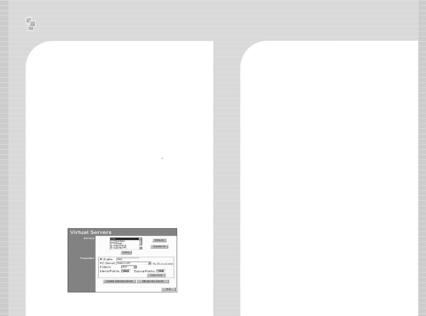
<Following is an example of AnyGate IP Router.>
Port forwarding Port No. : 20408, 26540
7 Refer to Dynamic IP Manual after the above setup is complete.

FCC NOTICE
THIS DEVICE COMPLIES WITH PART 15 OF THE FCC FULES.
OPERATION IS SUBJECT TO THE FOLLOWING TWO CONDITION:
(1) THIS DEVICE MAY NOT CAUSE HARMFUL INTERFERENCE, AND
(2) THIS DEVICE MUST ACCEPT ANY INTERFERENCE RECEIVED,
INCLUDING INTERFERENCE THAT MAY CAUSE UNDERSIRED
OPERATION.
This equipment has been tested and found to comply with the limits for a Class B digital device, pursuant to part 15 of the FCC Rules.
These limits are designed to provide reasonable protection against harmful interference in a residential installation. This equipment generates, uses
and can radiate radio frequency energy and, if not installed and used in accordance with the instructions, may cause harmful interference to radio
communication. However, there is no guarantee that interference will not occur in a particular installation. If this equipment does cause harmful
interference to radio or television reception, which can be determined by turning the equipment off and on, the user is encouraged to try to correct
the interference by one or more of the following measures :
- Reorient or relocate the receiving antenna.
- Increase the separation between the equipment and receiver.
- Connect the equipment into an outlet on a circuit difference from that to which
the receiver is connected.
- Consult the dealer of an experienced radio/TV technician for help.
NOTE : The manufacturer is not responsible for any radio or TV interference caused by unauthorized modifications to this equipment.
Such modifications could void the user’s authority to operate the equipment.
