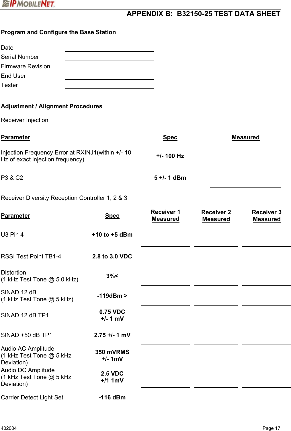
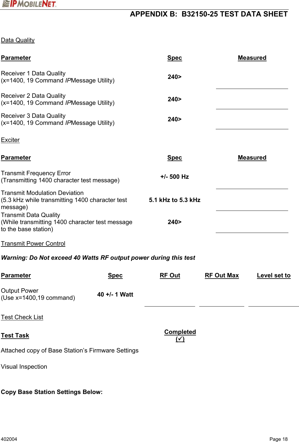
IP Mobilenet B32150-25 Base Station Data Radio User Manual 402004

IP Mobilenet, LLC Base Station Data Radio 402004

Users Manual

          IIPPSSeerriieess    BB3322115500--2255  BBaassee  SSttaattiioonn  PPrroodduucctt  OOwwnneerr’’ss  MMaannuuaall       Date Released:  December 4, 2003  Document #:  516.80517.POM Version: X1           Copyright 2003 IPMobileNet, Inc.  .  16842 Von Karman Avenue, Suite 200   Irvine, CA  92606 Voice: (949) 417-4590       Fax: (949) 417-4591
402004   Page ii                         The term “IC”: before the radio certification number only signifies that Industry of Canada technical specifications were met.  Operation is subject to the following two (2) conditions: (1) this devise may not cause interference, and (2) this device must accept any interference, including interference that may cause undesired operation of this device.        The following U.S. Patents apply to this product:    U.S. Patent numbers 5,640,695,6,018,647,6,243,393  Information contained in this document is subject to change without notice.  All rights reserved.  Reproductions, adaptations, or translation without prior written permission is prohibited, except as allowed under copyright laws.
 TABLE OF CONTENTS   402004   Page 3  SECTION 1:  THEORY OF OPERATION .................................................................................................... 4   General Block Diagram.................................................................................................................. 4     General Block Diagram Definitions..................................................................................... 4    Input/Output ........................................................................................................... 4    System Controller................................................................................................... 4     Modems........................................................................................................... 5     Diversity Reception.......................................................................................... 5    RX Injection............................................................................................................ 5    Transmitter ............................................................................................................. 5    Receiver 1/ 2/ 3...................................................................................................... 5    Power Supply......................................................................................................... 5  B32150-25 Base Station Section Descriptions ........................................................................... 6   System Controller................................................................................................................ 6   Input/Output ........................................................................................................................ 6   Modem Switching................................................................................................................ 6   Modem ...............................................................................................................................7     Receive Signal Strength Indication Comparator................................................................. 7   Baseband ............................................................................................................................ 8   Receiver Board ................................................................................................................... 8   IF Amplifier .......................................................................................................................... 8   Receiver Injection................................................................................................................ 9   Exciter Board....................................................................................................................... 9   Analog Modulation ............................................................................................................ 10   Phase Locked Loop .......................................................................................................... 10   Power Amplifier................................................................................................................. 11   SECTION 2:  FCC LABEL.......................................................................................................................... 12  B32150-25 Base Station FCC Label Placement ........................................................................ 12  B32150-25 Base Station FCC Label............................................................................................ 12   APPENDIX A: B32150-25 CIRCUIT BOARD DIAGRAM.......................................................................... 13  APPENDIX B: B32150-25 TEST DATA SHEET........................................................................................ 17
 SECTION 1:  THEORY OF OPERATION   402004   Page 4   GENERAL BLOCK DIAGRAM       General Block Diagram Definitions     For increased data security, the modem supports the U.S. Government developed Digital Encryption Standard (DES) data encryption and decryption protocols.  This capability requires installation of third-party IP compliant DES encryption and decryption software.    The standard IPSeries base station circuit board contains five (5) main sections defined below:   Input/Output    Circuitry associated with one of the following base station’s data connectors:   RS232 Serial Port DB9 Data Connector   RJ45 Ethernet 10 Base T Interface Connection  System Controller    Houses the modem, diversity, and Ethernet circuitry.  Manages the operation of the base station’s modem providing transmit timeout protection in the event a fault causes the base station to become halted in the transmit mode.  The system controller also handles the loading of selected transmit and receive frequencies into the injection synthesizer.  Includes memory for storage through Electrically Erasable Programmable Read Only Memory (EEPROM) of the base station’s operating parameters, which are retained after the base stations power is cycled off.
 SECTION 1:  THEORY OF OPERATION   402004   Page 5  Modems Convert data into an analog audio waveform for transmission and analog audio from the receiver to serial data interface.  There is one (1) modem that is dedicated to the transmit operation and two (2) modems dedicated to the receive operation.  The modem dedicated to the transmit supports a 115.2 KBPS data transmission rate on the serial port, SLIP protocol, and a 32 KBPS over-the-air data transmission rate.  Provides Forward Error Correction (FEC) and Error Detection (CRC), bit interleaving for more robust data communications, and third generation collision detection and correction capabilities.   Diversity Reception Circuitry selects one of three (3) diversity receiver audio outputs for processing by the modem by comparing the Received Signal Strength Indication (RSSI) output from each receiver.  Audio from the receiver with the highest RSSI value is passed to the modems.  RX Injection  The Injection Synthesizer board provides a highly stable local oscillator signal for the three (3) receivers.  This displays a serial data input/output interface, synthesizer, and VCO.  Transmitter    Consists of an exciter and a power amplifier module covering various frequency bands in segments.  A different power amplifier module is required for each segment.  The transmitter power control is included with the power supply circuitry on the same board.  Receiver 1/Receiver 2/  Uses three (3) discrete receivers tuned to the same frequency.   Receiver 3  The three (3) receivers are required to support IPMobileNet’s base station Diversity Reception System (DRS).   NOTE:  Some installations use only two (2) receivers.    The receivers are double-conversion superhetrodynes with an Intermediate Frequency (IF) of 45 MHz.  Each receiver consist of bandpass filters, RF amplifiers, a mixer, 45 MHz crystal filter, and a one-chip IF system.  The injection synthesizer provides the first local oscillator signal and outputs from each receiver including RSSI and analog audio for Diversity Reception.  Power Supply    Power supply circuitry derives the various operating voltages required by the base station.  Fixed voltage regulators are employed through the base station for this purpose.
 SECTION 1:  THEORY OF OPERATION   402004   Page 6 B32150-25 Base Station Section Descriptions  System Controller    This section displays the Central Processing Unit (CPU)(U1), clock, and power-on reset circuitry.  It provides more processing power than required for future capabilities to be incorporated without changing processors.  Such capabilities include data encryption/decryption (DES) and remote fault monitoring.  U1 features a 16-bit address bus and 128K of internal flash random access memory (RAM).    NOTE:  To enter the programming mode it is necessary to reset the switch (S1) and power up again.  CPU operations are controlled by Y3 an 18.432 MHz clock module.    Capacitor (C1) and an internal Schmidt trigger circuit inside of U1 generates the power on reset signal.  The RESET* output from U1 drives a latch and decoder found elsewhere on the board.  This section displays the RAM, decoder, EEPROM, and programming power supply circuitry.  U2 is a 512K x 8 bit static RAM chip, which provides temporary storage of base station configuration data while the power is on.  This is necessary in order to program the base station.  U2 is controlled directly by the address, data, and control busses from the CPU.  Chip U5 decodes the A11-A14 address bus to provide chip selects for the modem and EEPROM memory.  Chip U6 is an 8-bit latch.  It latches inputs from the D0-D7 bus and lights the front panel status indicators (TX, CD, RX1, RX2, and RX3).  Chip U3 is a serial EEPROM, which provides 2K bits of pre-programmed data storage for the CPU.  Data is clocked out of U3 by EECLK, and back into the CPU via EEDATA.  A programming power supply is required for the flash RAM inside of the CPU, and this function is performed by U4.  This chip is a low dropout voltage regulator with a shutdown control.  Resistors R22 and R21 set the output voltage.  When the base station configuration data is to be stored in flash RAM, the CPU makes VPP_ENABLE high.  This turns on the regulator, producing a 12-volt output via VPP for the flash RAM.  This section displays a dedicated processor and voltage regulator.  Chip U7 is a processor, which permits manual keyboard operation of the base station.  Regulator VR2 provides 5 volts DC power for all logic circuitry on the System Controller Board.  Input/Output   This section displays the CPU input/output circuitry.  Chip U8 is an RS232 transceiver, which interfaces the CPU to the modem via J1.  From there, the RS232 data goes directly to a rear panel DB9 connector.  U8 converts 5-volt logic-level data to +/-12 volt data in RS232C form, and vice-versa.  A charge pump power supply on the chip converts the +5 volt DC power to the +/-12 volt levels required.  The charge pump uses capacitors (C28 to C31) to generate voltages.  NOTE:  The RS232 serial port data transmission rate of the base station is 115.2 KBPS.   Modem Switching  This section displays the connector wiring and modem switching circuitry.  Connector J7 is routed to the front-panel TX, CD, and RX1-RX3 LED indicators.  The base station will also accept modulation from an external source (modem or amplified microphone audio).  Transmission gate U10A switches this signal source.
 SECTION 1:  THEORY OF OPERATION   402004   Page 7 Modem    This base station uses separate modems for receive and transmit functions so that full-duplex operation may be obtained.  The A0-A1 address bus in addition to the individual read (RD*), write (WR*), and chip select (MODEMTXCS*) lines control all three (3) modems.  Modem operations are timed by Y2, an 8.0 MHz clock module.  Modem chip U14 is dedicated to the transmit operation.  Data from the D0-D7 bus is read by the chip, and then converted to a 4-level FSK analog signal, which appears on the TXOUT pin.  Op amp U21B buffers the signal, which becomes the MODEM_TXMOD output.  From this point, the signal is routed to the modulation circuitry on the Exciter Board.  Chip U14 has the ability to demodulate receiver audio, although this capability is not used in most systems.  Incoming data-bearing audio from the Diversity Reception circuitry (and selected receiver) appears at DISC_AUDIO.  The signal passes through resistor R54 and into the modem chip.  Resistor R52 and capacitor C41 serve as feedback elements, limiting both the gain and bandwidth of an amplifier within U14.  The modem chip demodulates the audio into 8-bits of data, which exit U14 on the D0-D7 bus.  Chip U14 also provides a bias voltage for the analog circuitry on the Exciter Board.  This voltage is about 2.5 volts DC, and it appears on the VBIAS line.  The purpose of VBIAS is to bias the Exciter Board analog circuitry for proper operation.  Please note that if this voltage is low or missing, the Exciter Board circuitry may not work.  Modem chip U15 is dedicated to the receive operation.  Incoming data-bearing audio from the Diversity Reception circuitry (and selected receiver) appears at DISC_ AUDIO.  The signal passes through resistor R56 and into the modem chip.  Resistor R55 and capacitor C46 serve as feedback elements, limiting both the gain and bandwidth of an amplifier within U15.  The modem chip breaks down the audio into 8 bits of data, which exit U15 on the D0-D7 bus.  Modem chip U16 is also dedicated to the receive operation, although it may not be used in this application.  The operation of U16 is exactly the same as U15.  Receive Signal Strength Indication Comparator   This section displays the RSSI comparator circuitry.  A series of comparators (U20BCD) simultaneous compare RSSI1 to RSSI2, RSSI2 to RSSI3, and RSSI1 to RSSI3.  Within this process eight (8) possible results are then forwarded by the comparators to a series of NAND gates (U18ABC), which reduce the number of results to three (3) and translates the results for an analog multiplexer (U19A).  To determine which of the three (3) results is the strongest, the following needs to occur:     For Receiver 1 to be selected as the strongest signal, both input pins on the NAND gate (U18D) must go high (driving pin 7 of U19A).  If Receiver 1 has the strongest signal, a light emitting diode (LED)(D1) lights indicating Receiver 1 was selected.   For Receiver 2 to be selected as the strongest signal, the inverter (U17B) must go high (driving pin 6 of U19A).  If Receiver 2 has the strongest signal, D2 lights indicating Receiver 2 was selected.   For Receiver 3 to be selected the strongest signal, the inverter (U17C) must go high (driving pin 5 of U19A).  If Receiver 3 has the strongest signal, D3 lights indicating Receiver 3 was selected.  SEL_RSSI is the output selected with the strongest signal.  When RSSI voltage exceeds a threshold, another LED (D4) lights.  As the other three (3) LEDs, this circuit is intended as a diagnostic tool.  It provides a go/no go indication that an RF signal has been received.  A pot (R74) sets the turn-on voltage.
 SECTION 1:  THEORY OF OPERATION   402004   Page 8     Baseband   This circuitry amplifies the audio from each receiver, routes it through a RF multiplexer, and selects the audio from the receiver with the highest RSSI value.  The comparator circuit on the previous sheet controls it.  There are three (3) channels of audio, with separate gain and DC offset adjustments to compensate for performance differences in the receivers.  For example, incoming audio from receiver 1 appears at AUDIO 1.  An op amp (U12D) is then amplifies the audio.  A pot (R72) adjusts the gain, while another pot (R57) adjusts the DC offset on the output.  The amplifier output passes through a RF multiplexer (U19B), then drives a low pass filter (U9) through another op amp (U12A) and through the AUDIO_OUT line, which goes to a switch (S3) and to pin 4 of a connector (J3).  The remaining audio circuits work in the same manner.  The output from U19B also appears on DISC_AUDIO, which goes to the CPU (U1) and from there the audio is demodulated by the modems.     Receiver Board        Please be aware that the base station uses three (3) identical receiver boards.  As a result, the circuitry will be described only once.    Front end.  Incoming signals pass through a SAW filter (FLT1).  The desired signals are amplified by U2 and additional selectivity is provided by a monolithic SAW filter (FLT2).  Another amplifier (U1) further amplifies the signal and the output pass through two (2) crystal filters (FLT4 and FLT5).   IF Amplifier   The incoming 45 MHz signal goes to U3 a super heterodyne IF subsystem.  Inside the chip, the signal is applied to a mixer.  The mixer also accepts a 44.545 MHz local oscillator input.  The local oscillator consists of an internal amplifier, plus crystal (Y1) and associated components.  The mixer output passes through FLT6, a 455 KHz ceramic IF filter.  It is amplified, passed through ceramic filter (FLT7), and on to a second IF stage.  The IF output drives a quadrature detector.  The recovered audio appears at pin 9, while RSSI appears at pin 7.  Within the RSSI circuitry, chip U3 uses a detector, which converts the AGC voltage generated inside the chip into a DC level corresponding logarithmically to signal strength.  RSSI is used by Diversity Reception on the System Controller to select the receiver with the highest quality signal.  A filter consisting of a resistor (R14) and a capacitor (C32) provides high frequency de-emphasis for the audio.  The audio is buffered by op amp U4A.  From there the AUDIO output line goes to a connector, for hookup to Diversity Reception on the System Controller Board.  Resistor (R15) and capacitor (C33) provides RF filtering for the DC RSSI voltage.  The RSSI is buffered by op amp U4B.  From there the RSSI output line goes to a connector, for hookup to Diversity Reception on the System Controller Board.      Several sets of 455 KHz IF filters (FLT6 and FLT7) are available to suit receiver selectivity requirements.  Should replacement of these filters be required, exact replacement parts must be used.
 SECTION 1:  THEORY OF OPERATION   402004   Page 9 Receiver Injection   This displays a serial data input/output interface, synthesizer, and VCO.  The I/O interface circuitry accepts clock, serial data, and enable signals from the System Controller Board via terminal block TB1.  A lock detect (LD) status output is returned to the System Controller Board from the synthesizer.  U1 is a hex Schmidt Trigger inverter, which squares up incoming signals for reliable operation of the synthesizer chip.  This is necessary because of a cable run between the two (2) boards.  The main section of this board is synthesizer chip (U2).  The device contains the key components of a phase locked loop (PLL), including a 1.1 GHz prescaler, programmable divider, and phase detector.  In operation, the desired frequency is loaded into U2 as a clocked serial bit stream via the CLK and DATA/I inputs.  The lock detection circuitry consists of inverters U1E/U1F, diode CR1, and resistor R4.  When the synthesizer is in lock, the LD pin on U2 is high, making the LD output on terminal block TB1 high.  The EXC LD input on TB1 routes the lock detect output from the Exciter Board through diode CR1, and out through LD.  This configuration tells the CPU on the System Controller Board that it is acceptable to process received data, or to key the transmitter when LD is high.  Otherwise, if a fault in either synthesizer prevents a lock, receive and transmit operation will be inhibited.  Other items of interest include a programming switch and serial data output.  Switch (JMP1) may be used to program the firmware configuration inside chip U2.  The system controller board performs programming so a jumper is installed in the LNVCC (operation) position instead.  The EXT DATA output on block TB1 sends frequency programming data to the transmitter synthesizer on the Exciter Board.  The injection signal is generated by module U7.  This device is an RF oscillator with buffered outputs.  The voltage is generated by the phase detector output (PD/O) of U2, which drives a loop filter consisting of R5, C8, C5, R3 and C9.  The filter integrates the pulses, which normally appear on PD/O into a smooth DC control signal for the oscillator.  This section displays the DC power supplies, frequency reference, and RF output circuitry.  Regulator VR1 provides 9 volts DC for U7, and RF amplifier (U6).  Regulator (VR2) provides a low noise 5-volt DC output for inverter (U1), synthesizer (U2), and reference (Y1).  Reference module (Y1) provides a high-stability 10 MHz reference frequency.  Y1 is a voltage controlled, temperature controlled crystal oscillator (VCTCXO).  This device also has a VC input which accepts a control voltage from pot R10.  The pot permits a slight shift in the reference frequency which enables the three (3) receivers to be tuned precisely to the assigned receive frequency.  A diode (CR2) provides additional voltage regulation, improving the frequency stability of reference Y1.  The RF output circuitry consists of RF amplifier (U6), and power splitters (U5, U3, and U4).  U6 increases the signal level to correct for losses in the splitters.  The splitter U8 provides two (2) RF outputs.  One output drives splitter U5, which provides local oscillator injection for receivers 2 and 3.  The other output drives splitter (U4), which drives receiver 1 and the PLL_FEEDBACK input on chip U2.   Exciter Board   This section displays the input/output interface, transmitter keying, and power supply circuitry.  The input/output interface is built around terminal block (TB1) and Schmidt Trigger inverters (U2).  Incoming clock, serial data, and chip select signals on block TB1 are squared up by U2.  Then they are sent to the appropriate inputs on the transmitter synthesizer (U9).  The EXCDATA source comes from the receive synthesizer on the Injection Synthesizer Board.  A Schmidt Trigger chip is used here because of a cable ran to the System Controller Board.  The synthesizer returns a lock detect output to the Injection Synthesizer Board via U1 and EXCLD.
 SECTION 1:  THEORY OF OPERATION   402004  Page 10 A regulator (VR2) powers the T/R switch circuitry.  When the System Controller Board makes TXKEY* low, inverter U1B goes high, turning on transistor Q2 and FET Q1.  This applies 5-volt power to the TXENABLE output, turning on the T/R switch on the Power Amplifier Board.  At the same time, transistor Q3 conducts, grounding the KEY* input of the Power Amplifier Board.  Finally, inverter U1A goes high and turns on RF switch U7, connecting the VCO output to the Power Amplifier Board for transmission.  The power supply consists of two (2) voltage regulators.  A regulator (VR1) provides 9-volt power for the VCO.  Another regulator (U3) provides low noise 5-volt power for the logic circuitry, synthesizer chip, and analog circuitry.   Analog Modulation   This section displays the analog modulation circuitry.  Incoming modem audio from the System Controller Board appears at TXMOD, and is buffered by op amp U4A.  If an external modulation source (modem or amplified microphone) is connected to the base station’s DB9 connector, audio appears at EXTMOD.  From there the audio passes through low pass filter U6.  The audio is inverted and amplified by an op amp (U4B).  It then passes on to the VCO module via VCOMOD.  Pot R18 adjusts the level to suit the VCO.  The 10 MHz reference is also modulated in order to counteract the corrective effects of the synthesizer loop circuitry.  For example, if only the VCO were modulated, the synthesizer would try to compensate for the frequency “error,” caused by the modulation.  This effectively reduces the amount of modulation available.  Modulating the reference and the VCO simultaneously deceives the loop into not compensating for the modulation, because when the reference frequency goes high, the VCO frequency goes high, and vice-versa.  An op amp (U5B) amplifies the AUDIO output from another op amp (U4B) and applies it to jumper block JMP1.  Pot R12 adjusts the gain of U5B.  Op amp (U5A) inverts the phase of the audio and applies it to the other side of jumper block JMP1.  The purpose of the jumper block is to select the proper phase of the audio.  If the wrong phase is used, on modulation peaks the reference will swing in the same direction as the VCO, canceling out most of the modulation.  The output from the jumper block goes to the 10 MHz reference via REFMOD.  The VBIAS input is a 2.5-volt DC source, which biases the op amps to the correct operating point.  It is generated by modem chip (U14) on the System Controller Board.  Phase Locked Loop   This section displays phase locked loop (PLL) circuitry.  The 10-MHz reference (Y1), runs synthesizer (U9), which in turn controls VCO VCO1.  The main section of this board is the synthesizer chip (U9).  The device contains the key components of a PLL, including a 1.1 GHz prescaler, programmable divider, and phase detector.  In operation, the desired frequency is loaded into U9 as a clocked serial bit stream via the CLK and DATA inputs.  The lock detection circuitry consists of inverters U1F and U1E, diode CR1, and resistor R1.  When the synthesizer is in lock, the LD pin on U9 is high, making the EXCLD output on terminal block (TB1) high.  The EXCLD output on TB1 routes the lock detect output from the Exciter Board.  This configuration tells the CPU on the System Controller Board that it is acceptable to process received data, or to key the transmitter when LD is high.  Otherwise, if a fault in either synthesizer prevents a lock, receive and transmit operation will be inhibited.  The switch (JMP1) is used to select the supply voltage to chip U9.  The injection signal is generated by U7.  The voltage is generated by the phase detector output (PD/O) of U9, which drives a loop filter
 SECTION 1:  THEORY OF OPERATION   402004  Page 11 consisting of R30, C45, C28, and C37.  The filter integrates the pulses, which normally appear on PDOUT into a smooth DC control signal for the VCO.  The output of U7 is attenuated by module AT1, resulting in improved VCO stability.   Power Amplifier   The transmit injection signal from the RF injection section is applied to the high-powered linear amplifier (U1) one (1) watt amplifier.  The signal is then routed to the final power amplifier boosting the output signal to 40 watts.  The transmitter output power is controlled with RV2.  RV2 controls the output voltage of a voltage regulator (VR1). The signal KEY* enables the regulator.  The output of the amplifier is routed to transmit antenna port ANT.
 SECTION 2:  FCC LABEL   402004  Page 12  B32150-25 Base Station FCC Label Placement  LABEL    B32150-25 Base Station FCC Label
 APPENDIX A: CIRCUIT BOARD DIAGRAMS   402004  Page 13 System Controller                             Receiver - Top    C90R41R42R43C89J71VR3J8R441R82R81+U19D7U18U14TP5U10C8351C565016R62C84757632U4U16U15C8C7R31ADD JUMPER (30 AWG INSULATED WIRE)73U772REWORK INSTRUCTIONR33TP4TP8F1S126 100 R80R65R66R79C881097U218U621J5U17Y2U2109108from U19 Pin2 to VIA (RVCC)R83R4012R39 C58R88C59U20J325 1Y1U13C76J2R50C28S2S3U8J1C77R51C75T1C74FLT6+
 APPENDIX A: CIRCUIT BOARD DIAGRAMS   402004  Page 14 Receiver – Bottom                             Receiver Injection   +++++++
 APPENDIX A: CIRCUIT BOARD DIAGRAMS   402004  Page 15 Exciter – Top                           Exciter – Bottom   ++++++++
 APPENDIX A: CIRCUIT BOARD DIAGRAMS   402004  Page 16 Power Amplifier                      ++
 APPENDIX B:  B32150-25 TEST DATA SHEET 402004  Page 17  Program and Configure the Base Station  Date     Serial Number    Firmware Revision    End User   Tester     Adjustment / Alignment Procedures  Receiver Injection  Parameter Spec Measured Injection Frequency Error at RXINJ1(within +/- 10 Hz of exact injection frequency)  +/- 100 Hz    P3 & C2  5 +/- 1 dBm    Receiver Diversity Reception Controller 1, 2 & 3  Parameter Spec Receiver 1 Measured Receiver 2 Measured  Receiver 3 Measured U3 Pin 4  +10 to +5 dBm         RSSI Test Point TB1-4  2.8 to 3.0 VDC        Distortion  (1 kHz Test Tone @ 5.0 kHz)  3%<        SINAD 12 dB (1 kHz Test Tone @ 5 kHz)  -119dBm >        SINAD 12 dB TP1  0.75 VDC +/- 1 mV        SINAD +50 dB TP1  2.75 +/- 1 mV        Audio AC Amplitude (1 kHz Test Tone @ 5 kHz Deviation) 350 mVRMS +/- 1mV        Audio DC Amplitude (1 kHz Test Tone @ 5 kHz Deviation) 2.5 VDC +/1 1mV        Carrier Detect Light Set  -116 dBm
 APPENDIX B:  B32150-25 TEST DATA SHEET 402004  Page 18   Data Quality  Parameter Spec Measured Receiver 1 Data Quality (x=1400, 19 Command IPMessage Utility)  240>    Receiver 2 Data Quality (x=1400, 19 Command IPMessage Utility)  240>   Receiver 3 Data Quality (x=1400, 19 Command IPMessage Utility)  240>    Exciter  Parameter Spec Measured Transmit Frequency Error (Transmitting 1400 character test message)  +/- 500 Hz   Transmit Modulation Deviation (5.3 kHz while transmitting 1400 character test message) 5.1 kHz to 5.3 kHz   Transmit Data Quality (While transmitting 1400 character test message to the base station) 240>    Transmit Power Control  Warning: Do Not exceed 40 Watts RF output power during this test    Parameter Spec RF Out  RF Out Max    Level set to Output Power (Use x=1400,19 command)  40 +/- 1 Watt          Test Check List  Test Task Completed (9) Attached copy of Base Station’s Firmware Settings   Visual Inspection     Copy Base Station Settings Below:

Navigation menu