IP Mobilenet B64450G25 Base Station for Mobile Radio Network User Manual 637246
IP Mobilenet, LLC Base Station for Mobile Radio Network 637246
Users Manual

I
IP
PS
Se
er
ri
ie
es
s
B
B6
64
44
45
50
0G
G2
25
5
B
Ba
as
se
e
S
St
ta
at
ti
io
on
n
P
Pr
ro
od
du
uc
ct
t
O
Ow
wn
ne
er
r’
’s
s
M
Ma
an
nu
ua
al
l
Date Released: March 16, 2006
Document #: 516-80541-POM
Version: B
Copyright 2005 IPMobileNet, Inc.
.
16842 Von Karman Avenue, Suite 200 Irvine, CA 92606
Voice: (949) 417-4590 Fax: (949) 417-4591
637246.DOC Page 2
The term “IC”: before the radio certification number only signifies that Industry of Canada
technical specifications were met.
Operation is subject to the following two (2) conditions: (1) this devise may not cause
interference, and (2) this device must accept any interference, including interference that may
cause undesired operation of this device.
The following U.S. Patents apply to this product:
U.S. Patent numbers 5,640,695,6,018,647,6,243,393
Information contained in this document is subject to change without notice.
All rights reserved. Reproductions, adaptations, or translation without prior written permission is
prohibited, except as allowed under copyright laws.

TABLE OF CONTENTS
637246.DOC Page 3
SECTION 1: THEORY OF OPERATION .............................................................................................. 4
General Block Diagram.................................................................................................................. 4
General Block Diagram Definitions ..................................................................................... 4
Input/Output ........................................................................................................... 4
System Controller................................................................................................... 4
Modems........................................................................................................... 5
Diversity Reception.......................................................................................... 5
RX Injection............................................................................................................ 5
Transmitter ............................................................................................................. 5
Receiver 1/ 2/ 3...................................................................................................... 5
Power Supply......................................................................................................... 5
B64450G25 Base Station Section Descriptions.......................................................................... 6
System Controller................................................................................................................ 6
Input/Output ........................................................................................................................ 6
Modem Switching................................................................................................................ 6
Modem ...............................................................................................................................7
Receive Signal Strength Indication Comparator................................................................. 7
Baseband ............................................................................................................................ 8
Receiver Board ................................................................................................................... 8
IF Amplifier .......................................................................................................................... 8
Receiver Injection................................................................................................................ 9
Exciter Board....................................................................................................................... 9
Analog Modulation ............................................................................................................ 10
Phase Locked Loop .......................................................................................................... 10
Power Amplifier................................................................................................................. 11
SECTION 2: FACTORY TEST PROCEDURE .......................................................................................... 12
Equipment List ............................................................................................................................. 12
Programming and Configuring the Base Station ..................................................................... 13
Adjustment / Alignment Procedure............................................................................................ 14
Receiver Injection.............................................................................................................. 14
Receiver............................................................................................................................ 14
Diversity Reception ........................................................................................................... 15
Receive Data
..................................................................................................................... 16
Exciter
............................................................................................................................. 17
Power Amplifier................................................................................................................. 17
SECTION 3: FCC LABEL.......................................................................................................................... 18
B64450G25 Base Station FCC Label Placement....................................................................... 19
B64450G25 Base Station FCC Label.......................................................................................... 19
APPENDIX A: B64450G25 TEST DATA SHEET ...................................................................................... 59
SECTION 1: OVERVIEW
637246.DOC Page 4
Product Description
The B64450G25 Base Station works within a frequency range of 450-507 MHz and requires 1/4-
wavelength antenna.
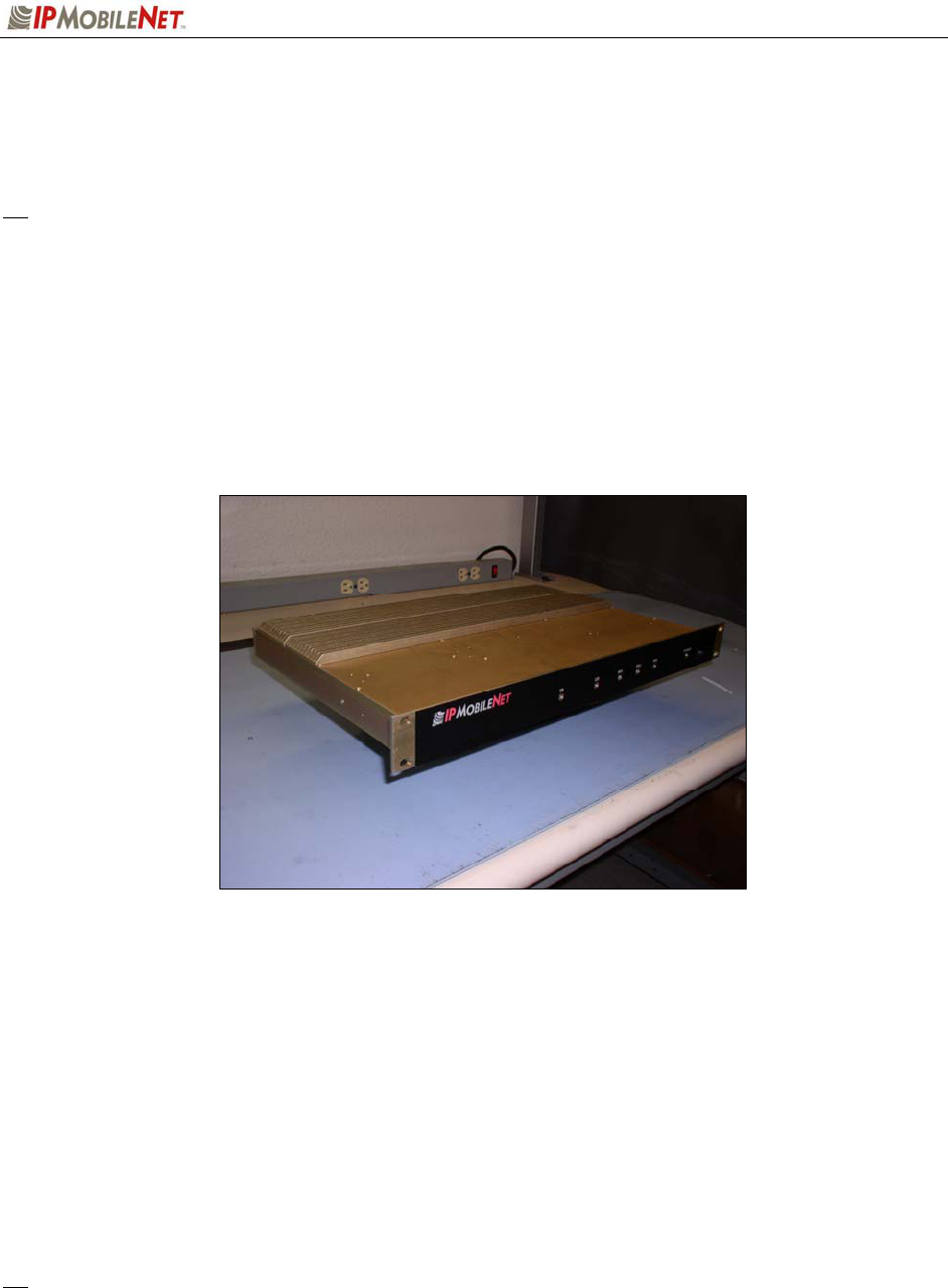
The IPSeries Base Stations are intelligent devices designed for stringent requirements of mobile data
communication systems. Intended for mounting in rack units, the base station requires very little room at
tower sites and may be connected via Serial Line Internet Protocol (SLIP) or Ethernet ports. At the
minimum, the unit requires a 13.8 VDC power supply, an antenna system, and a high-speed data
connection to an Internet Protocol Network Controller (IPNC) system to operate. The base station is
typically teamed up with a Power Amplifier (PA) and third-party system components such as antennae,
preamplifiers, preselectors, filters, and combiners.
Product Functionality
The base station utilizes a high-performance DSP to modulate/demodulate 4 to 16-level Frequency-Shift
Keying (FSK) modem for 25 kHz channel spacing, a multi-layered approach to signaling reliability,
including patented multi-receiver Intelligent Diversity Reception, dynamic scrambling, data interleaving
for burst error protection, Forward Error Correction (FEC), and Viterbi soft-decision algorithms.
The IPSeries High Speed Base Station technology includes IPMobileNet’s Diversity Reception (DR)
capability. Diversity Reception reduces the number of fades and the effects of multi-path reception. With
the use of three (3) antennae, mounted as far apart as possible on the base station tower, the Diversity
Reception System (DRS) minimizes the effects of fading. One of the antennae is likely to receive a viable
signal while the others may not. DRS minimizes fading effects by comparing the signal levels from the
three (3) antennae, and selecting the strongest signal.
Diversity is most effective when the vehicle using an IPSeries Mobile Radio is in motion.
SECTION 1: OVERVIEW
637246.DOC Page 5
External Features
The base station technology is enclosed in a sturdy aluminum case. The external features consist of a
series of connectors in the rear of the base station and light emitting diodes in the front of the base
station, as described in this section.
S The product warranty becomes void if an uncertified or unauthorized individual removes the base
station cover.
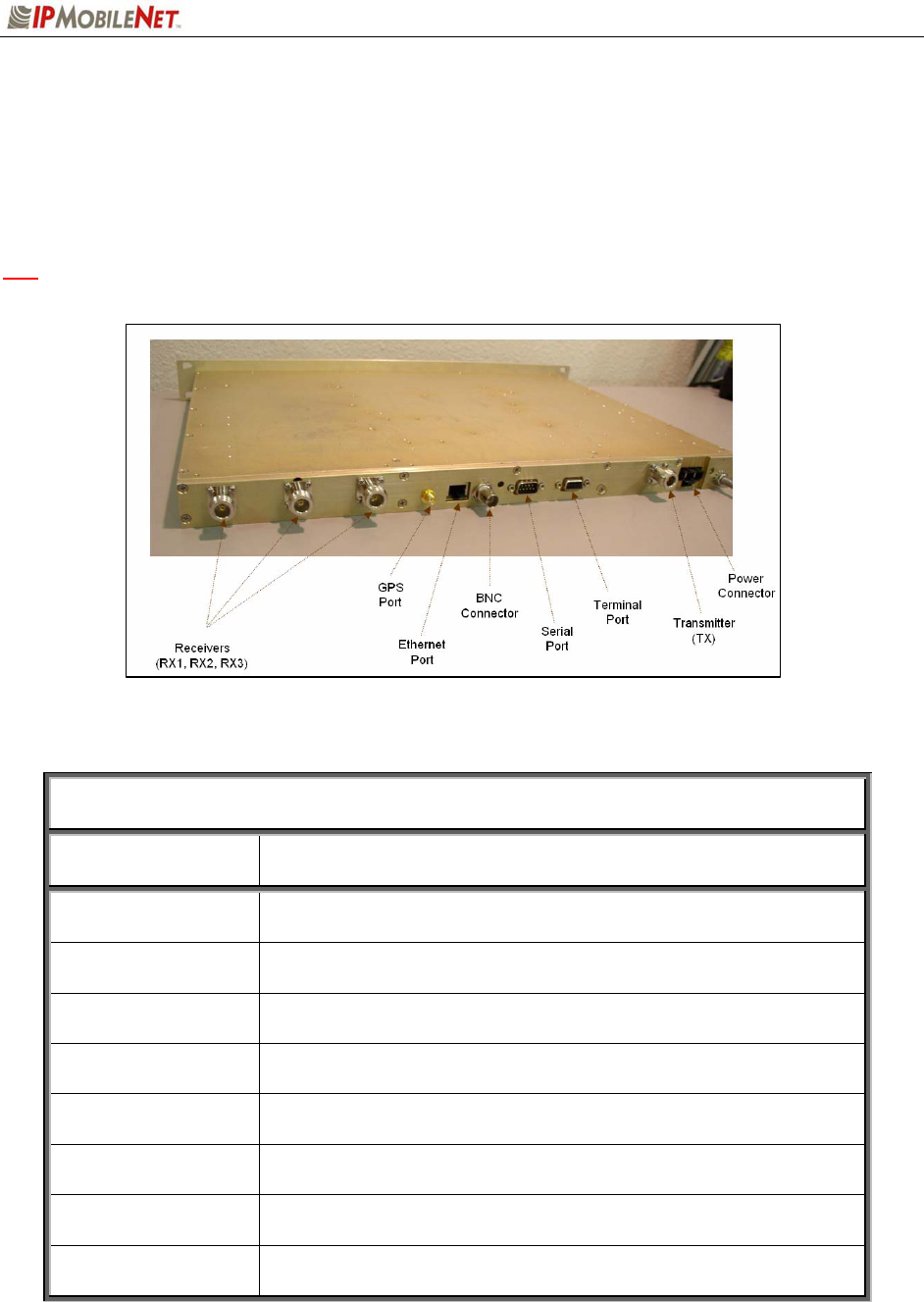
The base station’s rear external features consist of the following connectors and ports:
TABLE 1: EXTERNAL FEATURES (Rear)
FEATURE DESCRIPTION
TX Transmitter antenna connection
RX1/RX2/RX3 Receivers 1, 2, and 3 antenna connections
GPS Port GPS antenna (SMA) connector
BNC Bayonet Neill Concelman connector used for measuring receiver
sensitivity.
Power Connector 13.8 VDC base station power connector
Serial Port 1 (DB9M) RS232 Serial Line Internet Protocol (SLIP) interface port (115K)
Terminal Connection
(DB9F)
ANSI/TTY Terminal Connection (used for programming)
(9600 bps, no parity, 8-databits, 1-stop bit)
Ethernet Port RJ45 Ethernet 10 Base T interface port
SECTION 1: OVERVIEW
637246.DOC Page 6
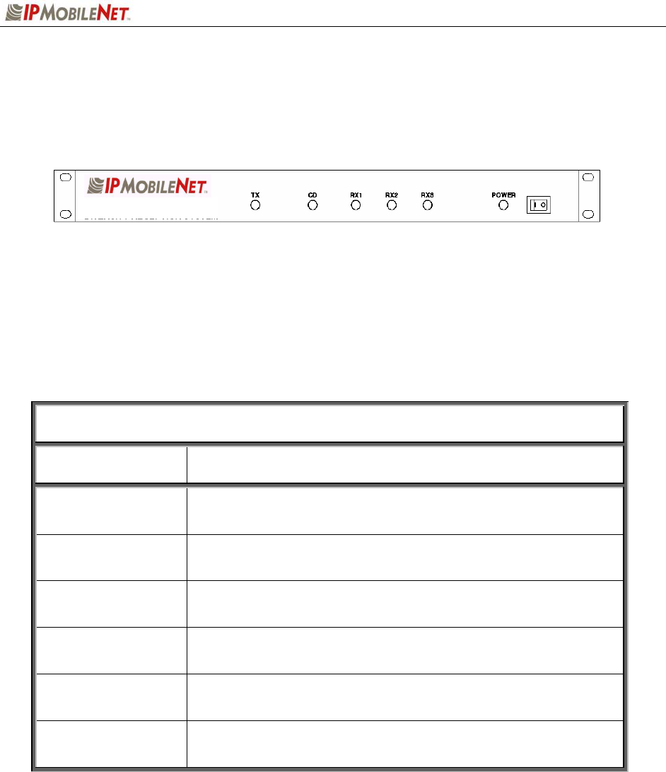
The base station’s front external features consist of six (6) LED (light emitting diodes) indicators defined
as follows:
TABLE 2: EXTERNAL FEATURES (Front)
LED Name When lit….
TX Indicates that transmission is in progress
CD Carrier detect indicates an RF message is detected
RX1 Indicates that receiving is in progress on Receiver 1
RX2 Indicates that receiving is in progress on Receiver 2
RX3 Indicates that receiving is in progress on Receiver 3
POWER Indicates the base station is powered on
SECTION 2: BASIC NETWORK CONFIGURATION
637246.DOC Page 7
Basic Network Configurations
This section provides basic network connection samples to help the user better understand some of the
possibilities in setting up their respective systems. Each organization’s configuration will differ based on
its own system requirements, equipment, backhaul, etc.
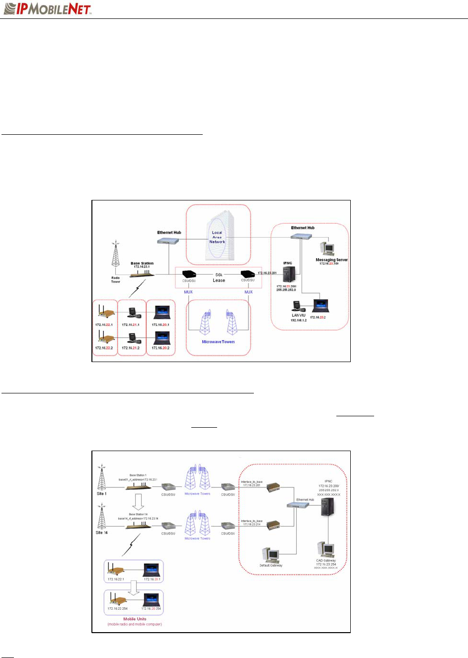
Basic Network Connection to an Existing LAN
The following figure depicts a basic network connection for an existing Local Area Network (LAN)
inclusive of one (1) Internet Protocol Network Controller (IPNC), one (1) base station, and multiple mobile
radios, voice interface units (VIU), and mobile computers. It also includes other equipment such as a LAN
VIU and a messaging server.
Basic Network Connection with a Range of Base Stations
The following figure depicts a basic network connection for a network inclusive of one (1) Internet
Protocol Network Controller (IPNC) and a range of base stations, mobile radios, mobile computers, and
additional components that interface with this sample system setup.
For serial connectivity to Ethernet only systems, please refer to the IPTurbo Converter Quick
Reference Guide (IPMN p/n: 516.80496.QR) on the Production Documentation CD (IPMN p/n:
480.0001.001).
SECTION 3: PRODUCT SETUP AND PRELIMINARY TESTING
637246.DOC Page 8
Base Station Setup
Intended for rack unit configuration, the base station can be installed in an existing rack or assembled into
a rack of its own.
Rack Unit Mounting
The table below lists the required components for a base station setup.
TABLE 3: BASE STATION COMPONENTS REQUIRED FOR INSTALLATION
QTY DESCRIPTION
1 Frequency appropriate IPSeries Base Station
1 Ethernet cable
1 5’ DC power input cable with connector
4 RF coaxial cables (may require an additional cable if connecting the base station to a
power amplifier)
SECTION 3: PRODUCT SETUP AND PRELIMINARY TESTING
637246.DOC Page 9
Preliminary Testing
This section provides a functional preliminary test for the base station prior to installation. It is used to
determine the condition of the new base station prior to placing into service. If the base station is non-
functional after completing this test, refer to Chapter 6: Customer Support.
This section applies to all base station frequency ranges.
Checklist of Required Material
The following checklist provides a list of tools required to perform this preliminary test procedure.
TABLE 4: CHECKLIST OF REQUIRED EQUIPMENT FOR PRELIMINARY TESTING OF A BASE
STATION
1
Calibrated Base Station System – Consisting of the following components:
(1) Frequency appropriate IPSeries Base Station
(2) Desktop or laptop configured as an Internet Protocol Network Controller (IPNC)
(3) Corresponding IPSeries Mobile Radio tuned to Base Station frequencies (i.e.: if an
IPB138 base, use IP138 mobile)
(4) Desktop or laptop with two (2) available serial ports with Microsoft Windows 98 or
higher, IPMobileNet Dial-Up Networking, IPMessage software, and HyperTerminal for
base station installed
(5) Base Station power cable
2 DC power supply with ammeter, with the appropriate volts, see page 7 Current Consumption
for each base station (Astron VS12M or equivalent)
3 Six (6) antennae (generic mag mounts) tuned to frequency of transceiver
Serial Base Station Interface
No. Requirement 9
1 DB9 RS232 serial cable
2 IPTurbo Converter (IPMN p/n: 900.00012.01)
3 IPTurbo Converter Reference Manual (IPMN p/n: 516.80496.REF)
Ethernet Base Stations Interface
No. Requirement 9
1 Ethernet RJ45 Cable
2 Ethernet Cable

SECTION 3: PRODUCT SETUP AND PRELIMINARY TESTING
637246.DOC Page 10
Preliminary Test Procedure
Perform the following initial setup to prepare the base station for preliminary test:
Step 1 Connect the antenna to the base station’s TX port.
Step 2 Connect the base station to the 13.8 VDC power supply.
Step 3 Power on the base station and verify that the LED’s illuminate and the power LED on the
front panel remains illuminated.
Step 4 Verify that the base station DC-supply current is <1.2 Amps.
Step 5 For the ideal Serial or Ethernet setup please refer to the IPTurbo Converter Reference
Manual (IPMN p/n: 516.80496.REF) available on the Product Documentation CD
enclosed with this product.
Step 6 Connect the antenna to the mobile radio.
Step 7 Power on the mobile radio.
Step 8 Recycle the base station power.
Step 9 Connect the antennae to the base station’s RX1.
Step 10 Verify that the RX1 and CD LED’s are illuminated when the mobile radio is attempting to
connect. Repeat steps 9 and 10 with RX2 and RX3.
Step 11 From the mobile PC, open the DOS prompt, then ping the IPNC with the following
command:
ping 172.16.23.200 (replacing with the appropriate IPNC IP address).
Press [ENTER] and verify that the IPNC responds to the ping request. Also verify that
the base station carrier detect (CD) LED is lit followed by the TX LED.

SECTION 4: PRODUCT INSTALLATION
637246.DOC Page 11
Installation Overview
This chapter provides the basic setup involved in the installation process of an IPSeries High Speed Base
Station. For backhaul requirements, refer to Appendix A of this document.
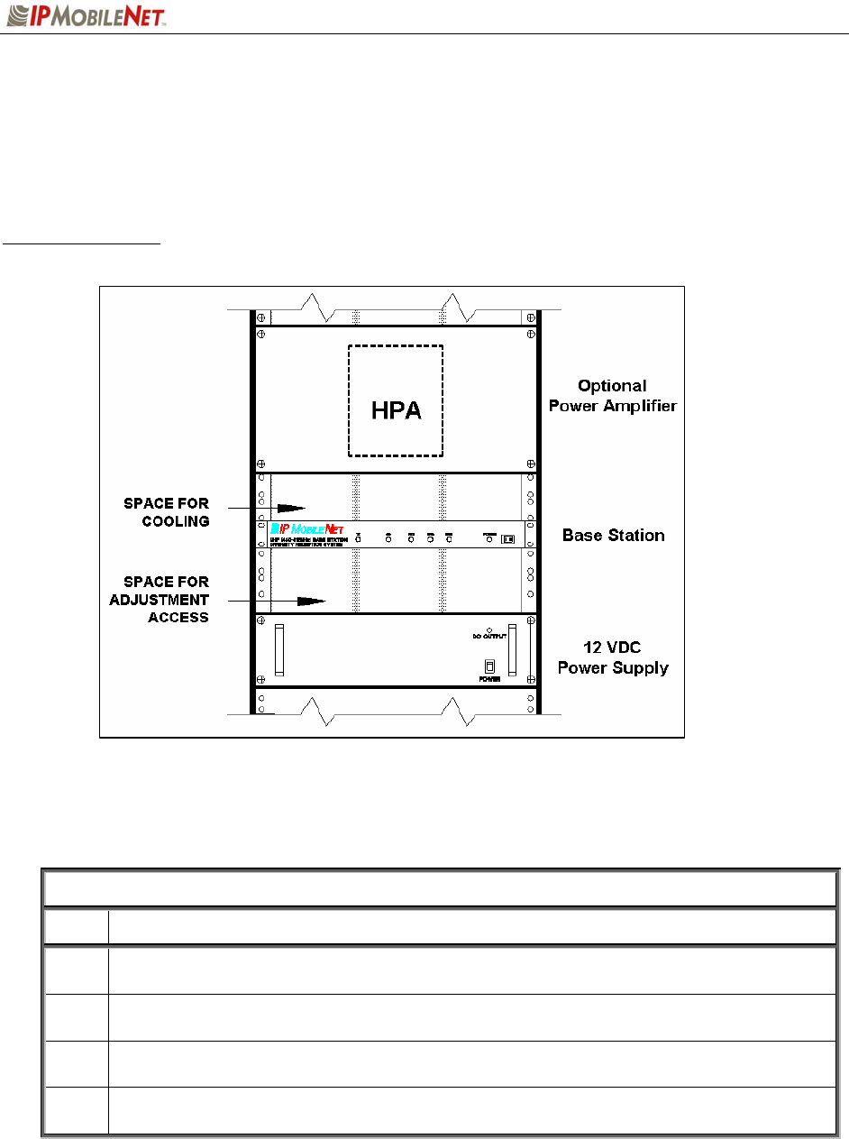
S Standard considerations such as air flow clearance above the base station for heat dissipation
and ensuring adequate space exists behind the base station for the routing of cables are of
primary importance.
A minimum clearance of 1 rack space is recommended for natural convection cooling.
Adjustment points are available through holes in the base station’s bottom cover. Sufficient
space below the base station should exist to facilitate adjustments.
Coax, power, and interface cabling service lengths with neat routing will make the removal and
replacement of the base station easier for functional testing and maintenance purposes.
To prevent injury and damage to the base station, exercise extreme caution throughout the
installation process and follow the reminders listed below.
Follow safety precautions for handling rack unit installations.
Do not alter the components listed in the Installation Requirements section, unless
substituions are noted within this chapter.

SECTION 4: PRODUCT INSTALLATION
637246.DOC Page 12
Installation Instructions
If setting up a new rack unit, make sure to complete the rack unit setup according to the
Manufacturers’ instructions.
Base Station Installation into the Rack Unit
Receiver and Transmitter Connections
To connect the base station, perform the following steps:
Step 1 Connect the RF coaxial cable to Receiver 1 (RX1) on the back of the base station.
Step 2 Route the cable neatly toward the top of the rack. Allow a little slack in the cable to avoid
accidental disconnection.
Step 3 Connect the RF coaxial cable to Receiver 2 (RX2) on the back of the base station.
Step 4 Route the cable neatly toward the top of the rack. Allow a little slack in the cable to avoid
accidental disconnection.
Step 5 Connect the RF coaxial cable to Receiver 3 (RX3) on the back of the base station.
Step 6 Route the cable neatly toward the top of the rack. Allow a little slack in the cable to avoid
accidental disconnection.
For clear identification for troubleshooting and/or maintenance activities, avoid crossing the
coaxial cables.
Step 7 Connect the RF coaxial cable to the Transmitter (TX) connection on the back of the base
station.
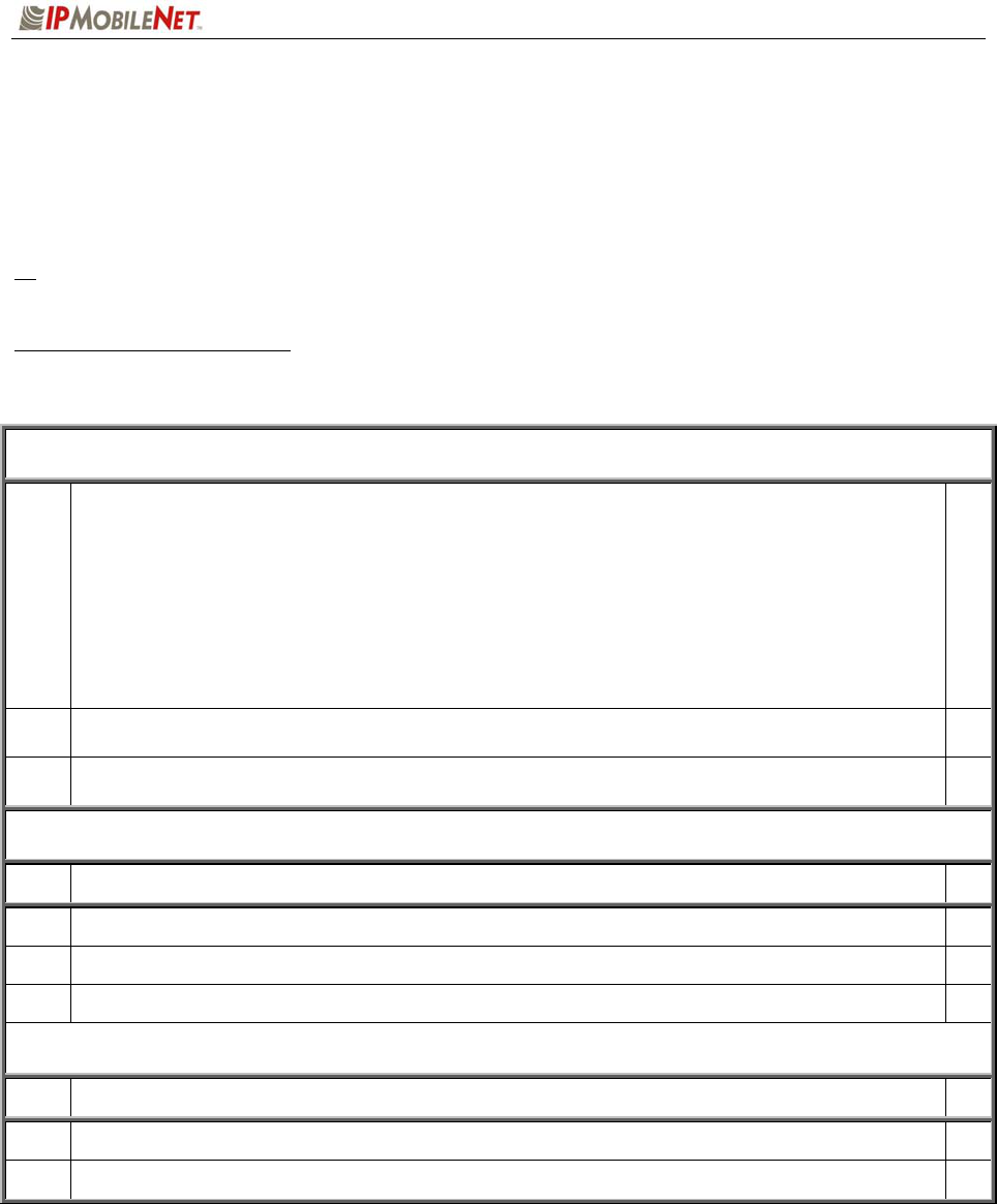
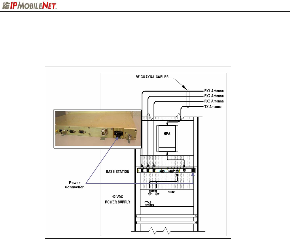
Step 8 If connecting to a power amplifier (as shown in the figure below), connect the cable from the
base station to the power amplifier via the Transmitter (TX) connection.
If not connecting to a power amplifier, skip to Step 11.
Step 10 If a power amplifier is used, connect an RF coaxial cable to the output port of the power
amplifier.
Step 11 Route the cable neatly toward the top of the rack. Allow a little slack in the cable to avoid
accidental disconnection.
Step 12 To perform the RX1, RX2, RX3, and TX antenna connections, refer to the Typical Antenna
Configuration section in this chapter.
SECTION 4: PRODUCT INSTALLATION
637246.DOC Page 13
Figure 8: Base Station Mounting and Connection in the Rack Unit (Rear View)
SECTION 4: PRODUCT INSTALLATION
637246.DOC Page 14
Single Base Station Configuration
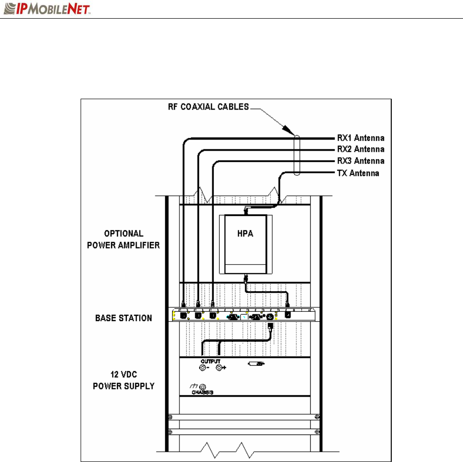
Figure 9: Base Station Ethernet Connection
To connect a single base station, perform the following steps:
Step 1 Plug in the Ethernet cable into the Ethernet port on the base station (as shown in the figure
above).
Step 2 Route and plug in the other end of the Ethernet cable to an Ethernet switch or router.
Step 3 Route and plug in another Ethernet cable from the Ethernet switch or router to the Ethernet
port of the Internet Protocol Network Controller (IPNC).
If connecting to a Serial backhaul, an IPMobileNet IPTurbo Converter is required. For
connection instructions, refer to the IPTurbo Converter Reference Manual (IPMN p/n:
516.80496.REF) available on the Product Documentation CD provided with this product.
Multiple Base Station Configurations
To connect multiple base stations, perform the following steps:
Step 1 Plug in the Ethernet cables to the back of each base station (as shown in the figure above)
and route according to selected setup. Refer to the IPTurbo Converter Quick Reference
Guide (IPMN p/n: 516.80496.QR) for setup instructions and scenarios.
Step 2 Route and plug in the Ethernet cables to an IPMobileNet’s Internet Protocol Network
Controller (IPNC) via the hardware as defined by the organization’s configuration.
If connecting to a serial backhaul, an IPMobileNet IPTurbo Converter is required. For
connection instructions, refer to the IPTurbo Converter Reference Manual (IPMN p/n:
516.80496.REF).
SECTION 4: PRODUCT INSTALLATION
637246.DOC Page 15
Typical Antenna Configuration
Base station antenna configurations may vary from site to site depending on the type of mounting
structure, the presence of existing antennae, mounting structure loading limitations, etc. The following
information is provided as a guideline for a typical scenario.
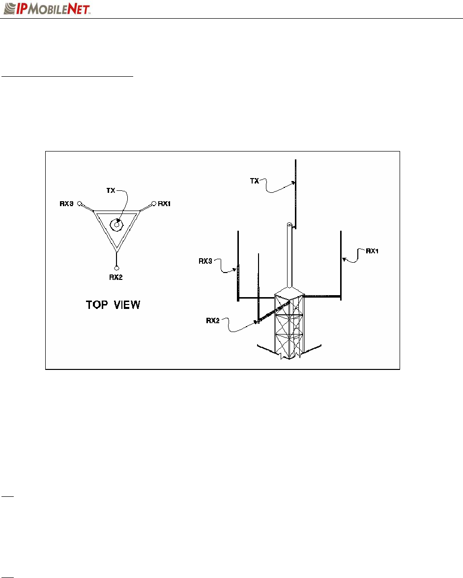
Figure 10: Typical Antenna Configuration
An optimal antenna mounting configuration is shown in the figure above. The transmit antenna and
receive antennae are located at different elevations. This vertical separation provides the greatest
degree of isolation between transmit and receive antennae. The three (3) receive antennae are mounted
at the same elevation and are oriented in a 120 degree triangular pattern. A triangular orientation of the
receive antennae provides optimal diversity performance in an omnidirectional pattern.
The greater the separation between receive antennae, the greater the diversity gain; therefore,
the distance between antennae should be made as great as is practical.
In the event only two (2) receive antennae are used (i.e. a dual receiver diversity reception system), the
receive antennae should be mounted in a broadside orientation with respect to the radio coverage area.
To prevent the antenna’s radiation pattern from becoming distorted, the immediate area
surrounding each antenna should be kept free from conductive objects (i.e. other antennae, guy
wires, or the tower structure itself). The amount of clear area required to prevent pattern distorion
is equal to the antenna’s near-field exclusion.

SECTION 4: PRODUCT INSTALLATION
637246.DOC Page 16
Near-Field Exclusion Zone
The near-field exclusion zone (NFEZ) is the required distance between antennae to any other surfaces to
improve transmit and receive performance. The large radio frequency field that builts up around the
antenna upon transmitting is essential for proper data transmission. It can be severely corrupted by metal
objects in the NFEZ. As seen in the previous figure, the transmitting antenna is placed at the very top of
the tower especially if the base station will be required to transmit in all directions (omni-directional).
If the transmitting antenna cannot be positioned on the top of the tower and must be placed on
a tower arm, then it is important to realize that coverage will be shaded in the area behind the
tower from the anetnna. The installer must be certain that the area of desired coverage is
away from the tower and not behind it.
Receiving and transmitting antennae should not be on the same plane, especially VHF and
UHF systems where the frequency splits are relatiely small. An antenna in the near-field
exclusion zone that is tuned for the same frequency as the transmitting antenna will reradiate
the signal and create unwanted effects on the transmittal signal. The receivers will be
inundated by high levels of radio frequency energy from the transmitting antenna. This is
why it is important to include vertical separation in the plan for the base station installation.
The isolation provided by 30 feet of vertical spearation can dramatically improve the
performance of the base station.
An antenna’s NFEZ can be calculated as follows:
D = 2d2
λ
Where: D is the distance to the anenna’s near field boundary
d is the antenna’s longest linear dimension (in the same units as D)
λ is the wavelength (in the same units as D)
Maximizing the distance between the receive antennae will provide maximum diversity gain and
will minimize antenna radiation pattern distortion.
SECTION 4: PRODUCT INSTALLATION
637246.DOC Page 17
Power Connection
Figure 11: Base Station Power Connection
To connect the base station power connector, perform the following steps:
Step 1 Connect the power cable to the base station power supply connection (as shown in the figure
above).
Step 2 Connect the wires to the appropriate output (+ and -) output posts on the power supply (as
shown in the figure above).
SECTION 4: PRODUCT INSTALLATION
637246.DOC Page 18
Post Installation Checklist
The following table lists the tasks that should be performed upon completing installation.
TABLE 5: POST INSTALLATION CHECKLIST
NO. CHECKLIST ITEM ;
1 Scope out the entire area setup to locate any obvious problem areas.
2 Check antenna routing for safety concerns and near-field boundary setup.
3 Use tie wraps, where possible to ensure that all cables routed in parallel are
bundled together.
4 Perform appropriate testing to ensure base station works properly.
Once installation is complete make sure the area is clear of debris that would prevent proper
airflow and ventilation.

SECTION 5: FACTORY TEST PROCEDURE
637246.DOC Page 19
Equipment List
The following table lists the equipment required to perform the B64450G25 Base Station Factory Test
Procedure.
TABLE 6: EQUIPMENT REQUIRED TO PERFORM FACTORY TEST PROCEDURE
QTY DESCRIPTION MANUFACTURER MODEL
2 PC’s (one for mobile, one for base)
Windows 9X w/
IPMessage
AVR
1 IPSeries High Speed Base Station IPMobileNet B64450G25
1 IPSeries High Speed Mobile Radio IPMobileNet M64450G25
1 Service Monitor – Communication Test Set HP 8920A or B or
equivalent
1 High Frequency Probe HP 85024A
1 Power Supply for 85024A Probe HP HP1122A
4 Channel Scope Tektronix TDS 460A
1 General Purpose Probe Scope
1 Digital Multi-Meter Fluke Tektronix Dmm91277
1 DC power supply with ammeter, 13.8V, 12
Amps or more Astron VS12M or
equivalent
1 100 watt dummy load/attenuator Pasternack PE7021-40 or
equivalent
4 UHF Antennae (generic mag mount)
1 Serial Cable DB9M – DB9F connectors
(generic) IPMobileNet 156.0245.020
1 Input/Output (I/O) Board IPMobileNet 502.80081
1 IPSeries High Speed Base Station power cable
3 Serial DB9F-DB9M Null Modem cables

SECTION 5: FACTORY TEST PROCEDURE
637246.DOC Page 20
Programming and Configuring the Base Station
This section applies to the 450 to 507 MHz frequency range of the IPSeries Base Station. Important!
The base station’s IP address must be known prior to performing the procedures in this section.
The programming procedure should be performed when it is necessary to upgrade a base station’s
Firmware or to change the operating parameters to suit client needs.
Viewing the Base Station’s Configuration Data
Step 1 At the HyperTerminal window, type in the appropriate password and press [ENTER].
Step 2 Type ? and press [ENTER]. The following example displays in the HyperTerminal
window:
Host serial = 115200,N,8,1, timeout=200
Host framing = SLIP, no split frames no status messages
tunnel = 0
TX format = new
Injection = LOW SIDE, 45MHz
channel spacing = 25000
Channel = 0
Channel Tx freq Rx freq Inj freq
Frequency=0 , 450.000000, 463.000000, 418.000000
Serial number: yyyyyyyyy
RIM address = 1
Frequency group = 1
TX quiet time = 5
Symbol sync time = 12 milliseconds, 0 extra inter-split-frame count
TX tail time = 5
Radio data rate = 19200
Max data tx time = 60 seconds
Carrier detect delay time = 1 millisecond
Station ID = ABC123
Station ID time =10 minutes
Polarity = TX+, RX+
Allow crc errors = 0
Suppress keep alive = 0
Allow base to base = 0
Timeslot status = 0
Duplicate time = 10 milliseconds
Control head grant delay = 50 milliseconds
RIM DD delay = 0 milliseconds
Retry interval = 0 milliseconds
Retry time limit = 0 milliseconds
RSSI step = 25 (=19dBm)
IPNC = 192.168.3.3
SLIP Address = 192.168.4.6
RF IP Address = 192.168.3.1
SNTP interval = 60 seconds
num timeslots = 16
timeslot period = 992ms
timeslots per voice packet = 4
noise = -128dBm
Fixed TX Delay = 0 milliseconds
Scale TX Delay = 0 microseconds

SECTION 5: FACTORY TEST PROCEDURE
637246.DOC Page 21
Adjustment / Alignment Procedures
Make appropriate notations of any items that require attention during this procedure. This information is
needed later during the repair process.
Startup
Step 1 Remove the base station cover placing the screws in a location where they will not be
misplaced.
Step 2 Connect the base station to the appropriate components.
Step 3 Power up the base station and computer. The power supply ammeter must read 1.2
amps or less with a 13.8 VDC input.
Receiver Injection
Step 1 Using the HP high frequency probe verify that the receiver injection frequency is present
at each of the three (3) receivers by monitoring the receivers R24 surface mount pad
which lies on the 50 ohm track between P1 and C43.
Step 2 Adjust R23 on the receiver injection circuit board to set the injection frequency within 10
Hz of the exact injection frequency. The amplitude of the injection frequency should read
approximately +5 dBm ±1 dBm.
Receiver
Step 1 Using the high frequency probe, monitor the 44.545 MHz second injection frequency
at U6 pin 3, adjust trimmer capacitor (C22) to the center of the oscillator’s oscillation
range. The amplitude level of pin 3 of U6 should read between +5 and +10 dBm.
Step 2 Inject an on-frequency signal at a level of –80 dBm, modulated with a 1 KHz test tone at
±5.0 KHz deviation into the receiver under test.
Step 3 Check the receiver’s sensitivity, verifying that the SINAD is 12 dB or better at a maximum
level of –119 dBm (-120 is typical).

SECTION 5: FACTORY TEST PROCEDURE
637246.DOC Page 22
Diversity Reception
Step 1 Inject an on-frequency signal at a level equal to Receiver 1 12dB SINAD level, modulated
with a 1 KHz test tone at ±5.0 KHz deviation into Receiver 1.
Step 2 While monitoring TP1 with the digital multi-meter, adjust RSSI1 low adjust potentiometer
(R12) for a reading of 0.750 VDC ±10 mV.
Step 3 Increase the amplitude of the signal by 50 dBm.
Step 4 While monitoring TP1 with the digital multi-meter, adjust RSSI1 high adjust potentiometer
(R11) for a reading of 2.75 VDC ±10 mV.
Adjustments R11 and R12 are interactive adjustments, therefore continue adjustments until the DC voltage
at TP1 is 0.750 VDC for the receiver’s 12 dB SINAD level and 2.75 VDC for a 50 dBm increase from the
receiver’s 12 dB SINAD level.
Step 5 Inject an on-frequency signal at a level equal to Receiver 2 12dB SINAD level, modulated
with a 1 KHz test tone at ±5.0 KHz deviation into Receiver 2.
Step 6 While monitoring TP2 with the digital multi-meter, adjust RSSI1 low adjust potentiometer
(R10) for a reading of 0.750 VDC ±10 mV.
Step 7 Increase the amplitude of the signal by 50 dBm.
Step 8 While monitoring TP2 with the digital multi-meter, adjust RSSI1 high adjust potentiometer
(R9) for a reading of 2.75 VDC ±10 mV.
Adjustments R9 and R10 are interactive adjustments, therefore continue adjustments until the DC voltage
at TP2 is 0.750 VDC for the receiver’s 12 dB SINAD level and 2.75 VDC for a 50 dBm increase from the
receiver’s 12 dB SINAD level.
Step 9 Inject an on-frequency signal at a level equal to Receiver 3 12dB SINAD level, modulated
with a 1 KHz test tone at ±5.0 KHz deviation into Receiver 3.
Step 10 While monitoring TP3 with the digital multi-meter, adjust RSSI1 low adjust potentiometer
(R33) for a reading of 0.750 VDC ±10 mV.
Step 11 Increase the amplitude of the signal by 50 dBm.
Step 12 While monitoring TP3 with the digital multi-meter, adjust RSSI1 high adjust potentiometer
(R35) for a reading of 2.75 VDC ±10 mV.
Adjustments R33 and R35 are interactive adjustments, therefore continue adjustments until the DC voltage
at TP3 is 0.750 VDC for the receiver’s 12 dB SINAD level and 2.75 VDC for a 50 dBm increase from the
receiver’s 12 dB SINAD level.

SECTION 5: FACTORY TEST PROCEDURE
637246.DOC Page 23
Step 13 Inject on-frequency signal at a level of –80 dBm, modulated with a 1 KHz test tone at
±5.0 KHz deviation into Receiver 1.
Step 14 While monitoring the AC voltage at TP6 adjust audio 1 AC adjustment potentiometer
(R72) for 350 mVRMS (±1 mV).
Step 15 While monitoring the DC voltage at TP6 adjust audio 1 DC adjustment potentiometer
(R57) for 2.500 VDC (±1 mV).
The audio AC and DC adjustments are interactive, therefore continue adjusting R72 for 350 mVRMS and
R57 for 2.500 VDC until further adjustments are no longer required.
Step 16 Inject on-frequency signal at a level of –80 dBm, modulated with a 1 KHz test tone at
±5.0 KHz deviation into Receiver 2.
Step 17 While monitoring the AC voltage at TP6 adjust audio 1 AC adjustment potentiometer
(R71) for 350 mVRMS (±1 mV).
Step 18 While monitoring the DC voltage at TP6 adjust audio 1 DC adjustment potentiometer
(R58) for 2.500 VDC (±1 mV).
The audio AC and DC adjustments are interactive, therefore continue adjusting R71 for 350 mVRMS and
R58 for 2.500 VDC until further adjustments are no longer required.
Step 19 Inject on-frequency signal at a level of –80 dBm, modulated with a 1 KHz test tone at
±5.0 KHz deviation into Receiver 3.
Step 20 While monitoring the AC voltage at TP6 adjust audio 1 AC adjustment potentiometer
(R53) for 350 mVRMS (±1 mV).
Step 21 While monitoring the DC voltage at TP6 adjust audio 1 DC adjustment potentiometer
(R59) for 2.500 VDC (±1 mV).
The audio AC and DC adjustments are interactive, therefore continue adjusting R53 for 350 mVRMS and
R59 for 2.500 VDC until further adjustments are no longer required.
Step 22 Adjust the carrier detect potentiometer (R74) to illuminate a level of –116 dBm.
Receive Data
Step 1 Using a calibrated mobile radio, generate uplink data messages using the X=1400,19
command in the IPMessage Utility program.
Step 2 Attach an antenna to one of the base station’s receiver ports and verify on the base
station monitor screen (HyperTerminal) that the received message data quality are
consistently 240 and higher for 1400 character messages. Repeat test for each receiver.

SECTION 5: FACTORY TEST PROCEDURE
637246.DOC Page 24
Exciter
Step 1 Using the X=1400,19 command, generate data messages so the transmit power and
frequency can be checked.
Step 2 Note the power level and then on the power amplifier circuit board adjust the
potentiometer (R3) fully counterclockwise (this will enable low power transmit operation).
Step 3 Connect the base stations’ transmit port to the HP communication test set.
Step 4 While transmitting data messages using the X=1400,19 command, adjust the following:
TCXO Y1 for minimum frequency error
R42 for ±5 KHz deviation
Transmit output power should be approximately 1mWatt. The REFMOD adjustment needs to be made
while the base station is transmitting real data messages to and from a mobile radio. This is most easily
done using the ping command to ping the IPNC from a mobile radio. This will cause the base station to
repeatedly send data messages and will facilitate the REFMOD adjustment.
Step 5 Connect the base station to the IPNC.
Step 6 Using a calibrated mobile radio operating on the base station’s channel, adjust R30 for
consistent data quality readings of 248 (as observed on the mobile radio’s attached PC
IPMessage window). Access the MSDOS prompt and ping using the following command:
>;ping 192.168.3.3 –t –l 500 –w 2000
This command will ping the IPNC continuously with a 500-character test message. Press [Ctrl]+C to
stop the ping.
Power Amplifier
Step 1 Connect the base station’s transmit port to the communication test set.
Step 2 Using the X=1400,19 command, generate data messages.
Step 3 Slowly increase the base station output power by turning the power control potentiometer
clockwise until the power noted in Step 2.
Do not exceed 40 watts output power, as this will reduce the life of the amplifier module. If the base
station uses a power amplifier, output power must be set to achieve power output specified for the
specific base station installation.
Step 4 Perform a close visual inspection of the base station paying close attention to
manufacturing related problems such as loose screws, solder practices, etc.
SECTION 6: FCC LABEL
637246.DOC Page 25
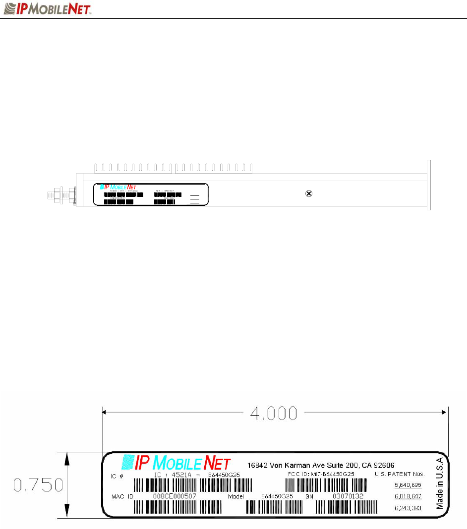
B64450G25 Base Station FCC Label Placement
B64450G25 Base Station FCC Label
Model
SNMAC ID
6,243,393
6,018,647
5,640,695
U.S. PATENT Nos.
Made in U.S.A
16842 Von Karman Av e Suite 200, CA 92606

APPENDIX A: B64450G25 TEST DATA SHEET
637246.DOC Page 26
Program and Configure the Base Station
Date
Serial Number
Firmware Revision
End User
Tester
Adjustment / Alignment Procedures
Receiver Injection
Parameter Spec Measured
Injection Frequency Error at RXINJ1(within +/- 10
Hz of exact injection frequency) +/- 100 Hz
P1 & C39 5 +/- 1 dBm
Receiver Diversity Reception Controller 1, 2 & 3
Parameter Spec Receiver 1
Measured
Receiver 2
Measured
Receiver 3
Measured
U6 Pin 4 +10 to +5 dBm
RSSI Test Point TB1-4 2.8 to 3.0 VDC
Distortion
(1 kHz Test Tone @ 5.0 kHz) 3%<
SINAD 12 dB
(1 kHz Test Tone @ 5 kHz) -119dBm >
SINAD 12 dB TP1 0.75 VDC
+/- 1 mV
SINAD +50 dB TP1 2.75 +/- 1 mV
Audio AC Amplitude
(1 kHz Test Tone @ 5 kHz
Deviation)
350 mVRMS
+/- 1mV
Audio DC Amplitude
(1 kHz Test Tone @ 5 kHz
Deviation)
2.5 VDC
+/1 1mV
Carrier Detect Light Set -116 dBm

APPENDIX A: B64450G25 TEST DATA SHEET
637246.DOC Page 27
Data Quality
Parameter Spec Measured
Receiver 1 Data Quality
(x=1400, 19 Command IPMessage Utility) 240>
Receiver 2 Data Quality
(x=1400, 19 Command IPMessage Utility) 240>
Receiver 3 Data Quality
(x=1400, 19 Command IPMessage Utility) 240>
Exciter
Parameter Spec Measured
Transmit Frequency Error
(Transmitting 1400 character test message) +/- 500 Hz
Transmit Modulation Deviation
(5.3 kHz while transmitting 1400 character test
message)
5.1 kHz to 5.3 kHz
Transmit Data Quality
(While transmitting 1400 character test message
to the base station)
240>
Transmit Power Control
Warning: Do Not exceed 40 Watts RF output power during this test
Parameter Spec RF Out RF Out Max Level set to
Output Power
(Use x=1400,19 command) 40 +/- 1 Watt
Test Check List
Test Task Completed
(9)
Attached copy of Base Station’s Firmware Settings
Visual Inspection
Copy Base Station Settings Below: