IP Mobilenet B64700G25 700/800 MHz Base Station User Manual 489287
IP Mobilenet, LLC 700/800 MHz Base Station 489287
UserManual.wiki
>
IP Mobilenet
>
B64700G25 User Manual
>
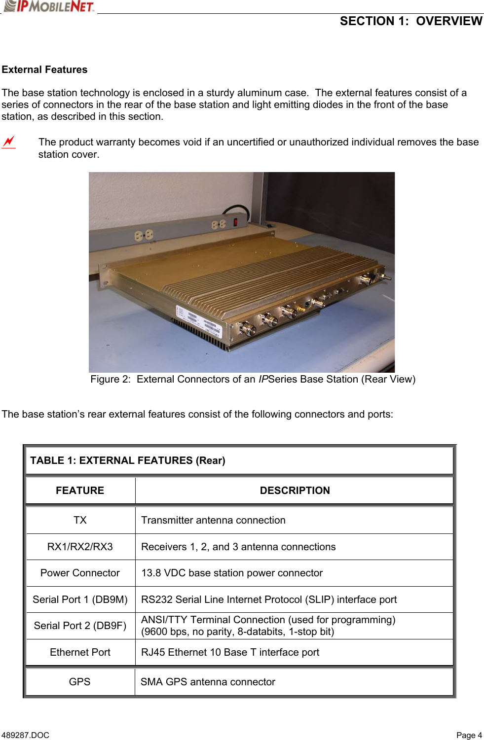
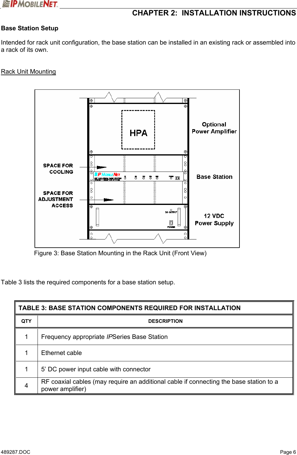
Users Manual 1
Contents
1.
Users Manual 1
2.
Users Manual 2
Users Manual 1
Navigation menu
Upload a User Manual
Namespaces
Wiki Guide
HTML
PDF
Info
Views
User Manual
Discussion / Help
Navigation