IP Mobilenet B64700G25 700/800 MHz Base Station User Manual 489287
IP Mobilenet, LLC 700/800 MHz Base Station 489287
Contents
- 1. Users Manual 1
- 2. Users Manual 2
Users Manual 1

I
IP
PS
Se
er
ri
ie
es
s
B
B6
64
47
70
00
0G
G2
25
5
7
70
00
0
M
MH
Hz
z
B
Ba
as
se
e
S
St
ta
at
ti
io
on
n
P
Pr
ro
od
du
uc
ct
t
O
Ow
wn
ne
er
r’
’s
s
M
Ma
an
nu
ua
al
l
Version Date: November 17, 2004
Document #: 516.80531.POM
Version: X1
Copyright 2004 IPMobileNet, Inc.
.
16842 Von Karman Avenue, Suite 200 Irvine, CA 92606
Voice: (949) 417-4590 Fax: (949) 417-4591
489287.DOC Page ii
Operation is subject to the following two (2) conditions: (1) this devise may not cause
interference, and (2) this device must accept any interference, including interference that may
cause undesired operation of this device.
The following U.S. Patents apply to this product:
U.S. Patent numbers 5,640,695,6,018,647,6,243,393
Information contained in this document is subject to change without notice.
All rights reserved. Reproductions, adaptations, or translation without prior written permission is
prohibited, except as allowed under copyright laws.

TABLE OF CONTENTS
489287.DOC Page 2
SECTION 1: OVERVIEW............................................................................................................................. 3
Product Description....................................................................................................................... 3
Product Functionality .................................................................................................................... 3
External Features........................................................................................................................... 4
SECTION 2: INSTALLATION INSTRUCTIONS ......................................................................................... 6
Base Station Setup ........................................................................................................................ 6
Rack Mounting Unit............................................................................................................. 6
Installation Overview ..................................................................................................................... 7
Installation Instructions................................................................................................................. 8
Interconnection Diagram..................................................................................................... 8
Base Station Installation into Rack Unit.............................................................................. 8
Single Base Station Configuration .................................................................................... 10
Multiple Base Station Configurations................................................................................ 10
Typical Antenna Configuration.......................................................................................... 11
Near-Field Exclusion Zone................................................................................... 12
Power Connection............................................................................................................. 13
Post Installation Checklist ................................................................................................. 14
SECTION 3: PROGRAMMING INSTRUCTIONS...................................................................................... 15
Overview ....................................................................................................................................... 15
HyperTerminal Setup................................................................................................................... 15
Additional Programming Needs ................................................................................................. 17
SECTION 4: FACTORY TEST PROCEDURE .......................................................................................... 18
Equipment List ............................................................................................................................. 18
Programming and Configuring the Base Station ..................................................................... 19
Adjustment / Alignment Procedure............................................................................................ 20
Startup
............................................................................................................................. 20
Receiver Injection.............................................................................................................. 20
Receiver............................................................................................................................ 20
Diversity Reception ........................................................................................................... 21
Receive Data
..................................................................................................................... 22
Exciter ............................................................................................................................. 23
Power Amplifier ................................................................................................................. 23
SECTION 5: FCC LABEL.......................................................................................................................... 24
700 MHZ Base Station FCC Label Placement ........................................................................... 24
700 MHZ Base Station FCC Label............................................................................................... 24
SECTION 6: 700 MHZ TEST DATA SHEET.............................................................................................. 25
SECTION 1: OVERVIEW
489287.DOC Page 3
Product Description
The content of this manual applies to all frequency ranges of the IPSeries Base Stations, unless
otherwise specified. This manual will note key differences between frequency ranges when
appropriate.
The IPSeries Base Stations are intelligent devices designed for stringent requirements of mobile data
communication systems. Intended for mounting in rack units, the base station requires very little room at
tower sites and may be connected via Serial Line Internet Protocol (SLIP) or Ethernet ports. The base
station circuit boards are built using surface mount technology (SMT) and through-hole components. At
the minimum, the unit requires a 13.8 VDC power supply, an antenna system, and a high-speed data
connection to an Internet Protocol Network Controller (IPNC) system to operate. The base station is
typically teamed up with a Power Amplifier (PA) and third-party system components such as antennas,
preamplifiers, preselectors, filters, and combiners.
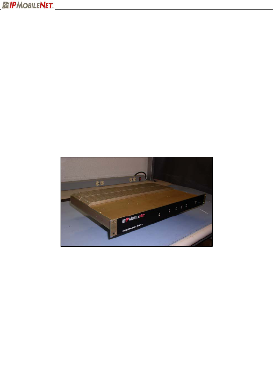
Figure 1: IPSeries Base Station External Illustration (Front View)
Product Functionality
The base station utilizes an internal high-performance 4-level Frequency-Shift Keying (FSK) wireless data
modem (19200 bps or 32000 bps) for 25 kHz channel spacing, a multi-layered approach to signaling
reliability, including patented multi-receiver Intelligent Diversity Reception, dynamic scrambling, data
interleaving for burst error protection, Forward Error Correction (FEC), and Viterbi soft-decision
algorithms.
The IPSeries Base Station technology includes IPMobileNet’s Diversity Reception (DR) capability.
Diversity Reception reduces the number of fades and the effects of multi-path reception. With the use of
three (3) antennas, mounted as far apart as possible on the base station tower, the Diversity Reception
System (DRS) minimizes the effects of fading. One of the antennas is likely to receive a viable signal
while the others may not. DRS minimizes fading effects by comparing the signal levels from the three (3)
antennas, and selecting the strongest signal.
Diversity is most effective when the vehicle using an IPSeries Mobile Radio is in motion.
SECTION 1: OVERVIEW
489287.DOC Page 4
External Features
The base station technology is enclosed in a sturdy aluminum case. The external features consist of a
series of connectors in the rear of the base station and light emitting diodes in the front of the base
station, as described in this section.
a The product warranty becomes void if an uncertified or unauthorized individual removes the base
station cover.
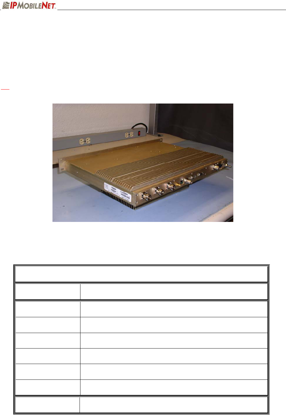
Figure 2: External Connectors of an IPSeries Base Station (Rear View)
The base station’s rear external features consist of the following connectors and ports:
TABLE 1: EXTERNAL FEATURES (Rear)
FEATURE DESCRIPTION
TX Transmitter antenna connection
RX1/RX2/RX3 Receivers 1, 2, and 3 antenna connections
Power Connector 13.8 VDC base station power connector
Serial Port 1 (DB9M) RS232 Serial Line Internet Protocol (SLIP) interface port
Serial Port 2 (DB9F) ANSI/TTY Terminal Connection (used for programming)
(9600 bps, no parity, 8-databits, 1-stop bit)
Ethernet Port RJ45 Ethernet 10 Base T interface port
GPS SMA GPS antenna connector

SECTION 1: OVERVIEW
489287.DOC Page 5
The base station’s front external features consist of six (6) LED (light emitting diodes) indicators defined
as follows:
TABLE 2: EXTERNAL FEATURES (Front)
LED Name When lit….
TX Indicates that transmission is in progress
CD Carrier detect indicates an RF message is detected
RX1 Indicates that receiving is in progress on Receiver 1
RX2 Indicates that receiving is in progress on Receiver 2
RX3 Indicates that receiving is in progress on Receiver 3
POWER Indicates the base station is powered on
CHAPTER 2: INSTALLATION INSTRUCTIONS
489287.DOC Page 6
Base Station Setup
Intended for rack unit configuration, the base station can be installed in an existing rack or assembled into
a rack of its own.
Rack Unit Mounting
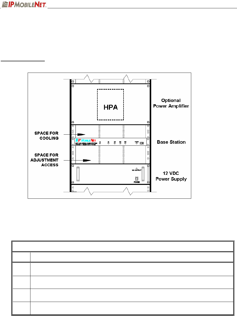
Figure 3: Base Station Mounting in the Rack Unit (Front View)
Table 3 lists the required components for a base station setup.
TABLE 3: BASE STATION COMPONENTS REQUIRED FOR INSTALLATION
QTY DESCRIPTION
1 Frequency appropriate IPSeries Base Station
1 Ethernet cable
1 5’ DC power input cable with connector
4 RF coaxial cables (may require an additional cable if connecting the base station to a
power amplifier)

CHAPTER 2: INSTALLATION INSTRUCTIONS
489287.DOC Page 7
Installation Overview
This chapter provides the basic setup involved in the installation process of an IPSeries Base
Station. For backhaul requirements, refer to Appendix A of this document.
a Standard considerations such as air flow clearance above the base station for heat
dissipation and ensuring adequate space exists behind the base station for the routing of
cables are of primary importance.
A minimum clearance of 1 rack space is recommended for natural convection cooling.
Adjustment points are available through holes in the base station’s bottom cover.
Sufficient space below the base station should exist to facilitate adjustments.
Coax, power, and interface cabling service lengths with neat routing will make the
removal and replacement of the base station easier for functional testing and
maintenance purposes.
To prevent injury and damage to the base station, exercise extreme caution throughout
the installation process and follow the reminders listed below.
Follow safety precautions for handling rack unit installations.
Do not alter the components listed in the Installation Requirements section, unless
substituions are noted within this chapter.

CHAPTER 2: INSTALLATION INSTRUCTIONS
489287.DOC Page 8
Installation Instructions
If setting up a new rack unit, make sure to complete the rack unit setup according to the
Manufacturers’ instructions.
Base Station Installation into the Rack Unit
Receiver and Transmitter Connections
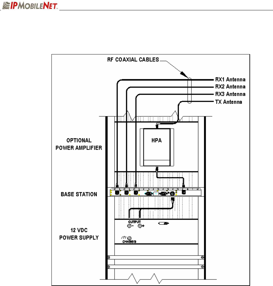
To connect the base station, perform the following steps:
Step 1 Connect the RF coaxial cable to Receiver 1 (RX1) on the back of the base station.
Step 2 Route the cable neatly toward the top of the rack. Allow a little slack in the cable to
avoid accidental disconnection.
Step 3 Connect the RF coaxial cable to Receiver 2 (RX2) on the back of the base station.
Step 4 Route the cable neatly toward the top of the rack. Allow a little slack in the cable to
avoid accidental disconnection.
Step 5 Connect the RF coaxial cable to Receiver 3 (RX3) on the back of the base station.
Step 6 Route the cable neatly toward the top of the rack. Allow a little slack in the cable to
avoid accidental disconnection.
For clear identification for troubleshooting and/or maintenance activities, avoid
crossing the coaxial cables.
Step 7 Connect the RF coaxial cable to the Transmitter (TX) connection on the back of the
base station.
Step 8 If connecting to a power amplifier (as shown in the figure below), connect the cable
from the base station to the power amplifier via the Transmitter (TX) connection.
If not connecting to a power amplifier, skip to Step 11.
Step 10 If a power amplifier is used, connect an RF coaxial cable to the output port of the
power amplifier.
Step 11 Route the cable neatly toward the top of the rack. Allow a little slack in the cable to
avoid accidental disconnection.
Step 12 To perform the RX1, RX2, RX3, and TX antenna connections, refer to the Typical
Antenna Configuration section in this chapter.
CHAPTER 2: INSTALLATION INSTRUCTIONS
489287.DOC Page 9
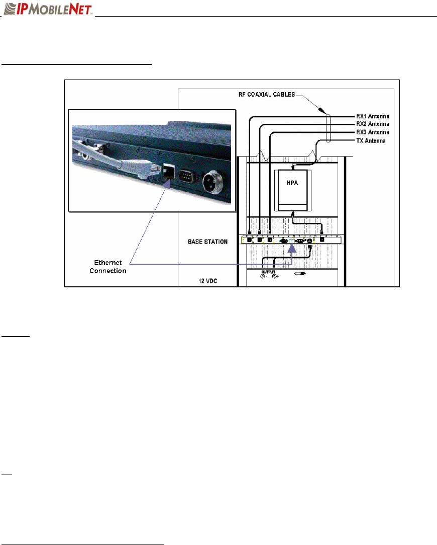
Figure 4: Base Station Mounting and Connection in the Rack Unit (Rear View)
CHAPTER 2: INSTALLATION INSTRUCTIONS
489287.DOC Page 10
Single Base Station Configuration
Figure 5: Base Station Ethernet Connection
NOTE: The base station shown in the figure only displays Ethernet connectivity and is not
display the actual 700 MHz base station.
To connect a single base station, perform the following steps:
Step 1 Plug in the Ethernet crossover cable into the Ethernet port on the base station (as
shown in the figure above).
Step 2 Route and plug in the other end of the Ethernet crossover cable to an IPMobileNet’s
Internet Protocol Network Controller (IPNC) via the hardware as defined by the
organization’s configuration.
If connecting to a Serial backhaul, an IPMobileNet IPTurbo Converter is required.
For connection instructions, refer to the IPTurbo Converter Quick Reference Guide
(IPMN p/n: 516.80496.QR) available on the Product Documentation CD provided with
this product.
Multiple Base Station Configurations
To connect multiple base stations, perform the following steps:
Step 1 Plug in the Ethernet cables to the back of each base station (as shown in the figure
above) and route according to selected setup. Refer to the IPTurbo Converter Quick
Reference Guide (IPMN p/n: 516.80496.QR) for setup instructions and scenarios.
Step 2 Route and plug in the Ethernet cables to an IPMobileNet’s Internet Protocol Network
Controller (IPNC) via the hardware as defined by the organization’s configuration.

CHAPTER 2: INSTALLATION INSTRUCTIONS
489287.DOC Page 11
If connecting to a serial backhaul, an IPMobileNet IPTurbo Converter is required. For
connection instructions, refer to the IPTurbo Converter Quick Reference Guide
(IPMN p/n: 516.80496.QR).