IP Mobilenet B64700G25 700/800 MHz Base Station User Manual 489288
IP Mobilenet, LLC 700/800 MHz Base Station 489288
Contents
- 1. Users Manual 1
- 2. Users Manual 2
Users Manual 2
CHAPTER 3: PROGRAMMING INSTRUCTIONS
Typical Antenna Configuration
Base station antenna configurations may vary from site to site depending on the type of mounting
structure, the presence of existing antennas, mounting structure loading limitations, etc. The following
information is provided as a guideline for a typical scenario.
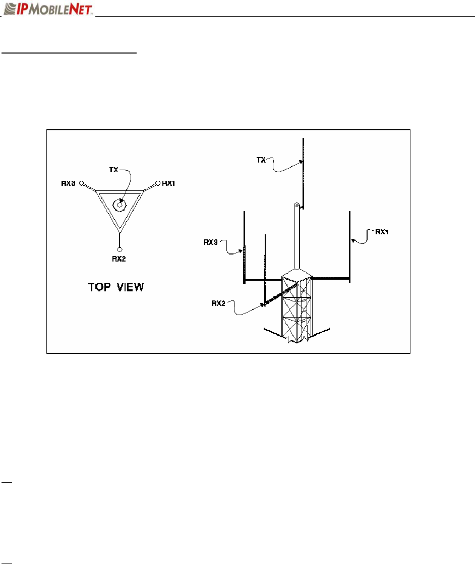
Figure 6: Typical Antenna Configuration
An otpimal antenna mounting configuration is shown in the figure above. The transmit antenna and
receive antennas are located at different elevations. This vertical separation provides the greatest degree
of isolation between transmit and receive antennas. The three (3) receive antennas are mounted at the
same elevation and are oriented in a 120 degree triangular pattern. A triangular orientation of the receive
antennas provides optimal diversity performance in an omnidirectional pattern.
The greater the separation between receive antennas, the greater the diversity gain; therefore,
the distance between antennas should be made as great as is practical.
In the event only two (2) receive antennas are used (i.e. a dual receiver diversity reception system), the
receive antennas should be mounted in a broadside orientation with respect to the radio coverage area.
To prevent the antenna’s radiation pattern from becoming distorted, the immediate area
surrounding each antenna should be kept free from conductive objects (i.e. other antennas, guy
wires, or the tower structure itself). The amount of clear area required to prevent pattern distorion
is equal to the antenna’s near-field exclusion.

CHAPTER 3: PROGRAMMING INSTRUCTIONS
Near-Field Exclusion Zone
The near-field exclusion zone (NFEZ) is the required distance between antennas to any other surfaces to
improve transmit and receive performance. The large radio frequency field that builts up around the
antenna upon transmitting is essential for proper data transmission. It can be severely corrupted by metal
objects in the NFEZ. As seen in the previous figure, the transmitting antenna is placed at the very top of
the tower especially if the base station will be required to transmit in all directions (omni-directional).
If the transmitting antenna cannot be positioned on the top of the tower and must be placed
on a tower arm, then it is important to realize that coverage will be shaded in the area behind
the tower from the anetnna. The installer must be certain that the area of desired coverage is
away from the tower and not behind it.
Receiving and transmitting antennas should not be on the same plane, especially VHF and
UHF systems where the frequency splits are relatiely small. An antenna in the near-field
exclusion zone that is tuned for the same frequency as the transmitting antenna will reradiate
the signal and create unwanted effects on the transmittal signal. The receivers will be
inundated by high levels of radio frequency energy from the transmitting antenna. This is
why it is important to include vertical separation in the plan for the base station installation.
The isolation provided by 30 feet of vertical spearation can dramatically improve the
performance of the base station.
An antenna’s NFEZ can be calculated as follows:
D = 2d2
λ
Where: D is the distance to the anenna’s near field boundary
d is the antenna’s longest linear dimension (in the same units as D)
λ is the wavelength (in the same units as D)
Maximizing the distance between the receive antennas will provide maximum diversity gain and
will minimize antenna radiation pattern distortion.
CHAPTER 3: PROGRAMMING INSTRUCTIONS
Power Connection
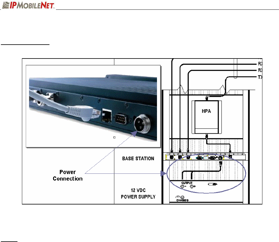
Figure 7: Base Station Power Connection
NOTE: The base station shown in the figure only displays Ethernet connectivity and is not display the
actual 700 MHz base station.
To connect the base station power connector, perform the following steps:
Step 1 Connect the power cable to the base station power supply connection (as shown in the figure
above).
Step 2 Connect the wires to the appropriate output (+ and -) output posts on the power supply (as
shown in the figure above).
CHAPTER 3: PROGRAMMING INSTRUCTIONS
Post Installation Checklist
The following table lists the tasks that should be performed upon completing installation.
TABLE 4: POST INSTALLATION CHECKLIST
NO. CHECKLIST ITEM ;
1 Scope out the entire area setup to locate any obvious problem areas.
2 Check antenna routing for safety concerns and near-field boundary setup.
3 Use tie wraps, where possible to ensure that all cables routed in parallel are
bundled together.
4 Perform appropriate testing to ensure base station works properly.
Once installation is complete make sure the area is clear of debris that would prevent proper
airflow and ventilation.
Overview
This section applies to all frequency ranges of the IPSeries Base Stations. Important! The base
station’s IP address must be known prior to performing the procedures in this section.
The programming procedure should be performed when it is necessary to upgrade a base station’s
Firmware or to change the operating parameters to suit the customer’s needs before putting into
complete operation.
HyperTerminal Setup
To communicate and access parameters from the base station, the base station must be connected to a
HyperTerminal session setup on a personal computer.
Perform the following steps to setup the base station for communication with HyperTerminal:
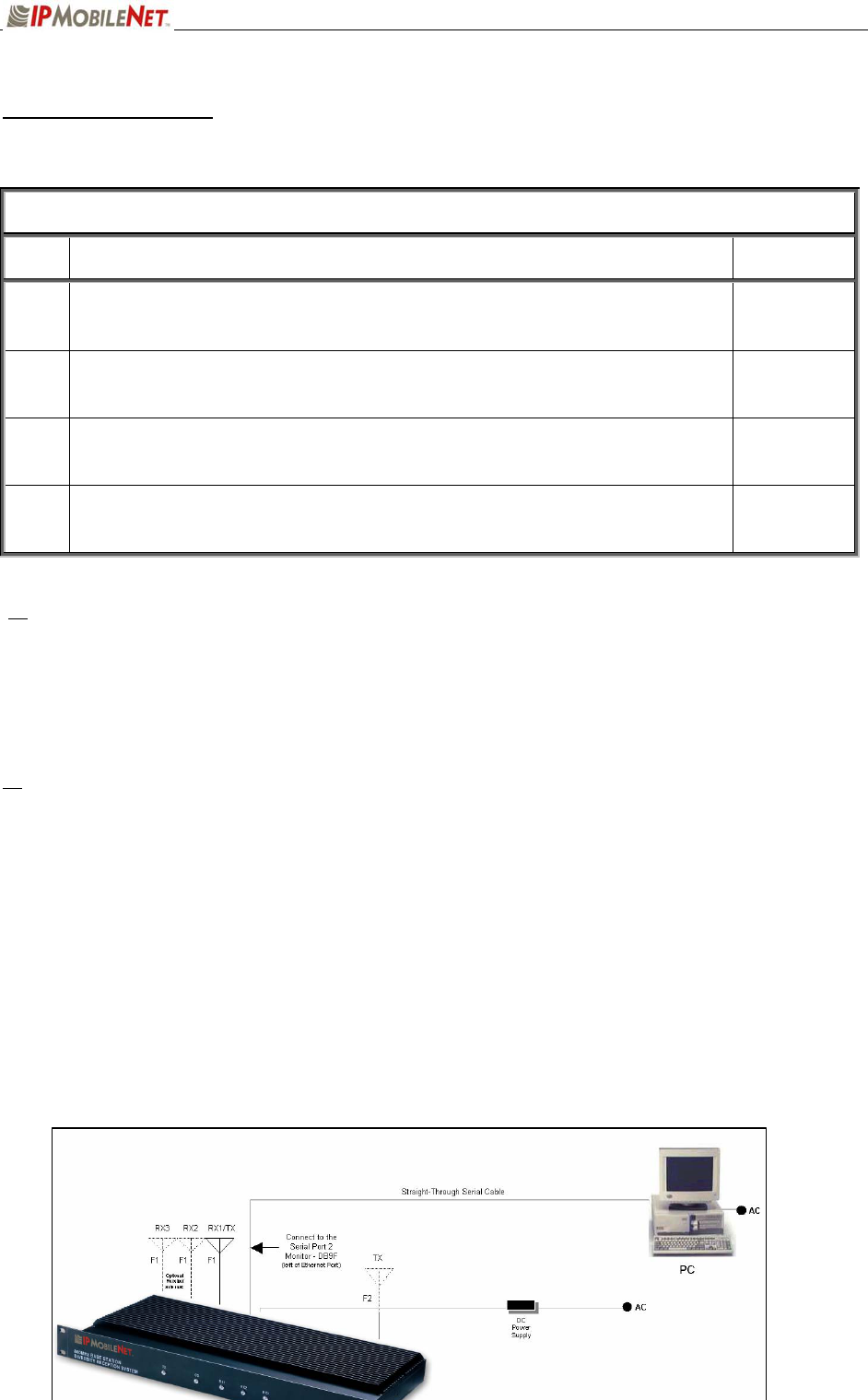
Step 1 Connect the base station and the PC as shown in the figure below.

CHAPTER 3: PROGRAMMING INSTRUCTIONS
Figure 8: Base Station-to-HyperTerminal Connection Diagram
NOTE: The base station shown in the figure only displays Ethernet connectivity and is not display the
actual 700 MHz base station.
Step 2 Power on the PC.
Step 3 Power on the base station using the front panel power switch.
Step 4 On the PC’s desktop, click on the Start button and select Accessories,
Communications, and HyperTerminal.
Step 5 At the Connection Description window enter IPMNBS and click on the OK button.
Step 6 At the Connect To window, under Connect using: select COM1 or COM2 (whichever is
available on the computer) and click on the OK button.
CHAPTER 3: PROGRAMMING INSTRUCTIONS
Step 7 At the COM Properties window make sure the properties selected are as follows:
B
its per second: 9600
D
ata bits: 8
P
arity: None
Stop bits: 1
F
low control: None
Step 8 Click on the OK button.
Step 9 Open HyperTerminal.
Step 10 Recycle the base power and HyperTerminal displays the base’s Firmware revision.
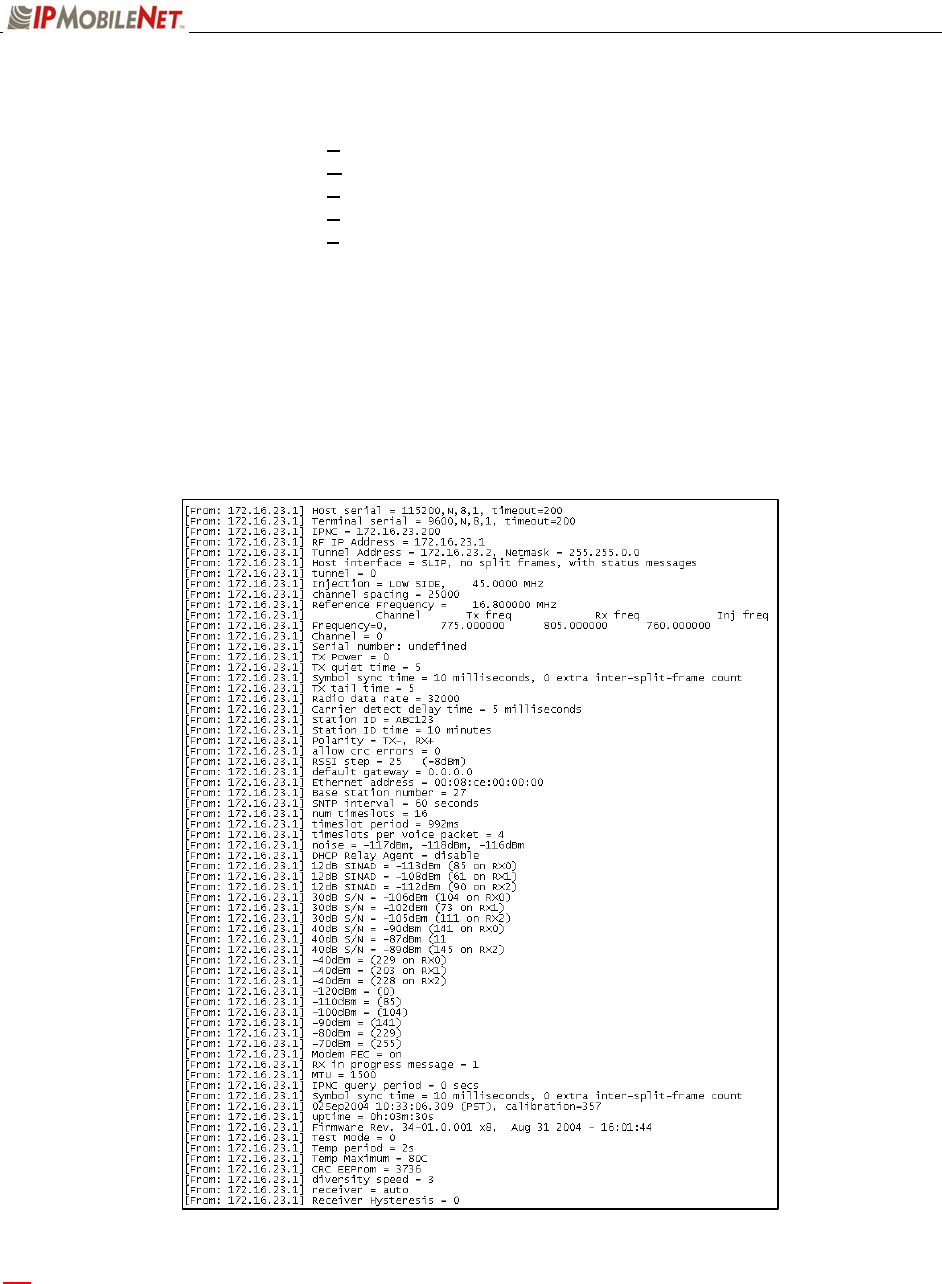
Step 11 Type in a ? in the HyperTerminal screen and press [ENTER]. This will list the Base
Station parameters, as shown in the sample below. If the cursor is not responsive, check
the cables for proper connection.
a Ensure that the calibrated base station and the mobile radio antennas are separated by
at least 10 feet. If the antennas are too close, the mobile radio receivers may overload
by the transmitters resulting in intermittent communication and high data errors.

CHAPTER 3: PROGRAMMING INSTRUCTIONS
Additional Programming Needs
Refer to the following technical notes and programming instructions and select the appropriate document
for additional functionality, programming, and setup information.
TABLE 5: ADDITIONAL PROGRAMMING DOCUMENTS
TN01-0020
Remote Firmware Updates for the IPNC and Base Station
This technical note provides instructions on how to perform remote Firmware
updates for the IPNetwork Controller and IPSeries base stations.
516.80489.UM
Internet Protocol Network Controller
Refer to the section on Fault-Tolerance for information on how the base station
operates within a fault-tolerant setup.

SECTION 4: FACTORY TEST PROCEDURE
489288.DOC Page 8
Equipment List
The following table lists the equipment required to perform the 700 MHZ Base Station Factory Test
Procedure.
CHECKLIST OF REQUIRED MATERIAL FOR
PRELIMINARY TESTING OF THE IPSeries BASE STATION
NO. REQUIRED TOOLS ;
1
Calibrated Base Station System – Consisting of the following components:
(1) Appropriate version IPSeries Base Station to be tested
(2) Desktop or laptop computer configured as an Internet Protocol Network Controller (IPNC)
(3) Corresponding IPSeries Mobile radio (If an 700 MHZ base station, use IP8 mobile radio)
(4) Desktop or laptop computer with two (2) available serial ports and Microsoft Windows 95 or
greater and IPMobileNet Dial-Up Networking, IPMessage software (SLIP2IPMN.exe), and
HyperTerminal for base station installed
2 Comm Test Set (HP 8920A or B)
3 High Frequency Probe (85024A)
4 Power Supply for 85024A Probe (HP1122A)
5 Four (4) Channel Scope (Tektronix TDS 460A)
6 General Purpose Scope Probe
7 Digital multi-meter Tektronix Fluke (DMM912 77)
8 DC power supply with ammeter, 13.8V, 12 amps or more (Astron VS12M or equivalent)
9 100-watt dummy load/attenuator (Pasternack PE7021-40 or equivalent)
10 Four (4) antennas (generic mag mounts) tuned to frequency or transceiver
11 Serial cable DB9M – DB9F connectors (generic)
12 Input/Output (I/O) Board (IPMN p/n: 502-80081)
13 IPSeries Base Station power cable specified for use with the specific base station being used
14 Three (3) serial DB9F-DB9M Null Modem cables
SECTION 4: FACTORY TEST PROCEDURE
489288.DOC Page 9
Programming and Configuring the Base Station
Important! The base station’s IP address must be known prior to performing the procedures in this
section.
The programming procedure should be performed when it is necessary to upgrade a base station’s
Firmware or to change the operating parameters to suit client needs.
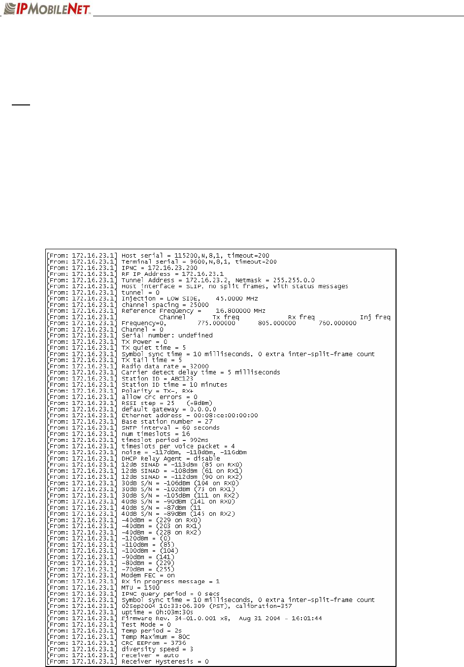
Viewing the Base Station’s Configuration Data
Step 1 At the HyperTerminal window, type in the appropriate password and press [ENTER].
Step 2 Type ? and press [ENTER]. The following example displays in the HyperTerminal
window:

SECTION 4: FACTORY TEST PROCEDURE
489288.DOC Page 10
Adjustment / Alignment Procedures
Make appropriate notations of any items that require attention during this procedure. This information is
needed later during the repair process.
Startup
Step 1 Remove the base station cover placing the screws in a location where they will not be
misplaced.
Step 2 Connect the base station to the appropriate components.
Step 3 Power up the base station and computer. The power supply ammeter must read 1.2
amps or less with a 13.8 VDC input.
Receiver Injection
Step 1 Connect the base station to gps antenna and wait until the frequencies of OCXO and
VCTCXOs are corrected and the error is below 0.1 ppm. You can check the error by
typing gpsstatus.
Step 2 Using the high frequency prob,at AL7 check the amplitude of the signal. The amplitude
of the injection frequency should read approximately 0 dBm ±1 dBm.
Receiver
Step 1 Using the high frequency probe, monitor the 44.545 MHz second injection frequency
at AU4 pin 3, adjust trimmer capacitor (C22) to the center of the oscillator’s oscillation
range. The amplitude level of pin 3 of AU4 should read between +5 and +10 dBm.
Step 2 Inject an on-frequency signal at a level of –80 dBm, modulated with a 1 KHz test tone at
±5.0 KHz deviation into the receiver under test.
Step 3 Check the receiver’s sensitivity, verifying that the SINAD is 12 dB or better at a maximum
level of –119 dBm (-120 is typical).

SECTION 4: FACTORY TEST PROCEDURE
489288.DOC Page 11
Diversity Reception
Step 1 Inject an on-frequency signal at a level equal to Receiver 1 12dB SINAD level, modulated
with a 1 KHz test tone at ±5.0 KHz deviation into Receiver 1.
Step 2 While monitoring TP1 with the digital multi-meter, adjust RSSI1 low adjust potentiometer
(R12) for a reading of 0.750 VDC ±10 mV.
Step 3 Increase the amplitude of the signal by 50 dBm.
Step 4 While monitoring TP1 with the digital multi-meter, adjust RSSI1 high adjust potentiometer
(R11) for a reading of 2.75 VDC ±10 mV.
Adjustments R11 and R12 are interactive adjustments, therefore continue adjustments until the DC voltage
at TP1 is 0.750 VDC for the receiver’s 12 dB SINAD level and 2.75 VDC for a 50 dBm increase from the
receiver’s 12 dB SINAD level.
Step 5 Inject an on-frequency signal at a level equal to Receiver 2 12dB SINAD level, modulated
with a 1 KHz test tone at ±5.0 KHz deviation into Receiver 2.
Step 6 While monitoring TP2 with the digital multi-meter, adjust RSSI1 low adjust potentiometer
(R10) for a reading of 0.750 VDC ±10 mV.
Step 7 Increase the amplitude of the signal by 50 dBm.
Step 8 While monitoring TP2 with the digital multi-meter, adjust RSSI1 high adjust potentiometer
(R9) for a reading of 2.75 VDC ±10 mV.
Adjustments R9 and R10 are interactive adjustments, therefore continue adjustments until the DC voltage
at TP2 is 0.750 VDC for the receiver’s 12 dB SINAD level and 2.75 VDC for a 50 dBm increase from the
receiver’s 12 dB SINAD level.
Step 9 Inject an on-frequency signal at a level equal to Receiver 3 12dB SINAD level, modulated
with a 1 KHz test tone at ±5.0 KHz deviation into Receiver 3.
Step 10 While monitoring TP3 with the digital multi-meter, adjust RSSI1 low adjust potentiometer
(R33) for a reading of 0.750 VDC ±10 mV.
Step 11 Increase the amplitude of the signal by 50 dBm.
Step 12 While monitoring TP3 with the digital multi-meter, adjust RSSI1 high adjust potentiometer
(R35) for a reading of 2.75 VDC ±10 mV.
Adjustments R33 and R35 are interactive adjustments, therefore continue adjustments until the DC voltage
at TP3 is 0.750 VDC for the receiver’s 12 dB SINAD level and 2.75 VDC for a 50 dBm increase from the
receiver’s 12 dB SINAD level.

SECTION 4: FACTORY TEST PROCEDURE
489288.DOC Page 12
Step 13 Inject on-frequency signal at a level of –80 dBm, modulated with a 1 KHz test tone at
±5.0 KHz deviation into Receiver 1.
Step 14 While monitoring the AC voltage at RXMOD1,pin 4 of AU6C adjust audio 1 AC
adjustment potentiometer (R72) for 350 mVRMS (±1 mV).
Step 15 While monitoring the DC voltage at RXMOD1,pin4 of AU6C adjust audio 1 DC
adjustment potentiometer (R57) for 2.500 VDC (±1 mV).
The audio AC and DC adjustments are interactive, therefore continue adjusting ARV1 for 350 mVRMS and
ARV2 for 2.500 VDC until further adjustments are no longer required.
Step 16 Inject on-frequency signal at a level of –80 dBm, modulated with a 1 KHz test tone at
±5.0 KHz deviation into Receiver 2.
Step 17 While monitoring the AC voltage at RXMOD2, pin4 of BU6C adjust audio 1 AC
adjustment potentiometer BRV1) for 350 mVRMS (±1 mV).
Step 18 While monitoring the DC voltage at RXMOD2, pin4 of BU6C adjust audio 1 DC
adjustment potentiometer (BRV2) for 2.500 VDC (±1 mV).
The audio AC and DC adjustments are interactive, therefore continue adjusting BRV1 for 350 mVRMS and
BRV2 for 2.500 VDC until further adjustments are no longer required.
Step 19 Inject on-frequency signal at a level of –80 dBm, modulated with a 1 KHz test tone at
±5.0 KHz deviation into Receiver 3.
Step 20 While monitoring the AC voltage at RXMOD3, pin4 of CU6C adjust audio 1 AC
adjustment potentiometer (CRV1) for 350 mVRMS (±1 mV).
Step 21 While monitoring the DC voltage at RXMOD3, pin4 of CU6Cadjust audio 1 DC
adjustment potentiometer (CRV2) for 2.500 VDC (±1 mV).
The audio AC and DC adjustments are interactive, therefore continue adjusting CRV1 for 350 mVRMS and
CRV2 for 2.500 VDC until further adjustments are no longer required.
Step 22 Adjust the carrier detect potentiometer (R74) to illuminate a level of –116 dBm.?
Receive Data
Step 1 Using a calibrated mobile radio, generate uplink data messages using the X=1400,19
command in the IPMessage Utility program.
Step 2 Attach an antenna to one of the base station’s receiver ports and verify on the base
station monitor screen (HyperTerminal) that the received message data quality are
consistently 240 and higher for 1400 character messages. Repeat test for each receiver.

SECTION 4: FACTORY TEST PROCEDURE
489288.DOC Page 13
Exciter
Step 1 Using the X=1400,19 command, generate data messages so the transmit power and
frequency can be checked.
Step 2 Step 3 Connect the base stations’ transmit port to the HP communication test set.
Step 4 While transmitting data messages using the X=1400,19 command, adjust the following:
RV2 for ±5 KHz deviation
Transmit output power should be approximately 1mWatt. The REFMOD adjustment needs to be made
while the base station is transmitting real data messages to and from a mobile radio. This is most easily
done using the ping command to ping the IPNC from a mobile radio. This will cause the base station to
repeatedly send data messages and will facilitate the REFMOD adjustment.
Step 5 Connect the base station to the IPNC.
Step 6 Using a calibrated mobile radio operating on the base station’s channel, adjust RV1 for
consistent data quality readings of 248 (as observed on the mobile radio’s attached PC
IPMessage window). Access the MSDOS prompt and ping using the following command:
>;ping 192.168.3.3 –t –l 500 –w 2000
This command will ping the IPNC continuously with a 500-character test message. Press [Ctrl]+C to
stop the ping.
Power Amplifier
Step 1 Connect the base station’s transmit port to the communication test set.
Step 2 Using the X=1400,19 command, generate data messages.
Step 3 Slowly increase the base station output power by turning the power control potentiometer
clockwise until the power noted in Step 2.
Do not exceed 40 watts output power, as this will reduce the life of the amplifier module. If the base
station uses a power amplifier, output power must be set to achieve power output specified for the
specific base station installation.
Step 4 Perform a close visual inspection of the base station paying close attention to
manufacturing related problems such as loose screws, solder practices, etc.
SECTION 5: FCC LABEL
489288.DOC Page 14
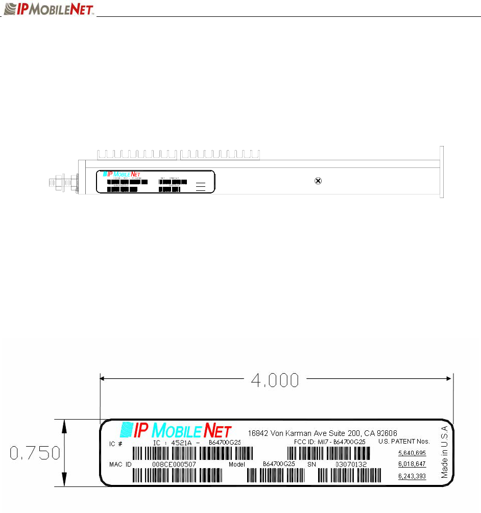
700 MHZ Base Station FCC Label Placement
700 MHZ Base Station FCC Label
Model
SNMAC ID
6,243,393
6,018,647
5,640,695
U.S. PATENT Nos.
Made in U.S.A
16842 Von Karman Av e Suite 200, CA 92606

SECTION 6: 700 MHZ TEST DATA SHEET
489288.DOC Page 15
Program and Configure the Base Station
Date
Serial Number
Firmware Revision
End User
Tester
Adjustment / Alignment Procedures
Receiver Injection
Parameter Spec Measured
Injection Frequency Error at RXINJ1(within +/- 10
Hz of exact injection frequency) +/- 100 Hz
P1 & C39 5 +/- 1 dBm
Receiver Diversity Reception Controller 1, 2 & 3
Parameter Spec Receiver 1
Measured
Receiver 2
Measured
Receiver 3
Measured
U2 Pin 4 +10 to +5 dBm
RSSI Test Point TB1-4 2.8 to 3.0 VDC
Distortion
(1 kHz Test Tone @ 5.0 kHz) 3%<
SINAD 12 dB
(1 kHz Test Tone @ 5 kHz) -119dBm >
Audio AC Amplitude
(1 kHz Test Tone @ 5 kHz
Deviation)
350 mVRMS
+/- 1mV
Audio DC Amplitude
(1 kHz Test Tone @ 5 kHz
Deviation)
2.5 VDC
+/1 1mV
Carrier Detect Light Set -116 dBm

SECTION 6: 700 MHZ TEST DATA SHEET
489288.DOC Page 16
Data Quality
Parameter Spec Measured
Receiver 1 Data Quality
(x=1400, 19 Command IPMessage Utility) 240>
Receiver 2 Data Quality
(x=1400, 19 Command IPMessage Utility) 240>
Receiver 3 Data Quality
(x=1400, 19 Command IPMessage Utility) 240>
Exciter
Parameter Spec Measured
Transmit Frequency Error
(Transmitting 1400 character test message) +/- 500 Hz
Transmit Modulation Deviation
(5.3 kHz while transmitting 1400 character test
message)
5.1 kHz to 5.3 kHz
Transmit Data Quality
(While transmitting 1400 character test message to
the base station)
240>
Transmit Power Control
Warning: Do Not exceed 40 Watts RF output power during this test
Parameter Spec RF Out RF Out Max Level set to
Output Power
(Use x=1400,19 command) 40 +/- 1 Watt
Test Check List
Test Task Completed
(9)
Attached copy of Base Station’s Firmware Settings
Visual Inspection
Copy Base Station Settings Below: