IP Mobilenet EZPRO25RF EzPro P-25 Base Station radio/repeater User Manual
IP Mobilenet, LLC EzPro P-25 Base Station radio/repeater Users Manual
Users Manual

T
TE
EC
CH
HN
NI
IC
CA
AL
L
D
DE
ES
SC
CR
RI
IP
PT
TI
IO
ON
N
A
AP
PC
CO
O
P
P2
25
5
E
EZ
ZP
PR
RO
O2
25
5
R
RF
F
–
–
I
IN
NS
ST
TA
AL
LL
LA
AT
TI
IO
ON
N
G
GU
UI
ID
DE
E

Code: Installation Guide EZPRO25 RF.d
o
INSTALLATION
GUIDE Date: 12/18/2007 Page: 2 of 21
Initial Release
Revision: 00
INDEX
1. INTRODUCTION
3
2. UNPACKING AND CHECKING
5
3. PREVIOUS CONSIDERATIONS
5
4. INFORMATION ON SAFETY AND ELECTROMAGNETIC COMPATIBILITY
5
5. EQUIPMENT DESCRIPTION
6
5.1 FRONT VIEW
7
5.2 REAR VIEW
8
5.3 MODULES
9
5.4 CABLING AND CONNECTORS
13
6. INSTALLATION GUIDE
14
6.1 LOCATION
14
6.2 POWER SUPPLY CONNECTION
14
6.3 ANTENNA CONNECTION
15
6.4 SWITCHING ON THE EZPRO25 RF
15
7. CONFIGURATION
16
8. INCIDENTS
16
8.1 ALARMS
16
8.2 ALARMS WITHOUT STATUS LEDS 19

Code: Installation Guide EZPRO25 RF.d
o
INSTALLATION
GUIDE Date: 12/18/2007 Page: 3 of 21
Initial Release
Revision: 00

Code: Installation Guide EZPRO25 RF.d
o
INSTALLATION
GUIDE Date: 12/18/2007 Page: 4 of 21
Initial Release
Revision: 00
1. INTRODUCTION
The EZPRO25 RF module (Base Station Repeater) are a modular design, high performance
products used as APCO repeaters.
The radio system is available in the 806-870Mhz frequency band.
The proper functioning of any electronic device depends on its correct use. It is therefore
recommended that the instructions in this manual be followed.

Code: Installation Guide EZPRO25 RF.d
o
INSTALLATION
GUIDE Date: 12/18/2007 Page: 5 of 21
Initial Release
Revision: 00
2. UNPACKING AND CHECKING
The following elements are supplied in the box:
EZPRO25 RF
2 cables SMB RF
Installation manual
The equipment is supplied with all the modules already assembled in the rack and with
the RF cables connected. The modules in the basic configuration are: Control (RCPU P25),
Transmitter (RTX P25), power module (RPA P25), Receiver (RRX P25) and the power supply module
(RPS P25).
IMPORTANT: if any of these elements is missing or damaged, contact your dealer and / or
installer.
3. PREVIOUS CONSIDERATIONS
This manual contains information on instructions for installation, maintenance and use. Read
the following pages before using this equipment.
It is inadvisable to switch on the equipment without having previously connected the antenna or, in
case of the EZPRO25 RF, the 50Ω load to the TNC connector. Doing so may seriously damage the
equipment and even cause irreparable damage to the transmitter circuits. It is important to use an
antenna adjusted to the work frequency.
4. INFORMATION ON SAFETY AND ELECTROMAGNETIC COMPATIBILITY
The equipment has been designed according to the following standards:
ETSI ETS 300 392-2 - V2.5.2 (2005-11)
ETSI ETS 300 394-1 - V2.4.0 (2005-10)
ETSI EN 301 489-18 - V1.3.1 (2002-08)
EN 60950-1 - 2001
EN 60950-1:2001/A11:2004
EN 60215-1989
EN 60215:1989/A1:1992
EN 60215:1989/A2:1994

Code: Installation Guide EZPRO25 RF.d
o
INSTALLATION
GUIDE Date: 12/18/2007 Page: 6 of 21
Initial Release
Revision: 00
These standards ensure the essential requirements established in article 3 of directive
1999/5/CE.
In any case, take the following points into consideration:
Most electronic equipment is susceptible to electromagnetic interference if it is not
duly protected. If the EZPRO25 RF is placed near unprotected electronic devices,
they may malfunction.
The EZPRO25 RF must not transmit without its antenna connected or, in case of the
EZPRO25 RF, without the 50Ω load in the TNC connector.
When installing the antenna, follow the guidelines for exposure of the human body to
high and low frequency electromagnetic fields. Follow the supplier’s / manufacturer’s
instructions.
Burns may be suffered if the antenna connector output of the power module (RPA
P25) is touched by bare skin when the EZPRO25 RF are transmitting with the
antenna disconnected.
Take care when handling the EZPRO25 RF. It has sharp edges, which may cut if
handled incorrectly.
Maintenance and repair of these repeaters must be carried out by qualified personnel
only.
Connect the EZPRO25 RF chassis to the earth intake in the cabinet where it is to be
installed.
Switch off the EZPRO25 RF before inserting/removing any of its modules.
!
Code: Installation Guide EZPRO25 RF.d
o
INSTALLATION
GUIDE Date: 12/18/2007 Page: 7 of 21
Initial Release
Revision: 00
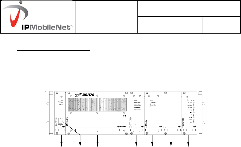
5. EQUIPMENT DESCRIPTION
5.1 FRONT VIEW
♦ EZPRO25 RF
1.- RPS P25 (Repeater Power Supply)
2.- RPA P25 (Repeater Power Amplifier)
3.- RTX P25 (Repeater Transmitter)
4.- RRX P25 (Repeater Receiver)
5.- Option RRX2 P25/BSYNC P25 ( Repeater Receiver 2 / EZPRO25 RF Synchronism)
6.- RCPU P25 (Repeater Control Processing Unit)
7
1 2 3 4 5 6
Code: Installation Guide EZPRO25 RF.d
o
INSTALLATION
GUIDE Date: 12/18/2007 Page: 8 of 21
Initial Release
Revision: 00
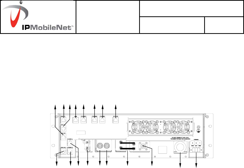
5.2 REAR VIEW
♦ EZPRO25 RF
24
23
22
21
20 19
18
17
16 15 14 9
10
11
12
13 8
25

Code: Installation Guide EZPRO25 RF.d
o
INSTALLATION
GUIDE Date: 12/18/2007 Page: 9 of 21
Initial Release
Revision: 00
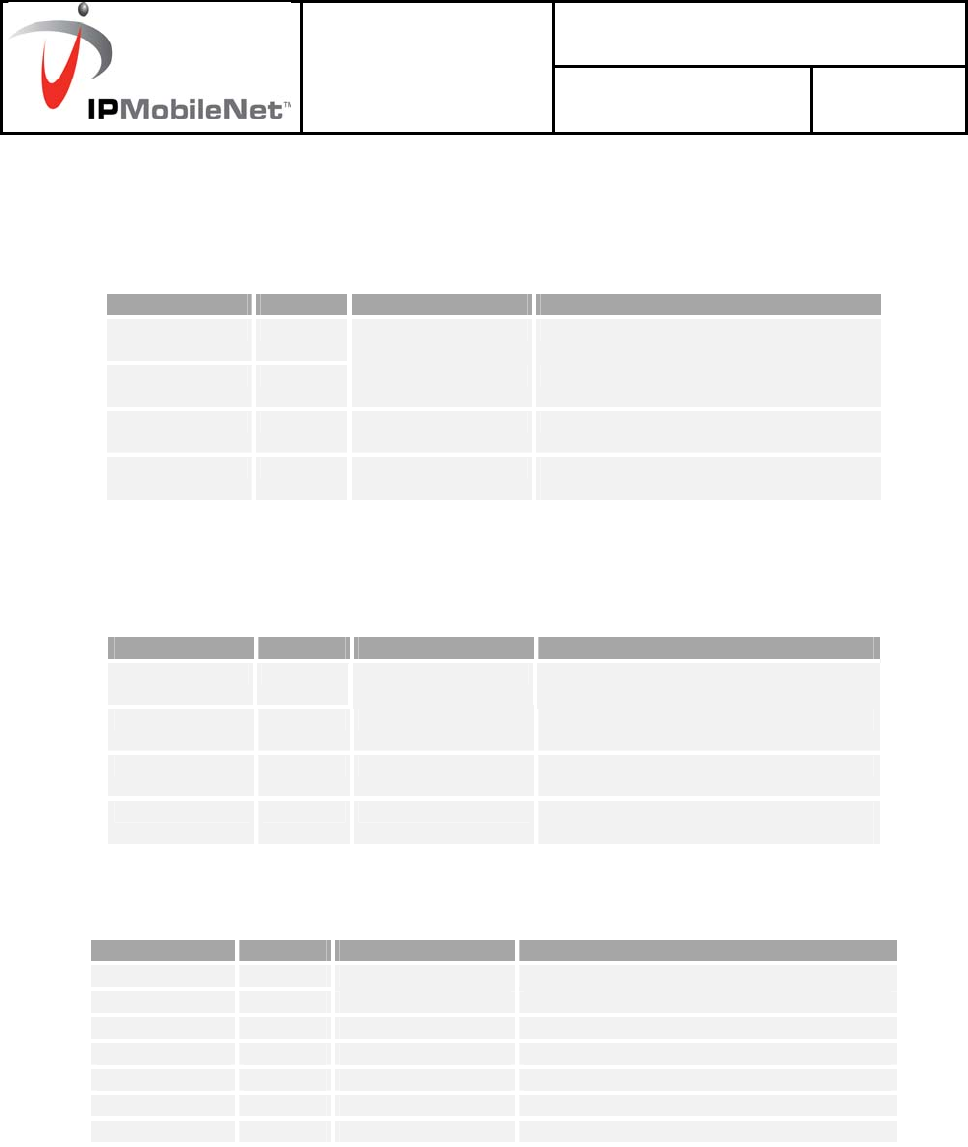
5.3 MODULES
1. RPS P25 (REPEATER POWER SUPPLY)
LEDs to indicate module status.
LED TYPE NORMAL
STATUS FUNCTIÓN
SUPPLY Green On There are 26.4V at the RPS
P25 input
24V or 26.4V Green On There are 26.4V at the RPS
P25 output
13.2V Green On There are 13.2V at the RPS
P25 output
Power on switch (Ref. 7): ON/OFF switch to connect to and disconnect from the EZPRO25
RF
2. RPA P25 (REPEATER POWER AMPLIFIER)
LEDs to indicate module status.
LED TYPE NORMAL
STATUS FUNCTIÓN
ON Green On Power supply correct
TX POWER Green On Module transmitting
3. RTX P25 (REPEATER TRANSMITTER)
LEDs to indicate module status.
LED TYPE NORMAL
STATUS FUNCTIÓN
ON Green On Power supply correct
REF. ERROR Red Off Failure in the 10 MHz reference
INT. ERROR Red Off Internal failure
BBSR
ERROR Red Off Communication failure with the
RCPU P25 module
RPA ERROR Red Off RPA P25 failure
RPW ERROR Red Off Reflected power failure

Code: Installation Guide EZPRO25 RF.d
o
INSTALLATION
GUIDE Date: 12/18/2007 Page: 10 of 21
Initial Release
Revision: 00
Code: Installation Guide EZPRO25 RF.d
o
INSTALLATION
GUIDE Date: 12/18/2007 Page: 11 of 21
Initial Release
Revision: 00
4. RRX P25 (REPEATER RECEIVER)
LEDs to indicate module status.
LED TYPE NORMAL STATUS FUNCTIÓN
ON Green On Power supply correct
REF. ERROR Red Off Failure in the 10 MHz reference
INT. ERROR Red Off Internal failure
BBSR ERROR Red Off Communication failure with the RCPU
P25 module
5. SLOT OPTION: RRX2 / BSYNC (REPEATER RECEIVER 2/ BSR SYNCHRONISM)
LEDs to indicate the status of option RRX2.P25
LED TYPE NORMAL STATUS FUNCTIÓN
ON Green On Power supply correct
REF. ERROR Red Off Failure in the 10 MHz reference
INT. ERROR Red Off Internal failure
BBSR ERROR Red Off Communication failure with the RCPU
P25 module
LEDs to indicate the status of option BSYNC P25.
LED TYPE NORMAL STATUS FUNCTIÓN
ON Green On Power supply correct
REF. ERROR Red Off Failure in the 10 MHz reference
WARM UP Red Off Oscillator in warming up phase
TIME GPS Green Flashing There is NMEA signal from GPS
PPS GPS Green Flashing There is PPS signal from GPS
TIME LOCAL Green Flashing There is NMEA local signal (without GPS)
PPS LOCAL Green Flashing There is PPS local signal (without GPS)
NOTE: this slot is not used in the EZPRO25 RF basic configuration.
Code: Installation Guide EZPRO25 RF.d
o
INSTALLATION
GUIDE Date: 12/18/2007 Page: 12 of 21
Initial Release
Revision: 00
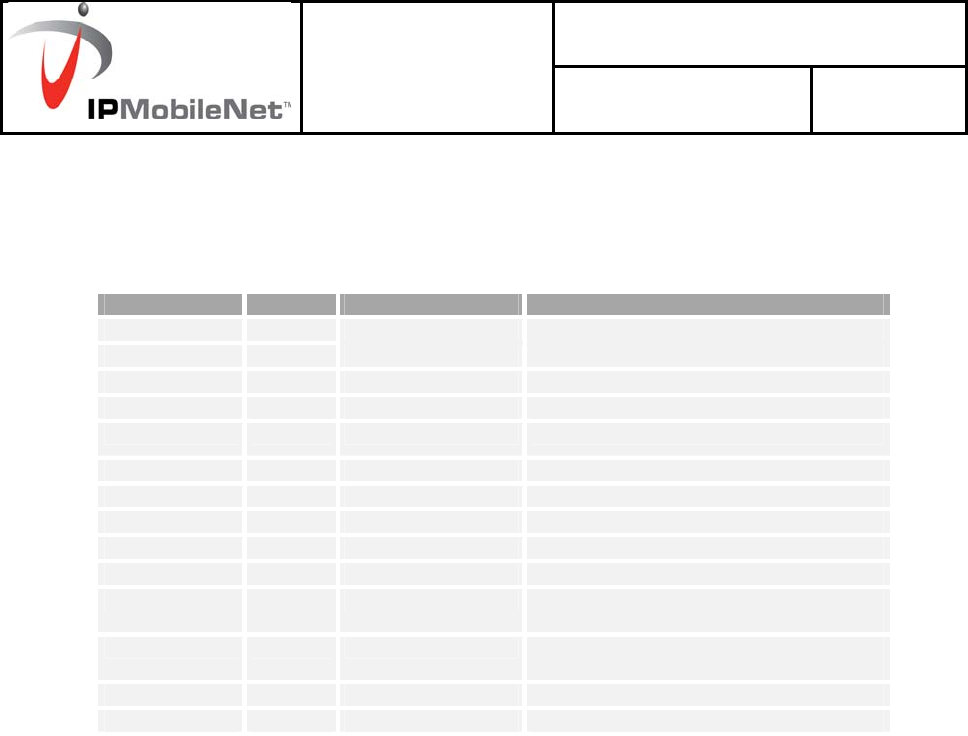
6. RCPU P25 (REPEATER CONTROL)
LEDs to indicate the module status.
LED TYPE NORMAL STATUS FUNCTIÓN
ON Green On Power supply correct
REF. ERROR Red Off Failure in the 10 MHz reference
INT. ERROR Red Off Internal failure
BBSR ERROR Red Off BSR bus failure
DIV ERROR Red Off Diversity failure
CNC ERROR Red Off Communication failure with the CNC
AUX Green Off Not used
MCCH Green Off / On Main carrier indicator
RX Green Flickering APCO P25 information received
TX Green On APCO P25 information transmission
ETH LINK1 Yellow On Link between the local network switch and
the RCPU P25 module in Ethernet port 1
ETH LINK2 Yellow Off Link between the local network switch and
the RCPU P25 module in Ethernet port 1
ETH RX Green Flashing Reception of an Ethernet packet
ETH TX Green Flashing Transmission of an Ethernet packet

Code: Installation Guide EZPRO25 RF.d
o
INSTALLATION
GUIDE Date: 12/18/2007 Page: 13 of 21
Initial Release
Revision: 00
5.4 CABLING AND CONNECTORS
♦ BSR75
8.- Power supply connector.
9.- Transmission power antenna connector.
10.- SMB RF cables.
11.- Reception antenna connector (receiver chain 1)
12.- Reception antenna connector (receiver chain 2)
13.- Reception antenna connectors for the RRX2 P25 option / antenna connectors for the
GPS, depending on the inserted module.
14.- Ethernet B connector.
15.- Ethernet A connector.
16.- SYNC IN2 connector.
17.- SYNC IN1 connector.
18.- SYNC OUT1 connector.
19.- SYNC OUT2 connector.
20.- Maintenance connector for BSR bus.
21.- Connector for VT100 for RCPU P25module maintenance.
22.- Connector for VT100 for RRX2 P25 module maintenance.
23.- Connector for VT100 for RRX1 P25 module maintenance.
24.- Connector for VT100 for RTX P25 module maintenance.
25.- TNC connector for 50Ω load.

Code: Installation Guide EZPRO25 RF.d
o
INSTALLATION
GUIDE Date: 12/18/2007 Page: 14 of 21
Initial Release
Revision: 00
6. INSTALLATION GUIDE
The following recommendations must be followed closely before starting up the EZPRO25 RF
module.
6.1 LOCATION
The EZPRO25 RF have been designed in the standard format of 19” / 3 units high, and so
they must be installed in cabinets with this format.
The EZPRO25 RF site must be permanent, well-ventilated and without vibrations.
6.2 POWER SUPPLY CONNECTION
DC power supply: check that the power supply source and/or the battery to be used meets the
voltage and current requirements necessary to supply the equipment:
Nominal voltage: 26.4VDC (range: from 21.6 to 28VDC)
Minimum source current: 10 A
There is a 15 A internal fuse in the RPS module (Ref. 1 of BSR) to protect the
equipment from over-voltage. There is a power control circuit in the RPS P25 module
in order to avoid an overcurrent condition.
If lead batteries are used, they are to be placed as far from the EZPRO25 RF as
possible to prevent corrosion in the repeater due to battery vapours. They should be
situated in a well-ventilated place.
Use the power supply connector provided (D013000) to connect the EZPRO25 RF to
the power supply source. Use a cable with 2.5 mm2 minimum diameter (or AWG-12).
Ensure that the connection is made with the correct polarity.
Ensure that the earth connection is made. Make this connection with a cable of
maximum diameter and minimum length.
NEVER use a gas or electricity conduit as an earth.

Code: Installation Guide EZPRO25 RF.d
o
INSTALLATION
GUIDE Date: 12/18/2007 Page: 15 of 21
Initial Release
Revision: 00
6.3 ANTENNA CONNECTION
Choose the most adaptable antenna for the installation. The antenna must have an
impedance of 50 ohms to the equipment transmission frequency. Install the antenna
in accordance with the manufacturer’s instructions.
Use a cable coaxial, avoiding as much as possible large cable lengths. Cable
impedance is 50 ohms.
Measure the ROE of the installation. Never accept a ROE greater than 2.
If a duplexer module or a band pass filter is required, adjust them to the work
frequency before starting up.
6.4 SWITCHING ON THE EZPRO25 RF
Check the connections between the modules.
Check that the power supply source is connected correctly.
Check that the RF SMB cables are connected correctly (see Rear View diagram Ref.
10).
Check the connections of the antennas in the RPA P25 and RRX modules.
Only in case of the EZPRO25 RF check the 50Ω load is connected to the rear TNC
connector in the RPA P25.
Check that the Ethernet connections to the CNC/Gateway are in accordance with the
configuration.
Check that the RPS P25 module LED SUPPLY is on.
Activate the power on switch on the RPS P25 module.
Check that the 24V LED and the 13.2V LED on the RPS P25 module or the 26.4V
LED and 13.2V LED on the RPS P25 module are on and check that the LEDS ON are
switched on for the other modules.
Wait for the EZPRO25 RF to start up.
Check that the mobile equipment is registered in the EZPRO25 RF.
Note: see section 5 for more information on references for the different modules and LEDs.
Code: Installation Guide EZPRO25 RF.d
o
INSTALLATION
GUIDE Date: 12/18/2007 Page: 16 of 21
Initial Release
Revision: 00
7. CONFIGURATION
A EZPRO25 RF is configured via an NMS (Network Management System). To configure the
EZPRO25 RF, consult the NMS manual.
8. INCIDENTS
The repeater must be repaired by authorized technical personnel only. If a EZPRO25
RF failure occurs, the entire EZPRO25 RF must be replaced. If transmitter module is
damaged and there is not an entire EZPRO25 RF available to replace, set RTX P25 and
RPA P25 modules previously calibrated jointly. In last case and if is not possible to carry out
one of the two previous options, replace one of these two modules and make the gain
calibration again.
If an error or alarm occurs in the EZPRO25 RF, this is indicated in the corresponding LED for
each one of the modules. The following list shows the possible failures and their solutions.
8.1 ALARMS
Led
indication Status Failure / Solution
SUPPLY OFF POWER SUPPLY FAILURE. CHECK THAT THE
SOURCE AND THE POWER SUPPLY CABLE
ARE CORRECTLY CONNECTED. CHECK THE
INTERNAL FUSE OF THE RPS P25. CONTACT
TECHNICAL SERVICES IF UNSOLVED.
24V or 26.4V OFF Power supply failure. Contact Technical services.
RPS P25
13.2V OFF Power supply failure. Contact Technical services.
RPA P25
ON OFF POWER SUPPLY FAILURE. CONTACT
TECHNICAL SERVICES.
!

Code: Installation Guide EZPRO25 RF.d
o
INSTALLATION
GUIDE Date: 12/18/2007 Page: 17 of 21
Initial Release
Revision: 00
TX POWER OFF No power transmission in the antenna. Wait for
EZPRO25 RF to be started up by the CNC. Check
other LED indications. Contact Technical Services if
unsolved.

Code: Installation Guide EZPRO25 RF.d
o
INSTALLATION
GUIDE Date: 12/18/2007 Page: 18 of 21
Initial Release
Revision: 00
ON OFF INTERNAL POWER SUPPLY FAILURE.
CONTACT TECHNICAL SERVICES.
REF. ERROR ON Failure in the 10MHz reference. Contact Technical
services.
INT. ERROR ON Internal failure. Contact Technical services.
BBSR
ERROR ON Communication failure with the RCPU P25 module.
Check that all the modules are correctly installed.
Contact Technical services if still unsolved.
RPA P25
ERROR ON FAILURE IN THE RPA P25 MODULES. CHECK
THAT THE RF SMB CABLES (REF. 10) ARE
CORRECTLY CONNECTED. CONTACT
TECHNICAL SERVICES I STILL UNSOLVED.
RTX P25
RPW ERROR ON Reflected power alarm. Check that the antenna is
correctly installed. Contact Technical services.
ON OFF INTERNAL POWER SUPPLY FAILURE.
CONTACT TECHNICAL SERVICES.
REF. ERROR ON Failure in the 10MHz reference. Contact Technical
services.
INT. ERROR ON Internal failure. Contact Technical services.
RRX P25
BBSR
ERROR ON Communication failure with the RCPU P25 module.
Check that all the modules are correctly installed.
Contact Technical Services if still unsolved.
ON OFF INTERNAL POWER SUPPLY FAILURE.
CONTACT TECHNICAL SERVICES.
REF. ERROR OFF Failure in the 10MHz reference. Contact Technical
services.
BSYNC P25
TIME GPS OFF IF GPS IS ACTIVATED, THERE IS FAILURE IN
THE DATA FRAME. CONTACT TECHNICAL
SERVICES.

Code: Installation Guide EZPRO25 RF.d
o
INSTALLATION
GUIDE Date: 12/18/2007 Page: 19 of 21
Initial Release
Revision: 00
PPS GPS OFF IF GPS IS ACTIVATED, THERE IS FAILURE IN
THE PPS SIGNAL OF THE GPS:
- CHECK THAT THE STARTING UP PERIOD
HAS BEEN EXCEEDED (ABOUT 10 MINUTES
AFTER SWITCHING ON)
- CHECK THE GPS ANTENNA CONNECTION.
- CHECK THE CORRECT POSITIONING OF THE
GPS ANTENNA, IN ACCORDANCE WITH THE
MANUFACTURER’S INSTRUCTIONS.
CONTACT TECHNICAL SERVICES IF STILL
UNSOLVED.
TIME LOCAL OFF IF GPS IS NOT ACTIVATED, THERE IS
FAILURE IN THE LOCAL REFERENCE DATA
FRAME. CONTACT TECHNICAL SERVICES.
PPS LOCAL OFF IF GPS IS NOT ACTIVATED, THERE IS
FAILURE IN THE LOCAL PPS SIGNAL.
CONTACT TECHNICAL SERVICES.

Code: Installation Guide EZPRO25 RF.d
o
INSTALLATION
GUIDE Date: 12/18/2007 Page: 20 of 21
Initial Release
Revision: 00
ON OFF INTERNAL POWER SUPPLY FAILURE.
CONTACT TECHNICAL SERVICES.
REF ERROR ON Failure in the 10MHz reference. Check that the BSYNC
P25 module is installed or that the SYNC IN cable is
correctly connected. Contact Technical services if still
unsolved.
INT ERROR ON Internal failure. Contact Technical Services.
BBSR
ERROR ON Communication failure by the EZPRO25 RF bus. Check
that all the modules are correctly installed. Contact
Technical services if still unsolved.
DIV ERROR ON Error in diversity: occurs when the difference in received
power between received paths exceeds a level (20 dBs
by default) for a consecutive number of receptions.
These receptions on the received paths which do not
have sufficient power are not counted.
This alarm does not disappear until there are no
receptions with the sufficient power, and until the
difference of received power between received paths
does not exceed the level previously mentioned.
Check diversity configuration in the CNC.
Check that the reception antennas are correctly
installed. Contact Technical services if still unsolved.
CNC ERROR ON Communication failure with the CNC. Check the
Ethernet connections.
Check that the CNC is working correctly. Contact
Technical Services if still unsolved.
RX Continuous
ON Interference detection.
Check the installation. Check that the work frequencies
are correct.
ETH LINK1 OFF Failure in Ethernet link 1.
Check Ethernet connection 1 and the Switch A.
ETH LINK2 OFF Failure in Ethernet link 2.
Check Ethernet connection 2 and the Switch B.
ETH RX OFF Packets are not received by Ethernet.
Check the Ethernet connections.
RCPU P25
ETH TX OFF Packets are not sent by Ethernet.
Check the Ethernet connections.

Code: Installation Guide EZPRO25 RF.d
o
INSTALLATION
GUIDE Date: 12/18/2007 Page: 21 of 21
Initial Release
Revision: 00
8.2 ALARMS WITHOUT STATUS LEDS
8.2.1 Interference at the bsr.
This alarm is monitored in APCO P25 Network Management System (NMS). See “APCO P25
Event List” in NMS help.
An interference in the EZPRO25 RF is activated when a high number of invalid consecutive
receptions occurs at a EZPRO25 RF. An invalid reception is that which has a signal level higher than
the minimum level of reception of the carrier, but it is not recognised as a APCO P25 signal.
This alarm is switched off upon correct reception.