IP Mobilenet IPB800 Base Station User Manual 369551
IP Mobilenet, LLC Base Station 369551
Contents
- 1. Owners Manual
- 2. Users Manual
Users Manual

I
IP
PS
Se
er
ri
ie
es
s
B
Ba
as
se
e
S
St
ta
at
ti
io
on
n
U
Us
se
er
r
M
Ma
an
nu
ua
al
l
Released: September 4, 2003
IPMN p/n: 516.80499.UM
Revision: A
16842 Von Karman Avenue, Suite 200 Irvine, CA 92606
Voice: (949) 417-4590 Fax: (949) 417-4591
www.ipmobilenetinc.com

2003 IPMobileNet, Inc. Revision & Copyright IPSeries BS User Manual / Rev. A / 04-September-03
DOCUMENT REVISION CONTROL
Document Title: IPSeries Base Station User Manual
New Release Version: A
New Release
Date
Previous
Version Action Old
Pages
New
Pages
09/04/03 -- Release Revision A N/A N/A
COPYRIGHTS STATEMENT
The IPSeries Base Station User Manual is copyrighted to IPMobileNet, Inc.
All rights reserved. This document is confidential and proprietary information of IPMobileNet, Inc. The
distribution or duplication of this document is expressly forbidden without IPMobileNet’s prior written consent.
Disclaimer. While reasonable efforts were made to ensure that the information in this document was complete and
accurate at the time of printing, IPMobileNet, Inc. can assume no responsibility for any inaccuracies. Changes and
corrections to the information within this document may be incorporated in future releases.

TABLE OF CONTENTS
2003 IPMobileNet, Inc. 3 IPSeries MR User Manual / Rev. A / 04-September-03
MANUAL COMPONENTS.........................................................................................................................4
Manual Purpose ...........................................................................................................................4
Manual Contents ...........................................................................................................................4
Manual Use ...................................................................................................................................5
Audience .......................................................................................................................................5
CHAPTER 1: INTRODUCTION................................................................................................................6
Product Description.......................................................................................................................6
Product Functionality.....................................................................................................................6
External Features..........................................................................................................................7
Product Specifications...................................................................................................................9
Theory of Operation ....................................................................................................................10
Block Diagram Definitions..............................................................................................10
CHAPTER 2: BASIC NETWORK CONFIGURATIONS.........................................................................12
Basic Network Connection..........................................................................................................12
Network Connection to an Existing LAN.....................................................................................13
CHAPTER 3: PRODUCT SETUP AND PRELIMINARY TESTING .......................................................14
Base Station Setup .....................................................................................................................14
Rack Unit Mounting........................................................................................................14
Preliminary Testing .....................................................................................................................15
Checklist for Required Material for Preliminary Testing.................................................15
Preliminary Testing Procedure....................................................................................................16
CHAPTER 4: PRODUCT INSTALLATION ............................................................................................17
Installation Overview ...................................................................................................................17
Adjusting the Power ....................................................................................................................18
Installation Instructions................................................................................................................21
Interconnection Diagram................................................................................................21
Base Station Installation into the Rack Unit...................................................................21
Single Base Station Configuration .................................................................................23
Multiple Base Station Configurations............................................................................. 23
Typical Antenna Configuration.......................................................................................24
Near-Field Exclusion Zone................................................................................25
Power Connection..........................................................................................................26
Post Installation Checklist ..............................................................................................27
CHAPTER 5: PROGRAMMING INSTRUCTIONS .................................................................................28
Overview .....................................................................................................................................28
HyperTerminal Setup ..................................................................................................................28
Factory Default Save and Restore..............................................................................................30
Additional Programming Needs ..................................................................................................30
CHAPTER 6: CUSTOMER SUPPORT ..................................................................................................31
Ordering Parts.............................................................................................................................31
Customer Support .......................................................................................................................31
Reporting Problems with the Documentation .............................................................................31
APPENDIX A: Backhaul Requirements................................................................................................32
APPENDIX B: Base Station IPMessage Parameters........................................................................... 34
FIGURE LISTING ....................................................................................................................................37
GLOSSARY .............................................................................................................................................38
INDEX ......................................................................................................................................................42

MANUAL COMPONENTS
2003 IPMobileNet, Inc. 4 IPSeries MR User Manual / Rev. A / 04-September-03
Manual Purpose
The purpose of the IPSeries Base Station User Manual is to provide IPMobileNet dealers and customers
with the necessary information required to install, operate, and troubleshoot problems with the IPSeries
base station.
Manual Contents
This user manual contains the following sections:
Chapter 1: Introduction
The Introduction provides a description of the base station as well as a general overview of its
functionality, product interfaces, and theory of operation with a block diagram and definitions.
Chapter 2: Basic Network Configurations
Basic Network Configurations provides a series of network diagrams depicting possible network
configurations.
Chapter 3: Product Setup and Preliminary Testing
Product Setup and Preliminary Testing provides a diagram and information required for mounting the
base station in a rack unit as well as preliminary testing prior to putting the base station into service.
Chapter 4: Product Installation
Product Installation provides diagrams and instructions for installing the base station and other
required components.
Chapter 5: Programming Instructions
Programming Instructions provides programming and setup instructions for setting up the base
station and its interfaces.
Chapter 6: Customer Support
Customer Support provides instructions for ordering parts, documentation support, and reporting
problems.
Appendix A: Backhaul Requirements
Appendix B: Base Station IPMessage Parameters
Figure Listing
Glossary
Index

MANUAL COMPONENTS
2003 IPMobileNet, Inc. 5 IPSeries MR User Manual / Rev. A / 04-September-03
Manual Use
Special icons appear throughout this manual to emphasize important information related to the chapter in
which the icons are found. The definitions for these icons are listed below.
1 It is imperative that the user read this section carefully prior to continuing to the next chapter of
this user manual.
TABLE 1: ICON HELPS
ICON INDICATES DEFINITION
NOTE This icon indicates that a note follows highlighting
or stressing a special point.
1 CAUTION
This icon indicates that a precautionary message
follows. Carefully read the message following this
icon and proceed with caution.
Audience
This user manual is intended for specific use by IPMobileNet, Inc. staff, dealers, and customers. This
user manual is not to be reproduced without expressed written consent of IPMobileNet Management.
CHAPTER 1: INTRODUCTION
2003 IPMobileNet, Inc. 6 IPSeries MR User Manual / Rev. A / 04-September-03
Product Description
The content of this manual applies to all frequency ranges of the IPSeries Base Stations, unless
otherwise specified. This manual will note key differences when appropriate.
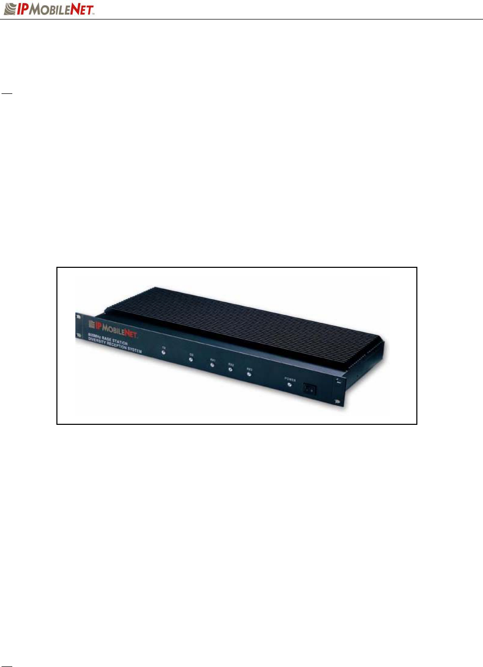
The IPSeries Base Stations are intelligent devices designed for the stringent requirements of mobile data
communication systems. Intended for mounting in rack units, the base station requires very little room at
tower sites and may be connected to via Serial Line Internet Protocol (SLIP) ports or Ethernet. The base
station circuit boards are built using surface mount technology (SMT) and through-hole components. At
the minimum, the unit requires a 13.8 VDC power supply, antenna system, and high-speed data
connection to an Internet Protocol Network Controller (IPNC) system to operate. The base station is
typically teamed up with a Power Amplifier (PA) and third-party system components such as antennas,
preamplifiers, preselectors, filters, and combiners.
Figure 1: IPSeries Base Station External Illustration (Front View)
Product Functionality
The base station utilizes an internal high-performance 4-level Frequency-Shift Keying (FSK) wireless data
modem (19200 bps) for 25 kHz channel spacing, a multi-layered approach to signaling reliability,
including patented multi-receiver Intelligent Diversity Reception, dynamic scrambling, data interleaving
for burst error protection, Forward Error Correction (FEC), and Viterbi soft-decision algorithms.
The IPSeries Base Station technology includes IPMobileNet’s Diversity Reception (DR) capability.
Diversity Reception reduces the number of fades and the effects of multi-path reception. With the use of
three (3) antennas, mounted as far apart as possible on the base station tower, the Diversity Reception
System (DRS) minimizes the effects of fading. One of the antennas is likely to receive a viable signal
while the others may not. DRS minimizes fading effects by comparing the signal levels from the three (3)
antennas, and selecting the strongest signal.
Diversity is most effective when the vehicle using an IPSeries Mobile Radio is in motion.
CHAPTER 1: INTRODUCTION
2003 IPMobileNet, Inc. 7 IPSeries MR User Manual / Rev. A / 04-September-03
External Features
The base station technology is enclosed in a sturdy aluminum case.
1 The product warranty becomes void if an uncertified or unauthorized individual removes the base
station cover.
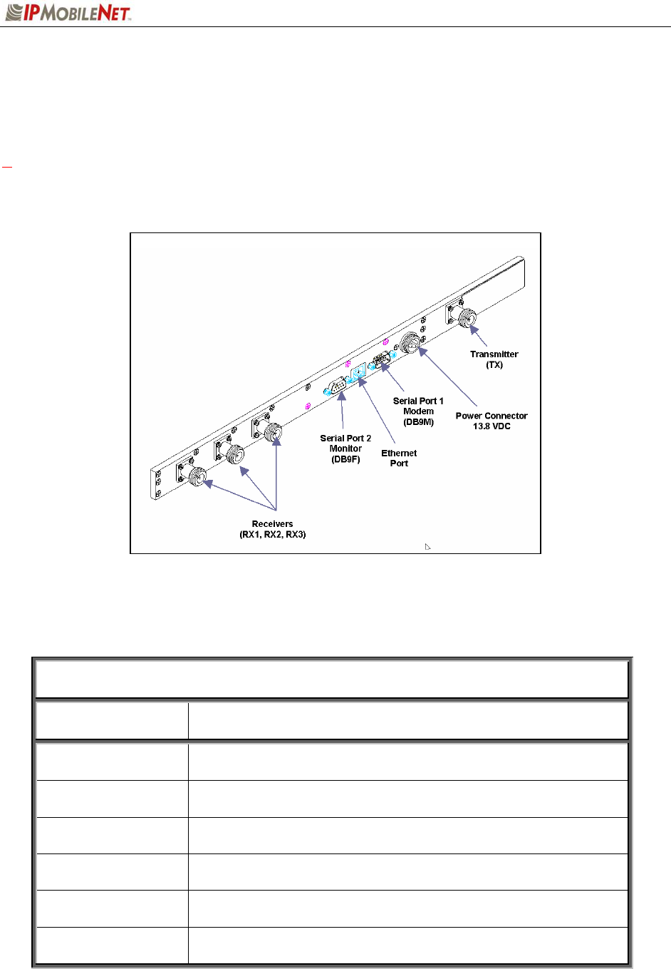
Figure 2: External Connectors of an IPSeries Base Station (Rear View)
The base station’s rear external connectors consist of the following components:
TABLE 2: EXTERNAL FEATURES (Rear)
FEATURE DESCRIPTION
TX Transmitter antenna connection
RX1/RX2/RX3 Receivers 1, 2, and 3 antenna connections
Power Connector 13.8 VDC base station power connector
Serial Port 1 (DB9M) RS232 Serial Line Internet Protocol (SLIP) interface port
Serial Port 2 (DB9F) ANSI/TTY Terminal Connection (used for programming)
(9600 bps, no parity, 8-databits, 1-stop bit)
Ethernet Port RJ45 Ethernet 10 Base T interface port
CHAPTER 1: INTRODUCTION
2003 IPMobileNet, Inc. 8 IPSeries MR User Manual / Rev. A / 04-September-03
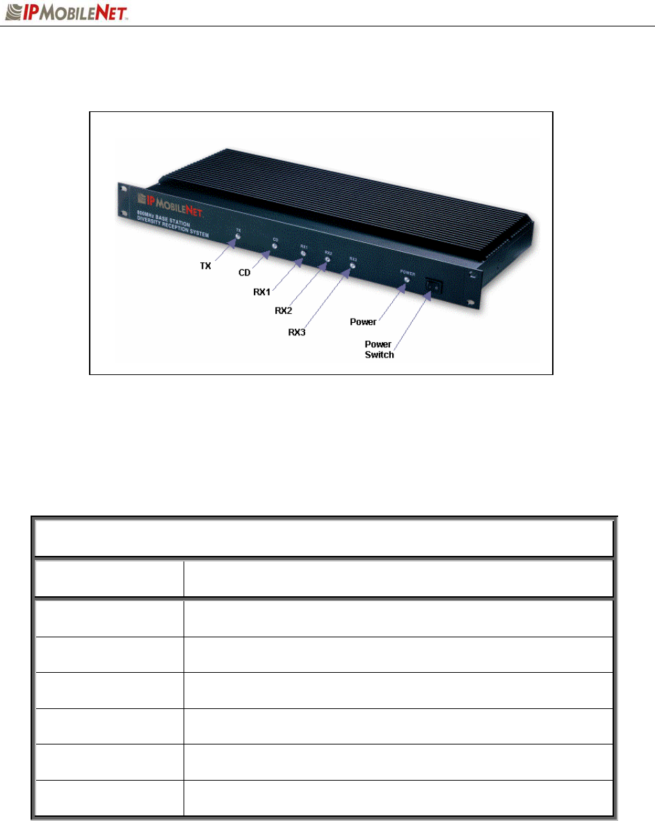
Figure 3: External Features of an IPSeries Base Station (Front View)
The base station’s front external features consist of six (6) LED (light emitting diodes) indicators defined
as follows:
TABLE 3: EXTERNAL FEATURES (Front)
LED Name When lit….
TX Indicates that transmission is in progress
CD Carrier detect indicates an RF message is detected
RX1 Indicates that receiving is progress on Receiver 1
RX2 Indicates that receiving is progress on Receiver 2
RX3 Indicates that receiving is progress on Receiver 3
POWER Indicates the base station is powered on

CHAPTER 1: INTRODUCTION
2003 IPMobileNet, Inc. 9 IPSeries MR User Manual / Rev. A / 04-September-03
Product Specifications
TABLE 4: PRODUCT SPECIFICATIONS
GENERAL SPECIFICATIONS
PARAMETER Specification IP100 Specification IP400 Specification IP800
frequency range 135 to 175 MHz 400 to 512 MHz 806 to 869 MHz
channel spacing / speed 12.5 kHz / 9600 bps
25.0 kHz / 19200 bps
12.5 kHz / 9600 bps
25.0 kHz / 19200 bps
12.5 kHz / 9600 bps
25.0 kHz / 19200 bps
mode of operation full-duplex, diversity reception full-duplex, diversity reception full-duplex, diversity reception
operating temperature range -30C to +60C (-22F to +140F) -30C to +60C (-22F to +140F) -30C to +60C (-22F to +140F)
power supply voltage 13.8 VDC +/-20% 13.8 VDC +/-20% 13.8 VDC +/-20%
power supply <1 amps receive <1 amps receive <1 amps receive
current consumption 16 amps transmit 13 amps transmit 8 amps transmit
number of channels 256 256 256
intelligent diversity reception triple receiver, diversity reception triple receiver, diversity reception triple receiver, diversity reception
antenna connections four (4) type N jacks
(tx, rx1, rx2, rx3)
four (4) type N jacks
(tx, rx1, rx2, rx3)
four (4) type N jacks
(tx, rx1, rx2, rx3)
interface connection RS232 serial port connector or
RJ45 Ethernet 10 Base T
RS232 serial port connector or
RJ45 Ethernet 10 Base T
RS232 serial port connector or
RJ45 Ethernet 10 Base T
dimensions (HxWxD / lbs) 1.75” X 19” X 8.2” / 9.5 lbs 1.75” X 19” X 8.2” / 9.5 lbs 1.75” X 19” X 8.2” / 9.5 lbs
regulatory FCC Part 90 and Part 15 FCC Part 90 and Part 15 FCC Part 90 and Part 15
IP TRANSMITTER SPECIFICATIONS
PARAMETER Specification IP100 Specification IP400 Specification IP800
frequency stability +/- 2.4 ppm @ operating temp +/- 1.5 ppm @ operating temp +/- 1.0 ppm @ operating temp
emission designator 20KF01D 20KF01D 20KF01D
spurious and harmonic -61 dBc max -59 dBc max -56 dBc max
transmit power 60 watts 40 watts 20 watts
transmit attack time less than 5 ms less than 5 ms less than 5 ms
IP RECEIVER SPECIFICATIONS
PARAMETER Specification IP100 Specification IP400 Specification IP800
sensitivity (voice) 12.0 dB SINAD@
-119 dB max level
12.0 dB SINAD@
-118dB max level
12.0 dB SINAD@
-118dB max level
distortion less than 3% @ 1.0 kHz less than 3% @ 1.0 kHz less than 3% @ 1.0 kHz
spurious response 85 dBm minimum 85 dBm minimum 85 dBm minimum
intermodulation distortion 75 dB minimum 75 dB minimum 75 dB minimum
CHAPTER 1: INTRODUCTION
2003 IPMobileNet, Inc. 10 IPSeries MR User Manual / Rev. A / 04-September-03
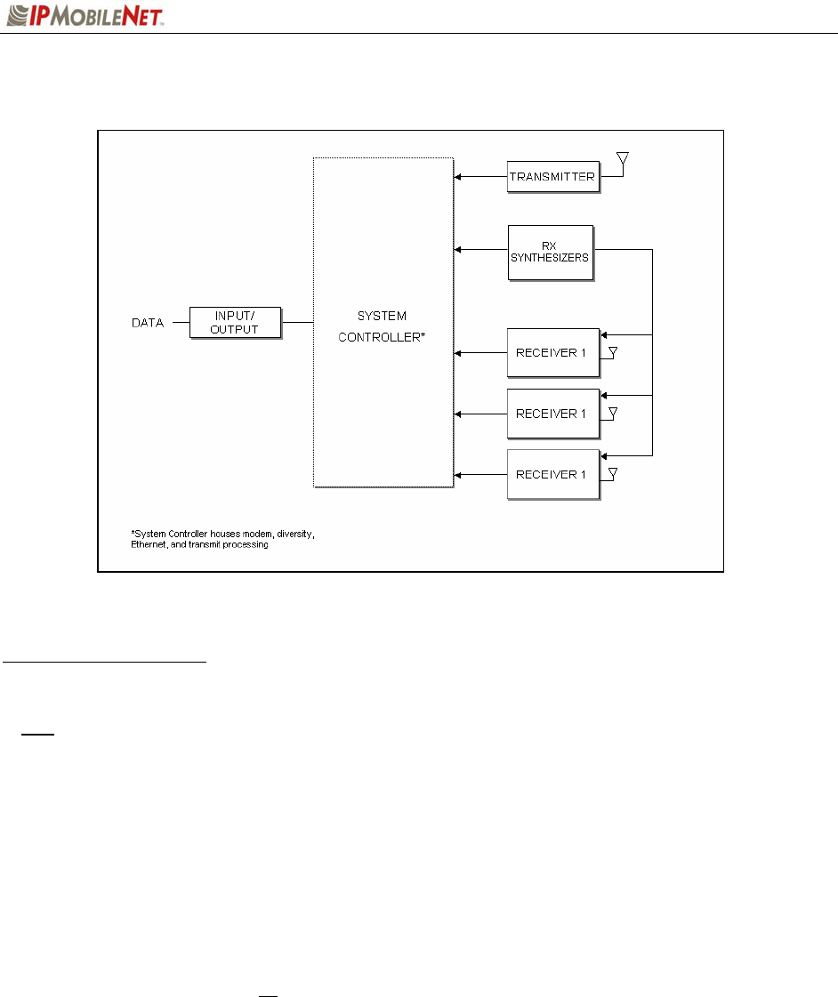
Theory of Operation
Figure 4: General Block Diagram
Block Diagram Definitions
For increased data security, the modem supports the U.S. Government developed Digital Encryption
Standard (DES) data encryption and decryption protocols. This capability requires installation of third-
party Internet Protocol (IP) compliant DES encryption and decryption software.
The standard IPSeries Base Station circuit board contains five (5) main sections defined below:
Input/Output Circuitry associated with one of the following base station’s data
connectors:
RS232 Serial Port DB9 Data Connector
RJ45 Ethernet 10 Base T Interface Connection
For further details on the Ethernet Controller refer to the Crystal
LAN Ethernet Controller Product Bulletin (CS8900A-
EthernetCtrlr.pdf) available on the Product Documentation CD.
System Controller Houses the modem, diversity, and Ethernet circuitry. Manages the
operation of the base station’s modem providing transmit timeout
protection in the event a fault causes the base station to become halted
in the transmit mode. The system controller also handles the loading of
selected transmit and receive frequencies into the injection synthesizer.
Includes memory for storage through Electrically Erasable
Programmable Read Only Memory (EEPROM) of the base station’s

CHAPTER 1: INTRODUCTION
2003 IPMobileNet, Inc. 11 IPSeries MR User Manual / Rev. A / 04-September-03
operating parameters, which are retained after the base station’s power
is cycled off.
Modems Convert data into an analog audio waveform for transmission and analog
audio from the receiver to serial data interface. There is one (1) modem
that is dedicated to the transmit operation and two (2) modems dedicated
to the receive operation. The modem dedicated to the transmit supports
a 115.2 KBPS data transmission rate on the serial port, SLIP protocol,
and a 19.2 KBPS OR 9.6 KBPS over-the-air data transmission rate.
Provides Forward Error Correction (FEC) and Error Detection (using
Cyclic Redundancy Check or CRC), bit interleaving for more robust data
communications, and third generation collision detection and correction
capabilities.
Diversity Reception Circuitry selects one of three (3) diversity receiver audio outputs for
processing by the modem by comparing the Received Signal Strength
Indication (RSSI) output from each receiver. Audio from the receiver
with the highest RSSI value is passed to the modems.
RX Injection The Injection Synthesizer board provides a highly stable local oscillator
signal for the three (3) receivers. This displays a serial data input/output
interface, synthesizer, and VCO.
Transmitter Consists of an exciter and a power amplifier module covering various
frequency bands in segments. The transmitter power control is included
with the power supply circuitry on the same board.
Receiver 1/Receiver 2/ Uses three (3) discrete receivers tuned to the same frequency.
Receiver 3 The three (3) receivers are required to support IPMobileNet’s base
station Diversity Reception System (DRS).
NOTE: Some installations use only two (2) receivers.
The receivers are double-conversion superhetrodynes with an
Intermediate Frequency (IF) of 45 MHz. Each receiver consists of
bandpass filters, RF amplifiers, a mixer, 45 MHz crystal filter, and a one-
chip IF system. The injection synthesizer provides the first local
oscillator signal and outputs from each receiver include RSSI and analog
audio for Diversity Reception.
Power Supply Power supply circuitry derives the various operating voltages required by
the base station. Fixed voltage regulators are employed through the
base station for this purpose.
CHAPTER 2: BASIC NETWORK CONFIGURATIONS
2003 IPMobileNet, Inc. 12 IPSeries MR User Manual / Rev. A / 04-September-03
Basic Network Configurations
This section provides basic network connection samples to help the user better understand some of the
possibilities in setting up their respective systems.
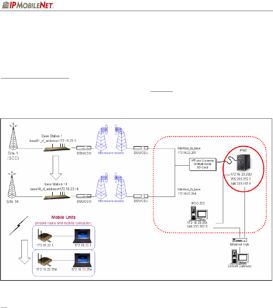
Basic Network Connection
Figure 5 depicts a basic network connection for a network inclusive of one (1) Internet Protocol Network
Controller (IPNC) and a range of base stations, mobile radios, mobile computers, and additional
components that can interface with the system.
Figure 5: Basic Network Connection
For serial connectivity to Ethernet only systems, please refer to the IPTurbo Converter Quick
Reference Guide (IPMN p/n: 516.80496.QR) on the Production Documentation CD (IPMN p/n:
480.0001.001).
CHAPTER 2: BASIC NETWORK CONFIGURATIONS
2003 IPMobileNet, Inc. 13 IPSeries MR User Manual / Rev. A / 04-September-03
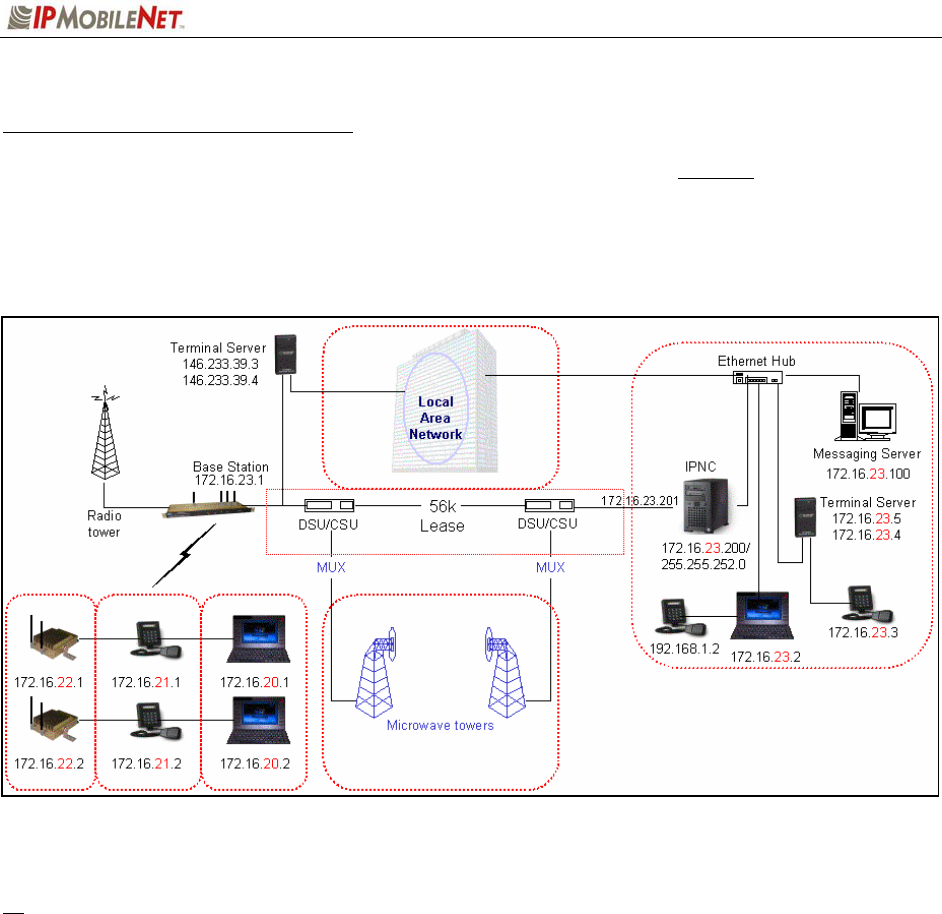
Network Connection to an Existing LAN
Figure 6 depicts network connection to an existing LAN (local area network) inclusive of one (1) IPNC,
one (1) base station, and a range of mobile radios, VIUs (voice interface units), mobile computers, and
additional components that can interface with the system. This diagram also shows a LAN VIU as well as
Terminal Server VIU.
Figure 6: Network Connection to an Existing LAN
For serial connectivity to Ethernet only systems, please refer to the IPTurbo Converter Quick
Reference Guide (IPMN p/n: 516.80496.QR) on the Production Documentation CD (IPMN p/n:
480.0001.001).
CHAPTER 3: PRODUCT SETUP AND PRELIMINARY TESTING
2003 IPMobileNet, Inc. 14 IPSeries MR User Manual / Rev. A / 04-September-03
Base Station Setup
Intended for rack unit configuration, the base station can be installed in an existing rack or assembled into
a rack of its own.
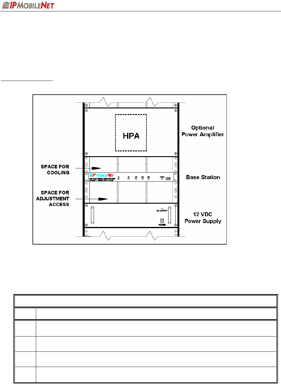
Rack Unit Mounting
Figure 7: Base Station Mounting in the Rack Unit (Front View)
Table 5 lists the required components for a base station setup.
TABLE 5: BASE STATION COMPONENTS REQUIRED FOR INSTALLATION
QTY DESCRIPTION
1 Frequency appropriate IPSeries Base Station
1 Ethernet cable
1 5’ DC power input cable with connector
4 RF coaxial cables (may require an additional cable if connecting the base station to a
power amplifier)

CHAPTER 3: PRODUCT SETUP AND PRELIMINARY TESTING
2003 IPMobileNet, Inc. 15 IPSeries MR User Manual / Rev. A / 04-September-03
Preliminary Testing
This section provides a functional preliminary test for the base station prior to installation. It is used to
determine the condition of the new base station before placing into service. If the base station is found to
be non-functional after completing this test, refer to Chapter 6: Customer Support for the appropriate
action.
This section applies to all base station frequency ranges.
Checklist for Required Material for Preliminary Testing
The following checklist provides a list of tools required to perform this preliminary test procedure.
TABLE 6: CHECKLIST OF REQUIRED EQUIPMENT FOR PRELIMINARY TESTING OF A BASE
STATION
1
Calibrated Base Station System – Consisting of the following components:
(1) IPSeries Base Station
(2) Desktop or laptop computer configured as an Internet Protocol Network
Controller (IPNC)
(3) Corresponding IPSeries Mobile Radio tuned to Base Station frequencies (If an
IPB138 base, use IP138 mobile)
(4) Desktop or laptop computer with two (2) available serial ports and Microsoft
Windows 98 or greater, IPMobileNet Dial-Up Networking, IPMessage software,
and HyperTerminal for base station installed
2 DC power supply with ammeter, with the appropriate volts, see page 9 Current Consumption
for each base station (Astron VS12M or equivalent)
3 Six (6) antennas (generic mag mounts) tuned to frequency or transceiver
4 Base Station power cable.
Serial Base Station Interface
No. Requirement 9
1 DB9 RS232 serial cable
2 IPTurboConverter (IPMN p/n: 900.00012.01)
3 IPTurboConverter Quick Reference Guide (IPMN p/n: 516.80496.QR)
Ethernet Base Stations Interface
No. Requirement 9
1 Ethernet RJ45 Cable
2 Ethernet Crossover Cable

CHAPTER 3: PRODUCT SETUP AND PRELIMINARY TESTING
2003 IPMobileNet, Inc. 16 IPSeries MR User Manual / Rev. A / 04-September-03
Preliminary Test Procedure
Perform the following initial setup to prepare the base station for preliminary test:
Step 1 Connect the base station to the 13.8 VDC power supply.
Step 2 Power on the base station and verify that the LED’s illuminate and the power LED on the
front panel remains illuminated.
Step 3 Verify that the base station DC-supply current is <1.2 amps.
Step 4 For the ideal serial or Ethernet setup please refer to the IPTurboConverter Quick
Reference Guide (IPMN p/n: 516.80496.QR) available on the Product Documentation CD
enclosed with this product.
Step 5 Connect the antennas to the mobile radio.
Step 6 Power on the mobile radio.
Step 7 Connect the antenna to the base station’s TX port.
Step 8 Recycle the base station power.
Step 9 Connect the antennas to the base station’s RX1.
Step 10 Verify that the RX1 and CD LED’s is illuminated when the mobile is attempting to
connect. Repeat Steps 9 and 10 with RX2 and RX3.
Step 11 From the Mobile PC, open the DOS prompt, then ping the IPNC with the following
command:
ping 172.16.23.200 (or replace with appropriate IPNC IP address).
Press [ENTER] and verify that the IPNC responds to the ping request. Also verify that
the base station carrier detect (CD) LED is lit followed by the TX LED.

CHAPTER 4: PRODUCT INSTALLATION
2003 IPMobileNet, Inc. 17 IPSeries MR User Manual / Rev. A / 04-September-03
Installation Overview
This chapter provides the basic setup involved in the installation process of an IPSeries Base Station.
For backhaul requirements, refer to Appendix A of this document.
1 Standard considerations such as air flow clearance above the base station for heat dissipation
and ensuring adequate space exists behind the base station for the routing of cables are of
primary importance.
A minimum clearance of 1 rack space is recommended for natural convection cooling.
Adjustment points are available through holes in the base station bottom cover. Sufficient space
below the base station should exist to facilitate adjustments.
Coax, power, and interface cabling service lengths with neat routing will make the removal and
replacement of the base station easier for functional testing and maintenance purposes.
To prevent injury and damage to the base station, exercise extreme caution throughout the
installation process and follow the reminders listed below.
Follow safety precautions for handling rack unit installations.
Do not alter the components listed in the Installation Requirements section, unless
substituions are noted within this chapter.
CHAPTER 4: PRODUCT INSTALLATION
2003 IPMobileNet, Inc. 18 IPSeries MR User Manual / Rev. A / 04-September-03
Adjusting the Power
The power output of the base station will depend upon whether it will be used to drive an external power
amplifier or transmit directly over-the-air.
In either case it is important to measure and set the transmitter power output using a wattmeter
and dummy load before connecting it to the power amplifier or antenna system.
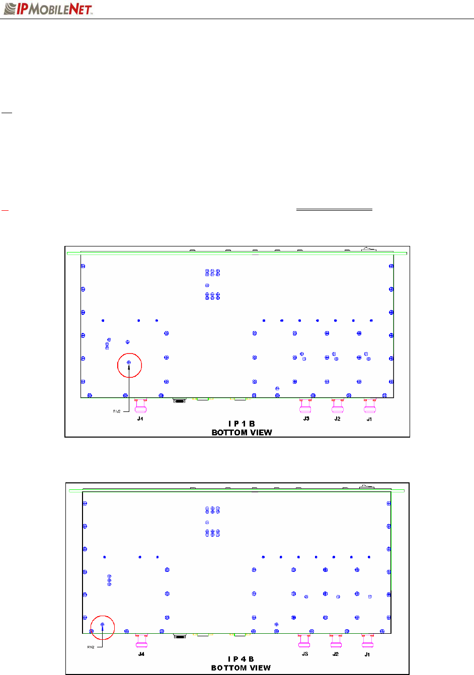
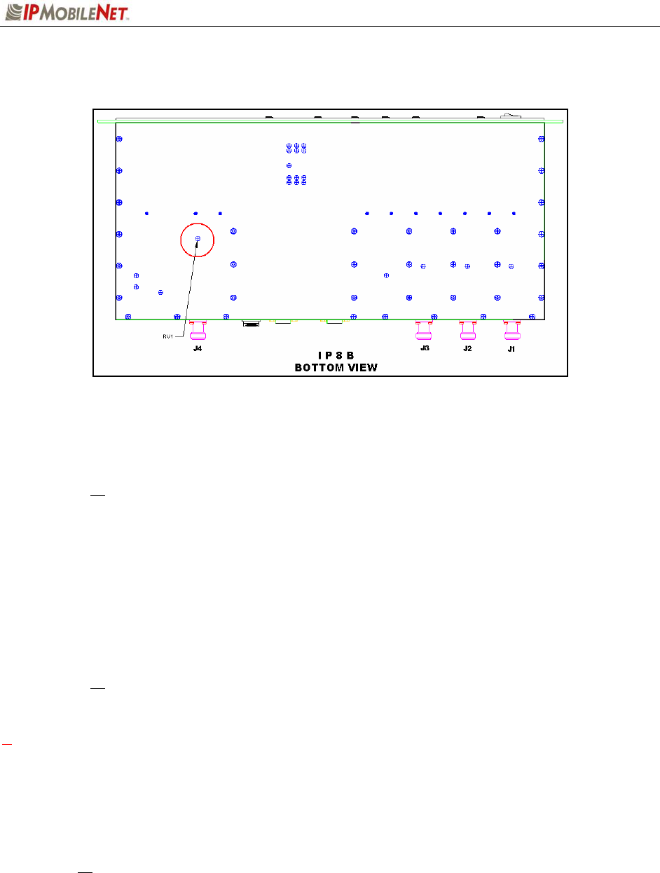
The base station power is adjusted mechanically by tuning a potentiometer (pot) on the bottom of the
base station. Depending upon the model, this pot can be reached through an access hole in the bottom
cover on either the exciter board or power amplifier board. Figures 8, 9, and 10 display the Power
Adjustment Potentiometer location for the IP1B, IP4B, and the IP8B.
1 Do not use a metal tool to make this adjustment, only use non-conducting alignment tools.
Equipment will be damaged if this warning is ignored.
Figure 8: Power Adjustment Potentiometer Location for the IP1B
Figure 9: Power Adjustment Potentiometer Location for the IP4B
CHAPTER 4: PRODUCT INSTALLATION
2003 IPMobileNet, Inc. 19 IPSeries MR User Manual / Rev. A / 04-September-03
Figure 10: Power Adjustment Potentiometer Location for the IP8B
Step 1 Connect a computer with the HyperTerminal utility to the base station’s monitor serial port.
Refer to the section titled HyperTerminal Setup located in Chapter 5: Programming
Instructions for HyperTerminal Setup and access instructions.
Step 2 Launch the HyperTerminal utility.
Step 3 Locate the adjustment hole (see Figures 8, 9, or 10 according to the model being used).
Step 4 Fit the tool to the potentiometer.
Step 5 Key the transmitter on the base station by typing X=1450,10 in the HyperTerminal window.
The base station will generate 10 data packets, each 1450 bytes in length.
If this does not work, check the base station’s MTU parameter. The X=number must
be smaller than the MTU value.
1 To avoid damage to the amplifier, when setting the power to drive an external amplifier, set the
base station power below the external amplifier’s maximum drive limit.
Step 6 If setting the power to drive an external amplifier, use a wattmeter and dummy load to
measure the output power of the base and set it to the amount of drive power that is will be
needed for the amplifier.
Be aware that the coaxial cable that will connect the base station to the power
amplifier may have completely different characteristics to the test cable used to
measure power output. If possible, adjust the power with the coaxial cable that will
be used in the system ensuring the power measured is exactly what will be fed into
the amplifier.

CHAPTER 4: PRODUCT INSTALLATION
2003 IPMobileNet, Inc. 20 IPSeries MR User Manual / Rev. A / 04-September-03
Step 7 Once the adjustment is made, connect the base station to the external amplifier and connect
the wattmeter and dummy load to the amplifier’s output.
Step 8 Measure the power output of the amplifier.
If the amplifier does not produce the expected power, additional adjustments to the
base station output are necessary. When making large adjustments in power, the
external amplifier should be disconnected from the base station and the base
station’s power reset.
1 Do not attempt to make large adjustments to the output power while the base is connected to the
external amplifier or if the external amplifier is not producing any power. The base station power
adjustment is very sensitive and it is possible to overdrive an external amplifier and ruin it with
just small movements of the power adjustment potentiometer. You must be sure to keep the
base station’s output power below the input drive limit of the external amplifier.
Step 9 Once the base station power is adjusted, reconnect the base station and the wattmeter to the
external amplifier and measure the output power of the external amplifier again using the
X=1450,10 command.
Step 10 Once the power amplifier is nearly at the proper output, small adjustments can be made to
the power output, while the base station is connected. Turning the power adjustment very
carefully while transmitting into the external power amplifier will enable the power to be
adjusted to exactly the right level.
1 Be careful not to apply sideways pressure to the adjustment potentiometer, otherwise the circuit
can be damaged. Always use a light touch when adjusting base station output power.
CHAPTER 4: PRODUCT INSTALLATION
2003 IPMobileNet, Inc. 21 IPSeries MR User Manual / Rev. A / 04-September-03
Installation Instructions
If setting up a new rack unit, make sure to complete the rack unit setup according to the
Manufacturers instructions.
Interconnection Diagram
Figure 11: Interconnection Diagram
Base Station Installation into the Rack Unit
Receiver and Transmitter Connections
To connect the base station, perform the following steps:
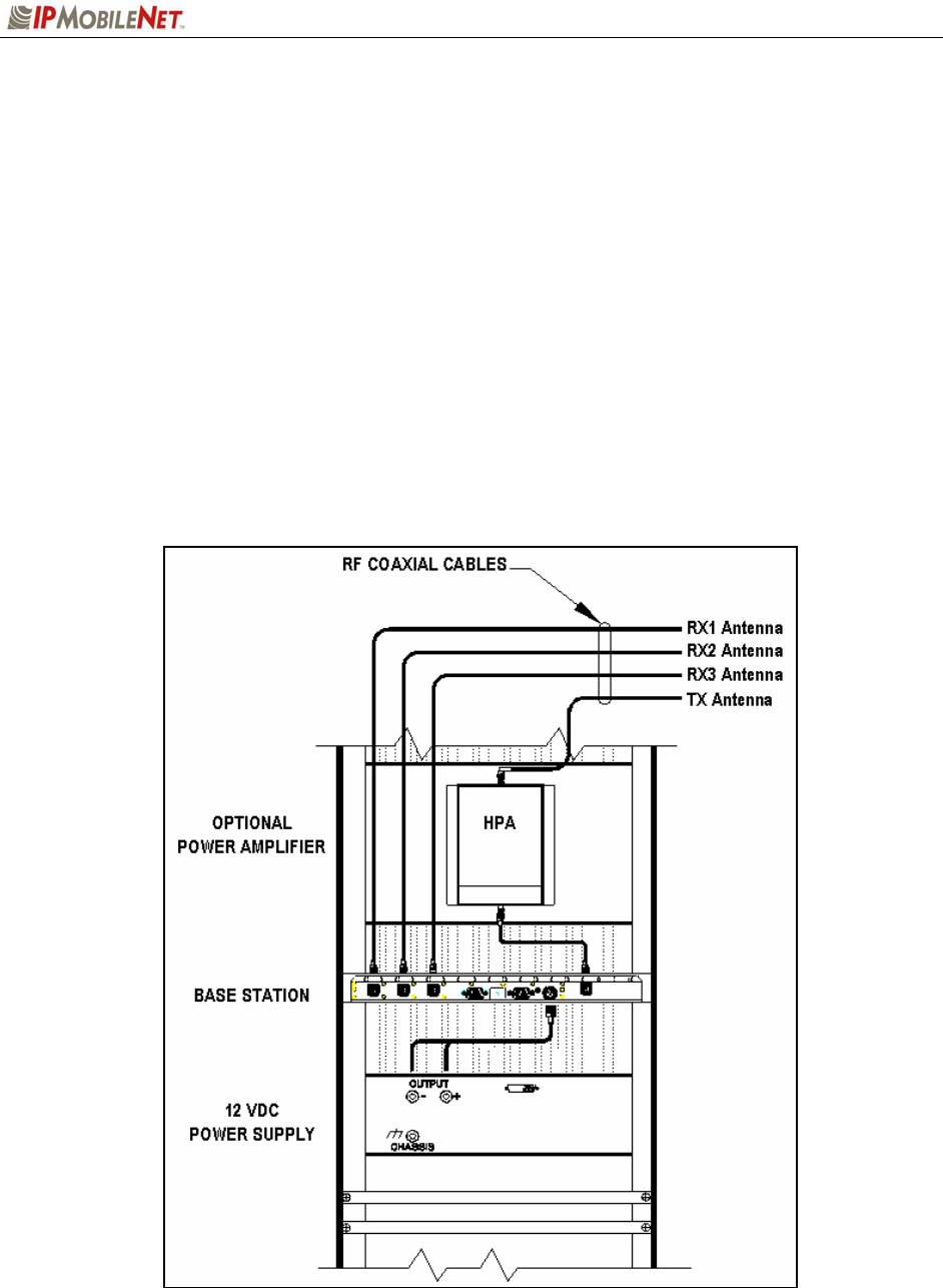
Step 1 Connect the RF coaxial cable to Receiver 1 (RX1) on the back of the base station.
Step 2 Route the cable neatly toward the top of the rack. Allow a little slack in the cable to avoid
accidental disconnection.
Step 3 Connect the RF coaxial cable to Receiver 2 (RX2) on the back of the base station.
Step 4 Route the cable neatly toward the top of the rack. Allow a little slack in the cable to avoid
accidental disconnection.
Step 5 Connect the RF coaxial cable to Receiver 3 (RX3) on the back of the base station.
Step 6 Route the cable neatly toward the top of the rack. Allow a little slack in the cable to avoid
accidental disconnection.
For clear identification for troubleshooting and/or maintenance activities, avoid crossing the
coaxial cables.
CHAPTER 4: PRODUCT INSTALLATION
2003 IPMobileNet, Inc. 22 IPSeries MR User Manual / Rev. A / 04-September-03
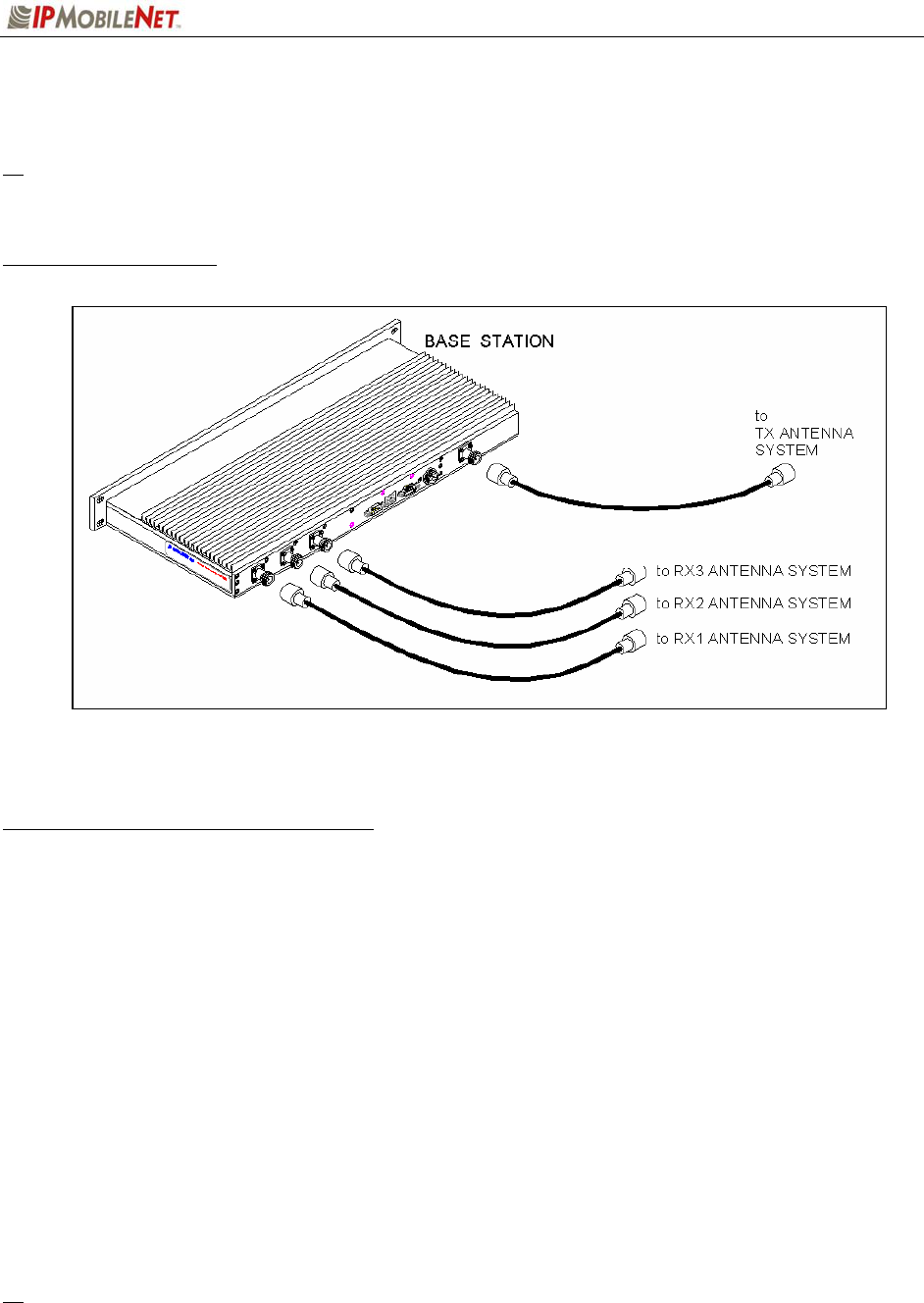
Step 7 Connect the RF coaxial cable to the Transmitter (TX) connection on the back of the base
station.
Step 8 If connecting to a power amplifier (as shown in the figure below), connect the cable from the
base station to the power amplifier via the Transmitter (TX) connection.
If not connecting to a power amplifier, skip to Step 11.
Step 10 If a power amplifier is used, connect an RF coaxial cable to the output port of the power
amplifier.
Step 11 Route the cable neatly toward the top of the rack. Allow a little slack in the cable to avoid
accidental disconnection.
Step 12 To perform the RX1, RX2, RX3, and TX antenna connections, refer to the Typical Antenna
Configuration section in this chapter.
Figure 12: Base Station Mounting and Connection in the Rack Unit (Rear View)
CHAPTER 4: PRODUCT INSTALLATION
2003 IPMobileNet, Inc. 23 IPSeries MR User Manual / Rev. A / 04-September-03
Single Base Station Configuration
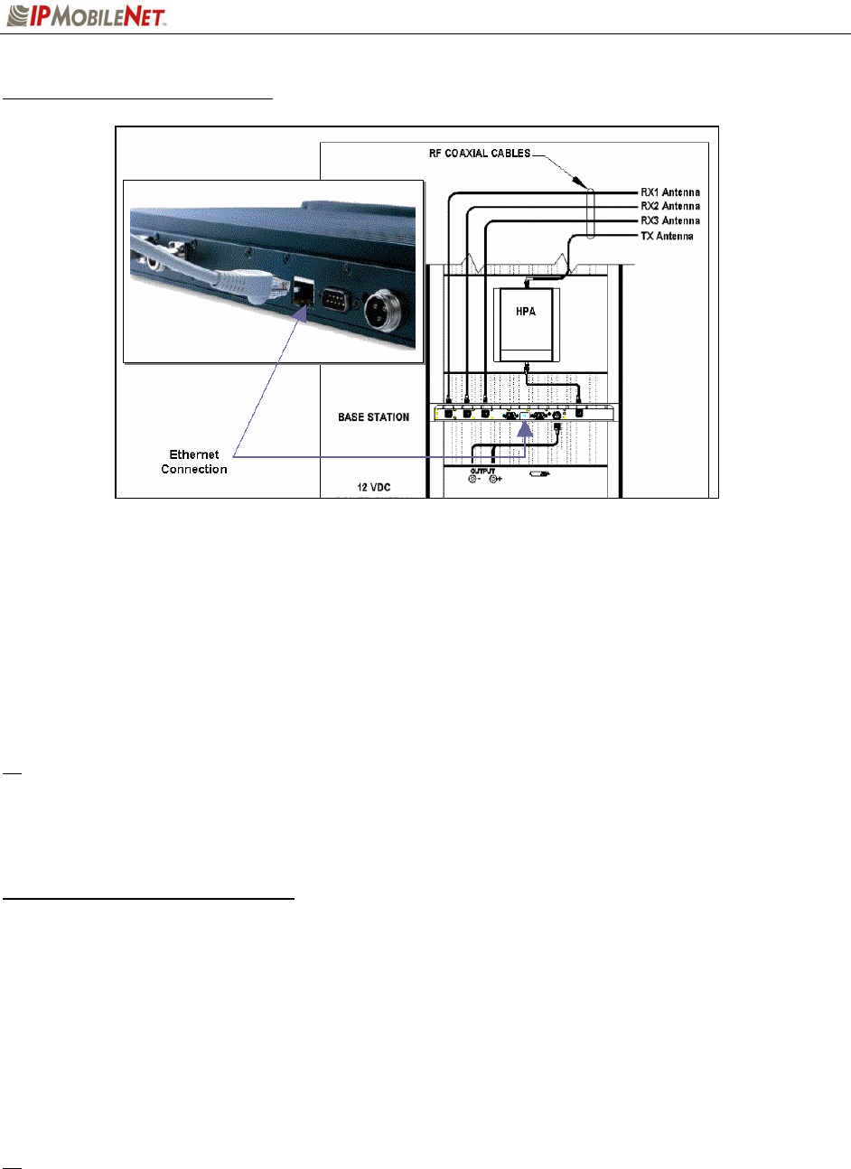
Figure 13: Base Station Ethernet Connection
To connect a single base station, perform the following steps:
Step 1 Plug in the Ethernet crossover cable into the Ethernet port on the base station (as shown in
the figure above).
Step 2 Route and plug in the Ethernet crossover cable to an IPMobileNet’s Internet Protocol Network
Controller (IPNC) via the hardware as defined by the organization’s configuration (see
Chapter 2 Basic Configuration Samples).
If connecting to a serial backhaul, an IPMobileNet IPTurbo Converter is required. If not
already ordered, please refer to Chapter 6 for ordering information. For connection
instructions, refer to 516.80496.QR IPTurbo Converter Quick Reference Guide (IPMN p/n:
516.80496.QR) available on the Product Documentation CD provided with this product.
Multiple Base Station Configurations
To connect multiple base stations, perform the following steps:
Step 1 Plug in the Ethernet cables to the back of each base station (as shown in the figure above)
and route according to selected setup (see Chapter 2 Basic Configuration Sample on page
12 and also refer to the 516.80496.QR IPTurbo Converter Quick Reference Guide for setup
instructions and scenarios).
Step 2 Route and plug in the Ethernet cables to an IPMobileNet’s Internet Protocol Network
Controller (IPNC) via the hardware as defined by the organization’s configuration (see
Chapter 2 Basic Configuration Samples).
If connecting to a serial backhaul, an IPMobileNet IPTurbo Converter is required. Refer to
Chapter 6 for ordering information. For connection instructions, refer to 516.80496.QR
IPTurbo Converter Quick Reference Guide.
CHAPTER 4: PRODUCT INSTALLATION
2003 IPMobileNet, Inc. 24 IPSeries MR User Manual / Rev. A / 04-September-03
Typical Antenna Configuration
Base station antenna configurations may vary from site to site depending on the type of mounting
structure, the presence of existing antennas, mounting structure loading limitations, etc. The following
information is provided as a guideline for a typical scenario.
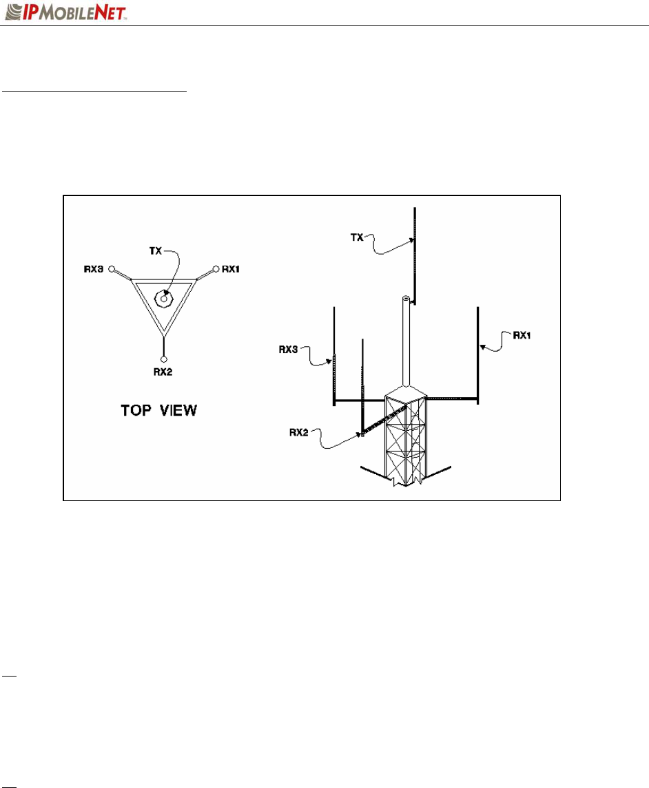
Figure 14: Typical Antenna Configuration
An otpimal antenna mounting configuration is shown in the figure above. The transmit antenna and
receive antennas are located at different elevations. This vertical separation provides the greatest degree
of isolation between transmit and receive antennas. The three (3) receive antennas are mounted at the
same elevation and are oriented in a 120 degree triangular pattern. A triangular orientation of the receive
antennas provides optimal diversity performance in an omnidirectional pattern.
The greater the separation between receive antennas, the greater the diversity gain; therefore,
the distance between antennas should be made as great as is practical.
In the event only two (2) receive antennas are used (i.e. a dual receiver diversity reception system), the
receive antennas should be mounted in a broadside orientation with respect to the radio coverage area.
To prevent the antenna’s radiation pattern from becoming distorted, the immediate area
surrounding each antenna should be kept free from conductive objects (i.e. other antennas, guy
wires, or the tower structure itself). The amount of clear area required to prevent pattern distorion
is equal to the antenna’s near-field exclusion.

CHAPTER 4: PRODUCT INSTALLATION
2003 IPMobileNet, Inc. 25 IPSeries MR User Manual / Rev. A / 04-September-03
Near-Field Exclusion Zone
The near-field exclusion zone (NFEZ) is the required distance between antennas to any other surfaces to
improve transmit and receive performance. The large radio frequency field that builts up around the
antenna upon transmitting is essential for proper data transmission. It can be severely corrupted by metal
objects in the NFEZ. As seen in the previous figure, the transmitting antenna is placed at the very top of
the tower especially if the base station will be required to transmit in all directions (omni-directional).
If the transmitting antenna cannot be positioned on the top of the tower and must be placed
on a tower arm, then it is important to realize that coverage will be shaded in the area behind
the tower from the anetnna. The installer must be certain that the area of desired coverage is
away from the tower and not behind it.
Receiving and transmitting antennas should not be on the same plane, especially VHF and
UHF systems where the frequency splits are relatiely small. An antenna in the near-field
exclusion zone that is tuned for the same frequency as the transmitting antenna will reradiate
the signal and create unwanted effects on the transmittal signal. The receivers will be
inundated by high levels of radio frequency energy from the transmitting antenna. This is
why it is important to include vertical separation in the plan for the base station installation.
The isolation provided by 30 feet of vertical spearation can dramatically improve the
performance of the base station.
An antenna’s NFEZ can be calculated as follows:
D = 2d2
λ
Where: D is the distance to the anenna’s near field boundary
d is the antenna’s longest linear dimension (in the same units as D)
λ is the wavelength (in the same units as D)
Maximizing the distance between the receive antennas will provide maximum diversity gain and
will minimize antenna radiation pattern distortion.
CHAPTER 4: PRODUCT INSTALLATION
2003 IPMobileNet, Inc. 26 IPSeries MR User Manual / Rev. A / 04-September-03
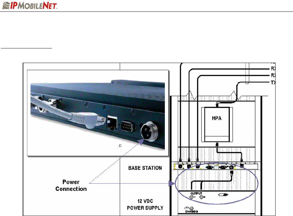
Power Connection
Figure 15: Base Station Power Connection
To connect the base station power connector, perform the following steps:
Step 1 Connect the power cable to the base station power supply connection (as shown in the figure
above).
Step 2 Connect the wires to the appropriate output (+ and -) output posts on the power supply (as
shown in the figure above).

CHAPTER 4: PRODUCT INSTALLATION
2003 IPMobileNet, Inc. 27 IPSeries MR User Manual / Rev. A / 04-September-03
Post Installation Checklist
Table 7 lists the tasks that should be performed upon completing installation.
TABLE 7: POST INSTALLATION CHECKLIST
NO. CHECKLIST ITEM ;
1 Scope out the entire area setup to locate any obvious problem areas.
2 Check antenna routing for safety concerns and near-field boundary setup.
3 Use tie wraps, where possible to ensure that all cables routed in parallel are
bundled together.
4 Perform appropriate testing to ensure base station works properly.
Once installation is complete make sure the area is clear of debris that would prevent proper
airflow and ventilation.
CHAPTER 5: PROGRAMMING INSTRUCTIONS
2003 IPMobileNet, Inc. 28 IPSeries MR User Manual / Rev. A / 04-September-03
Overview
This section applies to all frequency ranges of the IPSeries Base Stations. Important! The base
station’s IP address must be known prior to performing the procedures in this section.
The programming procedure should be performed when it is necessary to upgrade a base station’s
Firmware or to change the operating parameters to suit the customer’s needs before putting into
complete operation.
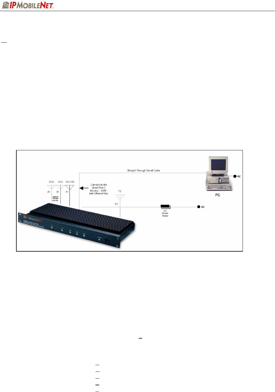
HyperTerminal Setup
To communicate and access parameters from the base station, the base station must be connected to a
HyperTerminal session setup on a personal computer.
Perform the following steps to setup the base station for communication with HyperTerminal:
Step 1 Connect the base station as shown in the figure below.
Figure #16: Base Station-to-HyperTerminal Connection Diagram
Step 2 Power on the personal computer.
Step 3 Power on the base station using the front panel power switch.
Step 4 On the personal computer’s desktop, click on the Start button and select Accessories,
Communications, and HyperTerminal.
Step 5 At the Connection Description window enter IPMNBS and click on the OK button.
Step 6 At the Connect To window, under Connect using: select COM1 or COM2 (whichever is
available on the computer) and click on the OK button.
Step 7 At the COM Properties window make sure the properties selected are as follows:
B
its per second: 9600
D
ata bits: 8
Parity: None
S
top bits: 1
F
low control: None

CHAPTER 5: PROGRAMMING INSTRUCTIONS
2003 IPMobileNet, Inc. 29 IPSeries MR User Manual / Rev. A / 04-September-03
Step 8 Click on the OK button.
Step 9 Open HyperTerminal.
Step 10 Recycle the base power and HyperTerminal displays the base’s Firmware revision.
Step 11 Type in a ? in the HyperTerminal screen and press [ENTER]. This will list the Base
Station parameters. If the cursor is not responsive, check the cables for proper
connection.
See Appendix A for Base Station Parameter definitions and default settings.
Ensure that the calibrated base station and the mobile radio antennas are
separated by at least 10 feet. If the antennas are too close, the mobile radio
receivers may overload by the transmitters resulting in intermittent
communication and high data errors.
Host serial = 115200,N,8,1, timeout=200
IPNC = 207.88.179.158, 207.88.179.157, 207.88.179.156, 207.88.179.152, 207.88.179.140
RF IP Address = 172.16.23.14
Tunnel Address = 8.4.2.14, Netmask = 255.255.255.240
Host interface = SLIP, no split frames, with status messages
tunnel = 1
Injection = LOW SIDE, 45MHz
pll type = MC145193
channel spacing = 12500
Reference frequency = 10.000 mHz
Channel Tx freq Rx freq Inj freq
Frequency=1 , 866.000000, 821.000000, 776.000000
Channel = 1
Serial number: 1234
TX quiet time = 5
Symbol sync time = 12 milliseconds, 0 extra inter-split-frame count
TX tail time = 5
Radio data rate = 19200
Max data tx time = 60 seconds
Carrier detect delay time = 8 milliseconds
Station ID = abcd
Station ID time = 0 minutes
Polarity = TX-, RX+
allow crc errors = 0
Allow base to base = 0
RSSI step = 25 (=18dBm)
default gateway = 0.0.0.0
Ethernet address = 00:00:00:00:00:00
Base station number = 14
SNTP interval = 16 seconds
num timeslots = 16
timeslot period = 992ms
timeslots per voice packet = 4
noise = -108dBm
DHCP Relay Agent = enable
-120dBm = (0)
-110dBm = (0)
-100dBm = (0)
-90dBm = (0)
-80dBm = (0)
-70dBm = (0)
-60dBm = (0)
-50dBm = (0)
-40dBm = (0)
-30dBm = (0)
Modem FEC = on
RX in progress message = 1
MTU = 1480
Signal Strength = DBM
IPNC query period = 10 secs

CHAPTER 5: PROGRAMMING INSTRUCTIONS
2003 IPMobileNet, Inc. 30 IPSeries MR User Manual / Rev. A / 04-September-03
Factory Default Save and Restore
For instructions on Factory Default Save and Restore Commands, please contact the Customer Service
number provided in Chapter 6 of this document.
Additional Programming Needs
Refer to the following technical notes and programming instructions and select the appropriate document
for additional programming needs.
TABLE #_: ADDITIONAL PROGRAMMING DOCUMENTS
TN01-011
Base Station Setup for Programming using an F167 Processor
This technical note provides instructions for establishing a connection that
allows programming of a Base Station using an F167 processor.
TN01-0012
Base Station Setup for Programming using an F168 Processor
This technical note provides instructions for establishing a connection that
allows programming of a Base Station using an F168 processor.
TN01-0020
Remote Firmware Updates for the IPNC and Base Station
This technical note provides instructions on how to perform remote Firmware
updates for the IPNetwork Controller and IPSeries base stations.
TS.0004-PI
Black Box Terminal Server
This programming instruction provides instructions on how to configure terminal
server Firmware when used to interface with a base station.

CHAPTER 6: CUSTOMER SUPPORT
2003 IPMobileNet, Inc. 31 IPSeries MR User Manual / Rev. A / 04-September-03
Ordering Parts
Replacement parts may be ordered from the following address:
Attn: Small Parts Sales
IPMobileNet, Inc.
16842 Von Karman Avenue, Suite 200
Irvine, CA 92606
Voice: (949) 417-4590
Fax: (949) 417-4591
Customer Support
To obtain assistance in troubleshooting problems with a product, please contact IPMobileNet’s Customer
Service Staff at (800) 348-1477.
Reporting Problems with the Documentation
To report problems or question concerning the documentation included in the shipment, please send an
e-mail to mlopez@ipmobilenetinc.com explaining the problem and the Publications Department will
respond as soon as possible.
Please ensure to include the following information with the e-mail message:
Your company name
Your name or other contact name
Return e-mail address
Manual name
Manual part number
Page number(s)
Description of the problem

APPENDIX A: BACKHAUL REQUIREMENTS
2003 IPMobileNet, Inc. 32 IPSeries MR User Manual / Rev. A / 04-September-03
Backhaul Systems
Considering the backhaul system between the base station location and the Internet Protocol Network
Controller location is one of the most critical elements of data transmission. Once data has been
received at the base station, it must be relayed to the IPNC at the user's location quickly, accurately, and
reliably. Industry standard backhauls are appropriate for IPMobileNet data transmission as long as data
is transmitted cleanly and dependably. Depending upon conditions and accessibility, the preferred
method of data transmission to the remote site is through wire.
Wired Backhaul
The Ethernet backhaul is preferred as it uses a T1 (or fractional T1) line or equivalent, which handles
larger volumes of digital data. If the backhaul will be via SLIP connection, then four wire DDS telephone
line capable of 56Kbps is recommended.
Do not order a 64Kbps line as it is incompatible with IPMobileNet’s equipment data transmission
speed.
One disadvantage of using wired lines is that the system is under the control of an outside
agency and telephone line faults or system outages impose potential loss of radio communication
through the site affected.
Microwave Transmission Link
Using a microwave transmission link is another option, which is often used when wire cannot be brought
into remote locations. Data transmission is generally very reliable, but adverse conditions can degrade
the quality of the data. High winds, ice on the microwave dish, and other environmental variables can
cause problems and prevent data or voice from completing transmitting.
Newest Backhaul
The 802.11 range of products for wireless data transmission. Several models of 802.11 have been used
successfully.
Be aware of the possibility of interference on the 2.4 GHz frequency range. The 802.11 product
should only be used for short hops with clear line-of-sight in an environment where minimal radio
interference will exist.

APPENDIX A: BACKHAUL REQUIREMENTS
2003 IPMobileNet, Inc. 33 IPSeries MR User Manual / Rev. A / 04-September-03
Serial Backhaul Capacity
The backhaul with the fastest speed that can provide clean, reliable, and dependable transmission should
be considered when dealing with backhaul capacity. IPMobileNet’s base stations operate at four (4) data
transmission rates, which include the following:
115,200 bps
57,600 bps
38,400 bps
19,200 bps
The optimal goal is to select a backhaul data rate that remains ahead of the base station’s data
transmittal. For example:
Base Station Backhaul Results
19,200 bps 19,200 bps
Backhaul does not have the opportunity to remain
ahead of the base station’s transmittals if data
packets are dropped or need to be rebroadcast from
the IPNC to the base station.
19,200 bps 57,600 bps
System will be more efficient and always operate at
the base station’s peak performance never waiting for
data to arrive from the IPNC.
The 56 Kbps DDS line is typically used to create the 57,600 bps asynchronous data line for the serial line
Internet protocol (SLIP) connection between the Internet Protocol Network Controller location and the
base station site.

APPENDIX B: BASE STATION PARAMETERS
2003 IPMobileNet, Inc. 34 IPSeries MR User Manual / Rev. A / 04-September-03
BASE STATION PARAMETERS
Command: Base station number = 1
Description: Each base station in a multi-site system has a unique base station number. Start at 1 and count
up. Skipping numbers is allowed.
1
Default: 1
Command: ipnc=xxx.xxx.xxx.xxx,yyy.yyy.yyy.yyy,…zzz.zzz.zzz.zzz
Description: Sets the list of IPNC IP addresses. First one on the list should be the IP address of the primary
IPNC.
2
Default: 172.16.23.200
Command: ipnc=+xxx.xxx.xxx.xxx
3
Description: Append the IP address to the end of the existing list of IPNC addresses.
Command: ipnc=-xxx.xxx.xxx.xxx
4
Description: Delete the IP address in the existing list of IPNC addresses. If there is only one IPNC address in
list, the address cannot be deleted.
Command: ipncqueryperiod=xx
Description: This command sets the period, in seconds, that the base station should query the IPNC’s for
status of health. If there is only one IPNC, this parameter should be set to zero.
5
Default: 0
Command: signalstrength=dbm/adc
Description:
When “signalstrength” is set to “adc” the base station will send the signal strength to the IPNC in
ADC units (0 to 255). When “signalstrength” is set to “dBm”, the base station will send the signal
strength to the IPNC in dBm units (-128 to 0). dBm is preferred.
6
Default: dBm
Command: Ping=xxx.xxx.xxx.xxx, l=sss, n=ccc, i=ttt
Description:
Use this command to ping mobile radios, PC’s or IPNC’s. Where,
“xxx.xxx.xxx.xxx” specifies the destination IP address to ping. The destination IP address must
be specified. Other parameters are optional.
“l=sss” specifies the size of the packets in number of bytes, not including the IP and ICMP
header.
“n=ccc” specifies the repeat count.
“i=ttt” specifies the pinging interval in milliseconds.
7
Defaults:
l=32
n=1
i=1000
Command: Host framing = slip, status
8
Description: The “status” option controls whether the base station reports signal strength information to the
IPNC. “status” must be selected to support roaming.

APPENDIX B: BASE STATION PARAMETERS
2003 IPMobileNet, Inc. 35 IPSeries MR User Manual / Rev. A / 04-September-03
BASE STATION PARAMETERS
Command: Tunnel = 0
Tunnel = 1
9
Description:
Set tunnel = 0 if the base station is attached to the IPNC via RS232. In this case the “slip
address” is not used or Ethernet configuration using an IPTurbo Converter.
Set tunnel = 1 if the base station is attached to the IPNC via Ethernet or IPTurbo Converter. In
this case the “slip address” is used as the endpoint of an IP tunnel between the base station and
the IPNC
Command: RF IP address = XXX.XX.XX.XXX
Description: Set this to an available IP address that is within the IPNC’s network. 10
Defaults: 172.16.23.1
Command: Tunnel address = XXX.XX.XX.XXX
Description: If tunnel = 1, set this to the appropriate address based upon where it is connected to the network. 11
Defaults: 123.45.67.89
Command: dhcprelayagent=enable; dhcprelayagent=disable
Description:
Enable/Disable DHCP Relay Agent. Use to enable/disable the base as the DHCP relay agent.
Unlock base before typing the command. The command is effective immediately.
NOTE: The base must have DHCP Relay Agent enabled if DHCP Client is enabled in the
mobile radio.
12
Defaults: Disable
Command: rxinprogressmessage=x
Description:
Enable/Disable Receiving Packet Look-Ahead. Where “x” is either 1 or 0 (1=enable, 0=disable).
Use to enable/disable the “receiving packet look-ahead “ feature. If enabled, as soon as base
receives the header of a packet, it sends a short packet to inform the IPNC of the length, source
address, and arrival time of the packet being received. IPNC Scheduler uses this information to
decide the appropriate time to send the next packet to the mobile radio. Unlock base before
typing the command. The command is effective immediately.
13
Defaults: 1
Command: mtu=n
Description:
Setting MTU. Where “n” is the desired MTU in decimal value, 1500 maximum. Use to change the
MTU. Unlock base before typing the command. The command is effective immediately. When
the base receives a packet with size greater than the MTU, it returns an ICMP packet (type=3,
code=4) to the source. The original received packet is discarded.
14
Defaults: 1480
Command: updatefirmware=filename
Description:
Update Base Firmware.
Where “filename” is the file name of the Firmware. The filename cannot contain any path, and
the file itself must reside in the “/tftpboot/” directory of the IPNC. Unlock the base before typing
the command. When Firmware update is finished, the base will automatically reboot.
15
Defaults: None

APPENDIX B: BASE STATION PARAMETERS
2003 IPMobileNet, Inc. 36 IPSeries MR User Manual / Rev. A / 04-September-03
BASE STATION PARAMETERS
Command: default gateway=xxx.xxx.xxx.xxx
Description: When the base station is connected to the IPNC through Ethernet connection the default gateway
address must be set, otherwise it is not used.
16
Defaults: default gateway=0.0.0.0
Command: frequency = Channel number, Tx frequency, Rx frequency
Description: Sets transmit and receive frequency for the channel. A maximum of 20 channel frequency
combinations may be entered.
17
Defaults: frequency=0, 450.125, 455.125
Command: channel=x
Description:
Where x is the channel number.
Selects the operating frequency channel
18
Defaults: channel=0
Command: hostserial=baud rate, parity, data bits, stop bits, timeout
Description: Sets the baud rate of the serial connection. “Timeout” specifies, in milliseconds, the time to end
the frame if the end of frame character is not received.
19
Defaults: hostserial=115200, N, 8, 1, timeout=200
Use the command unlock=password entering the appropriate password to enable programming before
issuing any commands above. Also, the base station should be reset by the “reboot” command when no
more commands will be issued.
For changes to parameters not listed in this Appendix, please contact Customer Support.

FIGURE LISTING
2003 IPMobileNet, Inc. 37 IPSeries MR User Manual / Rev. A / 04-September-03
No. Description Page No.
1 IPSeries Base Station External Illustration 6
2 External Connectors of an IPSeries Base Station (Rear View) 7
3 External Features of an IPSeries Base Station (Front View) 8
4 General Block Diagram 10
5 Basic Network Configuration 12
6 Network Connection to an Existing LAN 13
7 Base Station Mounting in the Rack Unit (Front View) 14
8 Power Adjustment Potentiometer Location on the IP1B 18
9 Power Adjustment Potentiometer Location on the IP4B 18
10 Power Adjustment Potentiometer Location on the IP8B 19
11 Interconnection Diagram 21
12 Base Station Mounting and Connection in the Rack Unit (Rear View) 22
13 Base Station Ethernet Connection 23
14 Typical Antenna Configuration 24
15 Base Station Power Connection 26

GLOSSARY
2003 IPMobileNet, Inc. 38 IPSeries MR User Manual / Rev. A / 04-September-03
4-Level FSK A form of digital modulation in which four (4) discrete levels
of carrier frequency displacement are employed to convey
information.
802.11 Wireless LAN technology specifications, which specifies an
over-the-air interface between a wireless client and a base
station or between two wireless clients. 802.11 provide 2 or
2 Mbps transmission in the 2.5 GHz band using either
frequency hopping spread spectrum (FHSS) or direct
sequence spread spectrum (DSSS).
Analog A classification of signal in which the amplitude of the signal
may take on an infinite number of values.
Backhaul To transmit voice and data traffic from a cell site to a switch,
i.e., from a remote site to a central site.
Bessel Filter A filter with a linear phase response.
Broadband A term, which implies that the equipment can be operated
over a wide (broad) band of frequencies.
bps bits per second
CMOS Complementary Metal Oxide Semiconductor – A type of
integrated circuit with low power consumption.
Collision Tolerant Modem A specially designed modem, which can tolerate
transmissions that overlap in time.
Continuous Duty Indicates that the equipment can be operated 100% of the
time.
CRC Cyclic Redundancy Checksum – An error detection scheme
in which a known algorithm is used to operate on a message
both prior to transmission and after reception. The output of
the operation (the checksum) is compared on both sides of
the link to validate the integrity of the received message.
Data Interleaving A technique in which the order of the individual data bits
within the data to be transmitted is shifted and interleaved so
as to disassociate adjacent data bits in a message. This
scheme is complementary to forward error correction (FEC)
algorithms.

GLOSSARY
2003 IPMobileNet, Inc. 39 IPSeries MR User Manual / Rev. A / 04-September-03
Data Scrambling A technique used to ensure no repeating patterns exist in the
transmitted data stream, a method of ensuring the data is
reasonable random in nature.
Digital A classification of signal in which the amplitude of the signal
may take a discrete number of values.
Diversity Reception A reception system using multiple antennas and/or multiple
receivers to combat multi-path fading.
Dynamic Range The range of amplitudes over which a receiver or amplifier
will operate within specifications.
EIA Electronic Industries Association
EMI Electromagnetic Interference
Ethernet A local area network (LAN) architecture, which uses a bus or
star topology and supports data transfer rates of 10 Mbps.
Exciter An exciter is that part of a radio, which creates the transmit
RF carrier and performs the process of modulation.
FEC Forward Error Correction – A methodology used to correct
errors, which may occur in wireless transmission systems.
With FEC, additional data is added to each message prior to
transmission, at the receiving end, this additional information
can be used to correct errors in the received message.
FM Frequency Modulation – A form of modulation where the
carrier is shifted an amount proportional to the modulating
signal’s amplitude at a rate proportional to the modulating
signal’s frequency.
Frequency Stability A measure of the stability of a frequency with respect to
temperature, usually expressed in ppm (parts per million)
over a specified temperature range.
FSK Frequency Shift Keying – Digital modulation (a form of FM)
where the carrier frequency is shifted above and below the
operating frequency (in discrete steps) in response to a
digital data input.
Full Duplex A dual frequency mode of operation in which transmission
and reception occur simultaneously.

GLOSSARY
2003 IPMobileNet, Inc. 40 IPSeries MR User Manual / Rev. A / 04-September-03
GFSK Gaussian Filtered Frequency Shift Keying – A form of digital
modulation in which the baseband modulation signal is
filtered by a low-pass filter with a Guassian response prior to
modulating the carrier signal.
GPS Global Positioning System
Image Frequency An unwanted frequency, which will produce an on-frequency
IF (Intermediate Frequency) signal.
Injection An injection signal is a signal used in frequency conversion
circuits, it is normally mixed with another signal to produce a
third signal (which is a sum or difference or the original
signal and the injection signal).
Half Duplex A dual frequency mode of operation, which inhibits
simultaneous transmission and reception.
LO Local Oscillator – An on-board oscillator used in frequency
conversion circuits.
Modular Design A design in which the major functional components are
separated into distinct modules.
Multipath A radio propagation situation in which multiple RF (radio
frequency) signal paths exists between a transmitter and
receiver. These multiple paths or multi-path situations can
create significant distortion in the received signal.
NFEZ Near-Field Exclusion Zone
Noise Figure The “Figure of Merit” of an amplifier. Specifically, noise
figure is a measure of the degradation in SNR (signal-to-
noise ratio) between the input and output ports of a network.
PCB Printed Circuit Board
Phase Linearity Implies a linear relationship between the phase of a signal
and the frequency of that signal. A linear phase response
ensures constant input to output delays regardless of
frequency, import for wireless communication systems.
Phase Noise A measure of the purity of a discrete frequency (expressed
in –dBc/Hz at some offset frequency).

GLOSSARY
2003 IPMobileNet, Inc. 41 IPSeries MR User Manual / Rev. A / 04-September-03
PLL Phase Locked Loop - A circuit configuration used to lock the
frequency of a VCO (voltage controlled oscillator) to a high
stability reference oscillator.
ppm Parts Per Million
RF Radio Frequency
RFI Radio Frequency Interference
SINAD The ratio of Signal + Noise + Distortion to Noise + Distortion.
Sensitivity The measure of a receiver’s ability to capture and faithfully
reproduce weak signals.
SMT Surface Mount Technology – electronic components, which
make electrical contact on the surface layer of a PCB (as
opposed to thru-hole components). SMT devices provide
reduced size and increase performance.
SNR Signal-to-Noise Ratio
TCVCXO Temperature Compensated Voltage Controlled Crystal
Oscillator
TIA Telecommunications Industry Association
Transmit Attack Time The elapsed time from transmit key assertion to 90% rated
RF power is achieved.
VCO Voltage Controlled Oscillator – An oscillator whose
frequency can be adjusted by a DC control voltage.

INDEX
2003 IPMobileNet, Inc. 42 IPSeries MR User Manual / Rev. A / 04-September-03
A
antenna ..............................................................6
B
base station........... 4, 6, 7, 10, 12, 14, 15, 16, 21
D
Diversity........................................................6, 39
Diversity Reception ............................................6
Diversity Reception System ...............................6
DR ................................. See Diversity Reception
DRS..................See Diversity Reception System
E
Ethernet..............................................6, 7, 10, 39
F
Features .............................................................3
FEC ...................... See Forward Error Correction
Forward Error Correction ...................................6
G
GPS..................................................................40
I
Installation ........................................................17
Internet Protocol Network Controller..................6
IP address ........................................................28
IPMessage .........................................................3
IPNC....See Internet Protocol Network Controller
IPTurbo Converter......................................12, 13
L
LAN ...............................See Local Area Network
local area network............................................13
M
mobile radio ..................................... 4, 6, 7, 8, 27
N
network ............................................................ 12
P
PA ....................................... See Power Amplifier
Parameters .................................................... 3, 4
Power Amplifier..................................................6
PROGRAMMING...............................................3
R
rack ..................................................................14
receiver ............................................7, 39, 40, 41
RX ...................................................................... 7
S
Serial Line Internet Protocol .............................6.
SLIP .................See Serial Line Internet Protocol
Specifications.....................................................3
T
Testing .............................................................15
Transmitter......................................................... 7
TX .............................................. See Transmitter
V
VIU ...................................................................13