IP Mobilenet M1617-12 Mobile Station Data Radio Transceiver User Manual 395044
IP Mobilenet, LLC Mobile Station Data Radio Transceiver 395044
UserManual.wiki
>
IP Mobilenet
>
M1617-12 User Manual
>
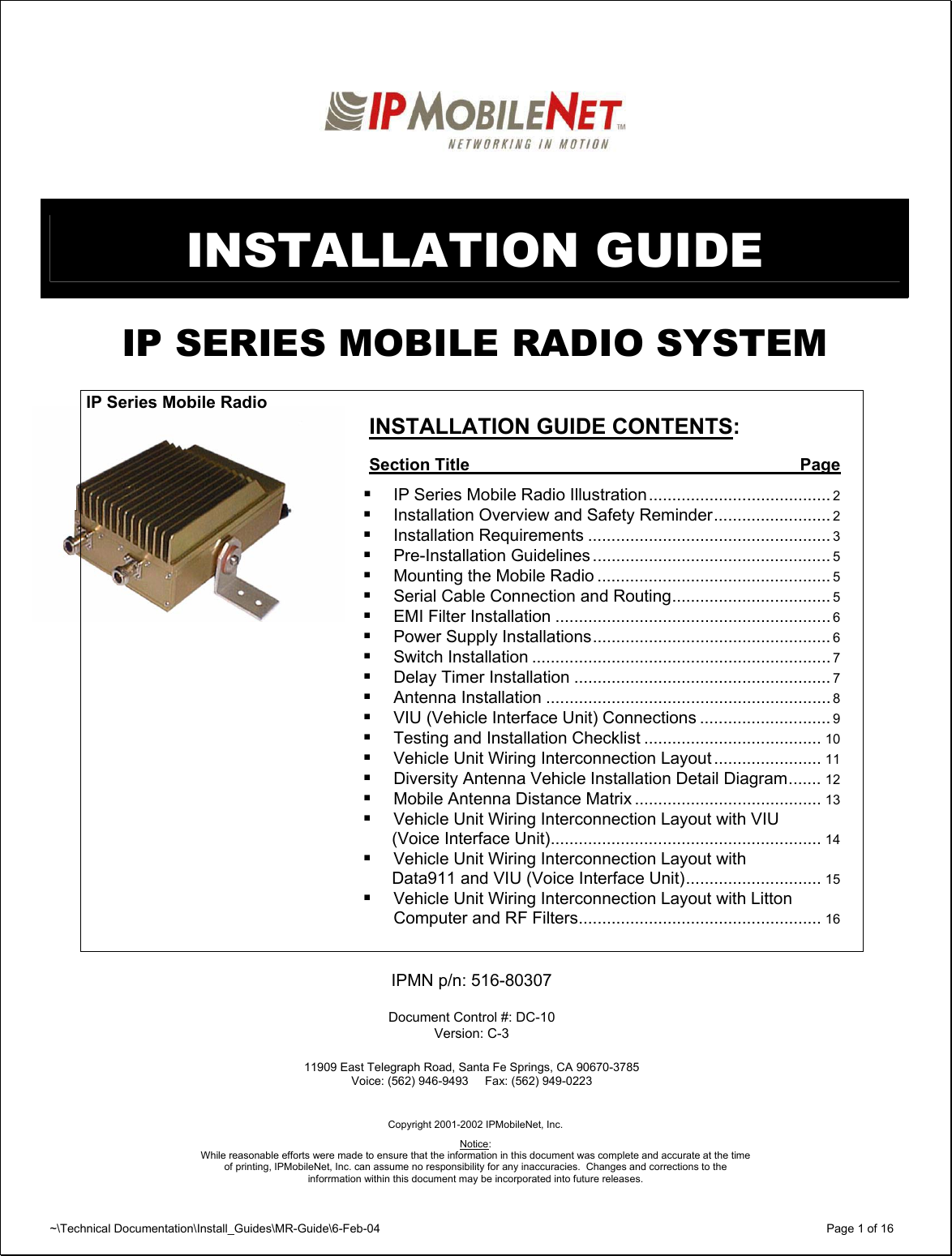
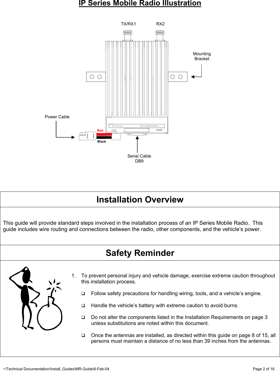
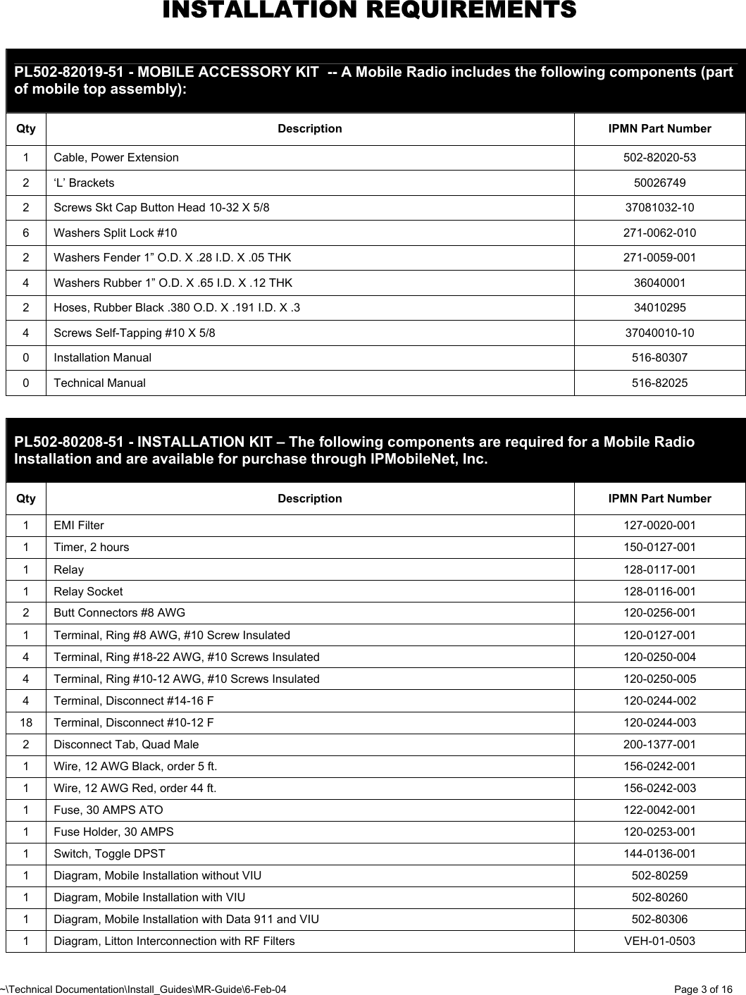
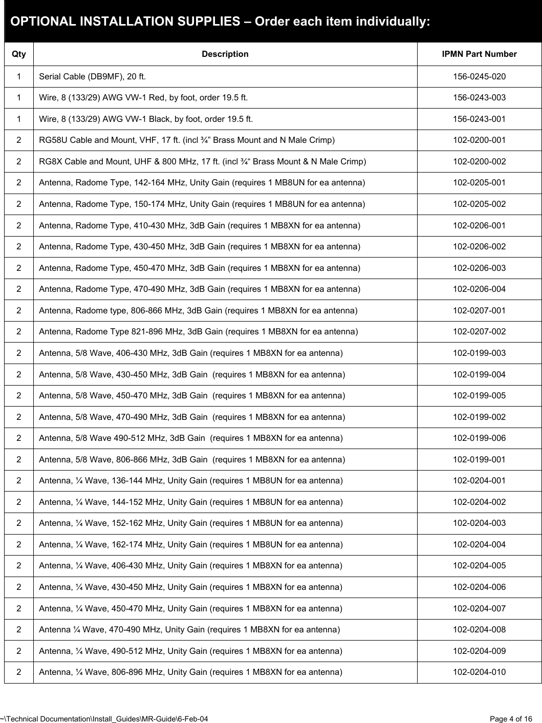
Installation Manual
Contents
1.
Users Manual
2.
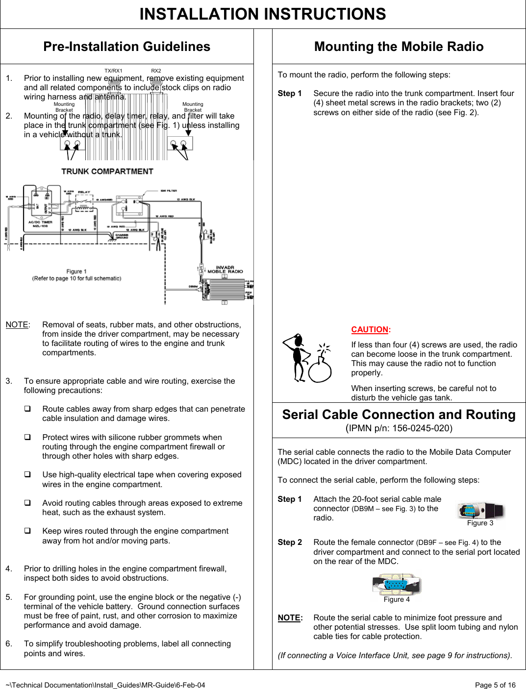
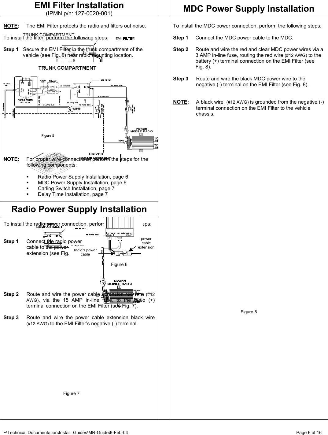
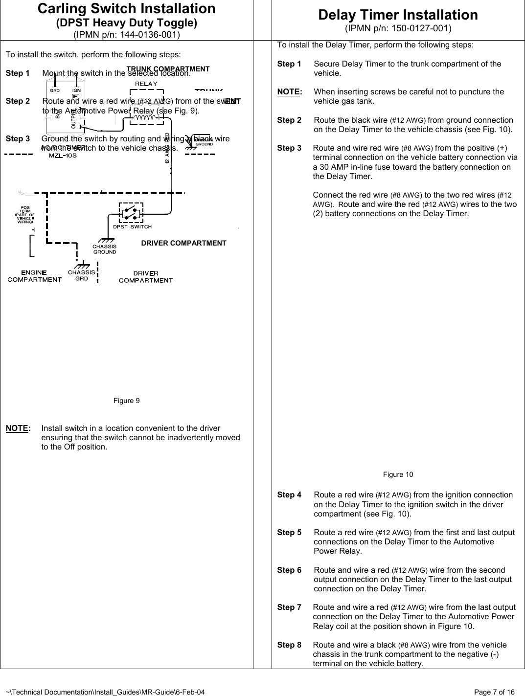
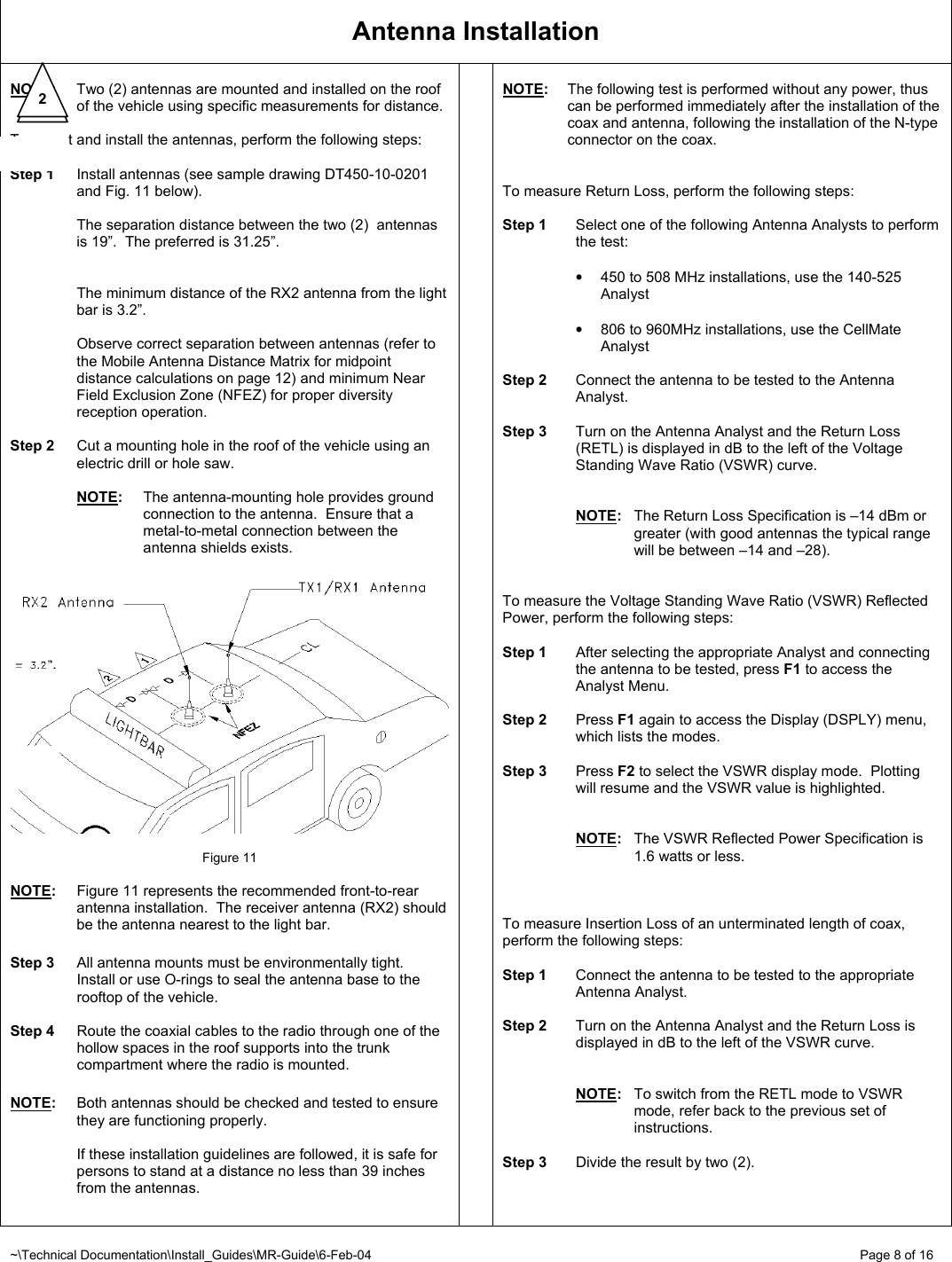
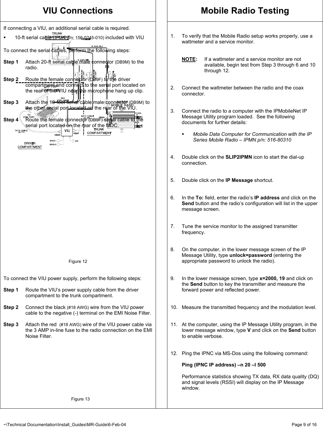
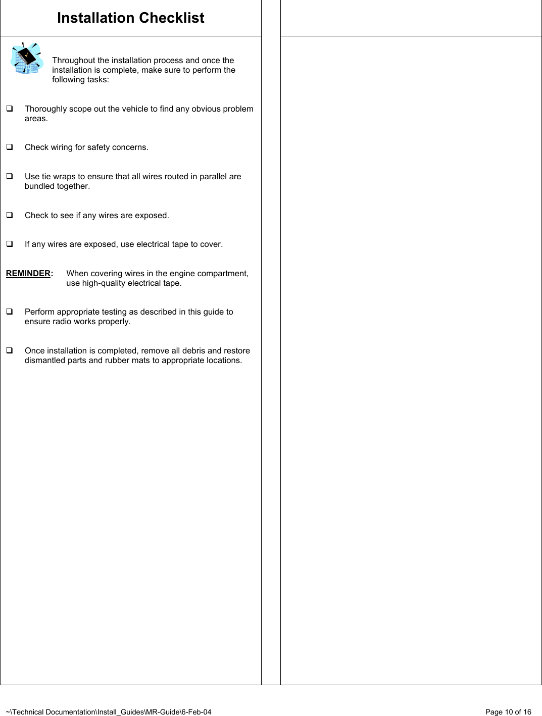
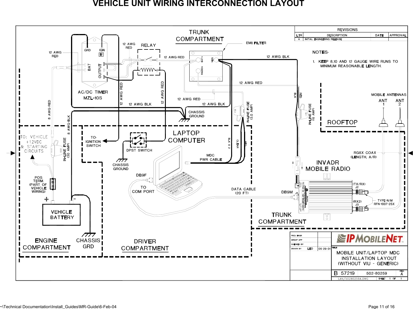
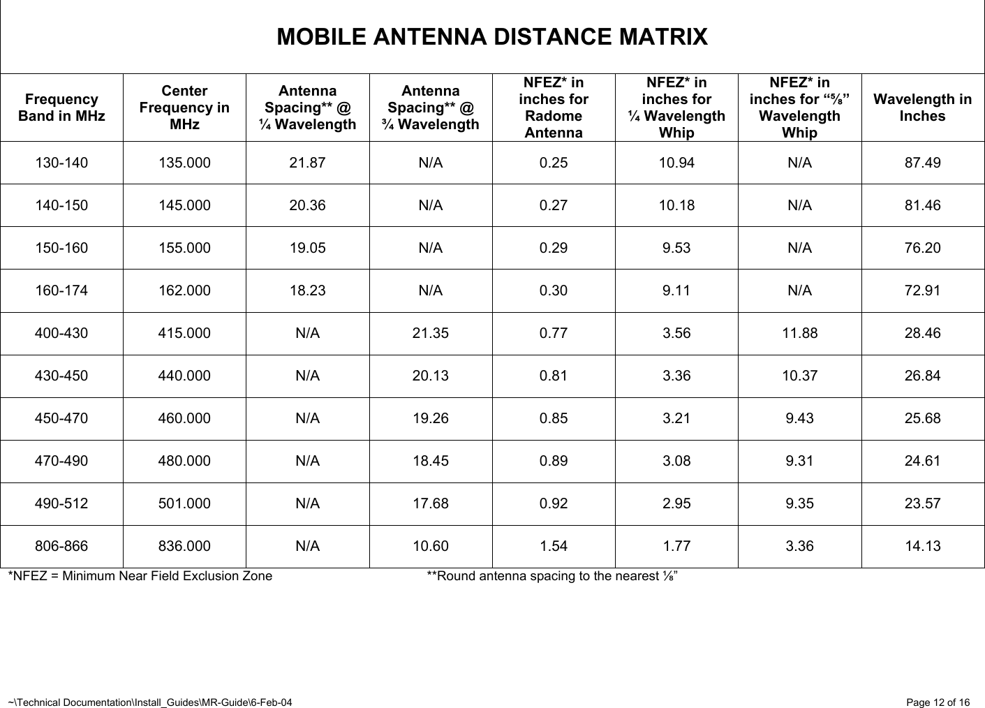
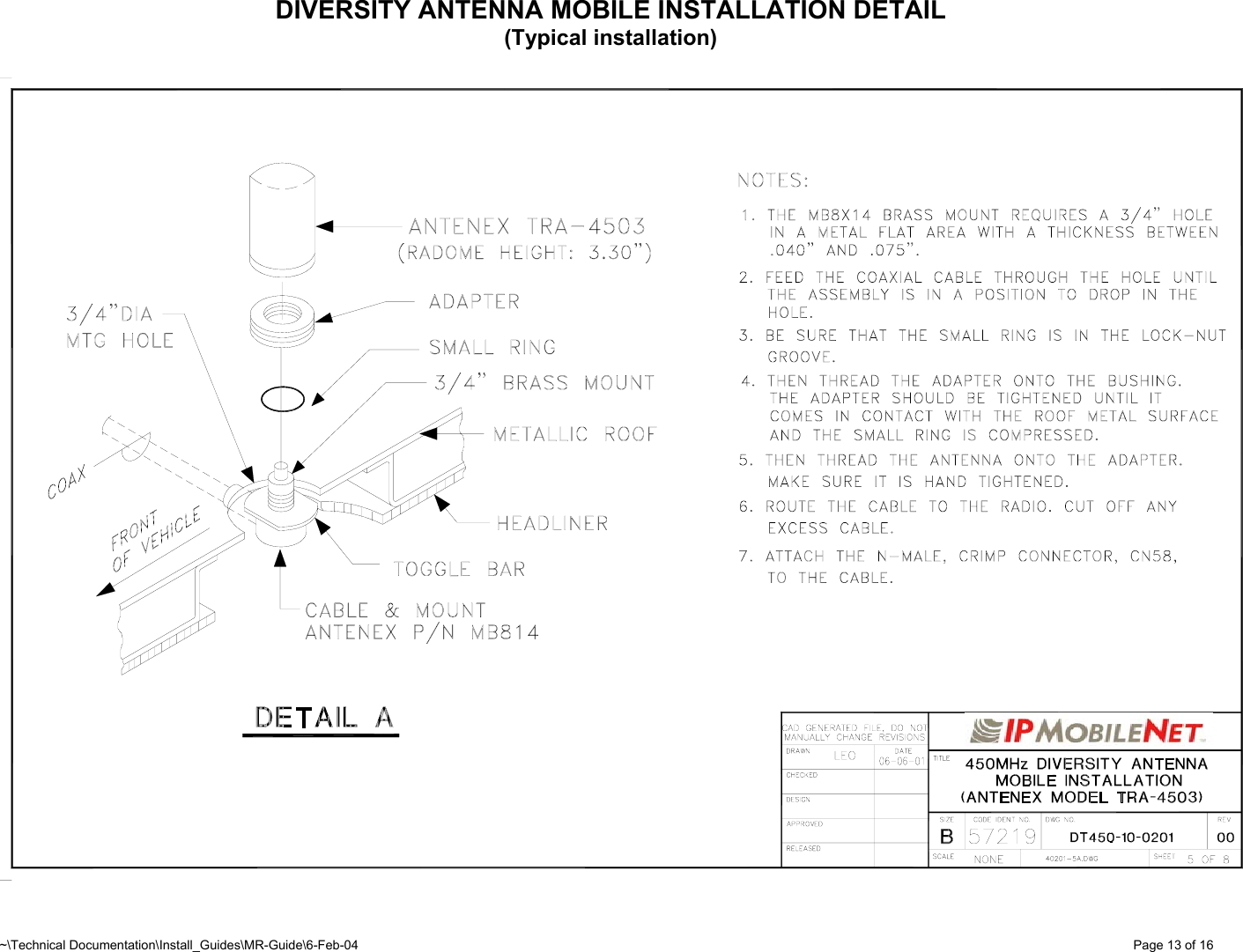
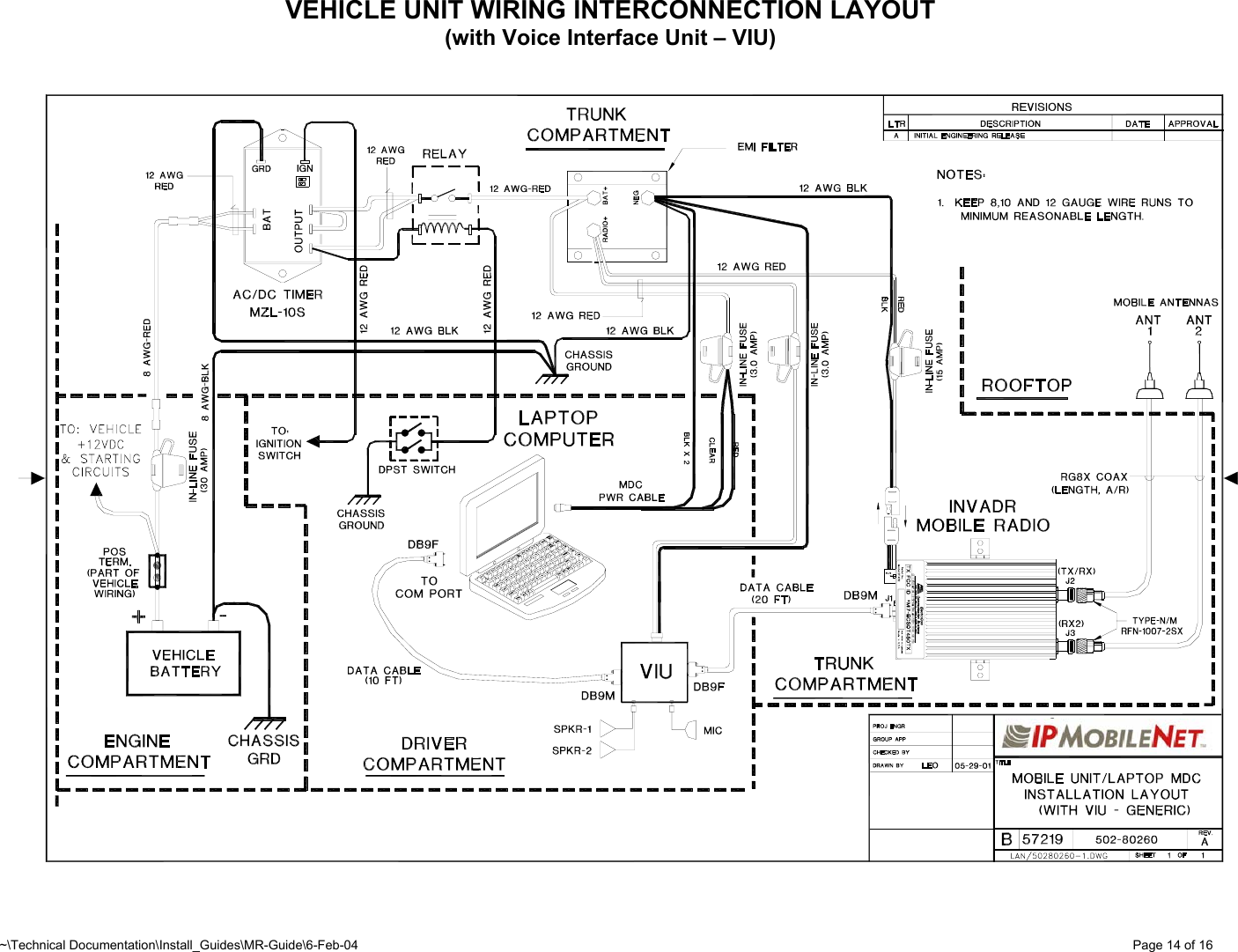
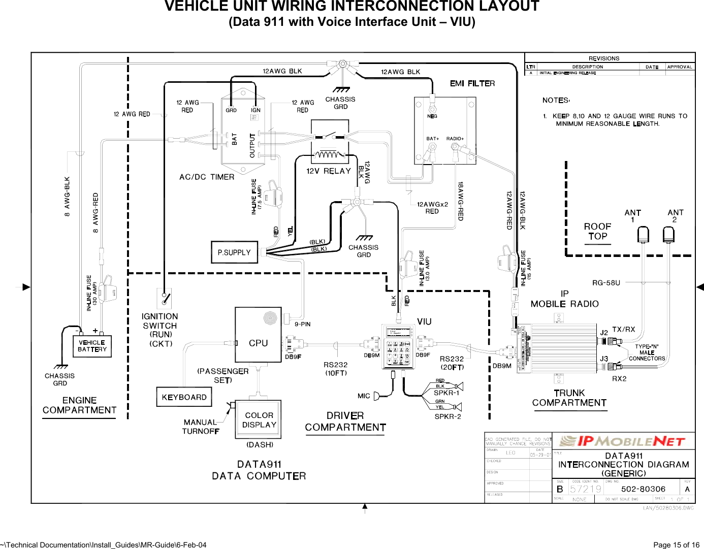
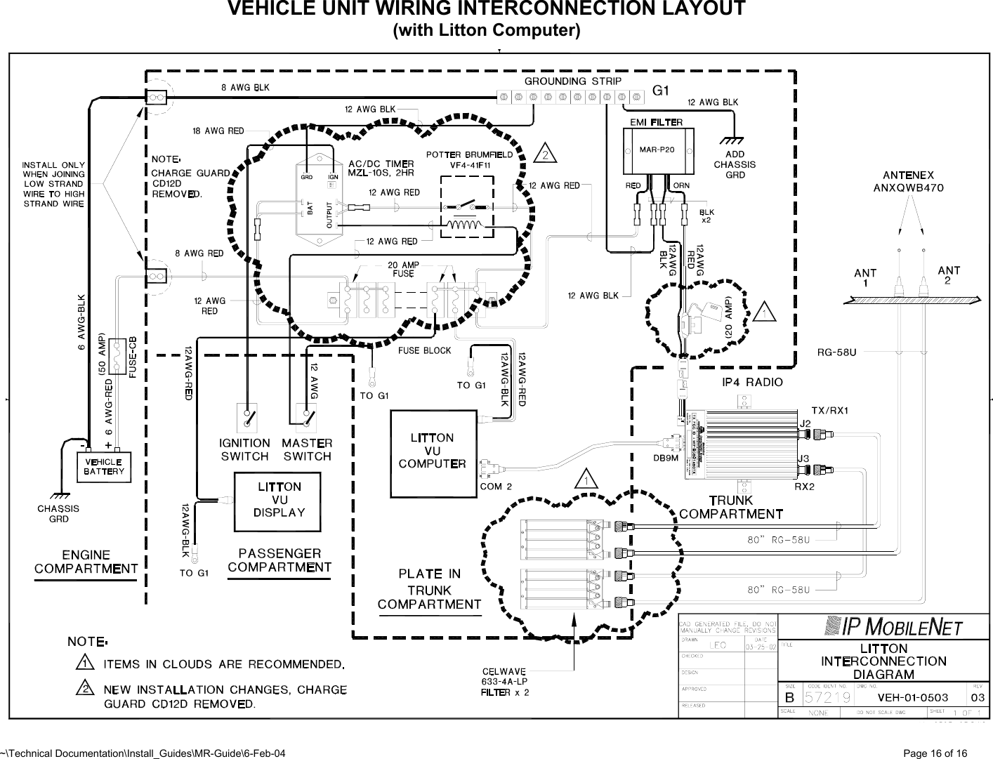
Installation Manual
3.
RF Exposure Training
Installation Manual
Navigation menu
Upload a User Manual
Namespaces
Wiki Guide
HTML
PDF
Info
Views
User Manual
Discussion / Help
Navigation