IPICO Australia 3271-3 High Performance UHF fixed reader User Manual Exhibit 8 UHF RFID Reader 109
IPICO Australia High Performance UHF fixed reader Exhibit 8 UHF RFID Reader 109
UserManual.wiki
>
IPICO Australia
>
3271 3 User Manual
Exhibit 8
Navigation menu
Upload a User Manual
Namespaces
Wiki Guide
HTML
PDF
Info
Views
User Manual
Discussion / Help
Navigation
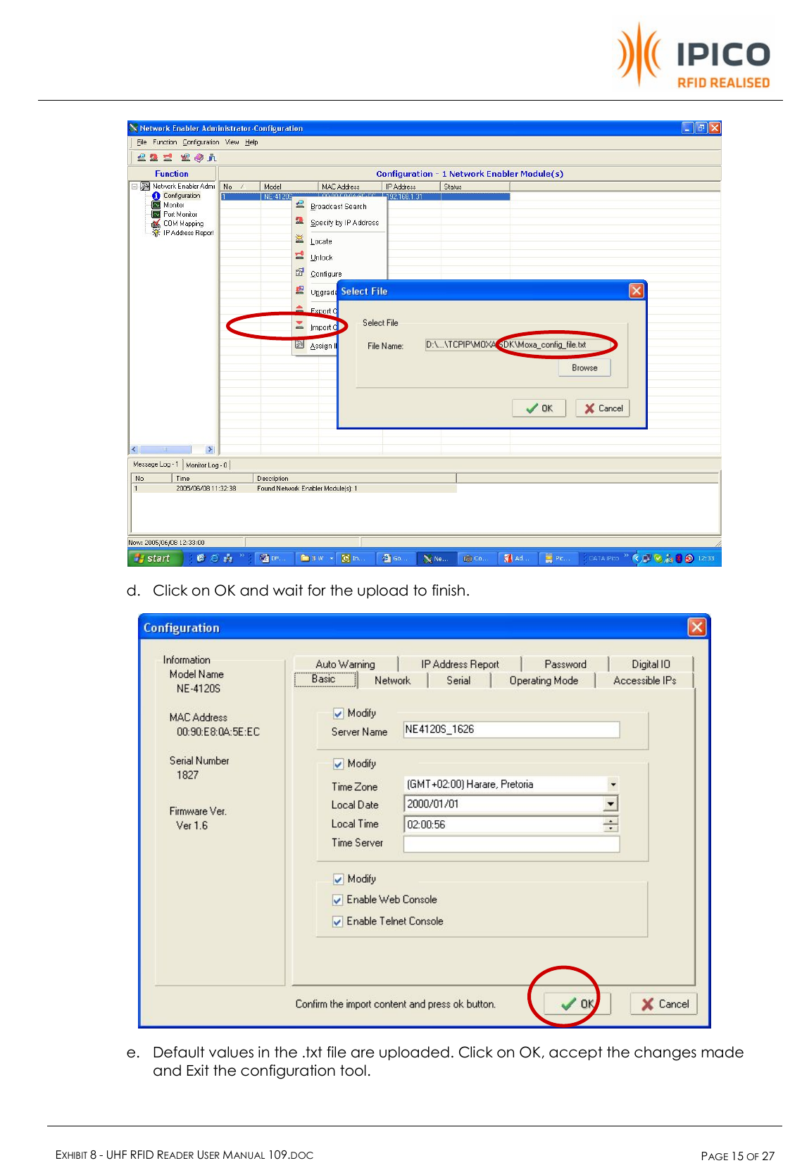
![EXHIBIT 8 - UHF RFID READER USER MANUAL 109.DOC PAGE 24 OF 27 14. Appendix 1: MOXA Ethernet converter Configuration file This is the content of the Moxa_config_file.txt [Network Enabler Configuration File] CheckCode=cfg1 [Basic Information (not changeable)] APID=0x80004100 HWID=0x4129 Serial No=162 MAC Address=00:90:E8:09:63:42 Firmware version=0x1040000 [Basic Settings] Server Name=NE4120S_1626 Time Zone=7200 Time Zone index=31 Date_Year=100 Date_Month=0 Date_Day=1 Time_Hour=2 Time_Minute=0 Time_Second=56 Time_wMilliseconds=0 Time Server= Console Enabled=3 [Network Settings] IP Address=192.168.1.31 Netmask=255.255.255.0 Gateway=192.168.1.1 IP Configuration=0 DNS Server 1=196.25.1.1 DNS Server 2= [SNMP] Enable SNMP=0 Community=public Location= Contact= Trap= [Mail] Mail Server=mail.IPICO.co.za Mail Server Login=1 User Name=jaco Password=jaconel From Address=NE4120S_162@NE4120S To Address1=jaco@IPICO.co.za To Address2= To Address3= To Address4= [Accessible IP List] Enabled=0 Rule1=0,, Rule2=0,, Rule3=0,, Rule4=0,, Rule5=0,, Rule6=0,, Rule7=0,, Rule8=0,, Rule9=0,, Rule10=0,, Rule11=0,, Rule12=0,, Rule13=0,, Rule14=0,, Rule15=0,, Rule16=0,, [Serial] Port1=9600,3,0,1,0, [Operating Mode] Port1=10 [Operating Mode Option 2] Port1=0,0x00,0x00,0 [Operating Mode Option 1] Port1=0,7,4,6543,966 [Auto Warning] Mail=0x1B Trap=0x0 [Port Auto Warning] Port0=0x03,0x00 [IP Address Report] Server= Port=4002 Period=10 [Password] Password=](https://usermanual.wiki/IPICO-Australia/3271-3/User-Guide-1011313-Page-24.png)