IPICO Australia 3271-3 High Performance UHF fixed reader User Manual Exhibit 8 UHF RFID Reader 109
IPICO Australia High Performance UHF fixed reader Exhibit 8 UHF RFID Reader 109
Exhibit 8

EXHIBIT 8 - UHF RFID READER USER MANUAL 109.DOC
PAGE 1 OF 27
Exhibit 8: User Manual
High Performance UHF fixed reader
EXHIBIT 8 - UHF RFID READER USER MANUAL 109.DOC
PAGE 2 OF 27
FCC ID: VHY3271-1
FCC ID: VHY3271-2
FCC ID: VHY3271-3
Version 1.09
August 2008
UHF High performance RFID R
eader
User Manual
EXHIBIT 8 - UHF RFID READER USER MANUAL 109.DOC
PAGE 3 OF 27
Please read instructions before operating this devise.
Warranty is void if you open or tamper with this device.
Explosive atmospheres
User shall switch off this unit and obey all safety requirements in these areas. This unit may only be operated if the area is declared safe by a safety
official. Hazardous areas typically include fuelling areas, below decks on boats, fuel or chemical transfer/storage points, blasting locations and
areas where air contains chemicals or particles, such as grain, dust or metal powders.
FCC ID: VHY3271-1, 902.5-908.8 band
FCC ID: VHY3271-2, 915.3-921.6 band
FCC ID: VHY3271-3, 921.2-927.5 band
FCC DECLARATION (USA)
FCC Section 15.19
This device complies with Part 15 of the FCC rules. Operation is subject to the following two conditions:
1. This device may not cause harmful interference.
2. This device must accept any interference received, including interference that may cause undesired operation.
Information to User (FCC section 15.105)
This equipment has been tested and found to comply with the limits for a Class A digital device, pursuant to Part 15 of the FCC rules. These limits
are designed to provide reasonable protection against harmful interference when the equipment is operated in a commercial environment. This
equipment generates, uses and can radiate radio frequency energy and, if not installed and used in accordance with the installation manual,
may cause harmful interference to radio communications. Operation of this equipment in a residential area is likely to cause harmful interference,
in which case you will be required to correct the interference at your own expense.
Information to User (FCC section 15.21)
The user is cautioned that any changes or modifications not expressly approved by IPICO or authorized representative could void the user’s
authority to operate the equipment.
IMPO
RTANT
SAFETY
· Avoid any extended human RF exposure directly in front of the UHF Reader, up to a distance of 30 cm, when unit is switched on.
·
Only authorised personnel may open the unit due to risk of electrical shock. Warranty and certification is void if opened by unauthorised person.
NOTICE
All rights reserved. No part of this document may be reproduced or transmitted in any form or by any means without written permission from
IPICO Inc.
IPICO Inc. shall not be liable for any errors or for incidental or consequential damages in connection with the furnishing, performance or use of
this document, hardware and/or software.
All information in this document including the design and specification are subject to change without notice for the purpose of product
improvement.
For further information contact +27 12 345-9520.
APPROVALS
FCC Part 15 Class A
EN 300-220-1, 300-220-3, ETS 300-683 and EN 6100-3-2& 3 (CE) : Pending
IEC 60950 (CE): Pending
UL 60950/CAN/CSA22.2 No. 60950 : Pending

EXHIBIT 8 - UHF RFID READER USER MANUAL 109.DOC
PAGE 4 OF 27
Table of Contents
Figures .............................................................................................................................................................5
Tables...............................................................................................................................................................5
History..............................................................................................................................................................5
Glossary...........................................................................................................................................................6
1. Supplied goods and accessories........................................................................................................7
2. Cable Connections ..............................................................................................................................8
3. Front panel Indicator..........................................................................................................................11
4. Operations overview ..........................................................................................................................12
5. Reader overview ................................................................................................................................12
6. Installation and Set-up .......................................................................................................................13
8. Application notes ...............................................................................................................................16
9. Troubleshoot .......................................................................................................................................20
10. Maintenance ......................................................................................................................................20
11. Technical specification......................................................................................................................21
12. Support................................................................................................................................................22
13. Technical Assistance..........................................................................................................................22
14. Appendix 1: MOXA Ethernet converter Configuration file...............................................................24
15. Appendix 2: Typical EVI setup: Overhead and Road side...............................................................25
EXHIBIT 8 - UHF RFID READER USER MANUAL 109.DOC
PAGE 5 OF 27
FIGURES
Figure 1 Supplied goods and accessories.......................................................................................7
Figure 2 RS 232 (Default) and Mains Power Connection ...............................................................8
Figure 3 RS 232 (Default) and DC 12V Power Connection ............................................................8
Figure 4 RS 232 to RS 485 Converter connection (optional) ..........................................................9
Figure 5 Ethernet connection (optional) ......................................................................................10
Figure 6 Reader status indicator.....................................................................................................11
Figure 7 UHF Integrated Reader Overview....................................................................................12
Figure 8 EVI Reader Orientation .....................................................................................................16
Figure 9 EVI Reader Installation: Side read scenario ....................................................................17
Figure 10 EVI Reader Installation: Overhead read scenario........................................................17
Figure 11 EVI Reader Installation angle .........................................................................................17
Figure 12 Example of multiple EVI reader installation for Free flow tolling/spotting...................18
Figure 13 Examples of sunshades for harsh environments ...........................................................19
Figure 14 Typical ENP tag location and orientation............................................................................19
TABLES
Table 1 Frequency selection guide................................................................................................18
Table 2 Troubleshoot guide ............................................................................................................20
Table 3 Technical Specifications....................................................................................................21
HISTORY
Version Date Person Reason
1.00 2002-01-18 HLvE Create and issued for review from documents supplied by WHH and MvD
1.01 2002-02-19 WHH Add ShowTags ver. 1.0 information
1.02 2002-02-20 MVD Format document for release
1.03 2002-02-28 MVD Update
Firmware (v5.3), ShowTag ver. 1.01, Figure 7, Par 7.4.4.7, Figure 8, Table 4
Appendix A: All Acknowledgement commands
1.04A 2002-02-28 MVD Update
Firmware (v5.5 only available with RFU v2.00), ShowTag ver. 1.04, add Figure3, add
Figure10, Move ShowTag to Appendix A. Move command set to Appendix B
1.05 2002-05-08 MVD Add German Safety instruction.
1.06 2002-06-20 MVD Add CE and FCC Pre-Compliance Approval and update technical specification
1.07 2003-02-12 MVD Remove protocol description from this manual. Refer to protocol manual for SW
command descriptions. Update technical specification.
1.08 2006-10-10 MVD Change logo and Address to indicate new IPICO status. Update technical
specification.
1.09 2008-08-02 MVD Add FCC information, EVI application notes

EXHIBIT 8 - UHF RFID READER USER MANUAL 109.DOC
PAGE 6 OF 27
GLOSSARY
dB Decibels
dBd Antenna gain in dB relative to dipole antenna
dBi Antenna gain in dB relative to isotropic antenna
dBil Antenna gain in dB relative to linearly polarized isotropic antenna
EIRP Effective Isotropic Radiated Power (measured in dBi or dBil)
ERP Effective Radiated Power (referred to a dipole) (measured in dBd)
EVI Electronic Vehicle Identification
I and Q Quadrature RF signals (90 deg out of phase)
RFID Radio Frequency Identification
RFU Radio Frequency Unit
CW Continuous Wave
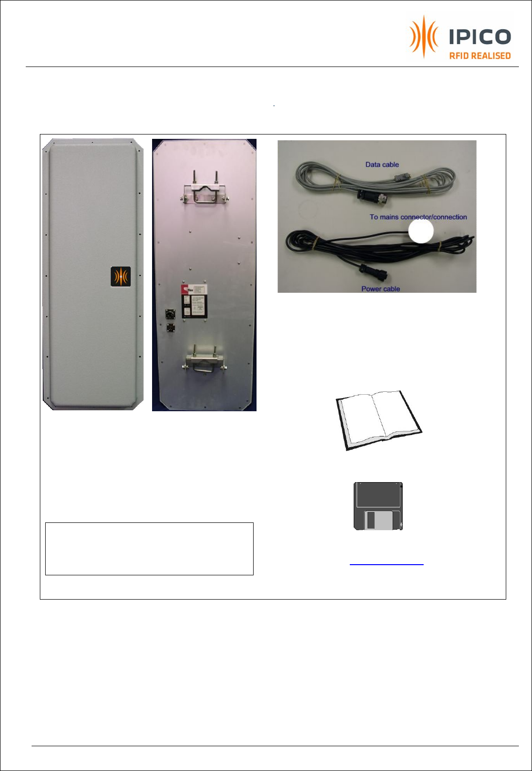
EXHIBIT 8 - UHF RFID READER USER MANUAL 109.DOC
PAGE 7 OF 27
Reader front view
Rear view of Reader
Note the included pole
mounting brackets.
TOP: Data communication cable (shipped with 6m cord)
BOTTOM: Power cable (shipped with 6m cord)
Please consult your local dealer for different cable assemblies
User Manual and Demo software are
available on WWW.IPICO.COM
User Manual
NOTE:
Please refer to the technical specification
or contact your local dealer on the different reader
configurations available.
1. Supplied goods and accessories
Figure 1 Supplied goods and accessories
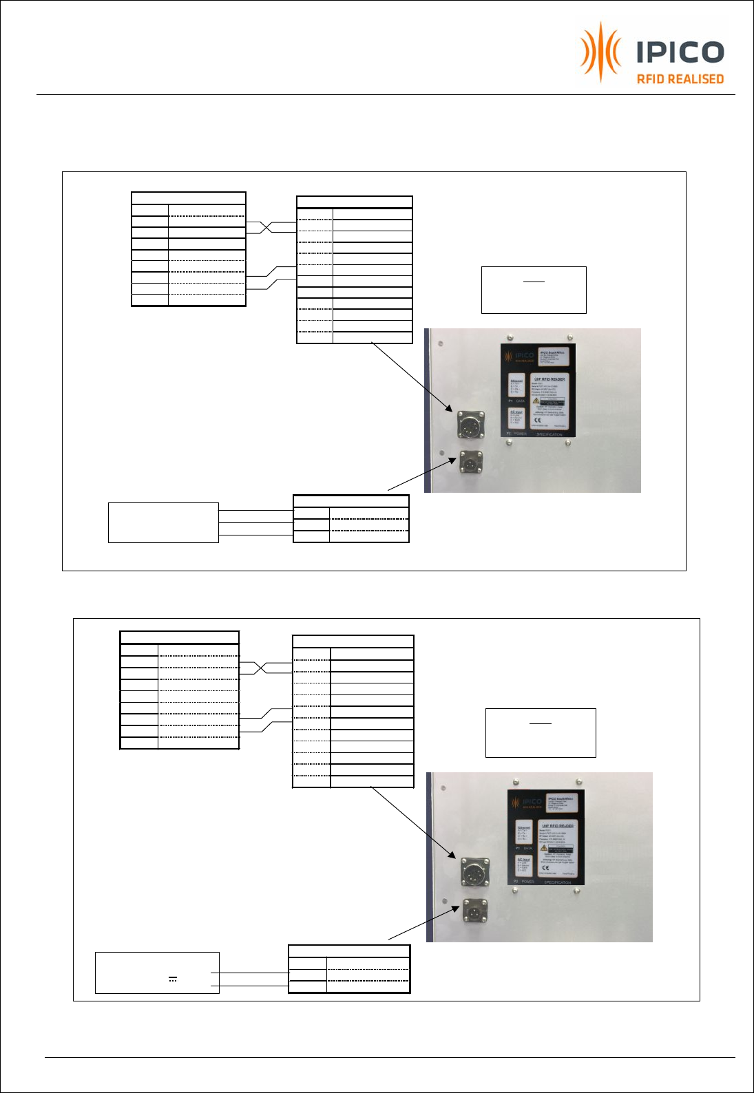
EXHIBIT 8 - UHF RFID READER USER MANUAL 109.DOC
PAGE 8 OF 27
2. Cable Connections
To PC 9p Female D type
Pin 1
Nc
2
Receive Data
3
Transmit Data
4
Nc
5
Signal Ground
6
Nc
7
RTS
8
CTS
9
Nc
P1 DATA (12P Female)
Pin A
Nc
B
Receive Data
C
Transmit Data
D
Nc
E
Signal Ground
F
CTS
G
RTS
H
Nc
J
Nc
K
Nc
L
Nc
M
Nc
P2 POWER (3P Female)
Pin 1
Live
2
Neutral
3
Earth
Brown
Blue
Green/Yellow
Connect to AC power
source
(AC 90-264V ~ 1.4A 50-60Hz)
Note
Chassis internally
connected to Earth
Figure 2 RS 232 (Default) and Mains Power Connection
To PC 9p Female D type
Pin 1
Nc
2
Receive Data
3
Transmit Data
4
Nc
5
Signal Ground
6
Nc
7
RTS
8
CTS
9
Nc
P1 DATA (12P Female)
Pin A
Nc
B
Receive Data
C
Transmit Data
D
Nc
E
Signal Ground
F
CTS
G
RTS
H
Nc
J
Nc
K
Nc
L
Nc
M
Nc
P2 POWER (3P Female)
Pin 1
Nc
2
+12V
3
GND
Brown
Blue
Connect to DC power
source
(11.7-12.3VDC 2.5A)
Note
Chassis internally
connected to GND
Figure 3 RS 232 (Default) and DC 12V Power Connection
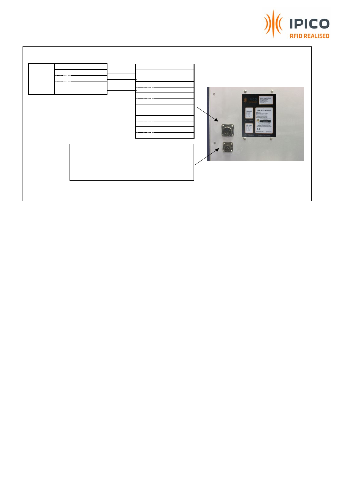
EXHIBIT 8 - UHF RFID READER USER MANUAL 109.DOC
PAGE 9 OF 27
Figure 4 RS 232 to RS 485 Converter connection (optional)
Note: The RS 232 to RS485 converter is used to increase the distance between the reader and the
host controller (typically a PC). Distances between the reader and host can be up to 1.2 km with baud
rates not exceeding 100kbps. In case the host is not equipped with a 25Pin (male) secondary serial
port, a 25 to 9 pin adapter must also be used to connect to the host. This connection allows for full-
duplex, point-to-point communication only. The converters supplied by IPICO are optically isolated.
The optically isolated converter, at the PC, must be powered from an external power supply
(included).
The readers do not support a RS 485 multi-drop protocol due to the amount of data throughput. Up to
4 readers can be clustered and connected via RS232 to a iP-DIMI-SA-4 controller that support a wired
and wireless (optional) Ethernet connection. The iP-DIMI-SA-4 also supports 4 isolated inputs and 4
potential free N/O outputs. Readers may also interface to the outside world via RS232/Ethernet
converters. This allows the readers to communicate to an iP-DIMI-SA-8 or iP-DIMI-SA-32 via hubs for
intelligent local control/buffering as well as clustering/zoning of readers.
Other medium and protocol converters are available on request. They include but are not limited to 802.11b
Wireless LAN, Wiegand, Lonworks™, RS232-to-fiber optic etc. In the latter case, the DATA connection will be two
ST-ST bulkhead connectors for multimode fibers. Please refer to IPICO support for more information regarding these
options.
P1 DATA (12P Female)
Pin A
Transmit +
B
Transmit -
C
Receive -
D
Receive +
E
Nc
F
Nc
G
Nc
H
Nc
J
Nc
K
Nc
L
Nc
M
Nc
SCREW TERMINALS
Pin 4
Receive +
3
Receive -
2
Transmit -
To PC com
port via
25P
Female
1
Transmit +
Refer to Figure 2 or 3 for Power connection
Isolated Converter powered by an
external PSU
Green
Yellow
Blue
Red
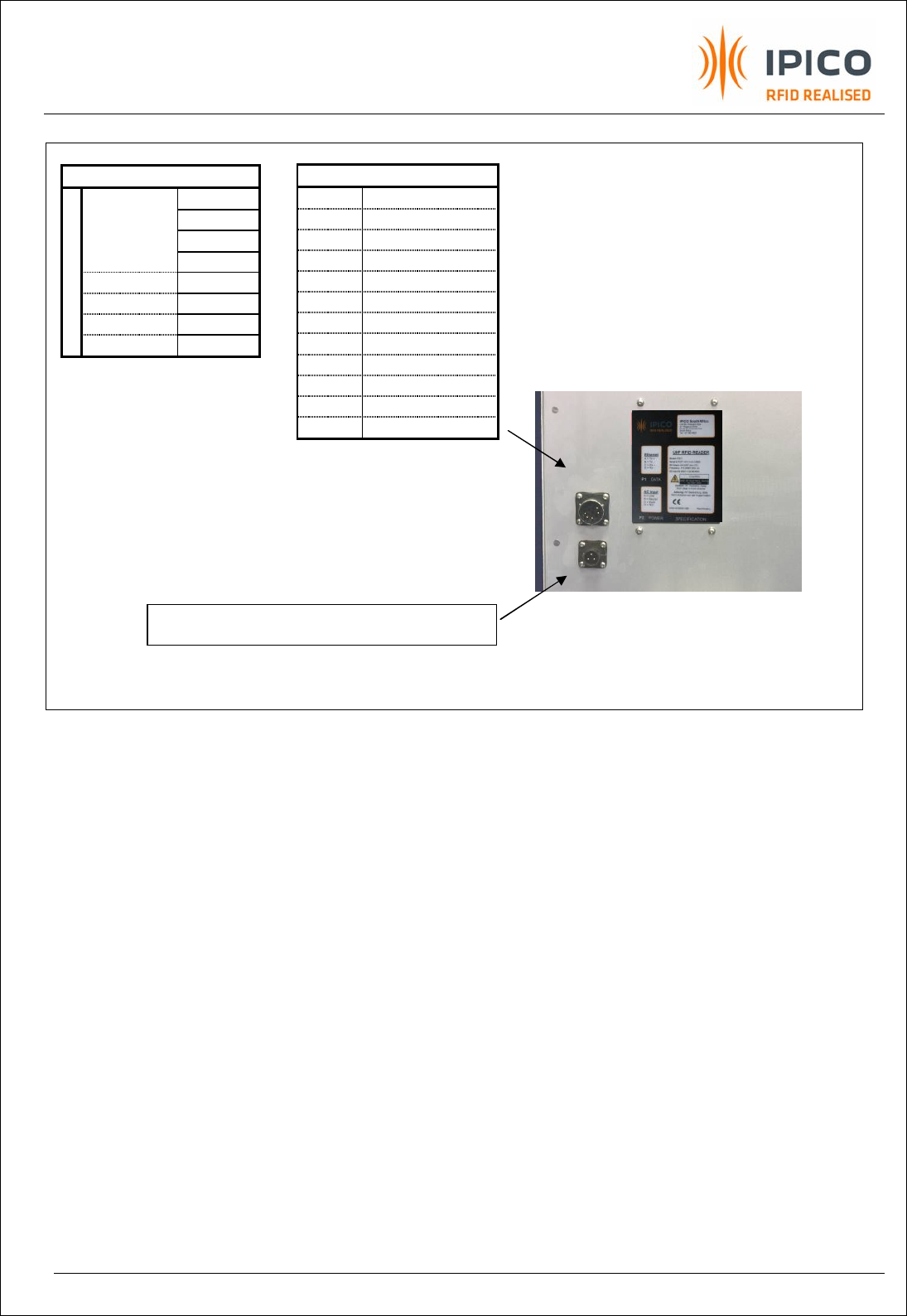
EXHIBIT 8 - UHF RFID READER USER MANUAL 109.DOC
PAGE 10 OF 27
Figure 5 Ethernet connection (optional)
RJ45 (Wiring according T568A)
1
Green/White Transmit +
2
Green Transmit -
3
Orange/White Receive +
4
Blue NC
5
Blue/Wht NC
6
Orange Receive -
7
Brown/wht NC
8
Brown NC
P1 DATA (12P Female)
Pin A Transmit +
B Transmit -
C Receive +
D Receive -
E Nc
F Nc
G Nc
H Nc
J Nc
K Nc
L Nc
M Nc
Refer to Figure 2 or 3 for Power connection

EXHIBIT 8 - UHF RFID READER USER MANUAL 109.DOC
PAGE 11 OF 27
3. Front panel Indicator
Figure 6 Reader status indicator
A tri-colour LED will indicate the following reader status to the operator
· Steady RED light indicates Power ON but no processor/communication activity.
· Slow GREEN Flash at 1/6Hz indicates Internal processor working.
· Fast GREEN Flash at 1/2Hz indicates communication activity between reader and
controller/PC.
· Random GREEN fast Flash indicates that a valid Tag ID is decoded.
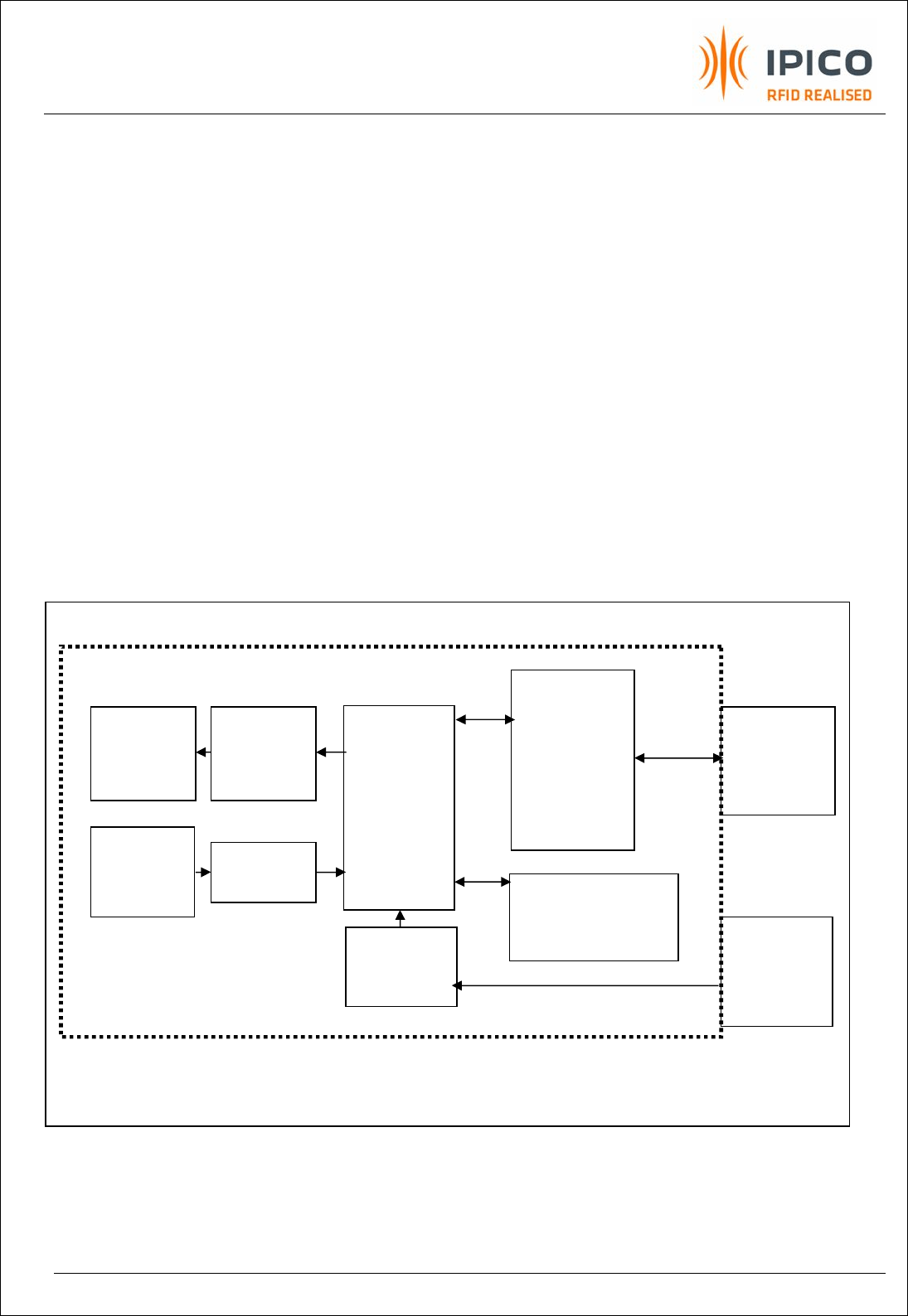
EXHIBIT 8 - UHF RFID READER USER MANUAL 109.DOC
PAGE 12 OF 27
TX Circular
Patch
Antenna
RX Circular
Patch
Antenna
RF Unit
and
Decoder
Status Indicator
and internal
interface board
Build-in PSU
(Optional)
12 Pin
Circular
Connector
Data port P1
Protocol /
Medium
converter
3 Pin
Circular
Connector
Power port P2
1GHz
Low Pass
Filter
13dBm
Attenuator
4. Operations overview
The IPICO reader is designed as a read/write (RW) reader. The reader modulates READ commands to
the tags in order to interrogate the tag. Depending on the application new DATA can be updated on
the tag using a modulated WRITE command. Read commands will typically be 5ms in duration with a
response from the tag in 300us for 64bits. A WRITE command will typically be longer and will average
around 35ms.
During a read event, the reader will energise a tag(s) (can be a few milliseconds i.e 7ms), followed by
modulating a READ command in order to ‘get’ DATA from the tag. The reader decode the incoming
signal and place a time/date stamp on it, whilst buffering the data temporarily until such time it can
be send, on the communication port, to the host. If multiple DATA pages are received from the same
tag before the packet is send to the host, a hit counter is increased. This hit count is included in the
communication packet to the host. The RF unit does a full quadrature down conversion, and both in-
phase and quadrature phase signal (I and Q) are decoded.
5. Reader overview
Figure 7 UHF Integrated Reader Overview
RS 232

EXHIBIT 8 - UHF RFID READER USER MANUAL 109.DOC
PAGE 13 OF 27
6. Installation and Set-up
Note: The following set-up is for demonstration purpose only. Installation and applications will be site
dependant.
1. Install ShowTags on the controlling PC running on Windowsä 95,98 NT or 2000. It consists of a
single .EXE file, which can be copied from the supplied 3.5” disk to any directory on the
controlling PC and run from that directory. From time to time updates are available on the
Web at http://www.IPICO.com
2. Start ShowTags. Check the serial port settings. The readers’ serial port factory setting is
9600bps, no flow control, no parity, but it will remember the last setting used. The default setting
for ShowTags is the same, but the setting can be changed and saved.
3. Mount the reader on an overhead structure facing downwards (height depending on reader
range and tagged object size) or vertically on a pole to such height that the horizontal
centreline of the reader is inline with the tags on the objects.
4. Connect the RS 232 serial cable (default option) from the reader to a serial port on the
controlling PC. Refer to Figure 4 for RS 485/422 connection.
5. Connect the Power cable from the reader to the correct power source. Remember there are two Input
power supply options – Mains AC or external DC 12V – Refer to Figure 2.or Figure 3 for the correct wiring
diagram.
6. Apply power to the RF unit. Refer to the technical specification regarding the Input voltage
requirements for the reader.
7. Present tags into the reader beam.
8. Use ShowTags as a debugging tool to view the tag reading results and to evaluate the
different reader commands.
9. The User’s application software can now be implemented.
10. Standard HP readers must be mounted in a Vertical orientation to comply with an IP 65 rating.
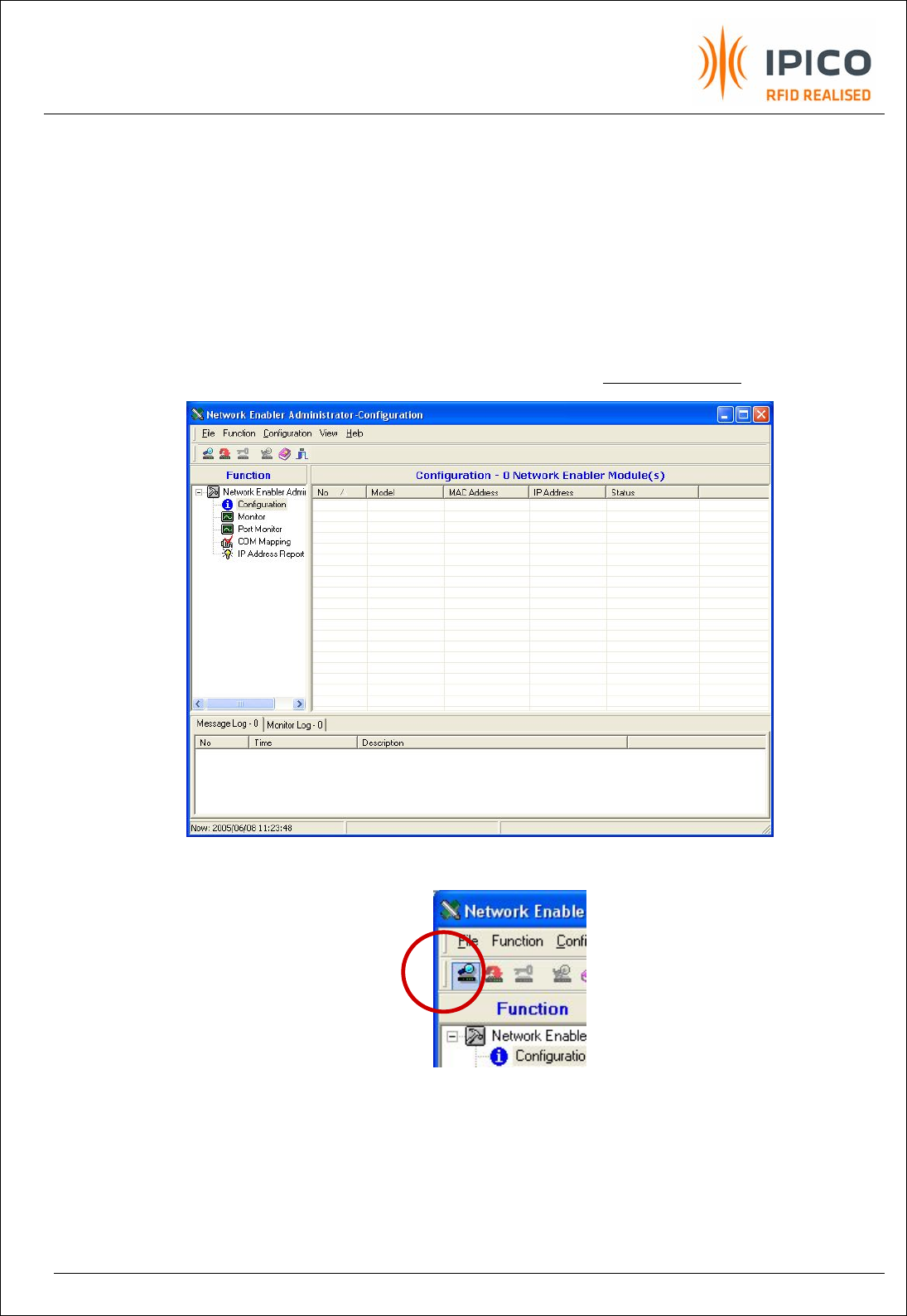
EXHIBIT 8 - UHF RFID READER USER MANUAL 109.DOC
PAGE 14 OF 27
6.1 Quick start (Ethernet communication)
Connect the Ethernet cable to J20 on the Registration Reader and proceed as follows:
Note: The default factory settings are IP = 192.168.1.31 port 6543
In case the user wants to change IP/port settings of the reader, edit the file in Appendix 1 and upload
the file to the reader by doing the following procedure:
a. Open the Moxa SDK tool. (Download from support at www.IPICO.com)
b. Do a broadcast search and select the reader that is found
c. Right click on selected reader and go to “Import Configuration”
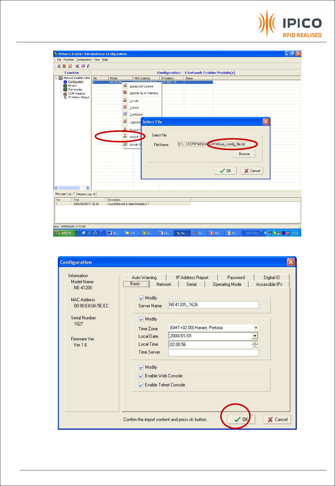
EXHIBIT 8 - UHF RFID READER USER MANUAL 109.DOC
PAGE 15 OF 27
d. Click on OK and wait for the upload to finish.
e. Default values in the .txt file are uploaded. Click on OK, accept the changes made
and Exit the configuration tool.
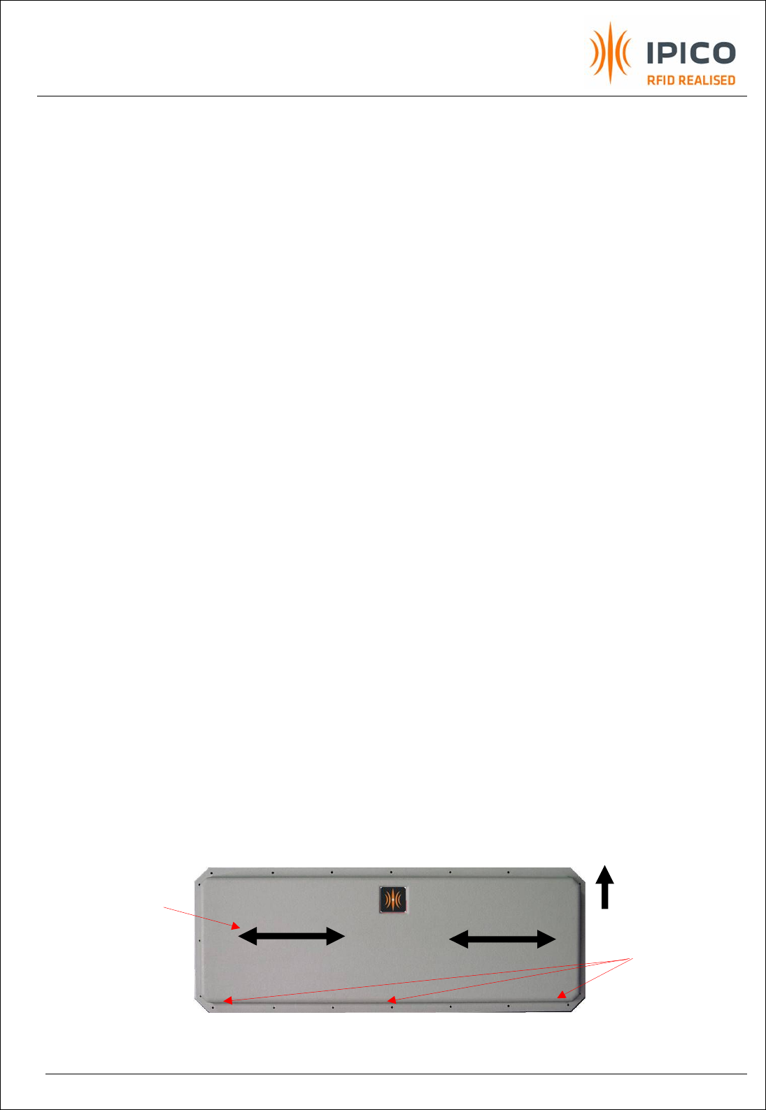
EXHIBIT 8 - UHF RFID READER USER MANUAL 109.DOC
PAGE 16 OF 27
8. Application notes
1. Some of the IPICO tag antenna formats are dipoles. Like dipoles, they have nulls end-on.
2. Tags should always be orientated in a plane orthogonal to the direction to the reader.
3. Reading speed depends on the tag version used. Please consult IPICO’s support team or your
local dealer regarding these specifications.
4. Up to 30 tags can be read per second. This depends however on the total number of tags
present in the reader beam at the same time The reading speed will reduce when more than
30 tags are present simultaneously.
5. V3 tags are recommended when a small numbers of fast moving tags are scanned (< 30 tags
@ > 15 m/s). When a large numbers of tags must be scanned simultaneously, it is
recommended to use V5 tags (> 120 tags @ < 3 m/s). Please consult your local dealer
regarding these options.
6. Read ranges in excess of 20 m are achievable at 30 W EIRP (USA site licensed). At 4 W EIRP
(USA unlicensed) the read range is about 8 m and at 500 mW, ERP (Europe) the read range is
about 3 m.
7. Readers operating in small confined spaces can “jam” themselves due to unwanted
reflections. Two readers operating simultaneously in close proximity from each other may also
influence each other. Please consult IPICO’s support team or your local dealer regarding
possible multiplexing/screening strategies.
8. The standard dipole tags must be mounted at least 18 mm away from a metallic or
conductive surface, fluids and human bodies. Refer to IPICO’s range of packaged tags in
order to plan an application.
9. Reflections from nearby conducting surfaces and multi-path propagation in particular can
lead to nulls in the reader field.
10. Readers can be ordered with different data interfaces. Standard is RS232. Optional are
Ethernet, Isolated Wiegand, Isolated RS485. Please consult your local dealer regarding such a
configuration.
11. Please take note that EVI readers are fitted with 2 Linear polarised antennas and must be
mounted correctly, namely horizontally. An arrow on the data plate shows the UP orientation.
Note that there are 3 drainage holes on the bottom edge of the dome.
Figure 8 EVI Reader Orientation
Drain holes
Antenna
Polarisation
This side UP
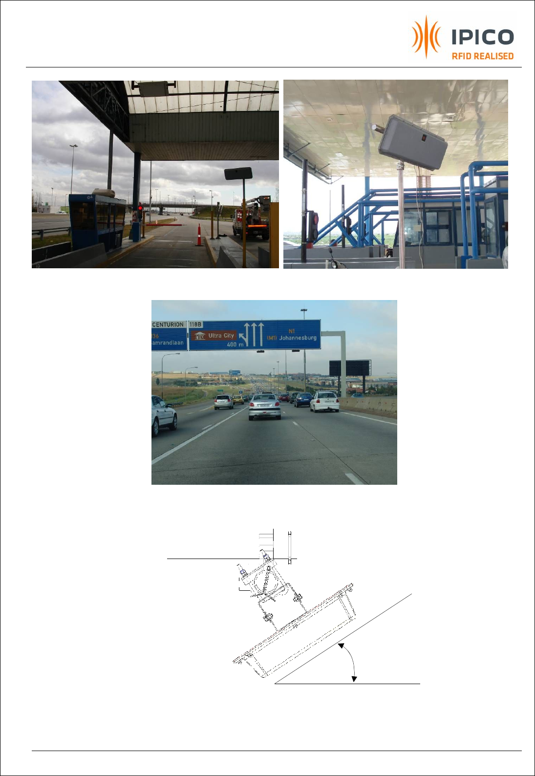
EXHIBIT 8 - UHF RFID READER USER MANUAL 109.DOC
PAGE 17 OF 27
Figure 9 EVI Reader Installation: Side read scenario
Figure 10 EVI Reader Installation: Overhead read scenario
Figure 11 EVI Reader Installation angle
Overhead: 30
°
- 40
°
Roadside: 40° - 90°
Note:
Typical angle is also a function of
height above ground and is site
dependant. Surrounding structures
may cause unwanted reflections or
extended read capabilities. The
installer needs to test and re-adjust for
best performance.
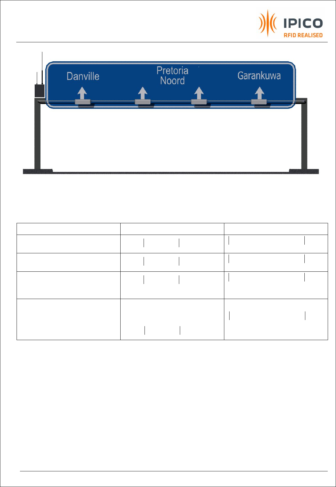
EXHIBIT 8 - UHF RFID READER USER MANUAL 109.DOC
PAGE 18 OF 27
Figure 12 Example of multiple EVI reader installation for Free flow tolling/spotting
Note:
nfreq
R= Reader frequency allocations (these are country and site dependable)
Fixed Frequency Frequency Hopping
Free flow overhead EVI readers with Std
decoders
MHzRR freqfreq 6
21 ³- MHzRR seqhopFreqseqhopFreq 6) )2(1( ³-
Free flow overhead EVI readers with DSP
decoders
MHzRR freqfreq 1
21 ³- MHzRR seqhopFreqseqhopFreq 1) )2(1( ³-
Non Free flow I.e Side readers at Toll
booths with Std decoders or dense
reader applications
MHzRR freqfreq 6
21 ³- MHzRR seqhopFreqseqhopFreq 6) )2(1( ³-
Non Free flow eg. Side readers at Toll
booths with DSP decoders
21 freqfreq RR =
Or
MHzRR freqfreq 1
21 ³-
MHzRR seqhopFreqseqhopFreq 1) )2(1( ³-
Table 1 Frequency selection guide
1freq
R 2freq
R 1freq
R 2freq
R
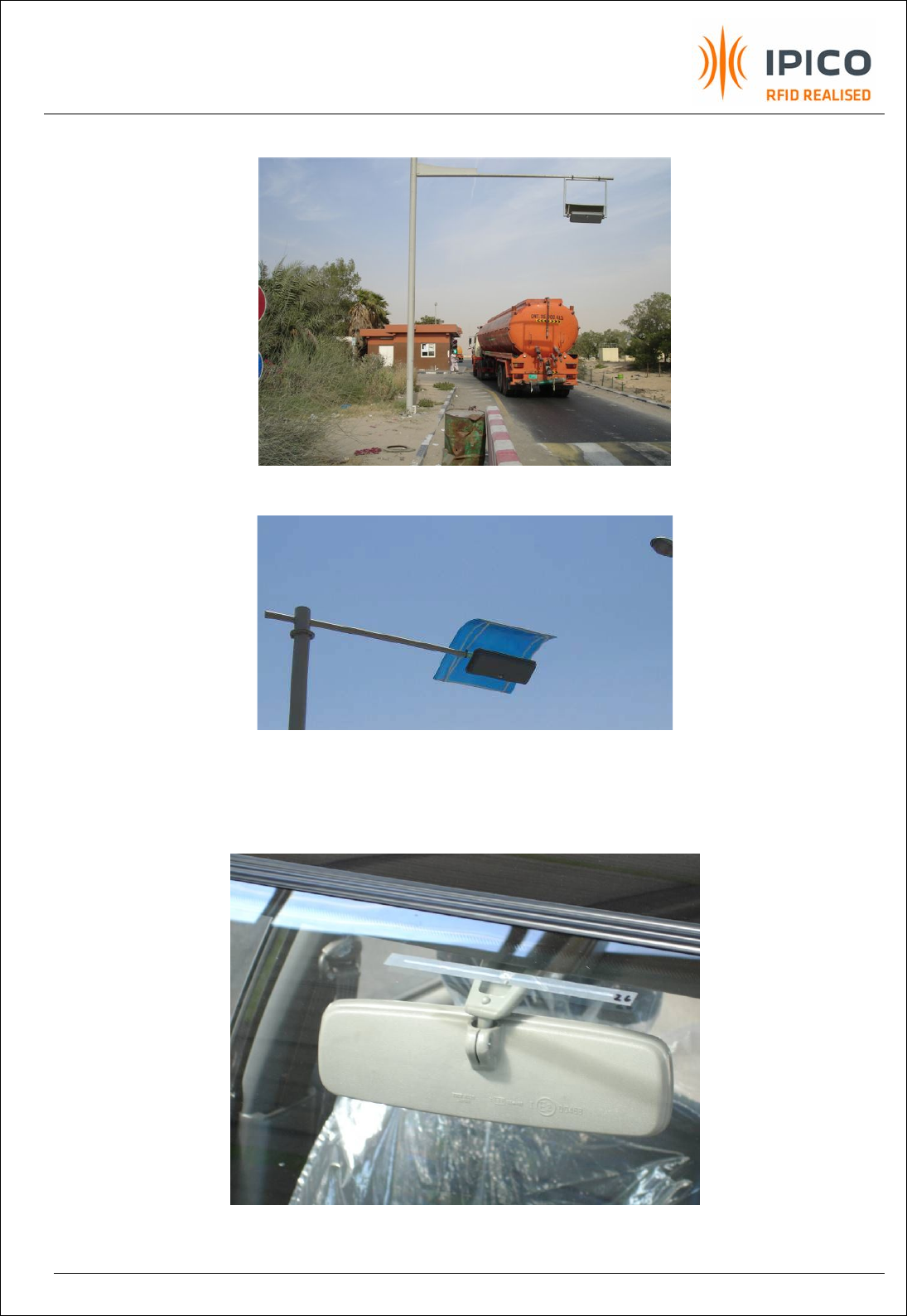
EXHIBIT 8 - UHF RFID READER USER MANUAL 109.DOC
PAGE 19 OF 27
Figure 13 Examples of sunshades for harsh environments
Figure 14 Typical ENP tag location and orientation

EXHIBIT 8 - UHF RFID READER USER MANUAL 109.DOC
PAGE 20 OF 27
9. Troubleshoot
Visual indicator guide
· Steady RED light indicates Power ON but no processor/communication activity.
· Slow GREEN Flash at 1/6Hz indicates Internal processor working.
· Fast GREEN Flash at 1/2Hz indicates communication activity between PC and reader. The fast
heartbeat will only start, once a command has been received by the reader.
· A random GREEN fast Flash indicates a valid Tag ID.
Table 2 Troubleshoot guide
10. Maintenance
This is a low maintenance device. The user must make sure that the reader dome is kept clean and dry
where possible. Any build-up of foreign substances, water or snow will degrade the performance of
the unit.
Symptom Possible causes
Power cord not connected or faulty
Power source faulty
Indicator board faulty
Red LED Off
Reader faulty
Indicator board faulty
Heartbeat of decoder stopped
Steady Red Led with no tags in beam
Reader faulty
Communication Cable not connected or faulty wiring.
Application software not running
Slow Amber flash with no communication possible
between PC and reader
Baud rate incorrect
Transmitter not switched ON (Refer to reader protocol
document).
Faulty Tag
Tag not orientated correctly. (Refer to par 9)
Cannot read a Tag although PC communicates with
reader (fast heartbeat)
Faulty Reader front end
High levels of ambient RF noise operating in the same
frequency spectrum as reader.
Random AMBER fast Flash with no Tag in the beam
Faulty Reader
EXHIBIT 8 - UHF RFID READER USER MANUAL 109.DOC
PAGE 21 OF 27
11. Technical specification
Power supply requirement
Mains input type: 90 - 264 VAC @ ~1.4A, 50/60 Hz
Low voltage input type: 11.7 – 12.3 VDC @ 2.5 A max (typ 600mA for500mW reader)
(12V device is only reversed polarity protected up to 20Vmax. Provision must be made for additional surge protection and regulated
power)
Transmitter power
USA unlicensed: 4 W EIRP (Licensed up to 30W EIRP)
European unlicensed: 500 mW ERP
South Africa: 4 W EIRP
Operating frequency
USA unlicensed: Frequency hopping in the 902-928 MHz ISM band
i. VHY3271-1, Low band : 902.5-908.8 MHz, 64ch, 100 kHz channel spacing
ii. VHY3271-2, Mid band : 915.3-921.6 MHz, 64ch, 100 kHz channel spacing
iii. VHY3271-3, High band: 921.2-927.5 MHz, 64ch, 100 kHz channel spacing
European unlicensed: Fixed frequency in the 869.4-869.65 MHz band
South Africa: Fixed frequency at 915.3 MHz
Antenna type Standard HP reader = Internal 8dBiC (circularly polarized) / (5 dBi linier)
EVI reader = Internal 8dBil (linear polarized)
Read range
Typical read ranges that depends on reader placement and tags used.
USA unlicensed: 6 – 8+ m
European unlicensed: 1 – 3+ m
South Africa: 6 – 8+ m
Communication
Binary or ASCII RS232 with programmable baud rate and flow control
EVI is standard Ethernet enabled
Optional: Isolated RS485/RS422, Ethernet, WLAN 802.11b, Fiber optical.
Data storage
Standard: Internal circular FIFO spool buffer for 64 tags. This data is transmitted to the PC as soon as the communication port is
available.
Optional: Embedded controller for local database and data manipulation (iP-DIMI-SA-4, 8 0r 32)
Electrical interface 12 Pin (P1) circular connecter for DATA (Evaluation kits supplied with 6m cable with 9p D type connector on other side)
3 Pin (P2) circular connecter for POWER (Evaluation kits supplied with 6m cable with no connector on other side)
Environmental
Operating temperature range: -10 to +60 Deg C
Storage temperature range: -20 to +85 Deg C
Humidity: 5 to 95 % non-condensing
IP rating: IP 65 (see mounting details)
UV protection: Yes
Physical
Dimension: 305 (W) x 805 (L) x 60 (H) mm (Height excludes the mounting brackets)
Weight: Approx. 6.5 Kg unpacked
Weight: Approx 10 Kg Packed for shipping
Mounting Two pole mounting brackets. Pole diameter less than 60mm.
Table 3 Technical Specifications

EXHIBIT 8 - UHF RFID READER USER MANUAL 109.DOC
PAGE 22 OF 27
12. Support
Ordering information
Description Model
UHF High Performance reader IP 3271
Frequency Band US (-1, -2 or -3)
Specify other Frequency
Power Supply
12VDC
Mains 90-264VAC 50/60Hz
Communication interface
RS 232
Ethernet
Wiegand
RS 485
Antenna type
EVI (Std 4WEIRP)
HP (Std 500mW ERP or 4WEIRP)
NOTE: Please consult your local dealer for more information regarding the accessories, system design,
frequency and RF power settings.
13. Technical Assistance
IPICO online http://www.IPICO.com

EXHIBIT 8 - UHF RFID READER USER MANUAL 109.DOC
PAGE 23 OF 27
Group
IPICO INC
Ontario, Canada
tel: +1 905 631 6310
fax: +1 905 631 6614
info.can@IPICO.com
www.IPICO.com
Operations
South Africa
Pretoria
tel: +27 12 345 9520
fax: +27 12 345 5834
info.sa@IPICO.com
Australasia
Clontarf, Queensland
tel:+61 7 3889 5799
fax: +61 7 3889 5980
info.aus@IPICO.com
North Asia
Shanghai, China
tel: +86 21 5080 0345
fax: +86 21 5027 8271
info.cn@IPICO.com
China
Beijing, China
tel: +86 10 8280 0541
fax: +86 21 8280 0546
info.cn@IPICO.com
Europe
Valence, France
tel: +33 475 443 238
fax: +33 475 443 238
info.europe@IPICO.com
USA
Georgia, USA
tel: +1 770 552 9654
fax: +1 404 601 9679
info.usa@IPICO.com

EXHIBIT 8 - UHF RFID READER USER MANUAL 109.DOC
PAGE 24 OF 27
14. Appendix 1: MOXA Ethernet converter Configuration file
This is the content of the Moxa_config_file.txt
[Network Enabler Configuration File]
CheckCode=cfg1
[Basic Information (not changeable)]
APID=0x80004100
HWID=0x4129
Serial No=162
MAC Address=00:90:E8:09:63:42
Firmware version=0x1040000
[Basic Settings]
Server Name=NE4120S_1626
Time Zone=7200
Time Zone index=31
Date_Year=100
Date_Month=0
Date_Day=1
Time_Hour=2
Time_Minute=0
Time_Second=56
Time_wMilliseconds=0
Time Server=
Console Enabled=3
[Network Settings]
IP Address=192.168.1.31
Netmask=255.255.255.0
Gateway=192.168.1.1
IP Configuration=0
DNS Server 1=196.25.1.1
DNS Server 2=
[SNMP]
Enable SNMP=0
Community=public
Location=
Contact=
Trap=
[Mail]
Mail Server=mail.IPICO.co.za
Mail Server Login=1
User Name=jaco
Password=jaconel
From Address=NE4120S_162@NE4120S
To Address1=jaco@IPICO.co.za
To Address2=
To Address3=
To Address4=
[Accessible IP List]
Enabled=0
Rule1=0,,
Rule2=0,,
Rule3=0,,
Rule4=0,,
Rule5=0,,
Rule6=0,,
Rule7=0,,
Rule8=0,,
Rule9=0,,
Rule10=0,,
Rule11=0,,
Rule12=0,,
Rule13=0,,
Rule14=0,,
Rule15=0,,
Rule16=0,,
[Serial]
Port1=9600,3,0,1,0,
[Operating Mode]
Port1=10
[Operating Mode Option 2]
Port1=0,0x00,0x00,0
[Operating Mode Option 1]
Port1=0,7,4,6543,966
[Auto Warning]
Mail=0x1B
Trap=0x0
[Port Auto Warning]
Port0=0x03,0x00
[IP Address Report]
Server=
Port=4002
Period=10
[Password]
Password=
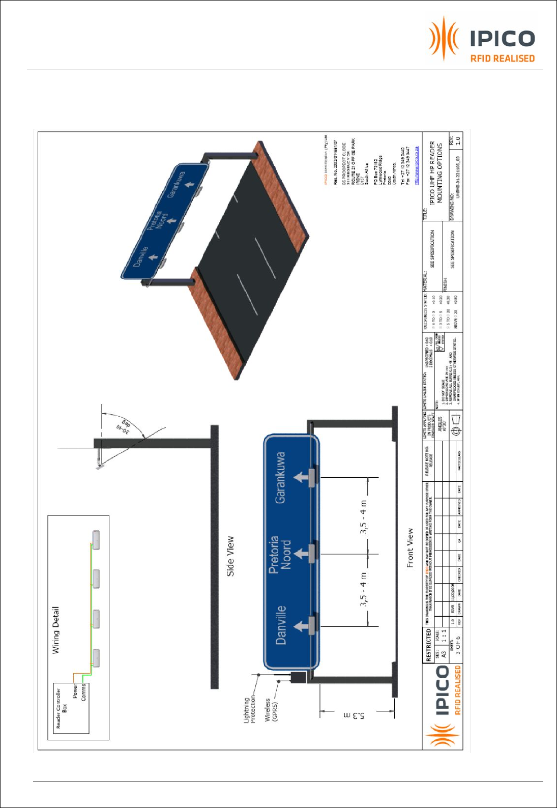
EXHIBIT 8 - UHF RFID READER USER MANUAL 109.DOC
PAGE 25 OF 27
15. Appendix 2: Typical EVI setup: Overhead and Road side
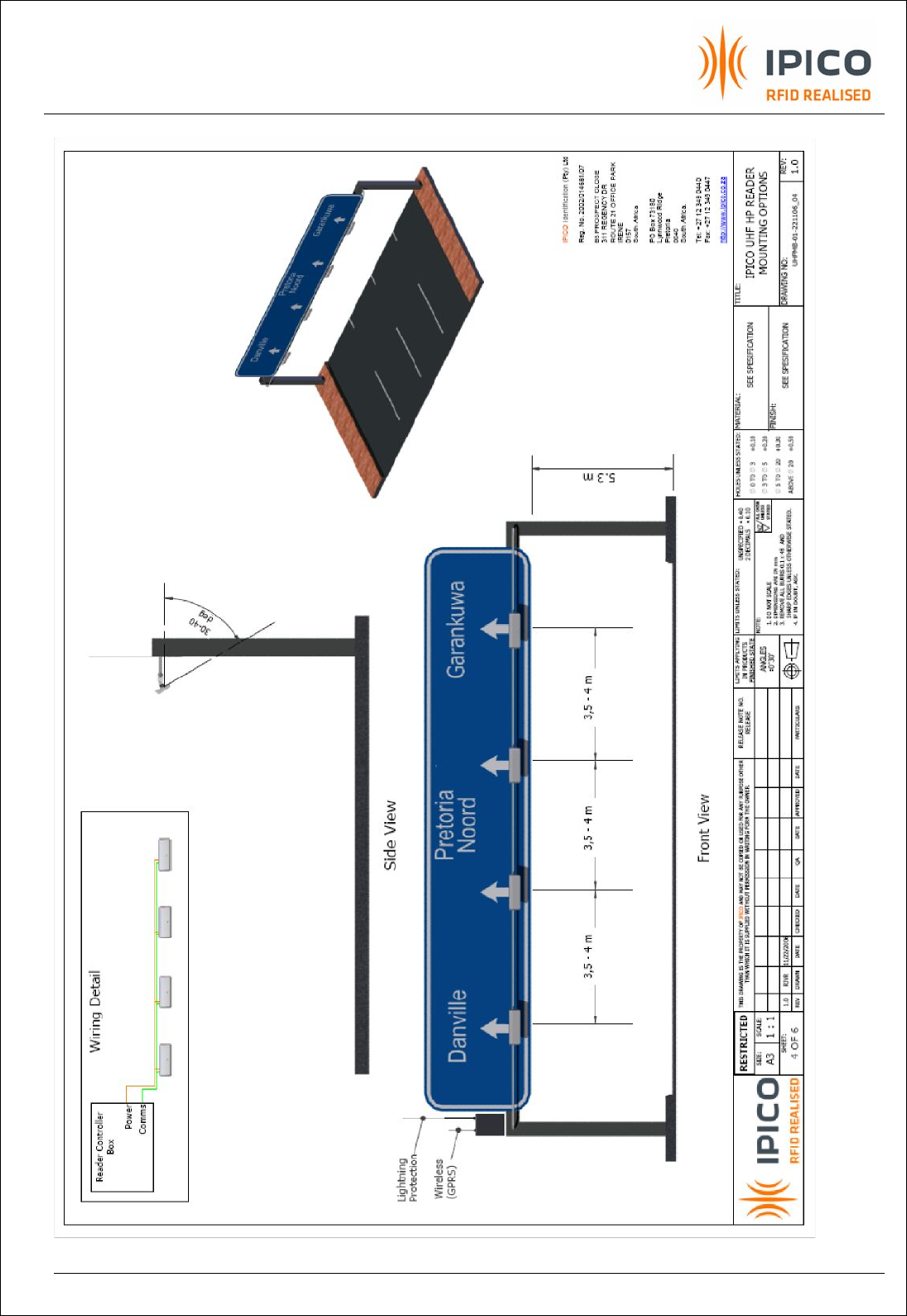
EXHIBIT 8 - UHF RFID READER USER MANUAL 109.DOC
PAGE 26 OF 27
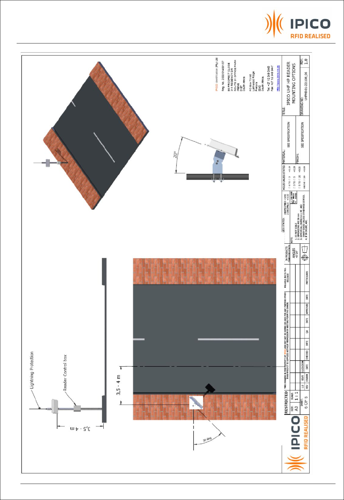
EXHIBIT 8 - UHF RFID READER USER MANUAL 109.DOC
PAGE 27 OF 27
10
°
-30
°