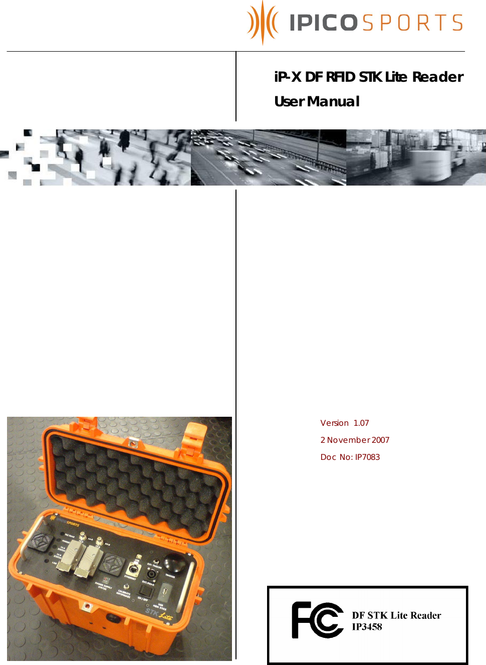
IPICO Australia IP3458A LOW FREQUENCY SPORTS TIMING SYSTEM User Manual STK Lite Manual V1 07 20071102 A
IPICO Australia LOW FREQUENCY SPORTS TIMING SYSTEM STK Lite Manual V1 07 20071102 A
UserManual.wiki
>
IPICO Australia
>
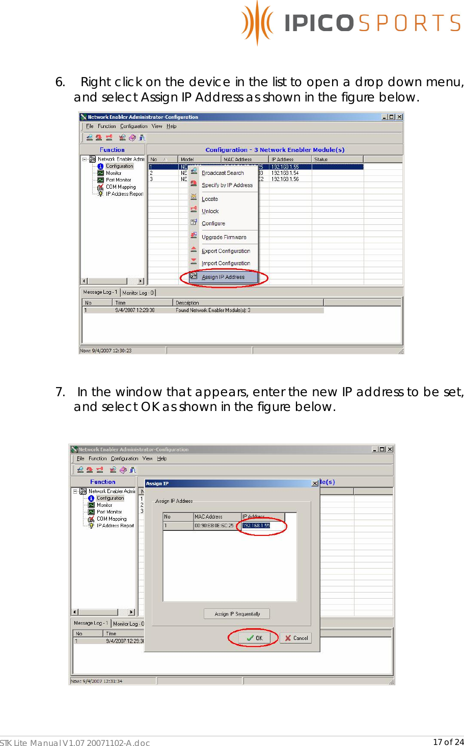
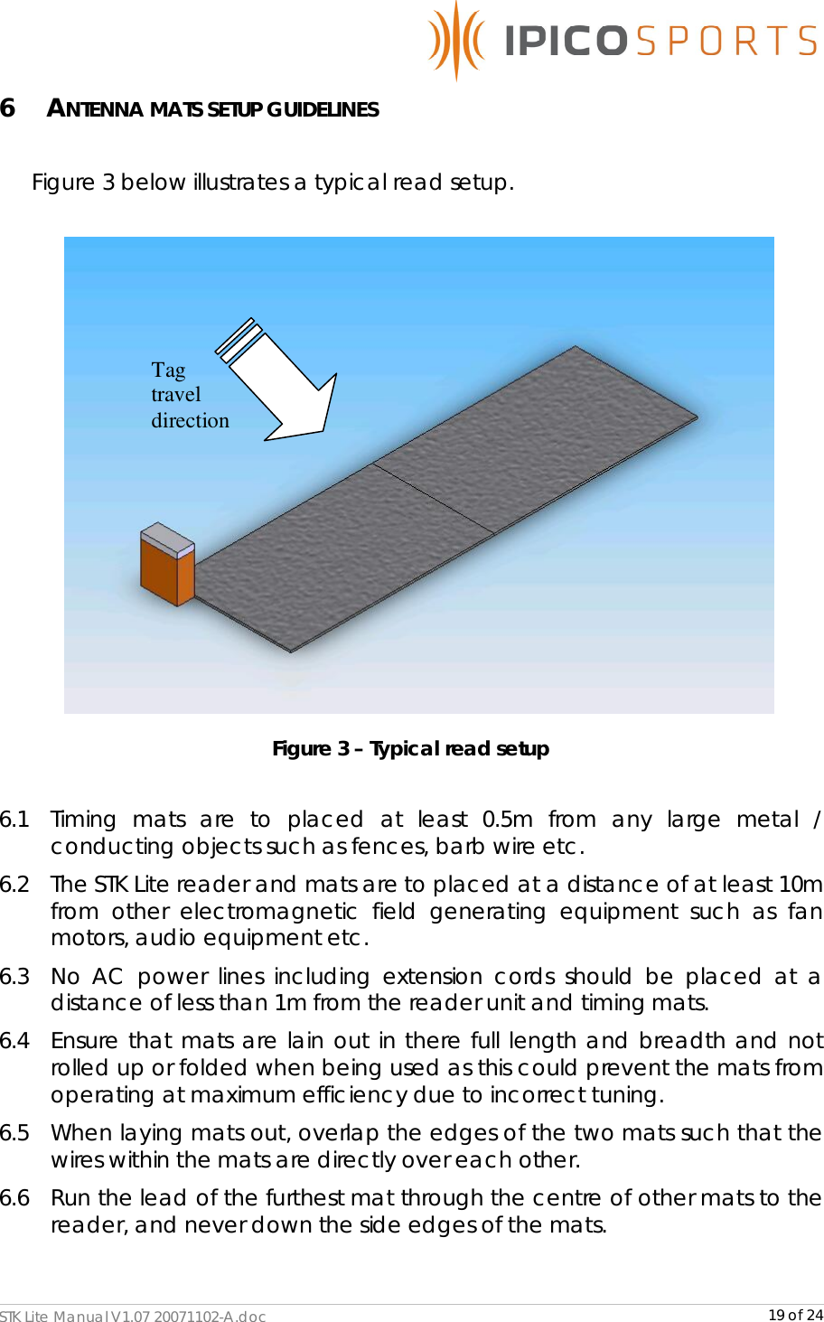
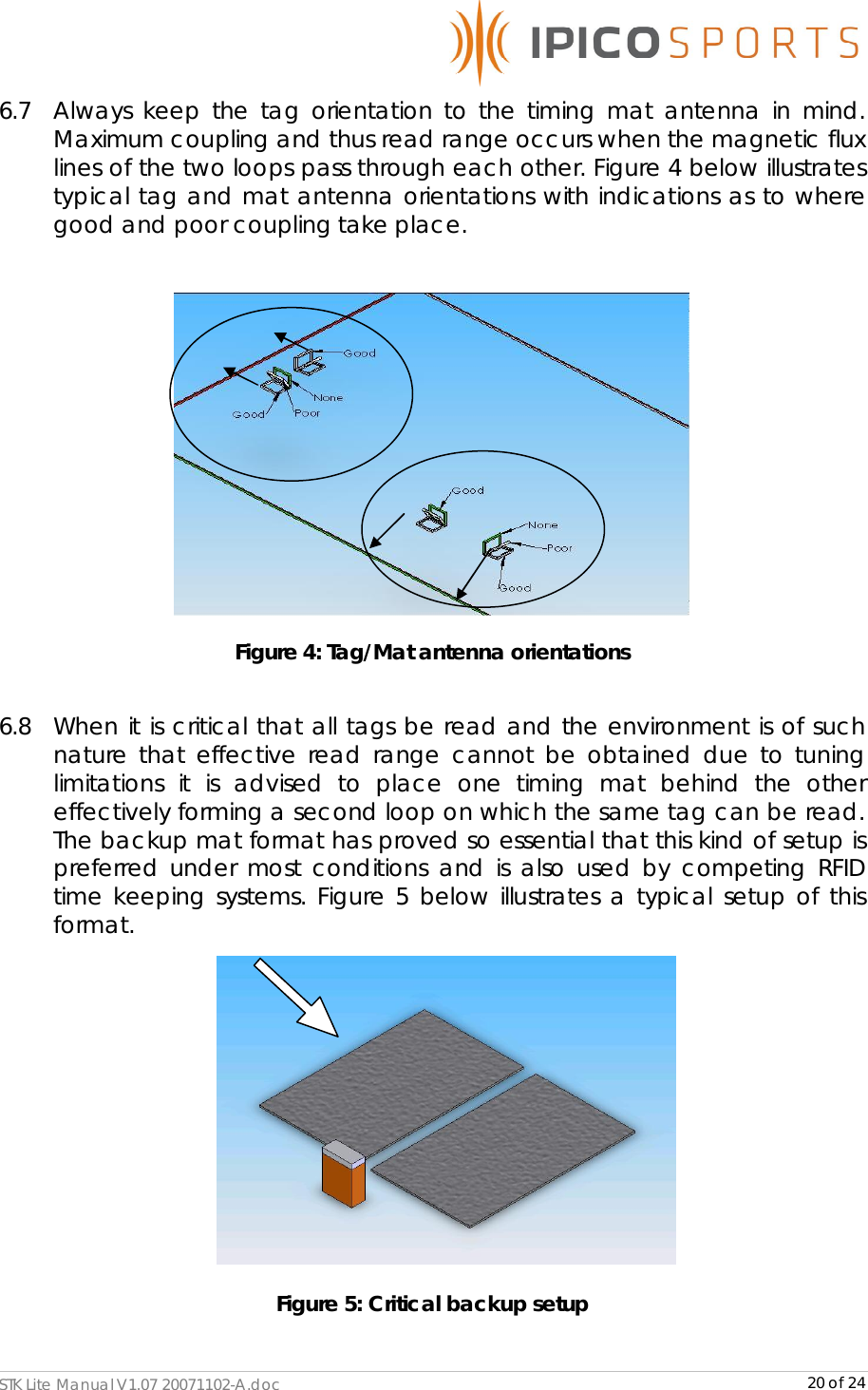
IP3458A User Manual
USERS MANUAL
Navigation menu
Upload a User Manual
Namespaces
Wiki Guide
HTML
PDF
Info
Views
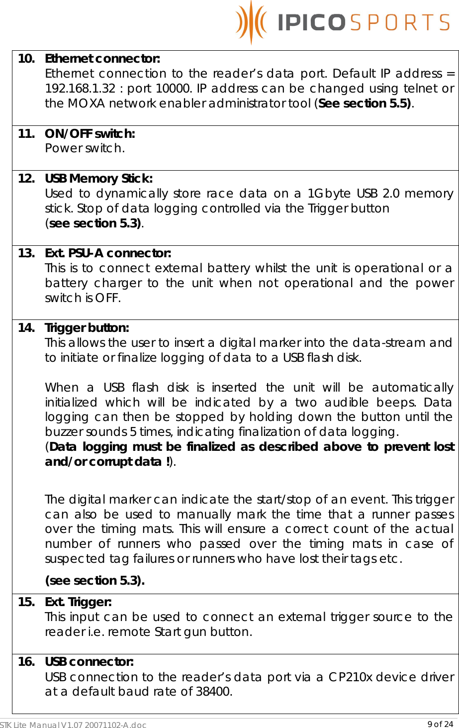
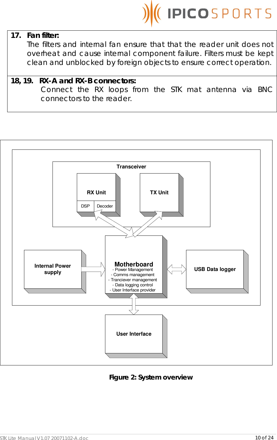
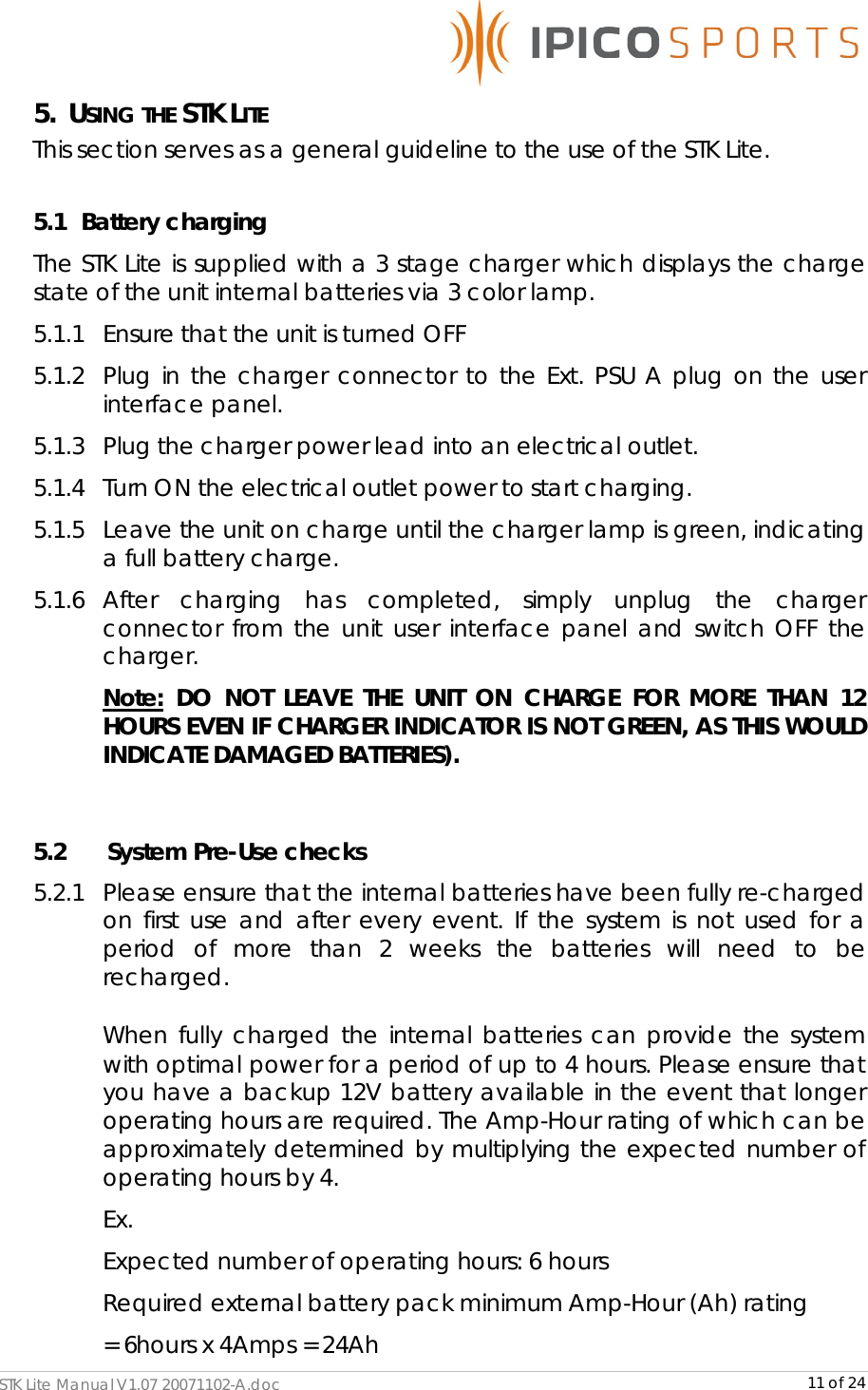
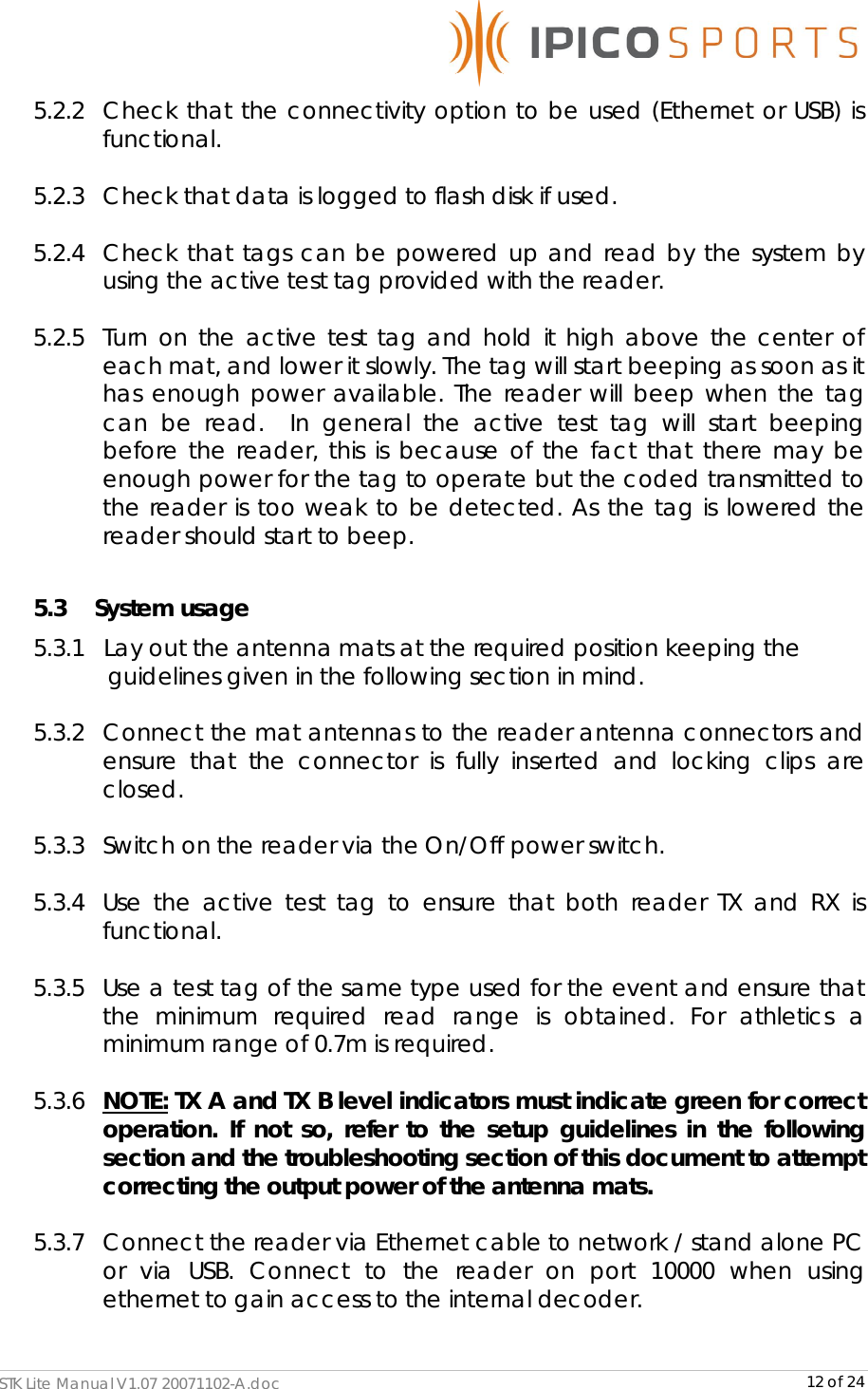
User Manual
Discussion / Help
Navigation