IPICO Australia IP3458A LOW FREQUENCY SPORTS TIMING SYSTEM User Manual STK Lite Manual V1 07 20071102 A
IPICO Australia LOW FREQUENCY SPORTS TIMING SYSTEM STK Lite Manual V1 07 20071102 A
USERS MANUAL
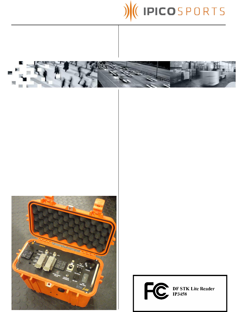
iP-X DF RFID STK Lite Reader
User Manual
Version 1.07
2 November 2007
Doc No: IP7083

STK Lite Manual V1.07 20071102-A.doc
2 of 24
Please read instructions before operating this device. This device may cause
interference with other electronic equipment that is sensitive to magnetic
radiation.
Only an authorized technician may open and work on this unit.
FCC ID: VHY-IP3458A
FCC Declaration (USA)
FCC Rules and regulations section 15.19
This device complies with Part 15 of the FCC Rules. Operation is subject to the following two
conditions: (1) this device may not cause harmful interference, and (2) this device must accept any
interference received, including interference that may cause undesired operation.
Information to user (FCC Rules and regulations section 15.21)
The user is cautioned that any changes or modifications not expressly approved by IPICO or
authorized representative could void the users authority to operate the equipment.
NOTICE
All rights reserved. No part of this document may be reproduced or transmitted in any
form or by any means without written permission from iPico Inc.
iPico Inc shall not be liable for any errors or for incidental or consequential damages in
connection with the furnishing, performance or use of this document, hardware and/or
software.
All information in this document including the design and specification are subject to
change without notice for the purpose of product improvement.
For further information contact +27 12 345-9520.
IMPORTANT
Explosive atmospheres
User shall switch off this unit and obey all safety requirements in these areas. This unit may
only be operated if the area is declared safe by a safety official. Hazardous areas
typically include fuelling areas, below decks on boats, fuel or chemical transfer/storage
points, blasting locations and areas where air contains chemical particles such as grain
dust or metal powders.
SAFETY
Avoid any extended human exposure directly in front of the reader, up to a distance of
5cm, when the unit is switched on.
Only qualified personnel may open the unit.
APPROVALS
FCC Part 15 Subpart C

STK Lite Manual V1.07 20071102-A.doc
3 of 24
TABLE OF CONTENTS
HISTORY........................................................................................................................................................................4
1. INTRODUCTION...................................................................................................................................................5
2. SYSTEM FEATURES...............................................................................................................................................5
3. SYSTEM LIMITATIONS AND STANDARDS......................................................................................................5
4. KNOW YOUR READER .......................................................................................................................................7
5. USING THE STK LITE...........................................................................................................................................11
5.1 BATTERY CHARGING..................................................................................................................................11
5.2 SYSTEM PRE-USE CHECKS ..........................................................................................................................11
5.3 SYSTEM USAGE...........................................................................................................................................12
5.4 USB DISK DATA LOGGING.........................................................................................................................13
5.5 SETTING SYSTEM DATE/TIME........................................................................................................................14
5.6 CHANGING ETHERNET CONNECTIVITY SETTINGS .......................................................................................15
5.6.2 Using MOXA Network Enabler software for Windows ......................................................15
5.6.3 Using a Telnet session...................................................................................................................18
6 ANTENNA MATS SETUP GUIDELINES............................................................................................................19
7 TROUBLESHOOTING.........................................................................................................................................22
8 TECHNICAL SPECIFICATIONS.......................................................................................................................23
9 SUPPORT..............................................................................................................................................................24
10 TECHNICAL ASSISTANCE ...............................................................................................................................24
Table Of Figures
FIGURE 1 – STK LITE READER INTERFACE PANEL .............................................................................................................7
FIGURE 2: SYSTEM OVERVIEW........................................................................................................................................10
FIGURE 3 – TYPICAL READ SETUP...................................................................................................................................19
FIGURE 4: TAG/MAT ANTENNA ORIENTATIONS.............................................................................................................20
FIGURE 5: CRITICAL BACKUP SETUP ..............................................................................................................................20
Tables
TABLE 1 : INTERFACE PANEL SUMMARY...........................................................................................................................7
TABLE 2 : TECHNICAL SPECIFICATIONS..........................................................................................................................23

STK Lite Manual V1.07 20071102-A.doc
4 of 24
HISTORY
Version Date Responsible Person Detail
1.00 20070119 R. Vergottini First Release
1.01 20070404 R. Vergottini Add detail to mat setup and
document IP number
1.02 20070513 MVD Add new faceplate detail
1.03 20070523 MVD Update faceplate detail
1.04 20070622 R. Vergottini Update faceplate and USB data
storage detail
1.05 20070705 R. Vergottini Added details to charging
section, notice of removal of
serial and PSU-B, correct TX level
indictor statement, update USB
logger operation.
1.06 20070820 R. Vergottini Change faceplate details,
remove ref. to serial and PSU-B.
1.07 20071102 R. Vergottini Add FCC documentation

STK Lite Manual V1.07 20071102-A.doc
5 of 24
1. INTRODUCTION
This manual is intended as a general guide in the setup and usage of the
STK Lite system. It must be understood that setup environment can
influence the performance of the system. This manual attempts to guide
the user into establishing a reliable setup that delivers optimum tag read
performance under most conditions.
2. SYSTEM FEATURES
• Read passive RFID tags at an average of 0.75m distance
• Continuous operation from fully charged internal batteries of up to 4
hours.
• Based on the proven iPX protocol for high speed and tag density
• Low maintenance
• Easy setup
• Easy operation
• Easy to transport
• Start/Stop pushbutton for digital marker insertion
• Water resistant and rouged
• Allows connection of backup external battery pack for prolonged
operation
• Auto-tuning of mat transmit antenna
• Ethernet and USB connectivity
• Ability to log data to USB flash memory disk
3. SYSTEM LIMITATIONS AND STANDARDS
The STK Lite was designed with small athletics events in mind and it is
recommended that for larger events the STK Elite should rather be used.
The STK Lite has the following limitations pertaining to setup and usage.
• The STK Lite may only power two timing mats, which can effectively
cover an area of no more than 4m².
• Timing accuracy is dependant on the physical layout of the timing
mats to the actual timing line or point and the average speed at
which tags move over the timing mat. The system has a time
resolution of 10ms and as such timing can be accurate to a
minimum of 10ms and 50ms average for tag travel speed of 10m/s
over a 1m wide timing area.
• With the top lid closed and locked in place the reader unit is
waterproof, once the lid is open the reader is at best splash proof.

STK Lite Manual V1.07 20071102-A.doc
6 of 24
• The STK Lite should not be operated in ambient temperatures
exceeding 40 degrees celcius.
• Use only approved external battery packs and charging units
supplied by iPico. Failure to do so may result in electric shock,
degraded performance and/or system damage.
• The STK Lite offers a raw data-stream which contains tag data as
they are read in the following format:
Byte Description Info
0 Header character 1 Frame header, ‘a’
1 Header character 2 Frame header, ‘a’
2-3 Reader ID 0-255 in ASCII hex
4-15 Tag ID MS digit first, excluding CRC
16-19 I and Q channel counter Binary counters 0-255 in ASCII hex
20 –33 Date/Time Date and time with 10ms resolution. 390ms/10 = 39 =
“27” (27 = 0x32 + 0x37) and the month 12 is 0x31+
0x32.
34-35 LRC Checksum on bytes 2 to 33
36-37 End of packet (CR, LF) 0x0d, 0x0a
Example:
Tag with an ID = 580011223344 is read at 14:05:20.39 on 2006-12-30 the data
packet received from the reader would be
aa00580011223344090006123014052027xx\r\n
where xx is the calculated LRC.
Further details can be obtained from the iPico Reader Serial Protocol
document.
STK Lite Manual V1.07 20071102-A.doc
7 of 24
4. KNOW YOUR READER
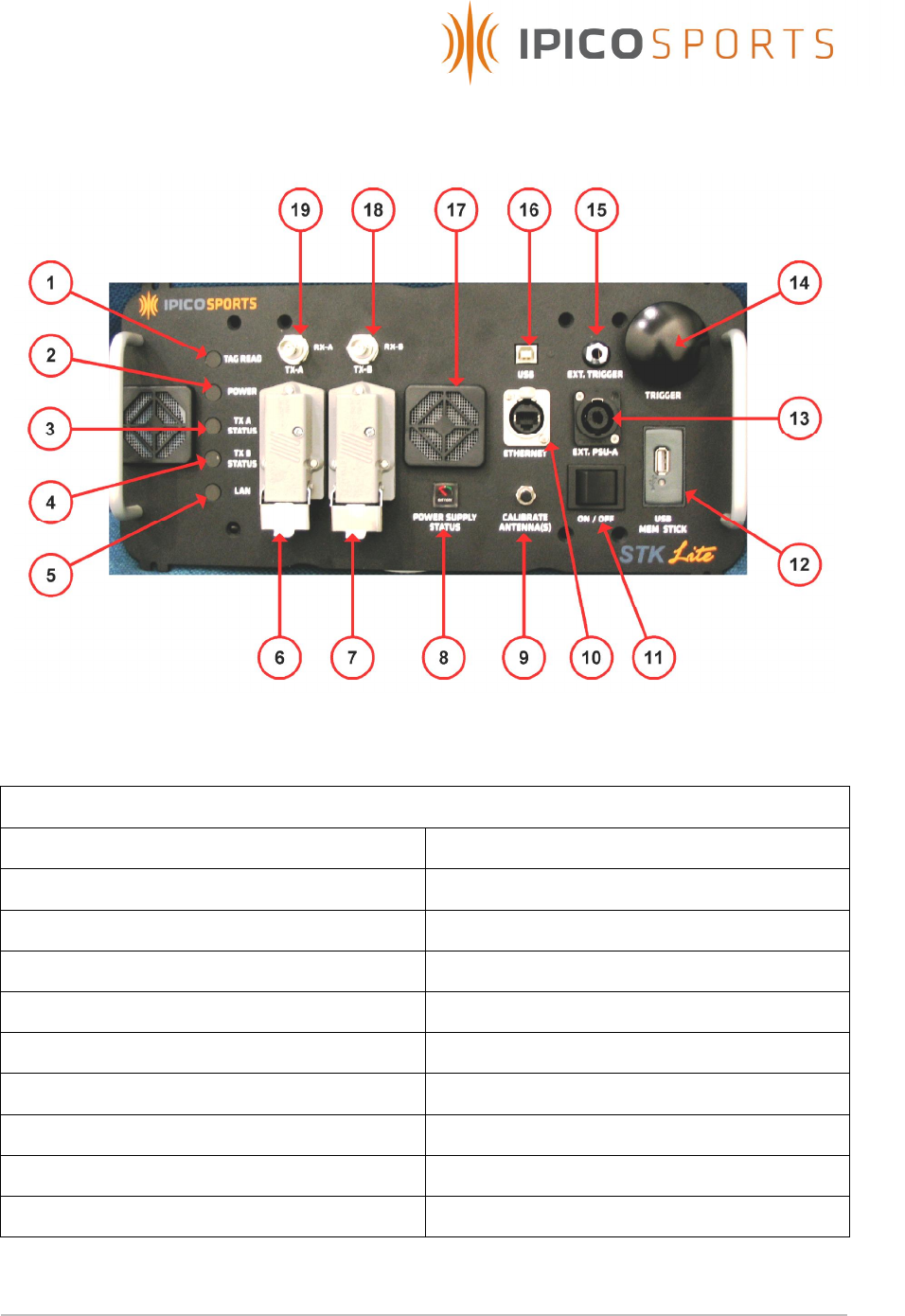
Figure 1 – STK Lite Reader Interface panel
Summary
1. Tag read indicator 11. Power ON/OFF switch
2. Power indicator 12. USB Memory stick controller
3. TX-A Level indicator 13. External power supply connector
4. TX-B Level indicator 14. Trigger button
5. LAN Activity indicator 15. External trigger connector
6. Antenna A transmitter connector 16. USB communications connector
7. Antenna B transmitter connector 17. Ventilation Fan/Filter
8. Power supply status indicator 18. Antenna B receiver connector
9. Antenna calibration button 19. Antenna A receiver connector
10.Ethernet communications connector
Table 1 : Interface panel summary

STK Lite Manual V1.07 20071102-A.doc
8 of 24
1. Tag Read Indicator:
This indicator will illuminate green each time that a tags ID has been
successfully read and the internal buzzer will sound. It also indicates
the status of the RF Transmitter and will illuminate red when for any
reason the RF transmitter is off.
2. Power Indicator:
This indicator is illuminated when the system is turned ON via the
On/Off power switch and indicates the available battery power.
Green = Battery power level high, Red = Battery power level low to
medium, indicating that the units internal batteries must be recharged
or the unit should be connected to an approved external power
supply for extended operation.
3, 4. TX-A Level and TX Level-B:
Indicates the level of output power / tuning effectiveness of the
reader channel A and B transmitters. Green = Acceptable power
output and Red = Poor power output which will result in
unacceptable read performance.
5. LAN Activity:
Indicates red when an Ethernet connection is present and flashes
green as data is exchanged with reader and connected device.
6, 7. TX-A and TX-B connectors:
Connect the reader to the TX loops of the STK mat antennas.
8. Power supply status indicator:
Rough indication of the power supply status. Range is from
approximately 10.1V – 13.8V. The reader will automatically switch off
when the power supply level reaches 10.5 Volts to prevent
permanently damaging lead acid batteries.
9. Calibrate Antenna(s) button:
This push button allows the user to initiate an automatic tuning of the
TX loop antennas. This feature can be useful in the event where mats
are moved or external environment changes rapidly but there is not
enough time to wait for an automatic tune event to take place.

STK Lite Manual V1.07 20071102-A.doc
9 of 24
10. Ethernet connector:
Ethernet connection to the reader’s data port. Default IP address =
192.168.1.32 : port 10000. IP address can be changed using telnet or
the MOXA network enabler administrator tool (See section 5.5).
11. ON/OFF switch:
Power switch.
12. USB Memory Stick:
Used to dynamically store race data on a 1Gbyte USB 2.0 memory
stick. Stop of data logging controlled via the Trigger button
(see section 5.3).
13. Ext. PSU-A connector:
This is to connect external battery whilst the unit is operational or a
battery charger to the unit when not operational and the power
switch is OFF.
14. Trigger button:
This allows the user to insert a digital marker into the data-stream and
to initiate or finalize logging of data to a USB flash disk.
When a USB flash disk is inserted the unit will be automatically
initialized which will be indicated by a two audible beeps. Data
logging can then be stopped by holding down the button until the
buzzer sounds 5 times, indicating finalization of data logging.
(Data logging must be finalized as described above to prevent lost
and/or corrupt data !).
The digital marker can indicate the start/stop of an event. This trigger
can also be used to manually mark the time that a runner passes
over the timing mats. This will ensure a correct count of the actual
number of runners who passed over the timing mats in case of
suspected tag failures or runners who have lost their tags etc.
(see section 5.3).
15. Ext. Trigger:
This input can be used to connect an external trigger source to the
reader i.e. remote Start gun button.
16. USB connector:
USB connection to the reader’s data port via a CP210x device driver
at a default baud rate of 38400.
STK Lite Manual V1.07 20071102-A.doc
10 of 24
17. Fan filter:
The filters and internal fan ensure that that the reader unit does not
overheat and cause internal component failure. Filters must be kept
clean and unblocked by foreign objects to ensure correct operation.
18, 19. RX-A and RX-B connectors:
Connect the RX loops from the STK mat antenna via BNC
connectors to the reader.
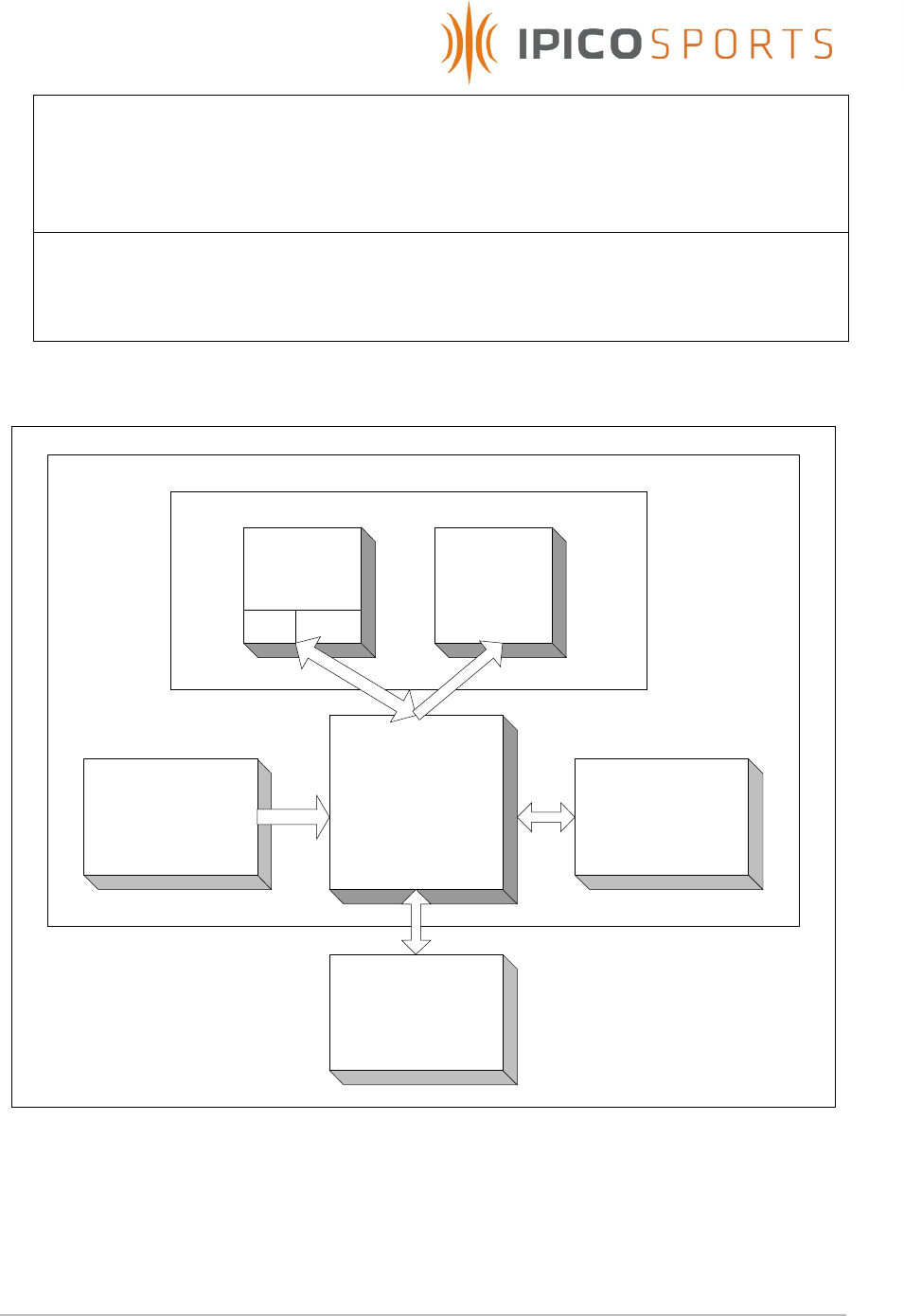
Motherboard
- Power Management
- Comms management
- Tranciever management
- Data logging control
- User Interface provider
Transceiver
TX UnitRX Unit
DSP Decoder
Internal Power
supply
User Interface
USB Data logger
Figure 2: System overview

STK Lite Manual V1.07 20071102-A.doc
11 of 24
5. USING THE STK LITE
This section serves as a general guideline to the use of the STK Lite.
5.1 Battery charging
The STK Lite is supplied with a 3 stage charger which displays the charge
state of the unit internal batteries via 3 color lamp.
5.1.1 Ensure that the unit is turned OFF
5.1.2 Plug in the charger connector to the Ext. PSU A plug on the user
interface panel.
5.1.3 Plug the charger power lead into an electrical outlet.
5.1.4 Turn ON the electrical outlet power to start charging.
5.1.5 Leave the unit on charge until the charger lamp is green, indicating
a full battery charge.
5.1.6 After charging has completed, simply unplug the charger
connector from the unit user interface panel and switch OFF the
charger.
Note: DO NOT LEAVE THE UNIT ON CHARGE FOR MORE THAN 12
HOURS EVEN IF CHARGER INDICATOR IS NOT GREEN, AS THIS WOULD
INDICATE DAMAGED BATTERIES).
5.2 System Pre-Use checks
5.2.1 Please ensure that the internal batteries have been fully re-charged
on first use and after every event. If the system is not used for a
period of more than 2 weeks the batteries will need to be
recharged.
When fully charged the internal batteries can provide the system
with optimal power for a period of up to 4 hours. Please ensure that
you have a backup 12V battery available in the event that longer
operating hours are required. The Amp-Hour rating of which can be
approximately determined by multiplying the expected number of
operating hours by 4.
Ex.
Expected number of operating hours: 6 hours
Required external battery pack minimum Amp-Hour (Ah) rating
= 6hours x 4Amps = 24Ah

STK Lite Manual V1.07 20071102-A.doc
12 of 24
5.2.2 Check that the connectivity option to be used (Ethernet or USB) is
functional.
5.2.3 Check that data is logged to flash disk if used.
5.2.4 Check that tags can be powered up and read by the system by
using the active test tag provided with the reader.
5.2.5 Turn on the active test tag and hold it high above the center of
each mat, and lower it slowly. The tag will start beeping as soon as it
has enough power available. The reader will beep when the tag
can be read. In general the active test tag will start beeping
before the reader, this is because of the fact that there may be
enough power for the tag to operate but the coded transmitted to
the reader is too weak to be detected. As the tag is lowered the
reader should start to beep.
5.3 System usage
5.3.1 Lay out the antenna mats at the required position keeping the
guidelines given in the following section in mind.
5.3.2 Connect the mat antennas to the reader antenna connectors and
ensure that the connector is fully inserted and locking clips are
closed.
5.3.3 Switch on the reader via the On/Off power switch.
5.3.4 Use the active test tag to ensure that both reader TX and RX is
functional.
5.3.5 Use a test tag of the same type used for the event and ensure that
the minimum required read range is obtained. For athletics a
minimum range of 0.7m is required.
5.3.6 NOTE: TX A and TX B level indicators must indicate green for correct
operation. If not so, refer to the setup guidelines in the following
section and the troubleshooting section of this document to attempt
correcting the output power of the antenna mats.
5.3.7 Connect the reader via Ethernet cable to network / stand alone PC
or via USB. Connect to the reader on port 10000 when using
ethernet to gain access to the internal decoder.

STK Lite Manual V1.07 20071102-A.doc
13 of 24
5.3.8 Set the current date/time accordingly. (See section 5.4).
5.4 USB disk data logging
5.4.2 With the system powered ON and fully operational, insert the USB
flash disk drive into the USB Stick data logger.
5.4.3 The reader will automatically start logging data as soon as a
logging file has been successfully created. (Two beeps will be heard
when this step has been successful)
5.4.4 Once data logging is completed, press and hold the Trigger button
until five audible beeps are generated by the reader, and the USB
stick activity light has settled to a steady state indication. It is now
safe to remove the USB flash disk memory stick.
5.4.5 Data logging has now been finalized, and the logged data stored
into a file named TAGDATA.LOG in the root directory of the USB
flash disk memory stick.
5.4.6 Data is stored as normal ASCII text, which can be viewed by any
text editor such as Microsoft Windows NotePad, WordPad or
Microsoft Office Word etc. under the Windows operating system
platform.
5.4.7 NOTE: Previous logged data will not be erased. Instead new data
will be appended to the bottom of the existing log file incase the log
file has not been deleted before logging is started.

STK Lite Manual V1.07 20071102-A.doc
14 of 24
5.5 Setting system date/time
To set the date/time of the system, a specific system message
containing the date and time to be set must be sent from a PC to
the system which has the following format,
Hdr ID Len Cmd
Date Day
Time
y
y
m
m
d
d
n
n
h
h
m
m
s s <CR>
<LF>
a
c
0
0
0
7
0 1 0
1
0 2 1
0
0
4
2
2
1 5 2
3
\r \n
= ac00070101021004221523\r\n
where the variables of date, day and time are to be adjusted to
the date/time to be set.
In the above example the date/time to set will thus be: 2001/02/10,
4th day of week(Thursday), 22:15:23 p.m.
Acknowledgement from system:
Hdr ID Len Cmd LRC <CR>
<LF>
a b 0 0 0 0 0 1 2 1 \r \n
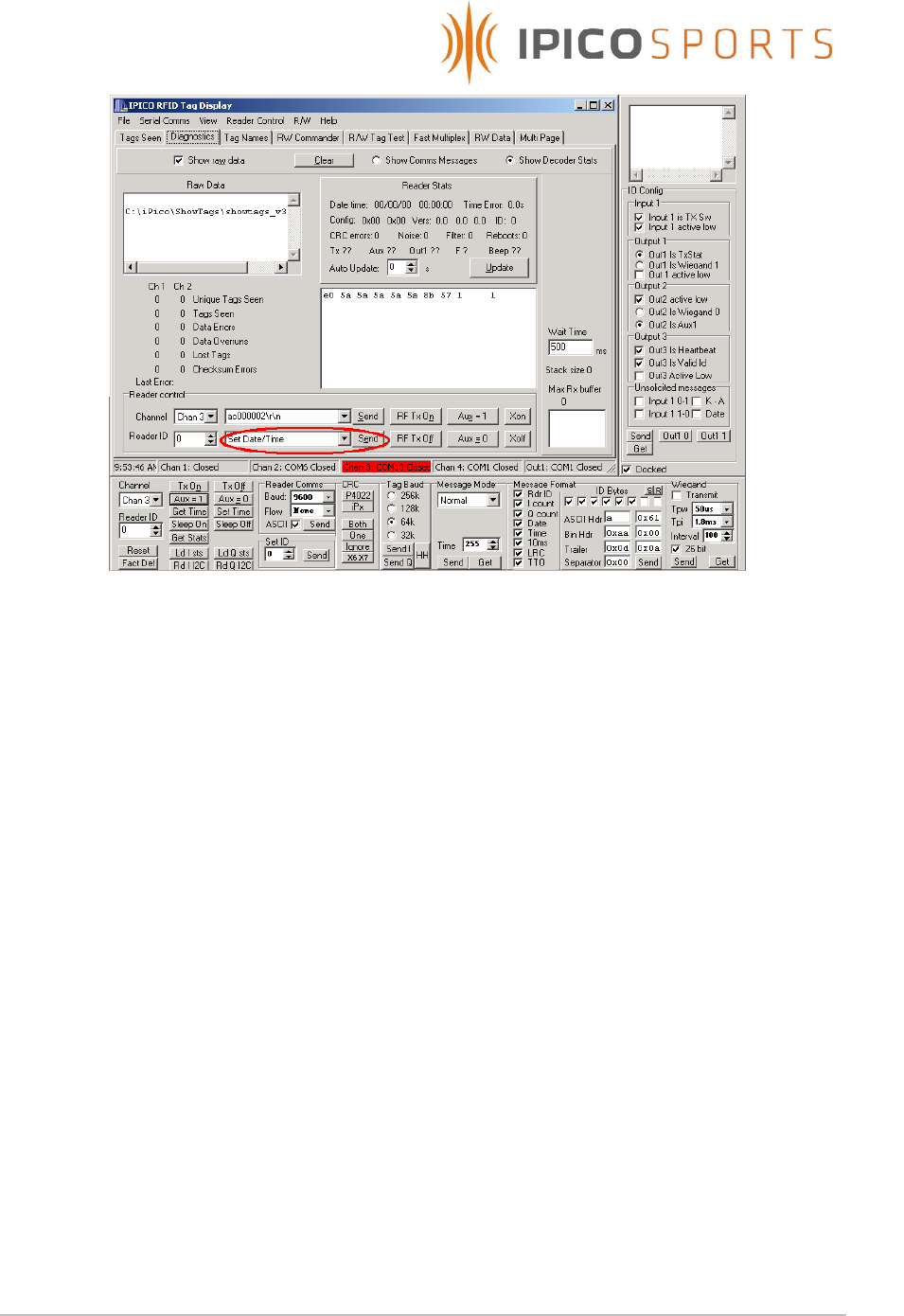
To setup the date/time of the system to be exactly equal to the PC
to which the unit is connected, the iPico freeware program
ShowTags which is supplied on the CD which accompanies the unit
can be used.
STK Lite Manual V1.07 20071102-A.doc
15 of 24
By connecting to the unit over either USB or Ethernet, and sending
the Set Date/Time command as shown in the figure above, the units
time will be set equal to the PC to which the unit is connected.
For more information please view the ShowTags User Manual,
supplied on the accompanying CD.
5.6 Changing Ethernet connectivity settings
5.6.2 Using MOXA Network Enabler software for Windows
1. Please install the MOXA Network Enabler Administrator software
package by running setup.exe found on the STK Lite software
CD, under the MOXA SDK directory.
2. Ensure that the reader is connected via straight through cable to
a network access point / hub and that your PC is connected to
the same network. If you are connecting directly to the reader,
use a cross over Ethernet cable and change your Windows
Network TCP/IP settings to match the subnet of the reader.
STK Lite Manual V1.07 20071102-A.doc
16 of 24
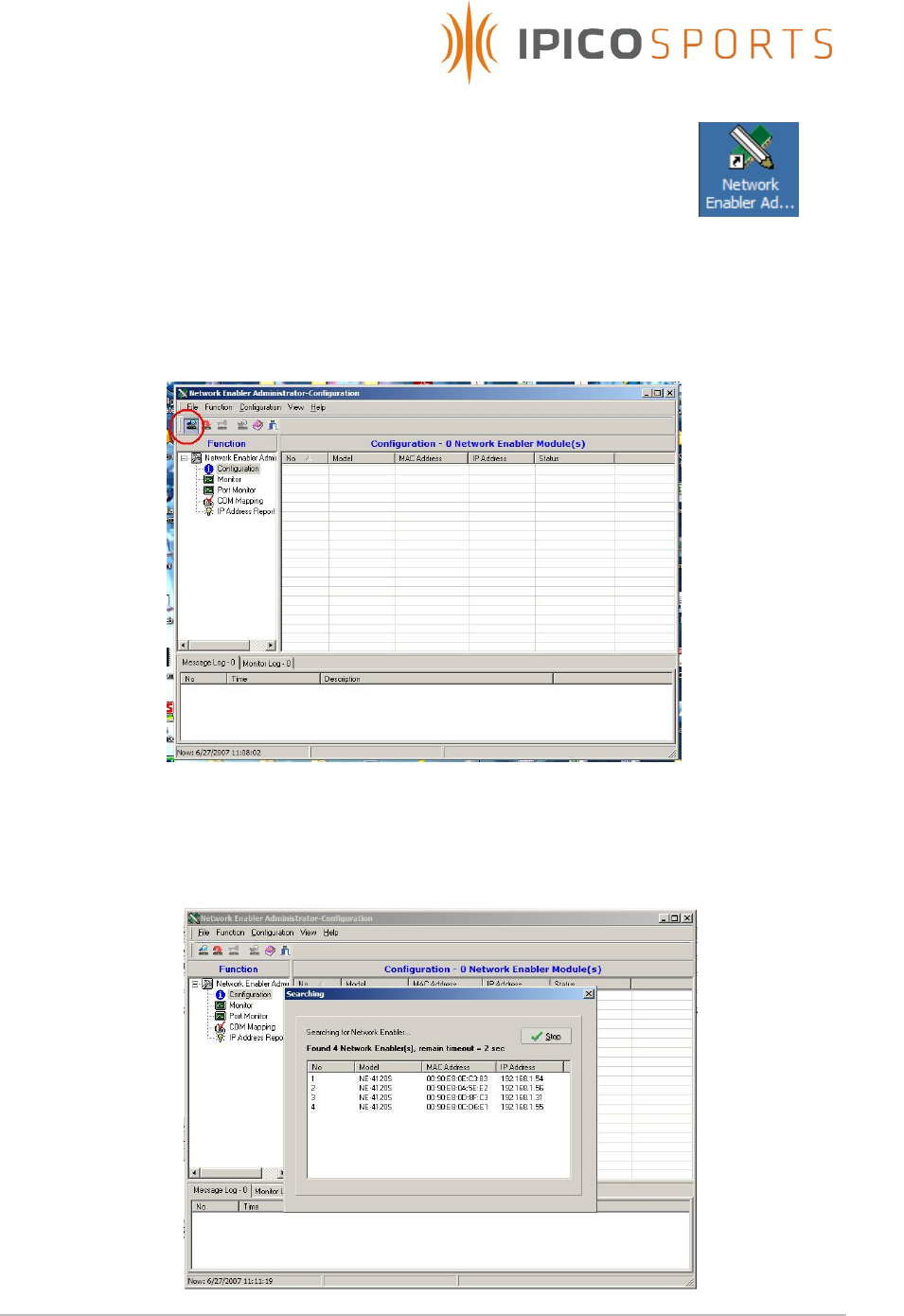
3. Start the MOXA Network Enabler Administrator software
package by clicking the icon on your desktop , or
Selecting from the Start Menu in Windows XP, : Start -> All
Programs -> Network Enabler Administrator -> Network Enabler
Administrator.
4. Start a broadcast search by selecting the icon as indicated by
the red circle in the top left hand corner in the figure below
5. After clicking the broadcast search button, A window which
times out automatically will appear which will look similar to the
figure below.
STK Lite Manual V1.07 20071102-A.doc
17 of 24
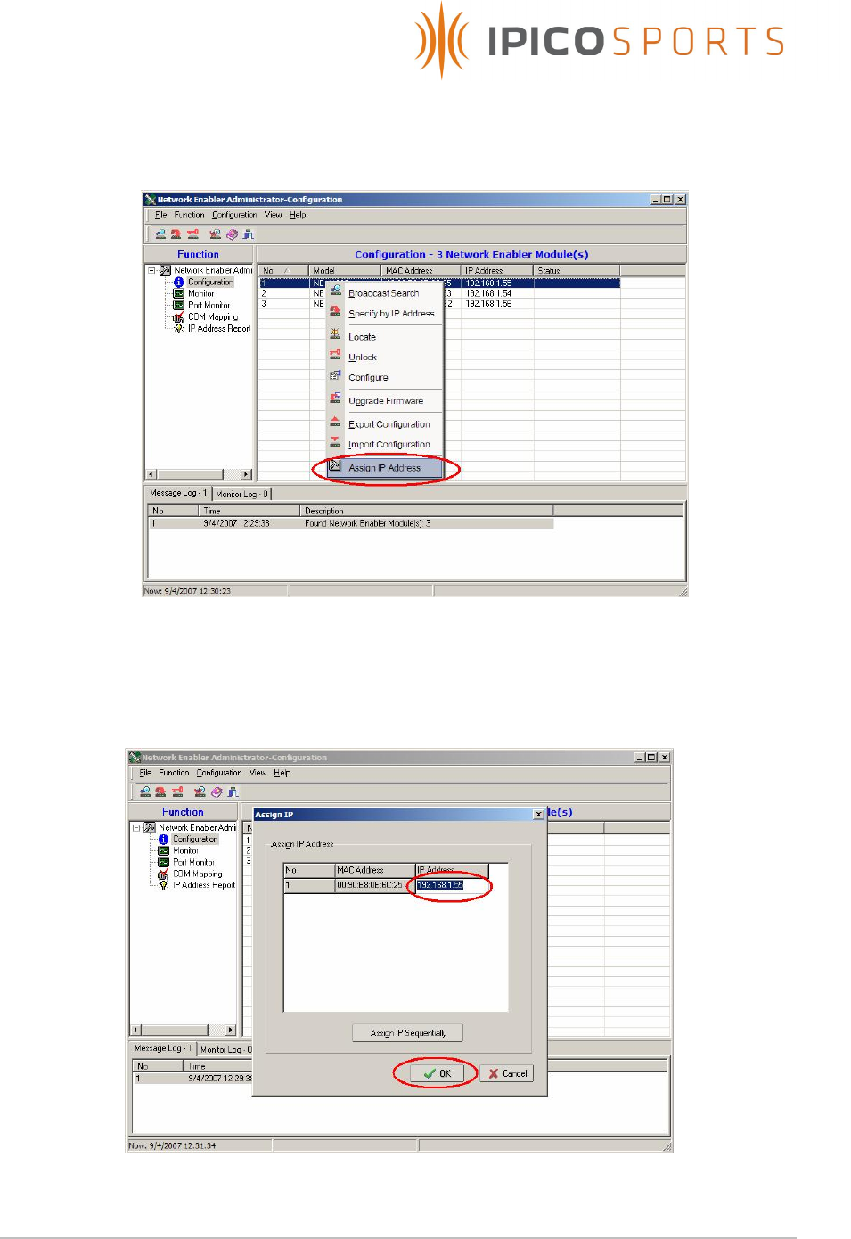
6. Right click on the device in the list to open a drop down menu,
and select Assign IP Address as shown in the figure below.
7. In the window that appears, enter the new IP address to be set,
and select OK as shown in the figure below.

STK Lite Manual V1.07 20071102-A.doc
18 of 24
5.6.3 Using a Telnet session
1. From a command shell or the Windows Run box, connect to the
system using Telnet with the default Telnet port.
Type in telnet proceeded with the system IP address to connect
to the Moxa console configuration.
Ex. telnet 192.168.1.32
2. Type 2 to select Network Settings, and press Enter.
3. Type 1 to select IP Address, and press Enter.
4. Use the Backspace key to erase the current IP address, type in
the new IP Address and then press Enter.
STK Lite Manual V1.07 20071102-A.doc
19 of 24
6 ANTENNA MATS SETUP GUIDELINES
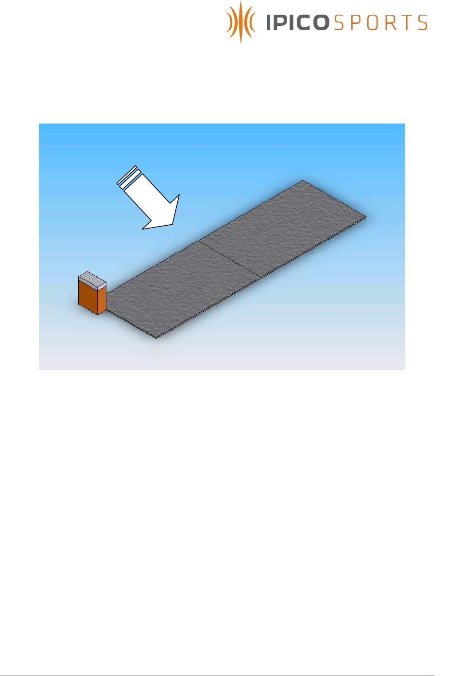
Figure 3 below illustrates a typical read setup.
Figure 3 – Typical read setup
6.1 Timing mats are to placed at least 0.5m from any large metal /
conducting objects such as fences, barb wire etc.
6.2 The STK Lite reader and mats are to placed at a distance of at least 10m
from other electromagnetic field generating equipment such as fan
motors, audio equipment etc.
6.3 No AC power lines including extension cords should be placed at a
distance of less than 1m from the reader unit and timing mats.
6.4 Ensure that mats are lain out in there full length and breadth and not
rolled up or folded when being used as this could prevent the mats from
operating at maximum efficiency due to incorrect tuning.
6.5 When laying mats out, overlap the edges of the two mats such that the
wires within the mats are directly over each other.
6.6 Run the lead of the furthest mat through the centre of other mats to the
reader, and never down the side edges of the mats.
Tag
travel
direction
STK Lite Manual V1.07 20071102-A.doc
20 of 24
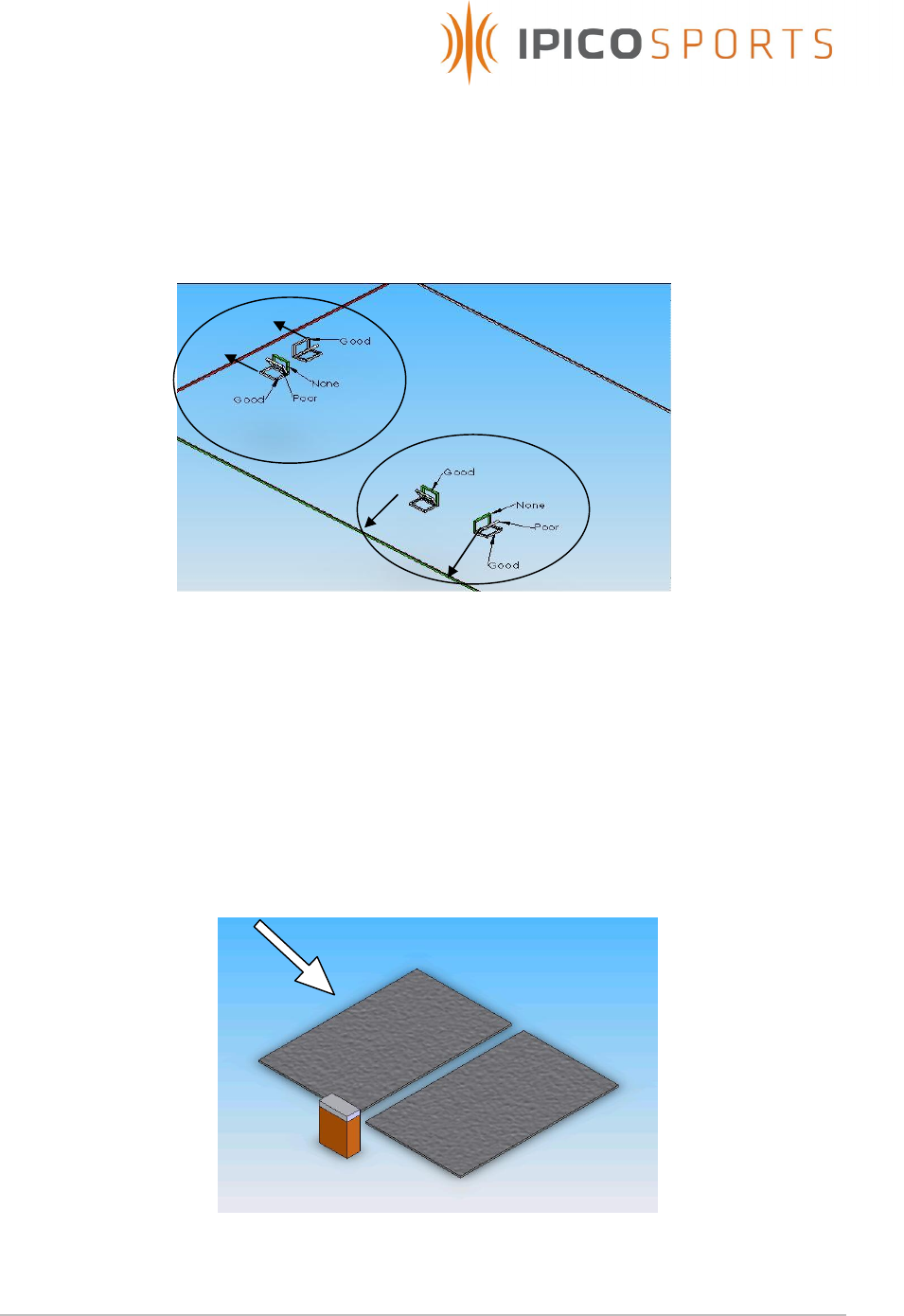
6.7 Always keep the tag orientation to the timing mat antenna in mind.
Maximum coupling and thus read range occurs when the magnetic flux
lines of the two loops pass through each other. Figure 4 below illustrates
typical tag and mat antenna orientations with indications as to where
good and poor coupling take place.
Figure 4: Tag/Mat antenna orientations
6.8 When it is critical that all tags be read and the environment is of such
nature that effective read range cannot be obtained due to tuning
limitations it is advised to place one timing mat behind the other
effectively forming a second loop on which the same tag can be read.
The backup mat format has proved so essential that this kind of setup is
preferred under most conditions and is also used by competing RFID
time keeping systems. Figure 5 below illustrates a typical setup of this
format.
Figure 5: Critical backup setup

STK Lite Manual V1.07 20071102-A.doc
21 of 24
6.9 When using multiple readers to cover an extended area the following
layout is advised.
6.10 When using multiple readers to cover an extended area, and the
backup mat format is required the following layout is advised.
Mat
connected
to TX-A of
reader 1
Mat
connected
to TX-B of
reader 1
Mat
connected
to TX-A of
reader 2
Mat
connected
to TX-B of
reader 2
Mat
connected
to TX-A of
reader n
Mat
connected
to TX-B of
reader n
Mat
connected
to TX-A of
reader 1
Mat
connected
to TX-B of
reader 2
Mat
connected
to TX-A of
reader 3
Mat
connected
to TX-B of
reader 4
Mat
connected
to TX-A of
reader 5
Mat
connected
to TX-B of
reader n
Mat
connected
to TX-B of
reader 1
Mat
connected
to TX-A of
reader 2
Mat
connected
to TX-B of
reader 3
Mat
connected
to TX-A of
reader 4
Mat
connected
to TX-B of
reader 5
Mat
connected
to TX-A of
reader n

STK Lite Manual V1.07 20071102-A.doc
22 of 24
7 TROUBLESHOOTING
7.1 The minimum required read range is not obtained
Press and hold the Calibrate antennas pushbutton and test the read
range once more. If the read range has not improved it may be that the
environment is of such nature that an optimal tune cannot be obtained.
Move the antennas to a new location and determine whether read range
improves. Also make sure to follow the setup guidelines given in the
previous section.
7.2 TX Output indicates acceptable power output but tag cannot be read
It is possible that the RX channel is faulty, antenna not connected or
environment noise too high to read the tag.
7.3 TX Level indicator stays red
Environment around antenna mats do not allow for optimal output power
tuning, transmitter output faulty, antenna not connected or TX output set
to OFF via software.
7.4 Reader buzzer sounds when reading tag but no data received via
Ethernet or USB connection
Possible causes are: Faulty Ethernet module, Faulty USB module, cable
damaged or not connected or incorrect reader hardware (serial to
Ethernet converter) setup or incorrect USB serial baud setting.
7.5 Reader not functional ( Power indicator not functional )
Possible causes are: Depleted internal batteries, Power switch not turned
ON or faulty reader.

STK Lite Manual V1.07 20071102-A.doc
23 of 24
8 TECHNICAL SPECIFICATIONS
Power supply 12VDC @ 4A avg. consumption
Internal supply: 12V DC (2x7Ah) batteries
External supply: 12V DC Charger
Transmitter power 250V Pk-Pk @ 100% duty cycle
Operating frequency TX @ 125kHz & 127kHz
RX @ 6.8MHz
Antenna type Externally connected, matched to 50Ohm (Electrical/Physical
configuration to comply with ETSI and FCC). Typical antenna
used is the STK timing 2m x 1m antenna mat lying flat on
ground.
Read range Dependant on reader antenna, tag and environment.
Typical read ranges using half credit card size STK shoe tags
are 0.6m to 1.5m
Communication Reader/Host: USB and Ethernet
Reader/Tag: IP-X Read Only
Data storage External USB flash disk. Recommended USB 2.0 compliant with
size 256Mb to 1Gb. (Disk not included)
Electrical Interface TX: Hirschmann ST series 3 pole connector
RX: BNC
External charge/Power: Neutrik 4 pole audio connector
Environmental IP65 with Lid closed.
High impact glass filled Nylon enclosure.
Physical 440 x 220 x 340 mm
Weight un-packed: 12.0 kg without antennas
Accessories External charge/battery lead with Neutrik Connector, and
Ethernet cable hood
Table 2 : Technical specifications

STK Lite Manual V1.07 20071102-A.doc
24 of 24
9 SUPPORT
Ordering Info:
IP Number Product Code Description
IP3458 iP-X DFRDR-LR-STK-LI-RO DF Long Range STK Lite
Reader Read Only
IP0903 12V DC 4A Battery
Charger
IP2227 5m CAT5 Ethenet patch
lead
IP0823 1.8m USB 2.0 patch lead
IP2226 1m External PSU
connection cable.
IP0824 12V DC 7AH CSB
GP1272 battery
10 TECHNICAL ASSISTANCE
iPico Sports online: http://www.ipicosports.com
iPico Inc online: http://www.ipico.com