IR TEC GC171910 Motion Detector User Manual
Ir Tec International Ltd Motion Detector
UserManual.wiki
>
IR TEC
>
GC171910 User Manual
>
Manual DP 550
Contents
1.
Manual DP 250
2.
Manual DP 550
3.
Manual DP 550P
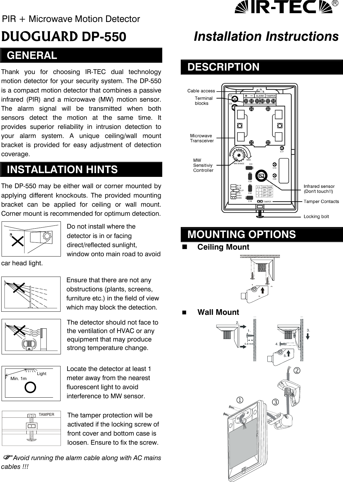
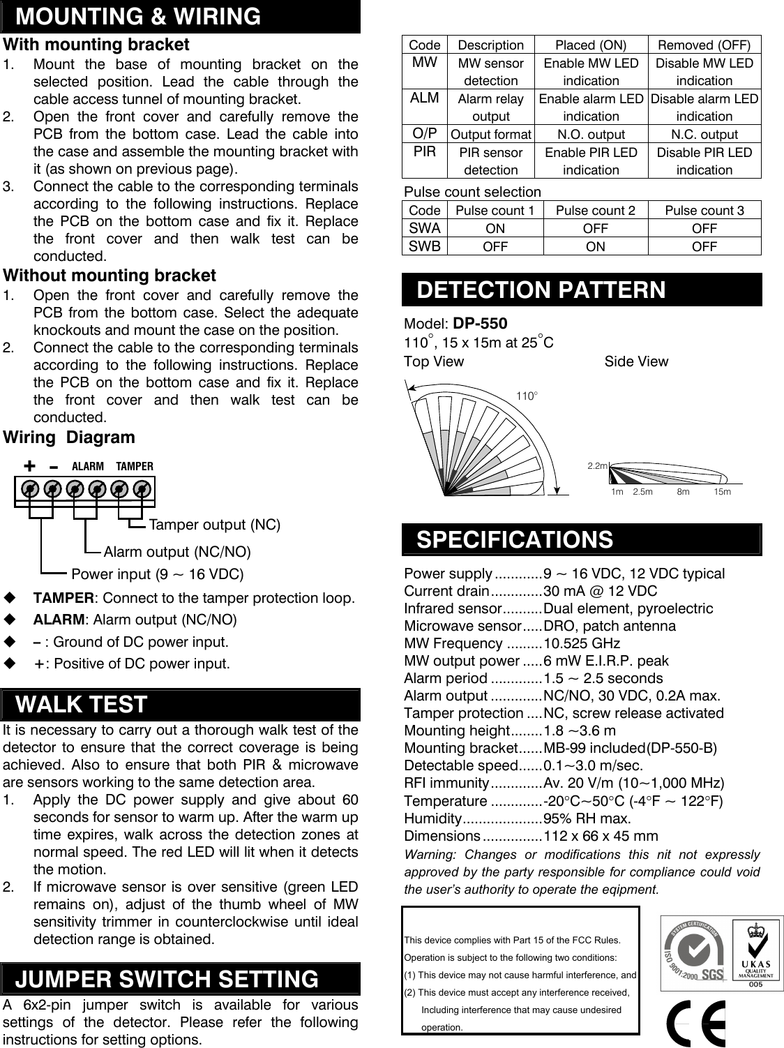
Manual DP 550
Navigation menu
Upload a User Manual
Namespaces
Wiki Guide
HTML
PDF
Info
Views
User Manual
Discussion / Help
Navigation