IR TEC HS150900 Occupancy Sensor User Manual IM EN LMS 509
IR-TEC International Ltd. Occupancy Sensor IM EN LMS 509
IR TEC >
User Manual
Risque de choc électrique -Débranchez l'alimentation avant
l'entretien.
Ouvrir Type commutateurs optoélectroniques.
Risk of Electric Shock - Disconnect power supply before
servicing.
Open Type Photoelectric Switches.
WARNING & CAUTION
Federal Communication Commission Interference Statement
AVERTISSEMENT & PRUDENCE
OVERVIEW
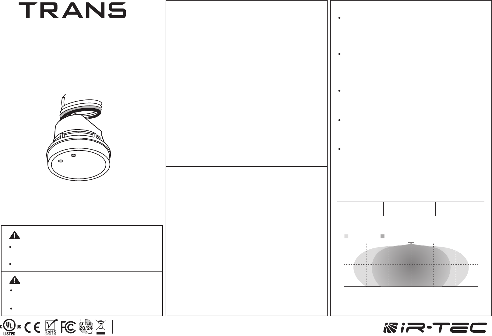
The LMS-509 series member of the TRANS family is a line
voltage occupancy sensor designed for all-purposes energy
efficient lighting control. This occupancy sensor employs an
advanced High Frequency Doppler (HFD) sensing technology
to provide superior sensing performance of minor motions,
such as typing, writing, or reading. The HFD technology is
operating with high frequency radio waves which are capable of
detecting the occupant's presence and movements without
requiring unobstructed line-of-sight like PIR sensor.
The Accu-Set digitalized potentiometers make the sensor
setting easier, faster and more accurate than the conventional
analog ones. 4 levels of sensitivity can be selected via DIP
switch setting to provide different coverage. An exclusive Hybrid
Switching technology makes LMS-509 series perfect to control
the lighting with exceptionally high inrush current (HIC) while
switching on, such as multiple LED or CFL lightings connected
in parallel. The sensor comes with ambient light sensor (ALS) to
inhibit switching on the light if the ambient light level is higher
than the threshold set. Like all sensors in the TRANS family, the
LMS-509 series is also available in various mounting options.
APPLICATION NOTES
DETECTION PATTERN
Avoid placing the sensor in an area surrounded with
metallic wall which may block or absorb the radio
wave. If possible, place the sensor to the opening
as close as possible.
Fluorescent light may cause interference to the HFD
sensor operation, and result in lighting permanent
on. If possible, avoid placing the HFD sensor within
1m (3ft.) of fluorescent light.
Avoid sensor placement facing doors, corridors or
exits as HFD sensor may detect the traffics at
adjacent area.
HFD sensors are best for use in areas with partitions
and high dividers, or high level of minor motion
activities.
The HFD sensor is more sensitive to the movements
“toward” than “across” the sensor, so ensure to
place the sensor at the position “toward” the
movements of occupant.
P/N: 058-50904-004 Printed in Taiwanwww.irtec.com
This product may be covered by one or more U.S. patents or patent applications.
Please visit www.irtec.com for more information.
Line Voltage Occupancy Sensor
LMS-509 series
INSTALLATION INSTRUCTIONS
20 302030 10 30
6 969 3 30
0
3
6
0
10
20
(ft)
(ft)
(m)
(m) Minor motionMajor motion
Mounting Height
Coverage*
3 m (10 ft)
180 m2 (2,000 ft2)
6 m (20 ft)
100 m2 (1,200 ft2)
*Sensitivity 100%
This device complies with Part 15 of the FCC Rules. Operation is subject to the
following two conditions: (1) This device may not cause harmful interference, and
(2) this device must accept any interference received, including interference that
may cause undesired operation.
This equipment has been tested and found to comply with the limits for a Class B
digital device, pursuant to Part 15 of the FCC Rules. These limits are designed to
provide reasonable protection against harmful interference in a residential
installation. This equipment generates, uses and can radiate radio frequency
energy and, if not installed and used in accordance with the instructions, may
cause harmful interference to radio communications. However, there is no
guarantee that interference will not occur in a particular installation. If this
equipment does cause harmful interference to radio or television reception, which
can be determined by turning the equipment off and on, the user is encouraged
to try to correct the interference by one of the following measures:
-Reorient or relocate the receiving antenna.
-Increase the separation between the equipment and receiver.
-Connect the equipment into an outlet on a circuit different from that to which
the receiver is connected.
-Consult the dealer or an experienced radio/TV technician for help.
FCC Caution: Any changes or modifications not expressly approved by the party
responsible for compliance could void the user's authority to operate this
equipment.
This transmitter must not be co-located or operating in conjunction with any other
antenna or transmitter.
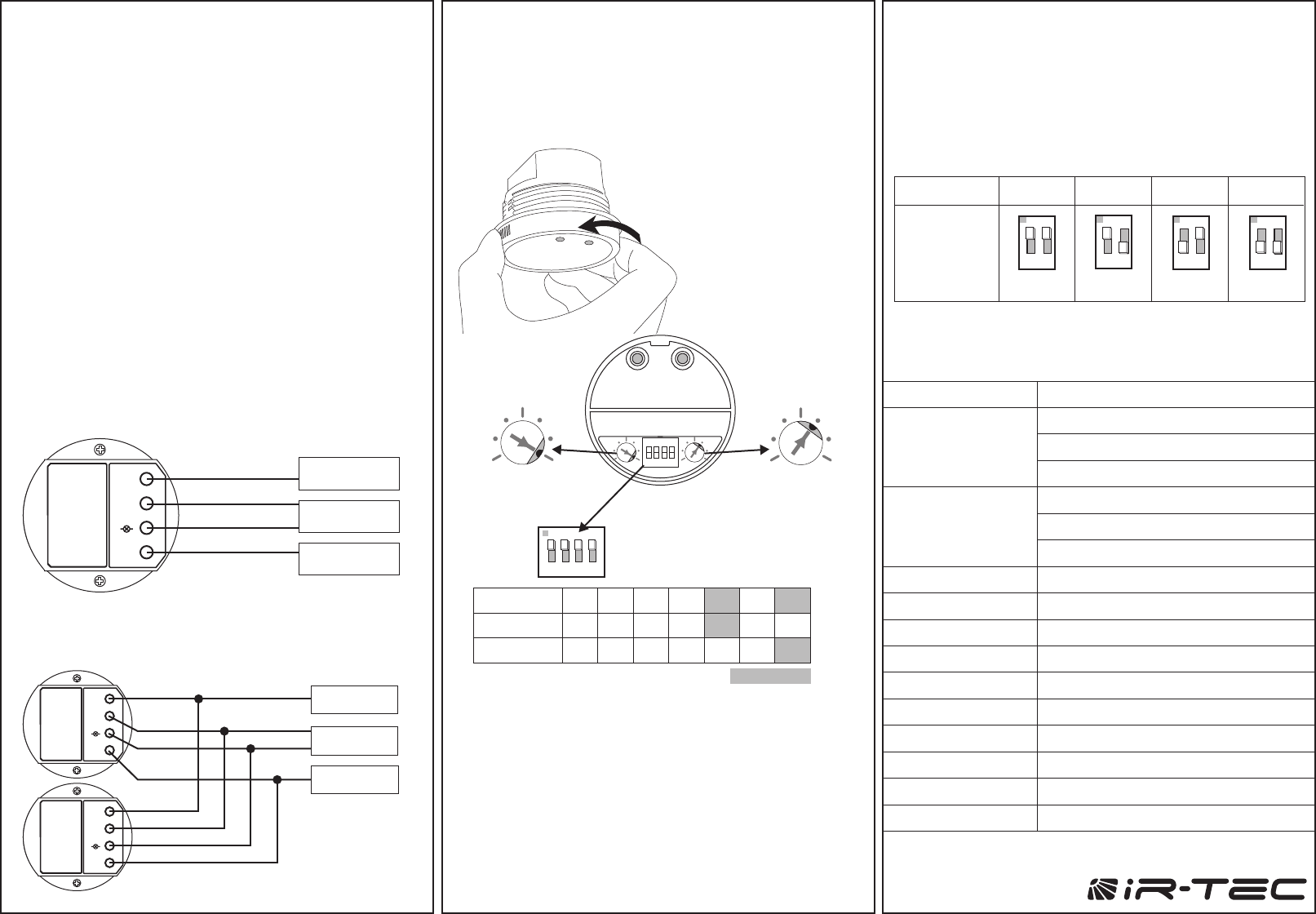
WIRING DIAGRAM
SPECIFICATIONS
www.irtec.com
The potentiometer T sets the period of delay time that sensor
will turn off the connected lights after the area is vacated.
The LMS-509 series can be mounted with a junction box
into the ceiling, internally integrated or externally attached
to a fixture to control the lighting with specific mounting
bracket. Please refer to the mounting instructions
separately attached for details of mounting options
available.
The LMS-509S is an occupancy sensor designed to provide
switched line voltage power to switch on the controlled
lighting when it detects the presence of occupant. The
sensor will automatically turn off the light after the area is no
longer occupied for a period of time. An ambient light
sensor (ALS) is built-in to inhibit switching on the light if
daylighting level is higher than the threshold set.
T - Delay Time
The potentiometer L sets the ambient light level that the
sensor will activate occupancy sensing control.
*T=10 seconds shorten delay for testing convenience. The
sensor will automatically resume to the factory default delay
setting after 10 minutes, if the potentiometer has not been
adjusted to other position.
NOTE: DIP switch #3 and #4 are not functional for LMS-509S.
L - Ambient Light Level
The sensitivity and detection pattern of HFD sensor
may vary with the furniture placement, partition layout,
wall material, and shape of the space. For example, the
detection pattern will become long rectangular if sensor is
placed in a long corridor. 4 levels of sensitivity can be set
via combinations of DIP switch #1 and #2.
Sensitivity
OPERATION
The LMS-509 provides 7 different light-Off delay time and
daylight threshold settings via 2 potentiometers marked T
and L respectively. 4 levels of sensitivity can be set via
combination DIP switch #1 and #2.
To change the sensor
setting, rotate the front
cover counter-clockwise
to remove. Replace the
front cover after the
setting complete.
SENSOR SETTINGS
24H
T* 1’ 3’ 5’ 10’ 20’ 30’
T (min.)
L (lux)
1
1
2
345
6
7 1
2
345
6
7
2
3
4567
Position
15 20
510
25 60
Power supply
HFD sensitivity
Load switching
HIC protection
Detection range
Mounting height
Ambient light level
Delay time setting
Op. humidity
Op. temperature
Dimensions
120/230/277VAC
Incandescent/Halogen – 800/1200W(VA)@120/277V
Fluorescent Ballast/CFL – 800/1200W(VA)@120/277V
Ballast Electronic (LED) – 540/1200VA@120/277V
Incandescent/Halogen – 500/750W(VA)@120/277V
Fluorescent Ballast/CFL – 500/750W(VA)@120/277V
Ballast Electronic (LED) – 500/750VA@120/277V
25/50/75/100% selectable via DIP switch setting
Zero-cross Hybrid-Switching
Max. 80A for 16.7msec.
Up to 180 sq. m @ 3 m (2,000 sq. ft. @ 10 ft)
2.4 ~ 6 m (8 ~ 20 ft)
7 level Accu-Set digital potentiometer
T/1'/3'/5'/10'/20'/30' , T=10 sec. for testing
Max. 95% RH
-40°C~70°C (-40°F~158°F)
Ø60 x H42mm (2.36"x H1.65")
Maximum Load
@ -40°C~55°C
(-40°F~131°F)
Maximum Load
@ 55°C~70°C
(131°F~158°F)
Factory Set
A. Single sensor control
B. Multiple sensors control
LMS-509
NL N
Load
Line
Neutral
White
White
Red
Black
DIP switch
setting
Sensitivity 100%
ON-ON ON-OFF OFF-ON OFF-OFF
ON
1 2
75%
ON
1 2
50%
ON
1 2
25%
ON
1 2
TL
TL
(Factory set) (10 minutes)(ALS disabled)
(Factory set)
SW1 & 2 (100% Sensitivity)
SW3 & 4 (No Function)
ON
1 2 3 4
Click!
LMS-509
NL N
LMS-509
NL N
Line
Neutral
Load
White
White
Red
Black
White
White
Red
Black