ITM TPMA111 4 Wires Analog Resistive Touch Screen User Manual
ITM INC 4 Wires Analog Resistive Touch Screen
UserManual.wiki
>
ITM
>
TPMA111 User Manual
User Manual
Navigation menu
Upload a User Manual
Namespaces
Wiki Guide
HTML
PDF
Info
Views
User Manual
Discussion / Help
Navigation
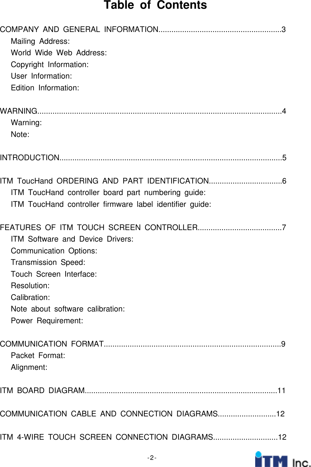
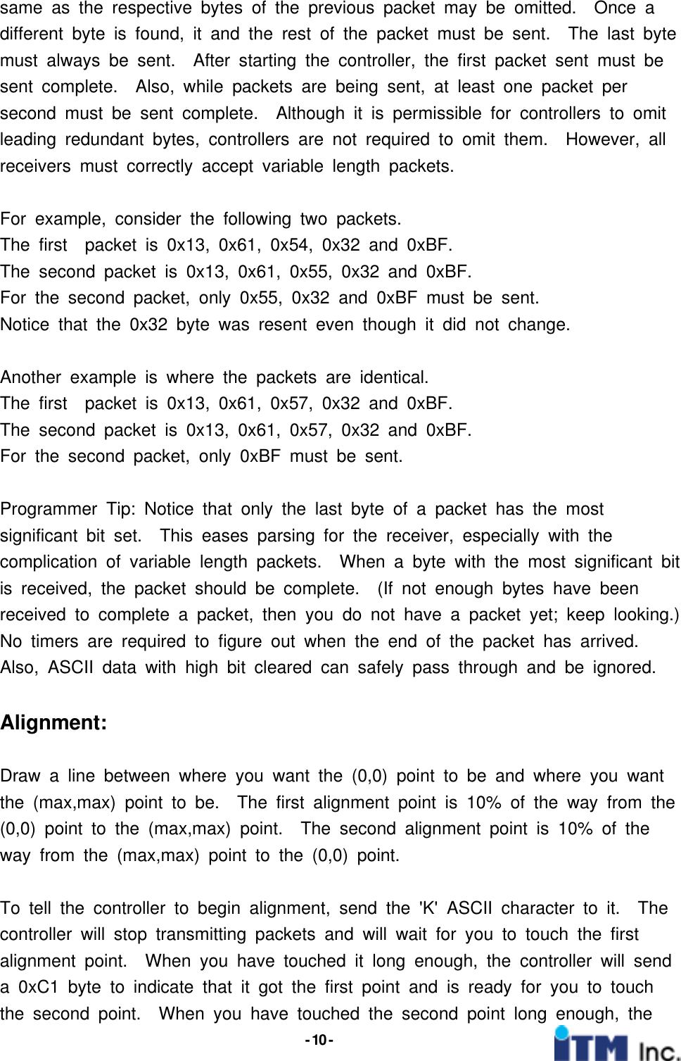
![- 6 -ITM ToucHand ordering and part identificationITM ToucHand controller board part numbering guide:I S4 0 0ITM Serial4-wire 0-RS232 0Usb5-wireCapacitive1-PS/22-CustomKitTouch screenType ControllerType CommunicationType OptionsExample:I4S00 Standard 4-Wire Resistive Analog Touch screen controller for RS-232ITM ToucHand controller firmware label identifier guide:Firmware revision #Hex Rev # 00-FFDate CodeType4:4-wire5:5-wireC : CapacitiveCommunicationS : Standard orRs-232P : PS/2C:CustomS014 YYWWExample:4S10-[date code] 4-wire resistive, Standard firmware, rev: 10](https://usermanual.wiki/ITM/TPMA111/User-Guide-230840-Page-6.png)