ITM TPMA111 4 Wires Analog Resistive Touch Screen User Manual
ITM INC 4 Wires Analog Resistive Touch Screen
ITM >
User Manual

Setup and Users Manual
ITM Controller Board
for 4-Wire Resistive Touch Screen
(Revision 0.0)

- 2 -
Table of Contents
COMPANY AND GENERAL INFORMATION.........................................................3
Mailing Address:
World Wide Web Address:
Copyright Information:
User Information:
Edition Information:
WARNING.................................................................................................................4
Warning:
Note:
INTRODUCTION.......................................................................................................5
ITM ToucHand ORDERING AND PART IDENTIFICATION..................................6
ITM ToucHand controller board part numbering guide:
ITM ToucHand controller firmware label identifier guide:
FEATURES OF ITM TOUCH SCREEN CONTROLLER.......................................7
ITM Software and Device Drivers:
Communication Options:
Transmission Speed:
Touch Screen Interface:
Resolution:
Calibration:
Note about software calibration:
Power Requirement:
COMMUNICATION FORMAT..................................................................................9
Packet Format:
Alignment:
ITM BOARD DIAGRAM.........................................................................................11
COMMUNICATION CABLE AND CONNECTION DIAGRAMS...........................12
ITM 4-WIRE TOUCH SCREEN CONNECTION DIAGRAMS..............................12

- 3 -
Company and General Information
Mailing address:
ITM INC.
#880-3, Kwanyang-Dong, Dongan-Ku,
Anyang-City, Kyunggi-Do, 431-060 Korea
Phone: +82-31-421-6114
Fax: +82-31-422-6118
e-mail: touch@itm.co.kr
World Wide Web Address:
http://www.itm.co.kr
Copyright Information:
This m an ual is200 1 I T M I nc . A ll rights reserved.
Printed in the Republic of Korea.
Reproduction of the contents of this copyrighted material in whole or in part, by
any means mechanically or electronic, for any purpose, without the written
permission of ITM Inc. is prohibited.
User Information:
The information in this document is subject to change without notice.
No part of this document may be reproduced or transmitted in any from or by
any means, electronic or mechanical, for any purpose, without the express written
permission of ITM Inc..
Those responsible for the application and use of ITM Inc. products and
documentation are assumed to have taken all necessary steps to insure that the
application of ITM Inc. products meet safety and performance requirements
including any laws, regulations, codes and standards associated with user
application.
Edition Information:
Printed on: 12 November, 2001
Documents Part number: ITM_MA11100_USERS.gul

- 4 -
Warning:
Although ITM has taken steps to protect your touch screen controller from
transient voltage, it is important to make all grounding, communication and touch
screen connections to the controller and touch screen before powering on our
computer, video monitor or touch screen controller.
Failure to follow this procedure may result in damage to your controller and/or
communication port.
NOTE:
All connection settings are identical. Please contact ITM if you have any
questions regarding your hardware revision. The board revision and firmware
release can be found directly on your ITM touch screen controller board.
INFORMATION TO THE USER
This equipment has been tested and found to comply with the limits for a Class B
digital device, pursuant to part 15 of the FCC Rules. These limits are designed to
provide reasonable protection against harmful interference in a residential
installation. This equipment generates, uses and can radiate radio frequency energy
and, if not installed and used in accordance with the instructions, may cause
harmful interference to radio communications. However, there is no guarantee that
interference will not occur in a particular installation. If this equipment does cause
harmful interference to radio or television reception, which can be determined by
turning the equipment off and on, the user is encouraged to try to correct the
interference by one more of the following measures:
-. Reorient or relocate the receiving antenna.
-. Increase the separation between the equipment and receiver.
-. Connect the equipment into an outlet on a circuit different from that to which the
receiver is connected.
-. Consult the dealer or an experienced radio/TV technician for help.
WARNING
Changes or modifications not expressly approved by the manufacturer could void
the user’s authority to operate the equipment.
This device complies with Part 15 of the FCC Rules. Operation is sub
ject to
the following two conditions: (1) this device may not cause harmful
interference, and (2) this device must accept any interference received,
including interference that may cause undesired operations.

- 5 -
Introduction:
This manual has been written for users of the ITM Inc. ToucHand touch screen
controller boards in combination with the ITM ToucHand device drivers.
The ITM ToucHand controllers were developed for high performance touch input
applications.
The ITM ToucHand touch screen controller and software described within this
document is assumed to be used with four wire analog resistive touch screen
products manufactured by a variety of touch screen manufactures.
Touch screens vary with regard to light transmission, sensitivity and electrical
characteristics between manufactures.
The ITM ToucHand controller allows for 12-bit resolution of an analog resistive
touch screen. The resolution of the ITM TM controller is 4,096 x 4,096(16,777,216
point in the field).
Because touch screen quality and resistance varies from touch screen
technologies and manufacturers the actual overall resolution may vary (slightly)
between touch screen overlay manufacturer's products.
ITM ToucHand device drivers are designed to integrate smoothly with PC based
operating systems. If you have a touch only application you may save
considerable cost by using the ITM controller. Please contact ITM for information
regarding our lower cost touch screen controller products.
A great deal of attention has been paid to eliminate potential problems with
various touch screen manufactures. ITM has tested the ITM controllers with the
following touch screen overlay manufacturer's analog resistive touch screens:
ITMTM,Gunze
TM,MicroTouch
TM, DynaproTM, NishaTM.
- 6 -
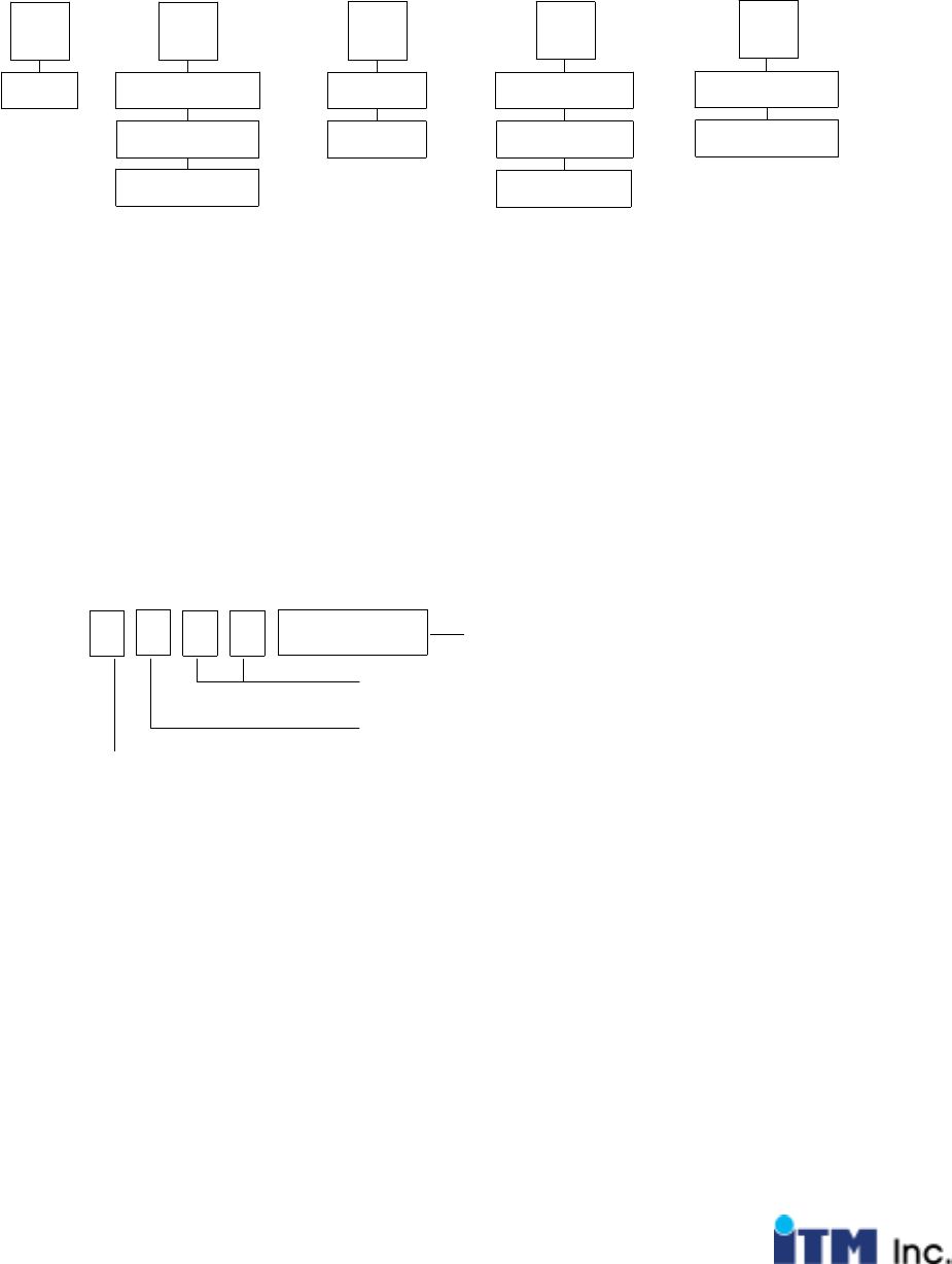
ITM ToucHand ordering and part identification
ITM ToucHand controller board part numbering guide:
I S4 0 0
ITM Serial4-wire 0-RS232 0
Usb
5-wire
Capacitive
1-PS/2
2-Custom
Kit
Touch screen
Type Controller
Type Communication
Type Options
Example:
I4S00 Standard 4-Wire Resistive Analog Touch screen controller for RS-232
ITM ToucHand controller firmware label identifier guide:
Firmware revision #
Hex Rev # 00-FF
Date Code
Type
4:4-wire
5:5-wire
C : Capacitive
Communication
S : Standard or
Rs-232
P : PS/2
C:Custom
S014 YYWW
Example:
4S10-[date code] 4-wire resistive, Standard firmware, rev: 10

- 7 -
Features of ITM ToucHand touch screen controller
ITM Software and Device Drivers:
All ITM products are designed be used with ITM ToucHand device drivers. ITM
Company develops, supports and maintains all products sold with the ITMTM or
ToucHand trademark.
ITM does not use third party technical resources to develop any of its software or
hardware products. Typically there is no additional charge for ITMTM device drivers.
Drivers are available for WindowsTM, Windows NTTM, Windows CETM,Linux
TM.
If you require a custom or modified driver for your application, please contact ITM
Inc. All user manuals and drivers are available at the ITM web site.
All rights reserved. ITM terms and conditions apply to all applications using ITM
hardware, firmware or software.
Communication Options
RS232 (9600 or 19200 baud rate)
1StartBit,8DataBits,1StopBit,noparity
PS/2, Personal System / 2
Transmission Speed
~192 points per second @9600 Baud
Touch Screen Interface
Analog Resistive 4 wire
Resolution
12 bit (4096 x 4096)
Calibration
Internal calibration available for custom configuration only.
Software (driver) calibration for all PC configurations.
Note about software calibration
The touch screen can be connected upside down. The calibration routine will
identify the correct position of the touch screen overlay.

- 8 -
Power Requirement
DANGER: If the static ground mounts are not terminated to ground, the static
protection will not function properly and you may destroy your ITM ToucHand
controller board, your communication port or both. See diagram for more
details
External Regulated power: 5Vdc +/- 10%
- 9 -
Communication Format
The controller communicates at 9600 bits per second (baud), 8 data bits, no
parity bit, and 1 stop bit When the controller is started, it sends a Plug and Play
(PnP) message. The content of this PNP message has yet to be determined.
For now, it is "Hello PnP". After the PnP message, the controller sends packets
while the touch panel is touched.
Packet Format
Packets send three values:
12 bit x coordinate
12 bit y coordinate
8bitz
Z is a rough, non-linear, non-calibrated, measure of pressure or contact area. A
value of 0 means no pressure or contact. 0xFF is maximum pressure or contact.
As long as contact is maintained, 192 packets per second will be sent. When
contact is lost, one more packet with a z value of 0 will be sent. The x and y
values of such a packet are meaningless.
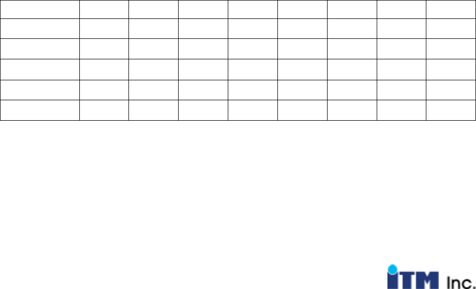
The format of packets is:
msb d7 d6 d5 d4 d3 d2 d1 lsb d0
First Byte 0LIFT RFE y11 y10 y9 y8 y7
Second Byte 0 z7 z6 x11 x10 x9 x8 x7
Third Byte 0 y6 y5 y4 y3 y2 y1 y0
Fourth Byte 0 x6 x5 x4 x3 x2 x1 x0
Fifth Byte 1 0 z5 z4 z3 z2 z1 z0
x0, y0 and z0 are the least significant bits.
RFE means reserved for future expansion. For now it is zero.
LIFT = if '1' process as lift off packet.
The packets are variable length. Bytes at the beginning of a packet that are the

- 10 -
same as the respective bytes of the previous packet may be omitted. Once a
different byte is found, it and the rest of the packet must be sent. The last byte
must always be sent. After starting the controller, the first packet sent must be
sent complete. Also, while packets are being sent, at least one packet per
second must be sent complete. Although it is permissible for controllers to omit
leading redundant bytes, controllers are not required to omit them. However, all
receivers must correctly accept variable length packets.
For example, consider the following two packets.
The first packet is 0x13, 0x61, 0x54, 0x32 and 0xBF.
The second packet is 0x13, 0x61, 0x55, 0x32 and 0xBF.
For the second packet, only 0x55, 0x32 and 0xBF must be sent.
Notice that the 0x32 byte was resent even though it did not change.
Another example is where the packets are identical.
The first packet is 0x13, 0x61, 0x57, 0x32 and 0xBF.
The second packet is 0x13, 0x61, 0x57, 0x32 and 0xBF.
For the second packet, only 0xBF must be sent.
Programmer Tip: Notice that only the last byte of a packet has the most
significant bit set. This eases parsing for the receiver, especially with the
complication of variable length packets. When a byte with the most significant bit
is received, the packet should be complete. (If not enough bytes have been
received to complete a packet, then you do not have a packet yet; keep looking.)
No timers are required to figure out when the end of the packet has arrived.
Also, ASCII data with high bit cleared can safely pass through and be ignored.
Alignment:
Draw a line between where you want the (0,0) point to be and where you want
the (max,max) point to be. The first alignment point is 10% of the way from the
(0,0) point to the (max,max) point. The second alignment point is 10% of the
way from the (max,max) point to the (0,0) point.
To tell the controller to begin alignment, send the 'K' ASCII character to it. The
controller will stop transmitting packets and will wait for you to touch the first
alignment point. When you have touched it long enough, the controller will send
a 0xC1 byte to indicate that it got the first point and is ready for you to touch
the second point. When you have touched the second point long enough, the
- 11 -
controller will send a 0xC2 byte to indicate that it got the second point, and that
the alignment was successful and is finished.
The controller will send a 0xC0 byte to indicate that the alignment was
unsuccessful. Unsuccessful alignment is usually due to the two alignment points
being too close.
Programmer Tip: Notice that the 0xC0, 0xC1 and 0xC2 alignment
status bytes that can be sent by the controller can not be confused for packet
data because the two most significant bits are set.
Whenever the controller receives serial data, it stops transmission of packets for
several seconds.
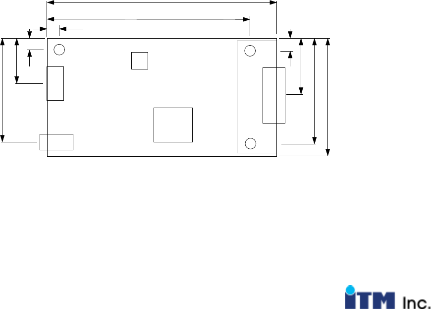
ITM ToucHand Board Diagram
59.65
52.07
3.81
3.81 12.7
4.04
29.01
33.02
16.51
27.67
- 12 -
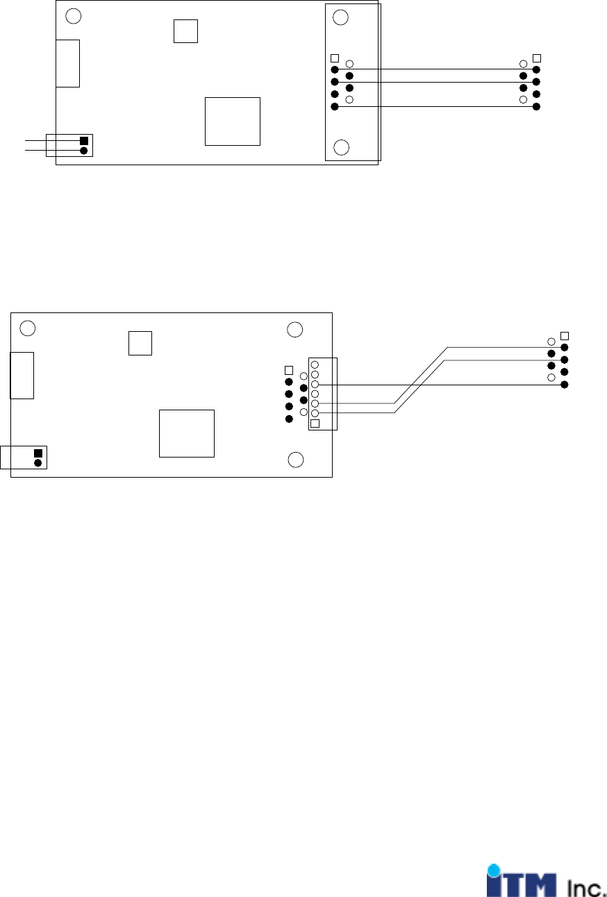
Communication Cable and Connection Diagrams
RS-232 Communication Diagram External Power:
Power
Ground
2: TxD
3: RxD
5: GND
3: RxD
2: TxD
PC COM Port
RS-232 Communication Diagram External Power:
PC COM Port
2: TxD
3: RxD
3: RxD
2: TxD
5: GND 5: GND
6: Power
7: Ground
- 13 -
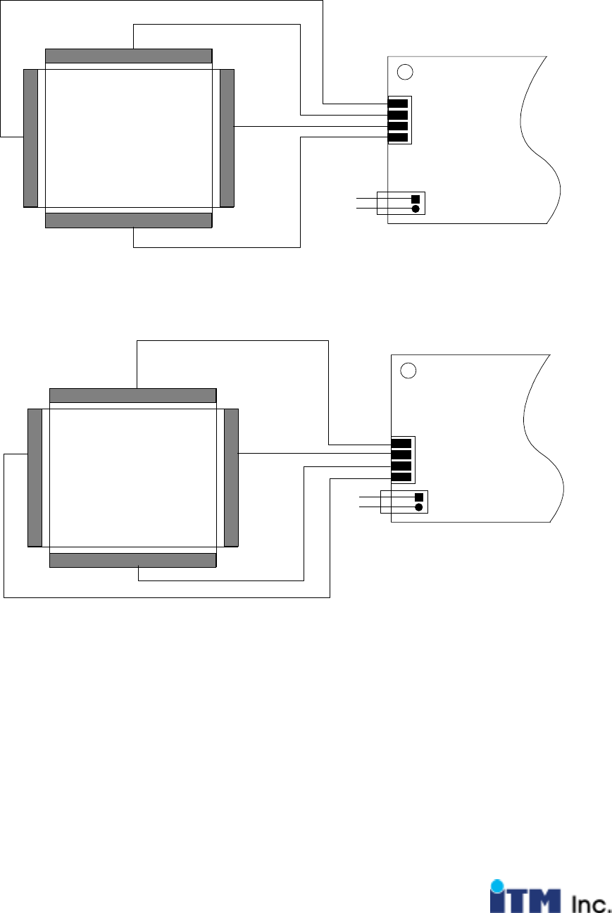
TM Touch Screen Connection Diagrams
4-wire touch screen:
Power
Ground
XL
YL
XR
YU
X+
Y+
X-
Y-
JP1
Power
Ground
XL
YL
XR
YU
Y+
X-
Y-
X+
JP2