Manual
EQUICALOR®
• DC 1010
USER’S GUIDE
Wireless system for independent
management of thermal regulation
MANUAL DE INSTRUCCIONES
Sistema inalámbrico para la automa-
tización de la termorregulación
300546US-10-14
PATENTED
1. CHRONOTHERMOSTAT
Features of the chronothermostat pg. 3
Contents of the package pg. 3
Display and control keys pg. 3
Warnings pg. 4
List of alarms pg. 4
Chronothermostat conditions of warranty pg. 4
Contacts pg. 4
Battery replacement pg. 5
Operating modes pg. 5
Chronothermostat configuration pg. 6
Automatic temperature setting pg. 9
Installing the chronothermostat pg. 10
Technical characteristics of the chronothermostat pg. 12
2. ACTUATOR
Features of the actuator pg. 14
Contents of the package pg. 14
Led indicator and front selector switch pg. 14
Warnings pg. 14
Technical characteristics of the actuator pg. 15
Battery replacement pg. 16
Remote sensor pg. 16
Room comfort temperature adjustment pg. 16
Installing the actuator pg. 17
Manual release pg. 17
3. TECHNICAL SECTION
3 . 1 (CHRONOTHERMOSTAT)
Chronothermostat - setup pg. 18
Association of an actuator with the chrono-
thermostat pg. 19
3 . 2 (ACTUATOR)
Actuator – setup pg. 20
4. FUNCTION NAVIGATION MAP pg. 22
5. APPENDIX pg. 23
INDEX
INSTALLING THE EQUICALOR SYSTEM
1) Identify the zones
Plan out the division of the house into zones, determining
the quantity.
2) Define a position for the chronothermostat
The chronothermostat measures the temperature of the
room where it is installed; therefore, it must be in a position
exposed to good air circulation, at 5 ft above the floor. See
Typical placement of device on pg. 10.
3) Chronothermostat wall installation
Secure the chronothermostat in the desired position and con-
nect it to the boiler. Refer to Wall installation on pg. 11.
CAUTION! Make sure to cut-out the mains voltage to the
electrical system before carry out this procedure.
4) Insert the batteries in the chronothermostat
The chronothermostat requires 3 AA 1.5 V Alkaline batteries. To
insert the batteries refer to Battery replacement on pg. 5.
5) Setting the language, date and time
Enter the data for first start up, as indicated in the para-
graphs Current language, Date and Time (Set time) on pg.
7. To use the control keypad see Chronothermostat Con-
figuration and Menu Navigation on pg. 6.
6) Configuring the zones
Set the number of zones in the house, as indicated in the para-
graph Number of managed zones on pg. 19. To access the
function refer to Chronothermostat Configuration on pg. 6.
7) Insert the batteries in the actuator
Each actuator requires 3 AA 1.5 V alkaline batteries. To insert
the batteries refer to Battery replacement on pg. 16.
8) Installing the actuator
Install the actuators on their respective radiators. Refer to
Installing the actuator on pg. 17.
9) Associate all the actuators to the chronothermostat and
test them
Refer to the chapter Association of an actuator with the
chronothermostat on pg. 19.
QUICK GUIDE
300546US-10-14
CHRONOTHERMOSTAT
[3]
For help see ‘NAVIGATION MAP’ on pg. 22
INTRODUCTION
The EQUICALOR system consists of a chronothermostat
and integrated zone actuators. The chronotermostat
can control your plant, managing temperature control.
The actuators are installed directly on the radiators to
regulate operation in each room.
Both the heating and cooling functions of EQUICALOR
guarantee optimal room temperature and energy
savings during times of the day when the rooms are not
occupied.
The information contained in this manual will help
simplify the customisation of the system and the
consequent reduction in the plant operating costs.
1. CHRONOTHERMOSTAT
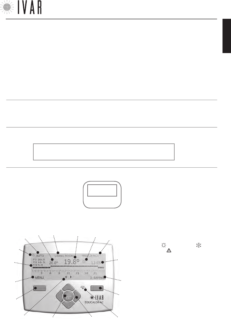
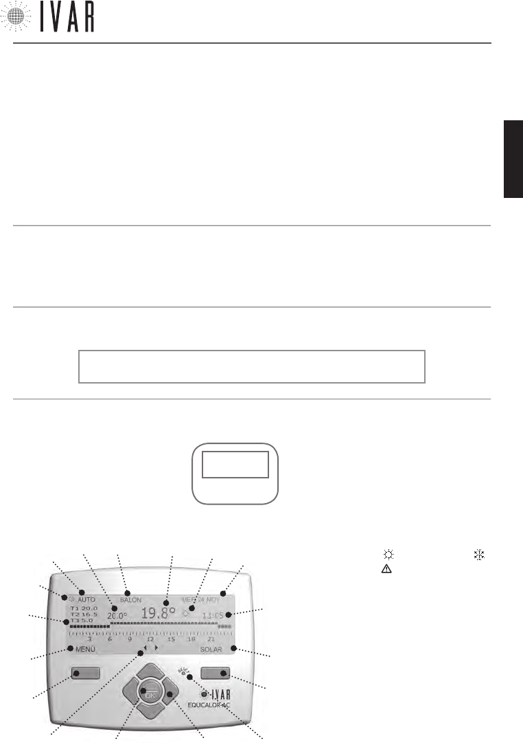
DISPLAY AND CONTROL KEYS
The Control keys are composed of:
• Right multi-function key (1)
• Left multi-function key (5)
• ‘Reset’ key (2)
• Four navigation keys (3)
• ’OK-MODE’ button (4)
NOTE: If the key lock is not active, simply touch
keypad and it will become operational.
CONTROL
KEYS
DISPLAY
*temperature:
T1=T comfort
T2=T saving
T3=T limit
(L)
(I)
(3)(4)
(1)
(5)
(B) (M)
(C)
(2)
(A)
(H)
(G)
(F)
(D) (E)
(D1)
The Display has the following fields:
• Navigation keys icon (A)
• Left multi-function key field: ‘MENU/EXIT/
CANCEL’ (B)
• 7-DAYS Schedule Graph (C) T1, T2, T3 (see
note below*)
• Mode enabled (D)
• Temporary mode on (D1)
• Set temperature (E)
• Currently selected zone (F)
• Temperature reading <only ZONE1> (G)
• WINTER mode , SUMMER mode and
Alarm Reminder (H)
• Date (I) and Time (L)
• Right multi-function key field: ’ENTER/EDIT/
ENTER/VIEW/D. SAVING (M)
• Chronothermostat • Stylus alkaline batteries • This user’s manual
CONTENTS OF THE PACKAGE
FEATURES OF THE CHRONOTHERMOSTAT
The EQUICALOR-AC chronothermostat is able to
independently manage the individual rooms, controlling
up to 8 zones. It also allows direct control of the wall-
mounted boiler.
300546US-10-14
ENGLISH

CHRONOTHERMOSTAT
[4]
WARNINGS
1 . Adjustment of the chonothermostat’s advanced
settings should preferably be carried out by the installer.
2 . It is important to verify that the batteries are
working properly to prevent the heating/cooling system
from shutting down due to a lack of power to the
chronothermostat.
3 . Observe the following directions for using the
batteries: when it is time to dispose of them, place them
separately into the appropriate recycling container;
follow the installation instructions provided; when the
device is not used for a prolonged period of time, make
sure to remove the batteries; avoid connecting the
metal poles that are in contact with the batteries in
order to prevent a short circuit; always use the type of
batteries specified in this manual; do not mix different
batteries, old and new batteries or alkaline batteries with
standard or zinc coal batteries; the use of rechargeable
batteries results in less operating autonomy when
compared to non-rechargeable batteries.
4 . If the device causes interference with other electrical
equipment, immediately remove them from the area.
5 . Do not dispose of the device in the environment
at the end of its life cycle. Dispose of the device in
compliance with current legislation.
6 . The chronothermostat must only be installed by
authorised personnel in accordance with current
legislation and regulations and with the mains voltage
switched off.
7 . In the event of a problem(s), a ‘List of Alarms’
appears when the display is switched on. See the
following paragraphs.
CHRONOTHERMOSTAT CONDITIONS OF WARRANTY
I.V.A.R. S.p.A. is insured against damage caused to third
parties due to product manufacturing defects in accord-
ance with the terms and limits set out in Legislative De-
cree 206/2005. The maximum insurance coverage is €
3,000,000.00 per claim, per year. The liability of IVAR for
damages caused by defective products is governed by
the general sales conditions and by Legislative Decree
206/05 (art.114-127) and is valid for 2 years after the
product’s installation.
I.V.A.R. S.p.A. ensures the compliance and the proper
functioning of its products in accordance with the terms
of Legislative Decree 206/05.
LIST OF ALARMS
In case a working error occurs, the system keeps track
of the anomaly.
If the error persists, a warning is shown when the dis-
play lights up for the first time. This message can be
read at any time in section ‘Alarm history’ for full details.
(See relative paragraph on pg. 18)
The access path is as follows: MENUàSETTINGSàAD-
VANCED SETINGS àPLANTàDIAGNOSTICSàALARM HISTORY
NOTE: the icon Alarm Reminder ’ ’ appears in case of
error and turns off as soon as the ‘HISTORY’ menu has
been opened.
CONTACTS
IVAR US, Inc.
Mailing Address: PO Box 8015, Elkridge, MD 21075
T:1-855-9-IVAR-US
www.ivar-us.com
info@ivar-us.com
I.V.A.R. S.p.A.
Via IV Novembre, 181
25080 Prevalle (BS) - Italy
T: +39 030 68028 - F: +39 030 6801329
www.ivar-group.com
info@ivar-group.com
300546US-10-14
CHRONOTHERMOSTAT
[5]
For help see ‘NAVIGATION MAP’ on pg. 22
B1 B2
B3
FIG.
2
NOTE: When switched on, the display prompts selection
of the language, time and date; the default language is
English (To complete this procedure, see ‘Menu Naviga-
tion on pg. 6. This paragraphs explains how to use
the control keypad).
The low battery alarm (L BATT) indicates that the bat-
teries are almost discharged and that they will continue
to function in anti-freeze mode for 15 days, until they
are fully discharged; therefore, they must be replaced
to restore operability. For more information about the
alarms, see ‘Diagnostics (Alarm History)’ on pg. 18;
the alarms concern both the chronothermostat and the
actuators. Removing the batteries does not cancel the
settings made.
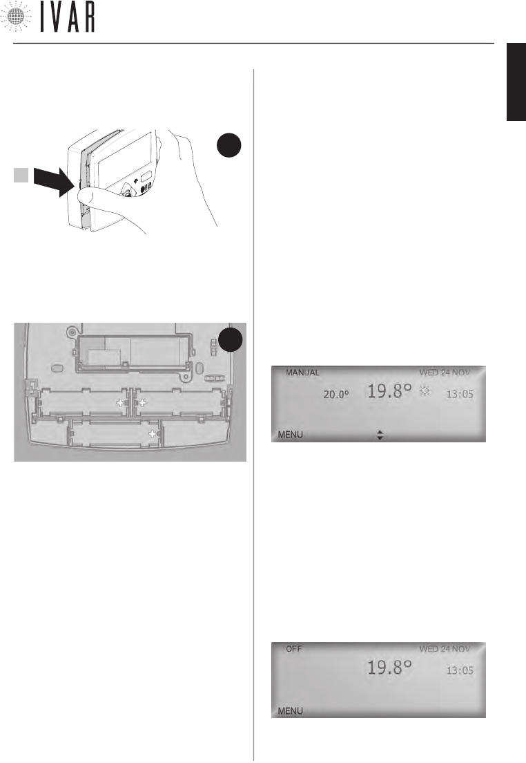
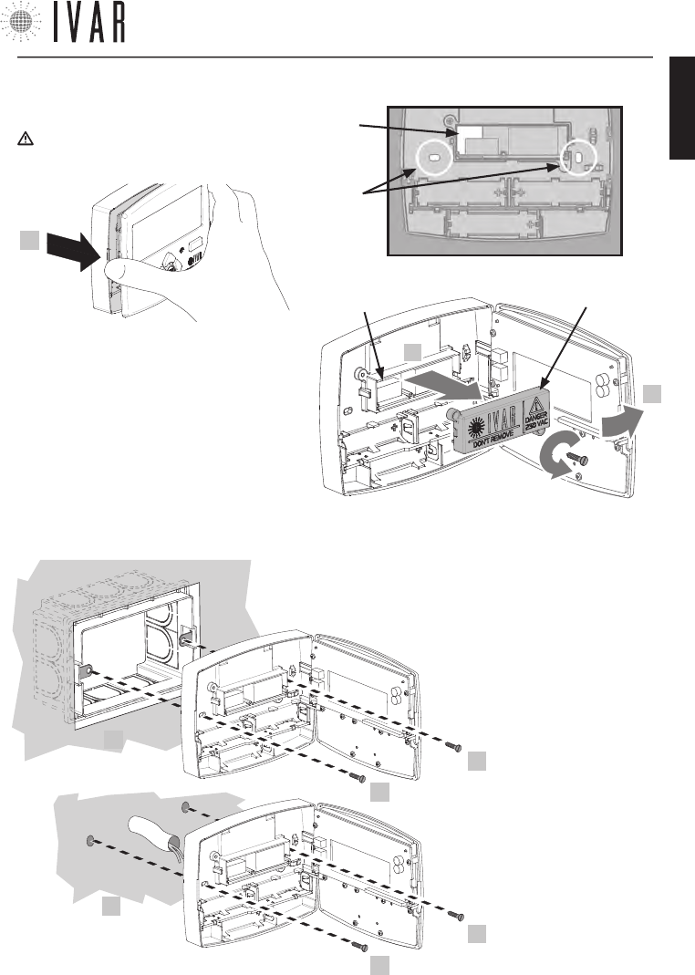
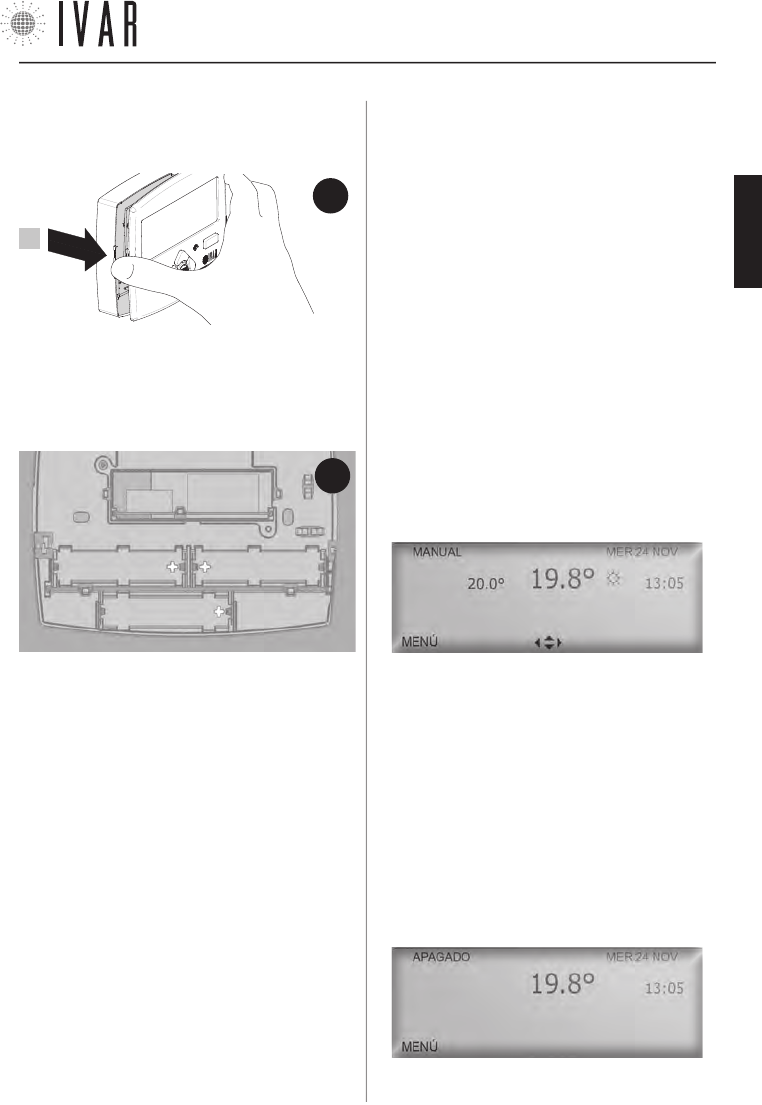
To insert or replace the batteries, open the front panel
of the chronothermostat (See figure-1). Then, place the
batteries in their housings (B1, B2, B3), making sure to
place them in the direction indicated on the bottom of
each housing (See Figure-2).
BATTERY REPLACEMENT
The chronothermostat requires 3 AA 1.5 V Alkaline bat-
teries. The batteries must be inserted in order to oper-
ate the equipment.
OPERATING MODES
The Chronothermostat operates in three different
modes: Automatic, Manual and OFF. The Enabled Mode
icon indicates which of the three modes is currently
enabled. To activate the display, simply touch any key.
During normal chronothermostat operation, the display
will show the information regarding the status of the
system relative to the mode currently enabled for 30
seconds (When operating in ‘Automatic mode’ the Cur-
rently selected zone icon specifies the zone to which
the information refers. To review the different zones,
use the Left/Right arrows). To switch from one mode
to another, press OK-MODE repeatedly until the desired
mode is displayed.
Manual Mode
[
MENUàMODEàMANUAL MODEàENABLE MANUAL MODE
]
Defines a set temperature that will be maintained in all
the zones (SET TEMPERATURE).
The Up/down keys (navigation keys) are used to change
the Set temperature, increasing or decreasing it by 1°F.
Switching to another mode, interrupts the Manual mode.
Shutdown mode
[
MENUàMODEàSHUTDOWN MODEàSHUTDOWN
]
Shutdown mode disables the system, switching to the
anti-freeze mode.
This program ensures a minimum ambient temperature
of 41 °F to protect the system. On the display the time,
date and temperature can be read. It is also possible to
access the menu.
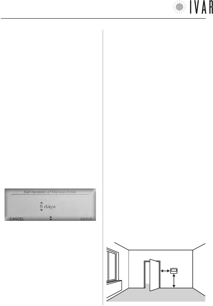
NOTE: to maintain the Manual or Shutdown mode for a
FIG.
1
1
300546US-10-14
ENGLISH
CHRONOTHERMOSTAT
[6]
To start, press the left multi-function key
defined period of time, see the paragraph ‘Automatic
Temperature setting’ on pg. 9.
Automatic mode
[
MENUàMODEàAUTOMATIC MODEàENABLE AUTOMATIC MODE
]
For information regarding this mode, see pg. 9.
CHRONOTHERMOSTAT CONFIGURATION
To configure the chronothermostat options you must
access the MENU. If the display is off, activate it by sim-
ply pressing any key.
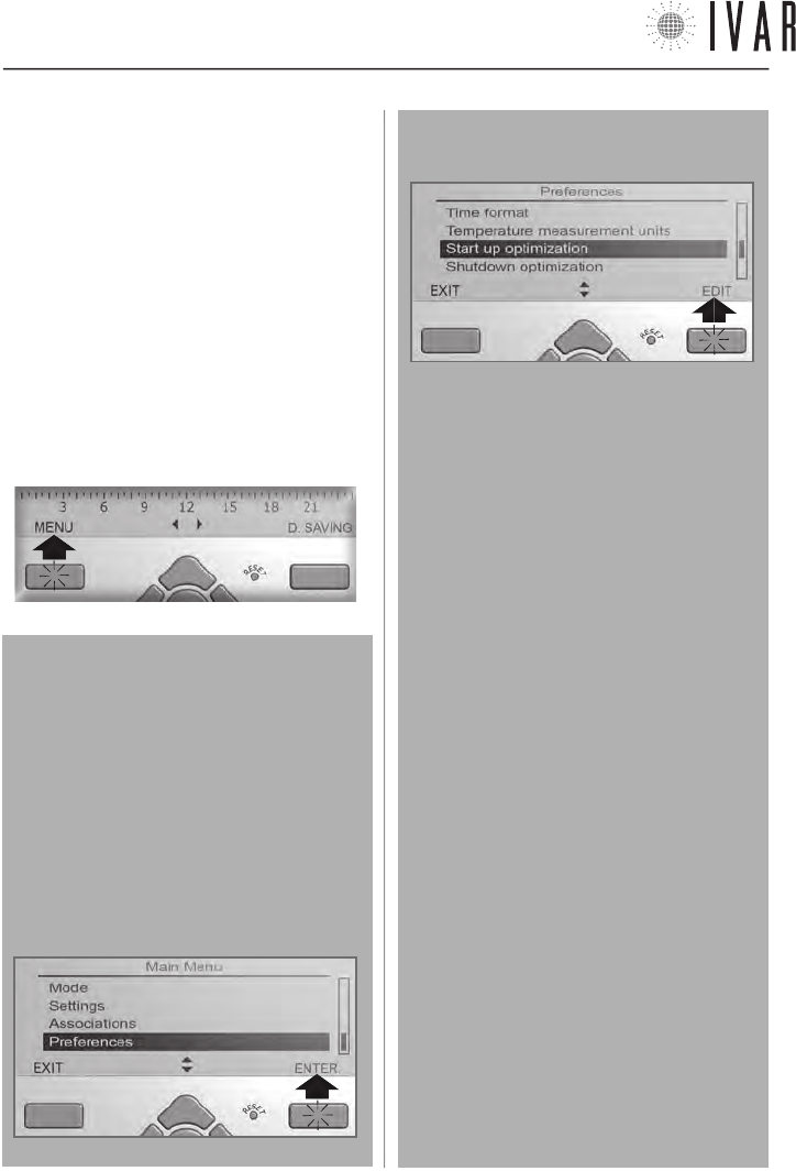
Press the Left multi-function key as shown to view a
list of sections.
Menu Navigation
Using the Up/down keys (navigation arrows), select
the required field. Press OK or the Right multi-func-
tion key to access the highlighted option. Some ad-
vanced options require pressing ENTER another time
before you can proceed. The header shows the name
of the page for easier navigation.
The following example shows the procedure for ac-
cessing the ‘Start up optimization’ option
1 - scroll the list with the UP/DOWN keys and select
‘Preferences‘ and then press the right multi-function
key to access.
2 - scroll the list with the UP/DOWN keys to select
‘Start up optimization‘ and then press the right mul-
ti-function key to edit.
In the various editing options, the Multi-function
keys allow proceeding step by step until these pro-
cedures are complete.
Refer to the following list (Note that after 30 sec-
onds, if no key is pressed, the system switches off
the display, exiting the menu).
List of key functions
(multi-function and arrow keys)
• ENTER to access a section.
• EDIT to begin a procedure.
• ENTER to complete a procedure after editing.
• VIEW to consult a page.
• EXIT to close a section.
• CANCEL to go back without completing the edit.
• STANDARD/D. SAVING to change the time.
• Up/down (navigation arrows) to scroll through a list
or edit a temperature, date or time value. Using
the arrows, press down to edit faster.
• Left/right (navigation arrows) to switch from one
value field to another.
NOTE: refer to the ‘Function navigation map’ on pg.
22 for the complete list of the menu sections and
their relative access path.
NOTE: at the beginning of each function description,
its access path is indicated; for example:
[MENUàSETTINGSàCURRENT LANGUAGE].
300546US-10-14
CHRONOTHERMOSTAT
[7]
For help see ‘NAVIGATION MAP’ on pg. 22
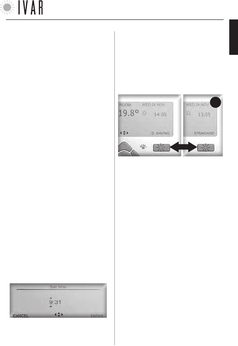
Time (Daylight saving time)
[
MENUàSETTINGSàTIMEàD.SAVING TIME
]
Access the Daylight saving time section to manage the
time change. Use the Up/down keys to edit the set-
tings. Select ON to activate the time change, or OFF to
maintain the standard time throughout the year. When
finished, press ENTER. After having activated the time
change, during normal operation, the display will indi-
cate the type of time enabled (see Figure-3).
In this case, every time the Right Multi-function key is
pressed the time changes from standard to daylight
saving time and vice versa, allowing the clock to be up-
dated on the date established.
Summer set, Winter set, Zones, Summer adjustment,
Summer/Winter Mode
[
MENUàSETTINGSà...
]
See pg. 9.
Contrast and Brightness Adjustment
[
MENUàSETTINGSàCONTRAST
]
[
MENUàSETTINGSàBRIGHTNESS
]
These control the contrast of the display and the in-
tensity of the backlighting. Use the Up/down arrows
to select a new adjustment and then press ENTER. The
default brightness setting is ‘Minimum’, which ensures
optimal battery life.
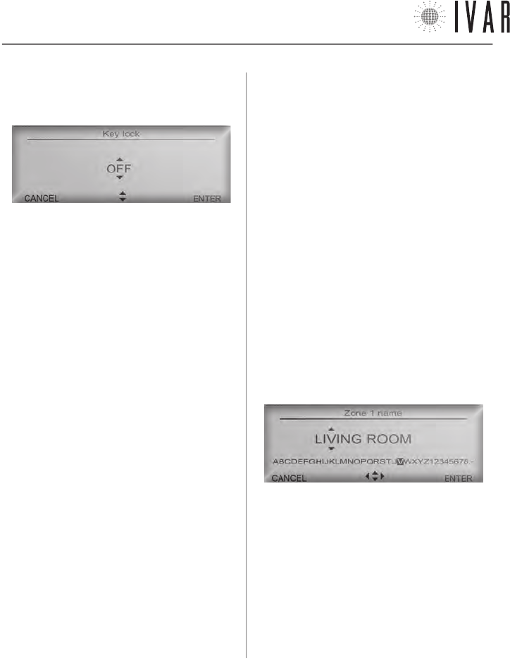
Key lock
[
MENUàSETTINGSàKEY LOCK
]
Access the Key lock section to enable and disable this
function.
1) Select ON, using the Up/down keys to protect the de-
vice from accidental changes being made. Then press
ENTER. In this case, if the keypad has not been used for
thirty seconds, the display lighting switches off and the
keypad is locked.
FIG.
3
SETTINGS - ASSOCIATIONS -PREFERENCES
A list of menu sections follows.
Reset
[
‘reset’ KEY
]
If an anomaly is noted, manually restart the device. To
do this, press the Reset key on the keypad using a pencil
or paper clip.
NOTE: the settings defined previously are NOT lost dur-
ing this operation.
Current language
[
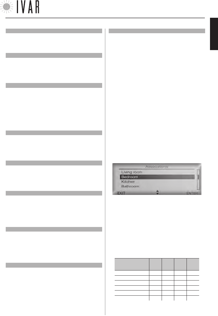
MENUàSETTINGSàCURRENT LANGUAGE
]
The chronothermostat provides for the use of 9 lan
-
guages (Italian, English, French, German, Spanish, Por
-
tuguese, Flemish, Czech, Norwegian). Access the Current
Language section (See ‘Menu Navigation’ on pg. 6).
To edit the language option, use the Up/down keys and
select the desired language from the list. Press ENTER
to complete the procedure.
Date
[
MENUàSETTINGSàDATE
]
Access the Date section to change the current date (See
‘Menu Navigation’ on pg. 6). Use the Left/right key
to switch from editing the ‘day’ to editing the ‘month’
or ‘year’. Press Up/down to change the day/month/year.
Press ENTER to complete the procedure or CANCEL to
exit the procedure and return to the previous menu
without making any changes.
Time (Set Time)
[
MENUàSETTINGSàTIMEàSET TIME
]
Access the Set time section to change the current time
(See ‘Menu Navigation’ on pg. 6). Use the Left/right
key to switch from editing ‘hours’ to editing ‘minutes’
and vice versa.
Press Up/down to change the hours/minutes of a unit.
Press ENTER to complete the procedure.
300546US-10-14
ENGLISH
CHRONOTHERMOSTAT
[8]
With each subsequent touch of the keypad, the display
will light up for 10 seconds and indicate the key to press
to unlock the keypad.
and OFF disables it. Use the Up/down arrows to edit the
setting and then press ENTER. The optimization process
is self-regulating and its precision during normal opera-
tion is refined each day, improving yield.
If the Start up optimization is enabled, start up takes
place in advance so that the Comfort temperature is
effectively reached at the precise moment set in the
programming parameters. Similarly Shutdown optimi-
zation (if enabled) will anticipate shutdown in order to
obtain an optimized temperature Ts when entering the
T2 time band (Ts=T1-Tred with Tred equal to the value of
Prestart savings reduction).
Zone names
[
MENUàPREFERENCESàSET ZONE NAMES
]
Allows you to customize the names of each zone. To
begin, select a zone using the Up/down arrow and then
press ENTER. Use the Up/down arrows to change a letter
and the Left/Right arrows to move to the next letter.
Follow the instructions in the ‘Character scroll bar’, lo-
cated under the name, to compose text.
2) Select OFF to cancel the protection and then press
ENTER. In this case, the display will light up at each touch
of the keypad until the next shutdown, which occurs af-
ter 30 seconds of inactivity.
Associations
[
MENUàASSOCIATIONS
]
Refer to the paragraph ‘Association of an actuator with
the chronothermostat‘ on pg. 19 .
Time format (12, 24)
[
MENUàPREFERENCESàTIME FORMAT
]
If this option is changed, the time field will be expressed
in format 24 (e.g.: 18:25) instead of format 12 (e.g.:
6:25 PM). Use the Up/down keys to configure the option.
When finished, press ENTER.
Temperature measurement units
[
MENUàPREFERENCESàTEMPERATURE MEASUREMENT UNITS
]
If this option is changed, all the temperatures will be
expressed on the display in Celsius instead of Fahren-
heit. Use the Up/down arrows to edit the setting and
then press ENTER.
Start up and shutdown optimization (Functions only ac-
tive in Winter mode)
[
MENUàPREFERENCESàSTART UP OPTIMIZATION
]
[
MENUàPREFERENCESàSHUTDOWN OPTIMIZATION
]
Allows enabling plant pre-activation and anticipated
shutdown in ‘Automatic Mode’. ON enables optimization
To delete a letter, select the ‘Blank’ at the end of the bar.
When finished, press ENTER to make the change.
300546US-10-14
CHRONOTHERMOSTAT
[9]
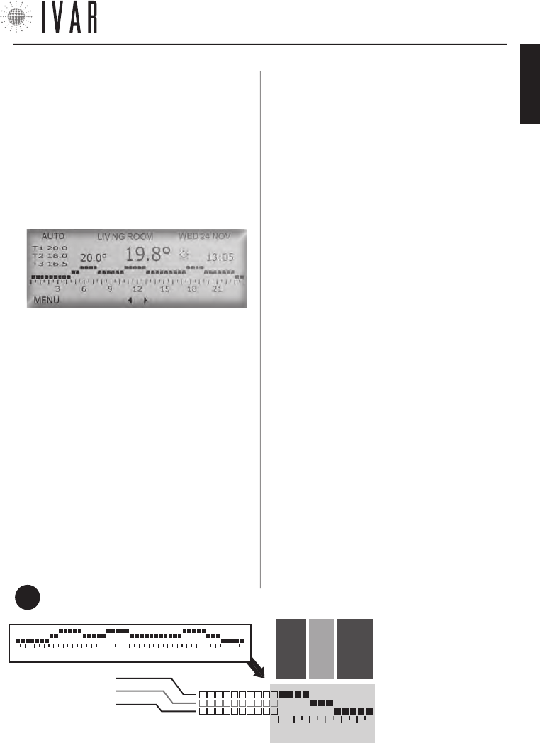
For help see ‘NAVIGATION MAP’ on pg. 22
In this example, the temperature will be 68 degrees
from 18:00 to 20:00, 65 degrees from 20:00 to 21:30
and 62 degrees from 21:30 to 24:00.
FIG.
4
AUTOMATIC TEMPERATURE SETTING
Enable Automatic Mode (Automatic Mode)
[
MENUàMODEàAUTOMATIC MODEàENABLE AUTOMATIC MODE
]
If Automatic mode is enabled, the chronothermostat
follows a weekly schedule to control the system.
It is therefore possible to set, for each of the 7 days,
during which time bands to offer the Comfort (T1), Sav-
ing (T2) or Limit (T3) temperature.
Access the Mode section and select Automatic Mode us-
ing the Up/down arrows (See ‘Menu Navigation’ on pg.
6 for further instructions).
Then press ENTER twice, to activate the option.
Winter/Summer Mode
[
MENUàSETTINGSàWINTER/SUMMER MODE
]
Enables the system to control heating and cooling, giv-
ing priority to the winter set or summer set, respectively
(For information on the sets see the following para-
graphs).
Access the Winter/Summer Mode and use the Up/down
arrow to select Winter or Summer, then press ENTER.
‘Winter Set’ and ‘Summer Set’
[
MENUàSETTINGSàWINTER SET
]
[
MENUàSETTINGSàSUMMER SET
]
To define the 3 temperature ranges into which the in
7-DAYS Schedule Graph is divided, proceed as follows
(the 3 ranges are represented by the horizontal lines of
the graph; see Figure-4 and ‘Managing the temperature
sets’ on pg. 23).
Access the Winter Set section or the Summer Set sec-
tion depending on the mode you wish to work in (see
‘Summer/Winter Mode’). Use the Up/down to highlight
the required field and then press ENTER.
Using the Up/down arrows, select Set comfort to cus-
tomize temperature T1, Set saving for T2, or Set limit
for T3. By appropriately adjusting the Saving and Limit
temperatures, the user is able to perfect saving man-
agement.
Highlight a field and press ENTER. With every touch of
the Up/down arrows the temperature value increases or
decreases by 1 °F.
When finished, press ENTER.
Zones - Weekly Schedule
[
MENUàSETTINGSàZONES
]
When the WINTER mode is enabled, access the Zones
section to customize the 7-DAYS Schedule Graph of
any zone in the home (This section lists many zones, or
rather the number defined using the ‘Number of man-
aged zones’ option - see pg. 19).
The initial number of zones is 2 and this can be in-
creased to a maximum of 8). Select a zone with the
Up/down arrows and press
ENTER. Using the Up/down
arrows select the day of the
week you wish to set and
press ENTER. Now use the
Left/right buttons to high-
light the time bands to be
edited (48 vertical markers
divide the day into 30 min
intervals). Then press Up/
down to assign T1, T2 or T3
18 21
LINE 1 – e.g.: 68°
LINE 2 – e.g.: 65°
LINE 3 – e.g.: 62°
3 6 9 12 15 18 21
FROM 18:00
TO 20:00
FROM 20:00
TO 21:30
FROM 21:30
TO 24:00
7-DAYS SCHEDULE GRAPH
(EXAMPLE)
300546US-10-14
ENGLISH
CHRONOTHERMOSTAT
[10]
INSTALLING THE CHRONOTHERMOSTAT
Follow the instructions below to operate device:
1)
Choose a location for the device and mount it on the wall.
2) Insert the batteries.
3) Associate each actuator to the chronothermostat,
defining the various zones of the building. (See the
paragraph, ‘Association of an actuator with the chrono-
thermostat‘ on pg. 19).
Typical placement of device
The chronothermostat measures the temperature of
the room where it is installed; therefore, it must be in
a position exposed to good air circulation, at 5 ft above
the floor.
The following instructions must be followed.
• DO NOT place near a radiator.
• DO NOT place near doors.
• DO NOT place on perimeter walls.
•
DO NOT place in correspondence to piping inside the walls.
• DO NOT place in rooms with exceptional temperature
and humidity conditions (For example the kitchen
and bathroom).
• DO NOT place where the device may come into con-
tact with water.
• DO NOT expose to direct sunlight.
NOTE: when placing the thermostat, it is necessary to
verify that the actuators are located within a certain
range. In ideal conditions - without any obstacles - this
range covers 33 yd. Among the factors that can affect
transmission performance, humidity and the architec-
tural features of the building must be considered.
5 ft
1 ft
to the time interval selected. To complete the change,
press ENTER. It is immediately possible to decide
whether to apply the same programming to the follow-
ing 24 hours. To extend it by one day, respond to the
system prompt by selecting ENTER and then EDIT. Re-
peat the operation until a typical week has been defined.
Summer adjustment - Weekly Schedule
[
MENUàSETTINGSàSUMMER ADJUSTMENT
]
When the SUMMER mode is enabled, access Summer Ad-
justment (*) to define the weekly schedule. Refer to the
similar procedure, described in the previous paragraph
(Zones).
Manual for 1 hour and then Auto (Manual Mode)
[
MENUàMODEàMAN. MODEàMANUAL FOR 1 HOUR...
]
[
MENUàMODEàMAN. MODEàMANUAL FOR 2 HOURS...
]
Access the Manual Mode section and select Man. for
1 hour and then auto, using the Up/down arrows, to
temporarily activate this mode, and then press ENTER.
Alternatively, select Man. for two hours and then auto or
Set duration of manual mode to define longer durations.
Then press ENTER. In the second case, to set this dura-
tion, use the Up/down arrows and define the required
period of time. Then press ENTER to complete.
If you want to specify a period longer than 24 hours, the
system automatically switches to count days.
NOTE: using this mode, for example, it is possible to
manage the plant during a holiday period. In fact,
proper program setting, ensures an anticipated return
to conditions of comfort with respect to the scheduled
date of return from the holiday.
Shutdown for 1 hour and Auto (OFF Mode)
[
MENUàMODEàOFF MODEàSWITCH OFF FOR...
]
Access the OFF mode section and follow the same pro-
cedure (See previous paragraph).
* ATTENTION: in ‘Summer adjustment’ selecting the zones is not necessary. In Summer mode the system operates in ON/OFF mode
on all the actuators and on a single zone, whose temperature is measured directly by the chronothermostat. It is possible to disable
the summer operation of one or more of the actuators (See Anti-condensation function adjustment on pg. 23).
300546US-10-14
CHRONOTHERMOSTAT
[11]
For help see ‘NAVIGATION MAP’ on pg. 22
Wall Installation
1) Open the front panel of the chronothermostat.
CAUTION! Make sure to cut-out the voltage to the
electrical system before proceeding beyond this point.
2) After loosening the 2 screws, remove the lid
of internal box (S), as shown in the figure at the
side. Next pass the boiler contact cables through
the slot (S1).
Connect the power cables to the terminal in posi-
tions ‘NO’ and ‘C’, as indicated at the bottom of
the lid (See the ‘Wiring diagram’ on pg. 13 for
further instructions). Lastly, put the lid back on to
close the box and then tighten the screws.
1
S1
x2
UNSCREW
S
2
1
S1
3
3) Place the device against the wall,
and secure it as shown (3).
The possible options are as follows:
* A
(box-mounted)
3
3
* B
(wall mounted)
3
3
• with 2 screws in cor-
respondence to the
503E electrical box (*A)
• with 2 screw anchors
on the wall (*B)
300546US-10-14
ENGLISH
CHRONOTHERMOSTAT
[12]
TECHNICAL CHARACTERISTICS OF THE
CHRONOTHERMOSTAT
1) TRANSMISSION
• Transmission frequency: 915.00 MHz
• Signal range: 33 yd with no obstacles
2) POWER SUPPLY
• Voltage: 4.5V
• Type of batteries: 3 AA stylus alkaline batteries (mod.
LR6) 1.5V
• Outlet type
- unipolar contact relay 5A/250Vac
- FOR US MARKET: DO NOT CONNECT VOLTAGE HIGHER
THAN 24V ac/dc TO THE OUTPUT RELAY!
• battery life: 3 years (with brand new, well stored bat-
teries and in optimal operating conditions)*
• Type of action, disconnection and device:
1 / B / Digital electronic
3) ENVIRONMENTAL CONDITIONS
• Temperature limits for transport and storage:
from -4 °F to +130 °F
• Operating temperature limits:
from 23 °F to +110 °F
4) BATTERY STORAGE CONDITIONS
• Temperature: 68 °F ensure long battery life
5) CONFORMITY
• Reference Standard (LV): IEC 60730-2-9
• Reference Standard (EMC): FCC 15 par. 15.247
6) SAFETY
• Protection rating: IP 40
• Type of insulation: CLASS II
7)OVERALL DIMENSIONS
• Chronothermostat: L=4.95 in, H=3.90 in, W=1.00 in
8) PRODUCT CODE
• Description: digital chronothermostat with backlit dis-
play and SUMMER / WINTER switch.
• EQUICALOR-AC: Art. DC 1010 Code 506366US
9) TEMPERATURE INTERVALS
• Sample interval: 10 minutes
• Hysteresis: 0.2°F.
*
battery life may be shortened by bad RADIO transmission condi-
tions (L SIGN), by the presence of obstacles or by storage condi-
tions other than those prescribed. Batteries of different brands
may have different behaviour and lower life than indicated in the
present document.
FCC ID: 2AB4Y506366US
This device complies with part 15 of the FCC Rules. Operation is subject to the following two conditions: (1) this device
may not cause harmful interference, and (2) this device must accept any interference received including interfer-
ence that may cause undesired operation.
NOTE: this equipment has been tested and found to comply with the limits for a Class B digital device, pursuant to
Part 15 of the FCC Rules. These limits are designed to provide reasonable protection against harmful interference
in a residential installation. This equipment generates, uses, and can radiate radio frequency energy and, if not
installed and used in accordance with the instructions, may cause harmful interference to radio communications.
However, there is no guarantee that interference will not occur in a particular installation. If this equipment does
cause harmful interference to radio or television reception, which can be determined by turning the equipment off
and on, the user is encouraged to try to correct the interference by one or more of the following measures:
• Reorient or relocate the receiving antenna.
• Increase the separation between the equipment and receiver.
• Connect the equipment into an outlet on a circuit different from that to which the receiver is connected.
• Consult the dealer or an experienced radio/TV technician for help.
RF Exposure: this equipment complies with FCC radiation exposure limits set forth for an uncontrolled environment.
This equipment should be installed and operated with min. distance 20 cm between the radiator and your body. This
transmitter must not be co-located or operating in conjunction with any other antenna or transmitter.
Warning: Changes or modifications to this device not expressly approved by IVAR Spa could void the user’s au-
thority to operate the equipment.
300546US-10-14
CHRONOTHERMOSTAT
[13]
For help see ‘NAVIGATION MAP’ on pg. 22
CHRONO
HOUSING
UNIT
no. 1
HOUSING
UNIT
no. 2
CHRONO
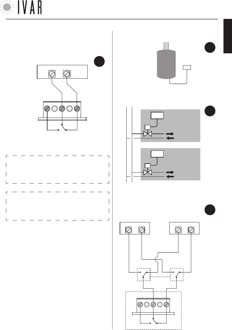
11) APPLICATION EXAMPLES
• application exam-
ple 1: boiler
• application example 2: zone valve
CHRONO
10) WIRING DIAGRAM
• electrical connection
• application example 3: plant with two generators for
WINTER/SUMMER operation.
FIG.
7
FIG.
8
FIG.
9
CHRONO
0=WINTER
1=SUMMER
0/1
C NO
NC
BOILER or ZONE
VALVE
CHILLER or ZONE
VALVE
FIG.
10
CAUTION: the operating logic of the system may re
-
sult in a time delay of about 15-20 minutes in the
activation of the boiler contact.
BOILER
or ZONE
VALVE
RELAY
NO
NC
C
CAUTION:
FOR THE US MARKET DO NOT CONNECT VOLTAGE
HIGHER THAN 24V ac/dc TO THE OUTPUT RELAY!
300546US-10-14
ENGLISH
ACTUATOR
[14]
FEATURES OF THE ACTUATOR
Each actuator (sold individually; provided separately
from the chronothermostat) physically controls the
radiator on which it is installed, guided by the chrono-
thermostat.
If you wish to improve the comfort level of a particu-
lar room or part thereof, there is also the possibility of
controlling each actuator immediately. In this way, maxi-
mum yield is obtained with accuracy and simplicity.
CONTENTS OF THE PACKAGE
• Actuator
• Utility key
• Stylus alkaline batteries
• Instructions sheet
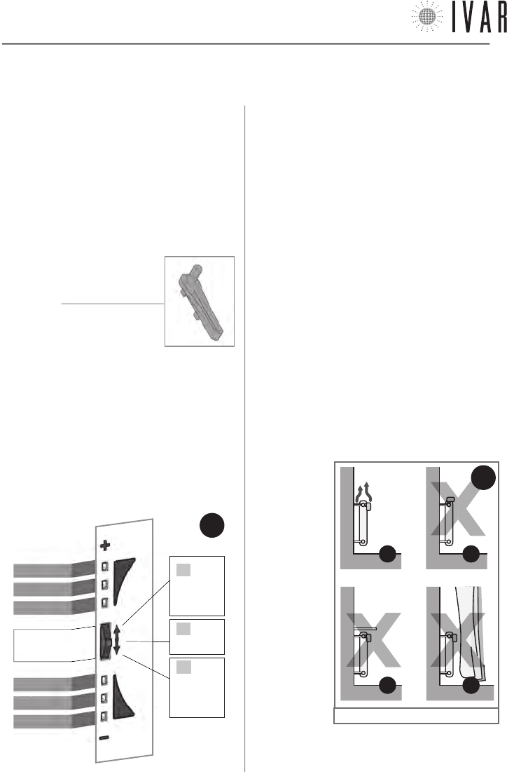
LED INDICATOR AND FRONT SELECTOR SWITCH
The actuator controls are found on the front side of the
device. They consist of:
• Led Indicator [LED from 1 to 6]
• Front selector [control key]
The front selector key operates in three positions:
A) Position ‘+’ (HIGH)
B) Position ‘SELECT’ (pressing the key)
C) Position ‘-‘ (LOW)
LED 1
LED 2
LED 3
LED 4
LED 5
LED 6
FRONT
SELECTOR
2. ATTUATORE
WARNINGS
1 .
During actuator installation, it is recommended that you
protect the toothed ring nut using a rag when tightening.
2 . When working with the actuator make sure it does
not come into contact with water and do not expose it to
high levels of humidity.
3 . The actuator options setup procedure should be
preferably be performed by the installer.
4 . It is important to verify that the batteries are work-
ing properly to prevent the heating/cooling system from
shutting down due to a lack of power to the actuator.
5 . Observe the following directions for using the bat-
teries: when it is time to dispose of them, place them
separately into the appropriate recycling container;
follow the installation instructions provided; avoid con-
necting the metal poles that are in contact with the
batteries in order to prevent a short circuit; always use
the type of batteries specified in this manual; do not
mix different batteries, old and new batteries or alkaline
batteries with standard or zinc coal batteries; the use
of rechargeable batteries results in less operating au-
tonomy when compared to non-rechargeable batteries.
6. If the device causes interference with other electrical
equipment, immediately remove them from the area.
7 . Do not dis-
pose of the
device in the
environment at
the end of its life
cycle. Dispose
of the device in
compliance with
current legisla-
tion.
8 . Follow the
directions in Fig-
ure-12 to posi-
tion the actuator.
ACTUATOR
CONTROLS
11
B*
11
A
11
D*
11
C*
FIG.
12
FIG.
11
B
PRESS
C
PUSH
DOWN-
WARDS
A
PUSH
UPWARDS
* See ‘Remote sensor’ on pg. 16
300546US-10-14

ACTUATOR
[15]
For help see ‘NAVIGATION MAP’ on pg. 22
CLOSING DISTANCE
( X )
MAX=
0.37 in
MAX= Ø0.83 in
M30x1,5
ENVIRONMENTAL CONDITIONS
• Temperature limits for transport and storage:
from -4 °F to +130 °F
• Operating temperature limits:
from 23 °F to +110 °F
5) BATTERY STORAGE CONDITIONS
• Temperature: 68 °F ensure long battery life
6) CONFORMITY
• Reference Standard (EMC): FCC 15 par. 15.247
7) SAFETY
• Type of insulation: CLASS III
8) OVERALL DIMENSIONS
• L=3.60 in, H=1.90 in, W=2.60 in
9) PRODUCT CODE
• Description: axial servomotor
• EQUICALOR-A: Art. AS 1000 Code 506364US
TECHNICAL CHARACTERISTICS OF THE ACTUATOR
1) TRANSMISSION
• Transmission frequency: 915.00 MHz
• Signal range: 33 yd with no obstacles
2) POWER SUPPLY
• Voltage: 4.5 V
• Type of batteries: 3 AA stylus alkaline batteries (mod.
LR6) 1.5V
• Battery life: 3 years (with brand new, well stored bat-
teries and in optimal operating conditions) *
• Type of device: Digital electronic
3) CONNECTION
• Type of connection: M30x1.5
• Closing distance ( X ): between 0.41 and 0.47 in
FCC ID: 2AB4Y506364US
This device complies with part 15 of the FCC Rules. Op-
eration is subject to the following two conditions: (1) this
device may not cause harmful interference, and (2) this
device must accept any interference received including
interference that may cause undesired operation.
NOTE: this equipment has been tested and found to
comply with the limits for a Class B digital device, pur-
suant to Part 15 of the FCC Rules. These limits are de-
signed to provide reasonable protection against harmful
interference in a residential installation. This equipment
generates, uses, and can radiate radio frequency energy
and, if not installed and used in accordance with the
instructions, may cause harmful interference to radio
communications. However, there is no guarantee that
interference will not occur in a particular installation.
If this equipment does cause harmful interference to
radio or television reception, which can be determined
by turning the equipment off and on, the user is encour-
aged to try to correct the interference by one or more of
the following measures:
• Reorient or relocate the receiving antenna.
• Increase the separation between the equipment and
receiver.
• Connect the equipment into an outlet on a circuit dif-
ferent from that to which the receiver is connected.
• Consult the dealer or an experienced radio/TV techni-
cian for help.
RF Exposure: this equipment complies with FCC ra-
diation exposure limits set forth for an uncontrolled
environment. This equipment should be installed and
operated with min. distance 20cm between the radiator
and your body. This transmitter must not be co-located
or operating in conjunction with any other antenna or
transmitter.
Warning: Changes or modifications to this device not
expressly approved by IVAR Spa could void the user’s
authority to operate the equipment.
*
battery life may be shortened by bad RADIO transmission conditions (L SIGN), by the presence of obstacles or by storage conditions other
than those prescribed. Batteries of different brands may have different behaviour and lower life than indicated in the present document.
300546US-10-14
ENGLISH
ACTUATOR
[16]
ROOM COMFORT TEMPERATURE ADJUSTMENT
With respect to the Set temperature for a single zone in
manual or automatic mode of the chronothermostat, it
is possible to make an immediate modification to a cer-
tain radiator using the front selector key of the actuator
concerned. For example, if two rooms are assigned to a
certain zone, you are given the opportunity to increase
or decrease the temperature present in either of these
up to about 6 °F; or, in the same way, to obtain the best
temperature for the room being used without having
to worry about editing the system’s programming (See
Table-1a).
The procedure described below applies only actuators
that are associated with areas other than Zone1.
Access the Room temperature adjustment function
keeping the front selector in the SE-
LECT position, until LEDs 3 and 4 light
up, which occurs after 5 seconds (See
Table at the side). Release the selec-
tor after this signal. The Led indicator
indicates the actual Room temperature
adjustment (See Table-1b).
To raise or lower the temperature by
approx. 2 °F simply touch ‘+’ or ‘-’ on
the selector. At each touch, the temperature is varied
within a total range that goes from approx. +6 °F to ap-
prox. -6 °F. If, for example, a zone is adjusted to value of
62 °F the room comfort of the individual actuator can go
from approx. 56 °F to 68 °F.
After having set the desired temperature, (see Table-
1b), a 5 second wait completes the procedure according
to the new setting.
Signal:
µ = Led on
Led 1 µ
Led 2 µ
Led 3 µ
Led 4 µ
Led 5 µ
Led 6 µ
OPEN
THIS
WAY
FIG.
13
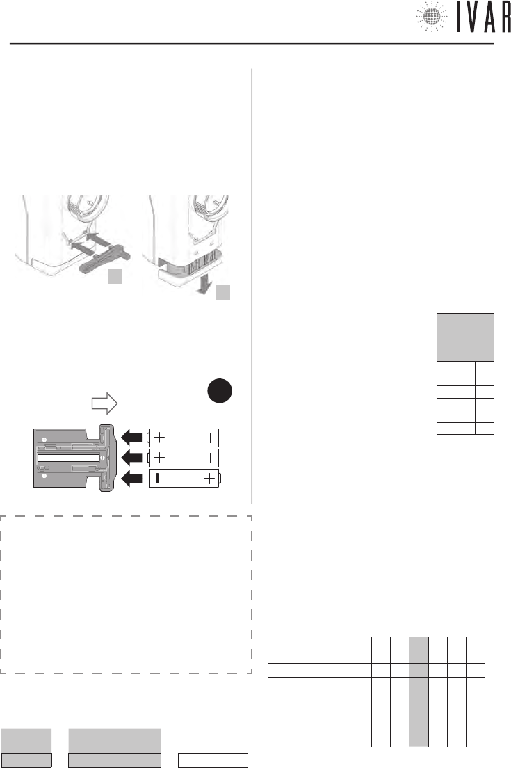
BATTERY REPLACEMENT
The actuator requires 3 AA 1.5 V Alkaline batteries.
The batteries must be inserted in order to operate the
equipment.
1) To replace the batteries, use the utility key, supplied
in the package.
2) Release the battery slide, inserting the utility key as
indicated in the figure.
3) Remove the battery housing slide and arrange the
batteries in the order and direction indicated on the bot-
tom of the slide (See Figure-13).
4) Reposition the slide, sliding it all the way until it clicks.
REMOTE SENSOR
(OPTIONAL)
It is possible to connect a remote room temperature
sensor (supplied as an optional - Art. AE 1000) to the
actuators, resulting in the exclusion of their built-in sen-
sors. The remote sensor allows detecting the tempera-
ture at a preset point, in case the actuator is installed in
an unfavorable position.
CAUTION: the remote sensor cannot be applied to the
actuators in ‘Zone1’.
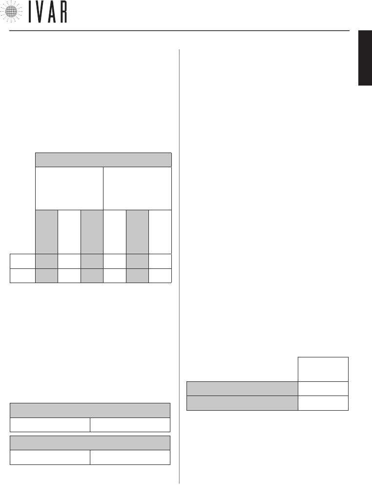
TABLE 1a
ROOM COMFORT TEMPERATURE (Example)
SET T. ROOM T. ADJUSTMENT ROOM COMFORT T.
64 °F + about 4 °F = about 68 °F
2
3
TABLE 1b
DEFINING THE ROOM TEMPERATURE ADJUSTMENT
temperature
adjustment à
-3 -2 -1 +0 +1 +2 +3
Led 1 µµµ µµµ
Led 2 µµµ µµµ
Led 3 µµµµµµ µ
Led 4 µµµµµµµ
Led 5 µµµ µ µ µ
Led 6 µµµ µµµ
NB µ = Led on
300546US-10-14
ACTUATOR
[17]
For help see ‘NAVIGATION MAP’ on pg. 22
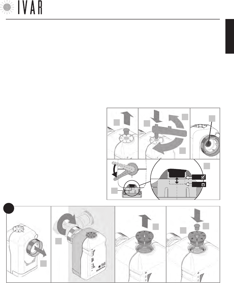
MANUAL RELEASE
If necessary, manually enable the emergency setting as
indicated below.
•
Remove the fixing pin from the numbered upper disc (2).
•
Press the utility key into the housing (3).
•
Release the actuator, slowly turning the utility key until
reaching the required position (4a/4b), as illustrated.
9) Put the numbered disc back in place, making sure the ‘0’
is aligned with the reference mark (*); then press the disc in
the housing.
10) Put the fixing pin back in place.
11) To complete the assisted closure/opening phase, the se-
lector must be kept in the SELECT position until Leds 3 and 4
light up, which happens after 5 seconds. Release the button
after this signal.
12) Proceed with associating the actuator and with the final
test. (See ‘Association of an actuator with the chronothermo-
stat’ in the chapter ‘TECHNICAL SECTION’).
INSTALLING THE ACTUATOR
1) Make sure to have installed the batteries (See
pg. 16).
2) Remove (with a small screwdriver) the fixing
pin from upper numbered disc as indicated in
the figure.
3) Press the utility key into the housing.
4) Fully open the actuator, slowly turning the
key anti-clockwise until about 45° from the limit
switch (4a), in order to align the piston (4c) with
the minimum point. This point is indicated in the
figure in detail 4d. Then remove the key.
5) Raise the connecting threaded ring nut in the
direction indicated.
6) Secure the actuator to the radiator manually
screwing down the threaded ring nut, tightening
it with an appropriate size wrench.
7) Fully close the actuator, maintaining the front
selector in position ‘-‘ until Led 4 flashes for the
first time (See Figure-11 on pg. 14), which oc-
curs after 5 seconds. Release the button after
this signal.
The simultaneous rapid flashing of Leds 4, 5, and
6 indicates closure has occurred.
8) Remove the numbered disc located on the up-
per part of the actuator (See figure).
The setting values are: ‘0‘ for maximum closure ‘6‘ for
maximum aperture. If the numeric scale is not correctly
positioned, fully close the actuator (turning the key
clockwise until the end of stroke) and then proceed as
indicated in steps 8 and 9 of the operations for Install-
ing the actuator (See pg. 17).
•
Remove the key and put the fixing pin back in place.
6*
910
5
8
FIG.
14
4c
3
4a
4b
2
4d
4c
MIN
MAX
300546US-10-14
ENGLISH
TECHNICAL SECTION
[18]
List of example alarms:
---Date------Time------ID----ERR---
10/02/11 07.00.00 Ch00 L BATT
03/02/08 11.10.21 Ac02 ERR MO
19/01/12 09.05.30 Ac03 L SIGN
12/01/10 05.22.59 Ac05 ERR TE
GENERAL OPERATION NOTES
The ambient temperature is detected directly on the
chrono for Zone 1 (Master) and on the actuators in Zones
2-8 (Slave). A patented algorithm allows correcting the
proximity effect that originates in Zones 2-8 due to the
proximity between the sensor and the heat source.
3. TECHNICAL SECTION
3.1
CHRONOTHERMOSTAT – SETUP
Access the Advanced Settings section (See ‘Menu Navi-
gation’ on pg. 6 for information about the control
keys) to adjust plant options depending on the specific
characteristics of the building (MENUàSETTINGSàAD-
VANCED SETINGS... this path will be indicated in this chap-
ter by an asterisk for the purpose of brevity).
During the access phase, respond to the system prompt
by selecting ENTER to proceed. The ‘Advanced Settings’
are listed below.
Limits
[
*àPLANTàLIMITSàWINTER
]
[
*àPLANTàLIMITSàSUMMER
]
To determine the maximum and minimum value of
each of the 6 temperature ranges that make up the
Winter set and Summer set, go to the Limits section
(For more information about the SETS, see Managing
the temperature sets on pg. 23). Select a value to
edit within the setting group chosen (Summer or Win-
ter) and press ENTER. Using the Up/down arrows, adjust
the value (maximum and minimum) corresponding to
Comfort-T1, Saving-T2 or Limit-T3. Then press ENTER.
Pre-activation (Max start up and shutdown anticipa-
tion)
[
*àPLANTàPRE-ACTIVATIONàMAX ANTICIPATION OF START UP
]
[
*àPLANTàPRE-ACTIVATIONàMAX ANTICIPAT. OF SHUTDOWN
]
Defines the maximum time limit that is calculated au-
tomatically by the chronothermostat for optimized sys-
tem start up/shutdown (MAX ANTICIPATION OF START UP/
MAX ANTICIPATION OF SHUTDOWN).
The time is expressed in minutes and can be changed
at increments of 1 minute. Use the Up/down arrows to
adjust and then press ENTER.
Pre-activation (Prestart savings reduction)
[
*àPLANTàPRE-ACTIVATIONàPRESTART SAVINGS REDUCTION
]
Modify this value to define the temperature drop
value obtained exiting the Comfort band when ‘SHUT-
DOWN OPTIMIZATION’ is enabled. This value is set by
default to 1 °F. Use
the Up/down arrows
to adjust and then
press ENTER.
Pre-activation (Comfort prestart index)
[
*àPLANTàPRE-ACTIVATIONSàCOMFORT PRESTART INDEX
]
Adjust this value
to set the prestart
comfort range
which the sys-
tem applies to the
function ‘START
UP OPTIMIZATION’.
The Index is set to 30 by default (10 = minimum, 60 =
maximum). A lower value minimizes the prestart, while
a greater value accentuates it. Use the Up/down arrows
to edit and then press ENTER.
Diagnostic (Stored Delta TPR)
[
*àPLANTàDIAGNOSTICSàSTORED DELTA TPR
]
Access to view the Delta TPR parameter, which is involved
in the controlling the zones. Press EXIT to go back.
Diagnostics (Alarm History)
[
*àPLANTàDIAGNOSTICSàALARM HISTORY
]
Access to view the chronological list of alarms (pre-
sent and past) reported by the system. Press EXIT to
go back. The list indicates the date and time in which
the problem was
detected, the ID
(identifier) of the
involved device
and the type of
problem (ERR).
The ID speci-
fies the type of
device the alarm concerns (CH=chronothermostat,
Ac=actuator) as well as its identification number. The
possible alarms (ERR) may include:
1) L BATT = Batteries discharged
2) L SIGN = Low radio communication capacity
3) ERR TE = Built-in or remote temperature sensor
failure (if installed).
4) ERR MO = Electric motor failure
NOTE: the errors 1, 2 and 3 are also indicated on the
actuators (See ‘Signals‘ on pg. 20).
Temperature
T1
Time
0.5
1.0
1.5
T2
Temperature
T1
Time
60 30 10
T2
300546US-10-14
TECHNICAL SECTION
[19]
For help see ‘NAVIGATION MAP’ on pg. 22
Diagnostic (Reset alarms)
[
*àPLANTàDIAGNOSTICàRESET ALARMS
]
To delete the alarm chronology, select ON, using the Up
arrow. The press ENTER to make the change.
Diagnostic (Enable diagnostics mode)
[
*àPLANTàDIAGNOSTICàENABLE DIAGNOSTICS MODE
]
To switch the chronothermostat to Test mode, select ON,
using the Up arrow. The press ENTER to make the change.
Enabling this function, battery consumption increases.
Diagnostics (Identify actuator)
[
*àPLANTàDIAGNOSTICSàIDENTIFY ACTUATOR
]
To identify a particular actuator, select an identification
number using the Up/down. Then press ENTER to start
the identification phase.
This operation may take a minute. Immediately after be-
ing identified the actuator corresponding to the number
selected will cause the Led indicator to flash.
Diagnostics (Identify zone)
[
*àPLANTàDIAGNOSTICSàIDENTIFY ZONE
]
The same procedure as the identification of an actuator,
it involves all devices in the selected zone (See ‘Identify
Actuator’).
User name
[
*àPLANTàUSER NAME
]
To identify the device controlled by the chronothermostat
and its associated zones, assign a name to this field. See
‘Zone names’ on pg. 8 for instructions.
Area settings
[
*àPLANTàAREA SETTINGS
]
If the conditions of transmission with the actuators are
favorable, it is possible to modify the capacity of the ra-
dio signal. To do this, access the Area settings section
and select Normal area with the Up/down arrows.
Number of managed zones
[
*àPLANTàNUMBER OF MANAGED ZONES
]
After providing further confirmation, the total number of
associated zones can be changed, and can include up to
a maximum of 8 zones.
NOTE: the bypassed zones can later be restored.
Reset the advanced settings
[
*àPLANTàADVANCED SETTINGS RESET
]
Enable this function when you intend to delete the
changes that have been made to the advanced settings.
A warning is prompted before you can proceed. Select
ON, using the Up arrow. Then press ENTER to make the
change.
Total device reset
[
*àPLANTàTOTAL DEVICE RESET
]
Through this option, it is possible to restore the chrono-
thermostat to its initial state, according to the factory
settings. After providing further confirmation, restore the
time bands and all the parameters. Select ON, using the
Up arrow. Then press ENTER to make the change. In this
way, all the data relative to the associated actuators and
all the options edited after installation will be cancelled.
To reuse the actuators you must carry out the associa-
tion operations, as indicated in the following chapter.
ASSOCIATION OF AN ACTUATOR WITH THE CHRONO-
THERMOSTAT
Each actuator requires a basic procedure for establishing
a connection with the chronothermostat which is defined
as ‘Association’. When the actuator is not associated, it
responds to each touch of the front selector with the
Signal A* (See ‘Signals’ in the following chapter). To start
transmission to the chronothermostat, use the controls
on the chronthermostat itself as follows. To begin, press
the MENU key and select Associations using the Up/down
arrows. Then press ENTER.
Select the desired zone from the menu list using the Up/
down arrows and then press ENTER (to customize the
names of the zones, see ‘Zone Names’ on pg. 8). Now
you can associate an actuator to the zone selected. En-
able the search function, maintaining the actuator’s front
selector in the SELECT position until Leds 2 and 5 light up,
which happens after 10 seconds. Release the button after
this signal. The search remains active for 5 minutes.
LED INDICATOR ILLUMINATION WHEN
FRONT SELECTOR IS PRESSED
Press
duration à
5
sec
10
sec
20
sec
30
sec
Led 1 µµµµ
Led 2 µµµ µ
Led 3 µµµµ
Led 4 µµµµ
Led 5 µµµ µ
Led 6 µµµµ
(µ = Led on)
Signal C* of the actuator defines the success of the
300546US-10-14
ENGLISH
TECHNICAL SECTION
[20]
operation (See ‘Signals’ on pg. 20). Now proceed with the
test; see the following paragraph.
Verifying correct association
When the association procedure is complete, on the chron-
othermostat carry out the ‘Identify actuator’ function. See
Diagnostics (Identify actuator) on pg. 19.
Managing the actuators
For correct system operation, the room in which the chron-
othermostat is installed MUST by defined as Zone1.
The system is able to manage up to a maximum of 28 ac-
tuators, which can be distributed in 8 zones. If one of the
actuators must be replaced, simply associate a new one
following the procedure described, up to a maximum of 4
replacements. If this new number of devices is reached,
carry out the procedure below before associating new ac-
tuators.
1) Perform ‘Total device reset‘.
2) Associate all the actuators (up to a maximum of 28).
3.2
ACTUATOR – SETUP
Signals
The types of signals that the Led Indicator can produce are
listed below:
LED INDICATOR: FLASHING SIGNALS
Type of signal àA* S* C* T1* T2*
Led 1 µµµµµ
Led 2 µµµµµ
Led 3 µµµµµ
Led 4 µµµµµ
Led 5 µµµµµ
Led 6 µµ µ µµ
• A* ACTIVE - rapid simultaneous flashing of the central
leds (LEDs 3 and 4), repeated 3 times.
• S* SEARCH - rapid movement of flashing from the centre
(LED 3 and 4) to the ends (LED 1 and 6), repeated 3 times.
•
C* CONFIRM - all leds flash for 1 second, repeated 3 times.
• T1* OPENING TEST - rapid simultaneous flashing of LEDs
1, 2 and 3 (repeated 3 times).
• T2* CLOSING TEST - rapid simultaneous flashing of LEDs
4, 5 and 6 (repeated 3 times).
• ANOMALY - in case of active alarms, the indicator com-
municates the following warnings at each touch of the
front selector. L BATT (Led 3 and 4 on) - L SIGN (Led 2 and
5 on) - ERR TE (Led 1 and 6 on). See ‘Diagnostics (Alarm
History)’ on pg. 18.
Options setup (selection and editing)
1) PARAMETER SELECTION (see Table-2)
To begin setting the parameters, maintain the front selec-
tor in the SELECT position until LEDs 1 and 6 which happens
after 20 seconds.
Release the button after this signal. Adjust the front selec-
tor in the ‘+’ or ‘-’ direction to scroll through the param-
eters from 1 to 6, indicated by the flashing led lights.
To proceed with setting the selected parameter, maintain
the selector in the SELECT position until Leds 3 and 4 light up,
which happens after 5 seconds. Release the key after this
signal (a period of 60 seconds of inactivity or pressing in po-
sition SELECT for 20 seconds, completes the programming).
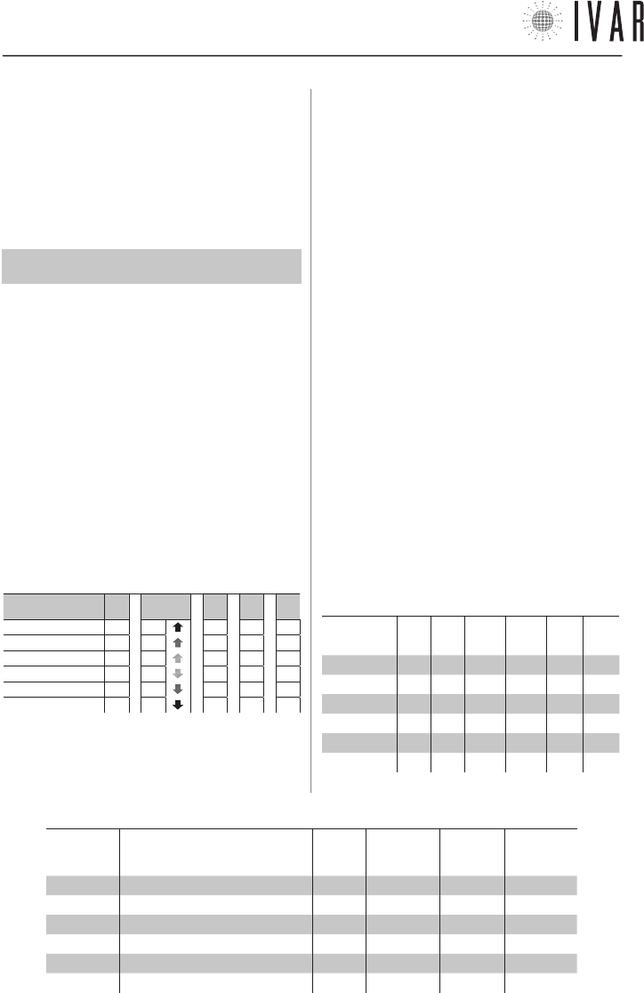
TABLE 2: PARAMETER SELECTION
Led flash-
ing Parameter Abbre-
viation Default Minimum Maximum
LED 1 (1) Service Srv C - -
LED 2 (2) Anti-condensation function Acd C - -
LED 3 (3) Hysteresis [°F] Ist 0.2 0.2 1.2
LED 4 (4) Maximum aperture Pmax 8 6 13
LED 5 (5) Corrective position Cp 3 2 7
LED 6 (6) Proportional coefficient Kp 0,10 0,01 0,20
TABLE 3: EDITING THE PARAMETERS
Parameter à(1)
Srv
(2)
Acd
(3)
Ist [°F]
(4)
Pmax
(5)
Cp
(6)
Kp
LED 1 - - 1.2 13 7 0,20
LED 2 - - 1.0 11 6 0,15
LED 3 - - 0.8 9 5 0,10
LED 4 A - 0.6 8 4 0,06
LED 5 B B 0.4 7 3 0,03
LED 6 C C 0.2 6 2 0,01
300546US-10-14
TECHNICAL SECTION
[21]
For help see ‘NAVIGATION MAP’ on pg. 22
2) EDITING A PARAMETER (see Table-3)
Adjust the front selector in the ‘+’ or ‘-’ direction to edit the
value of the previously selected, indicated by the fixed led
light. Then maintain the selector in the SELECT position for
5 seconds to confirm the selected value. The flashing of
LEDs 3 and 4 indicates the successful completion of the
procedure and the return to the parameters list. Therefore,
release the key. A period of 60 seconds of inactivity, without
making the change to the parameter being set, completes
the programming.
NOTE: the options setup can be run, even if the actuator has
not yet been associated with a chronothermostat.
PARAMETERS
1) Service
• A = Disassociation from chronothermostat
• B = Actuator reset
• C = No action (Default)
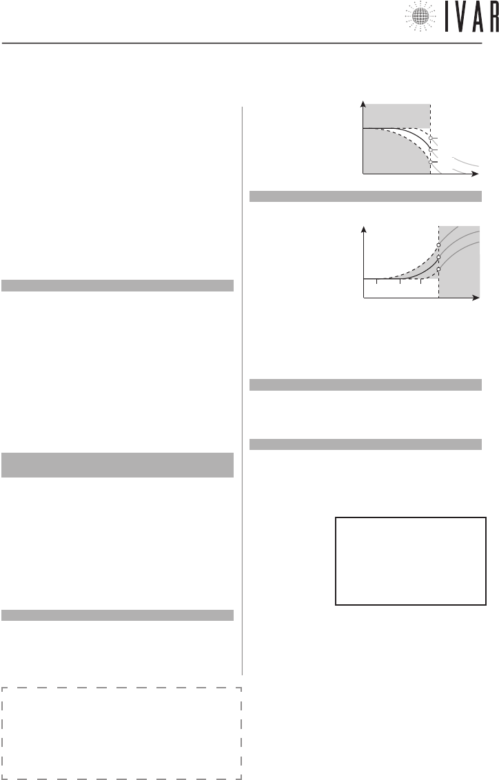
2) Anti-condensation
(See ‘Anti-condensation function’ on pg. 23.)
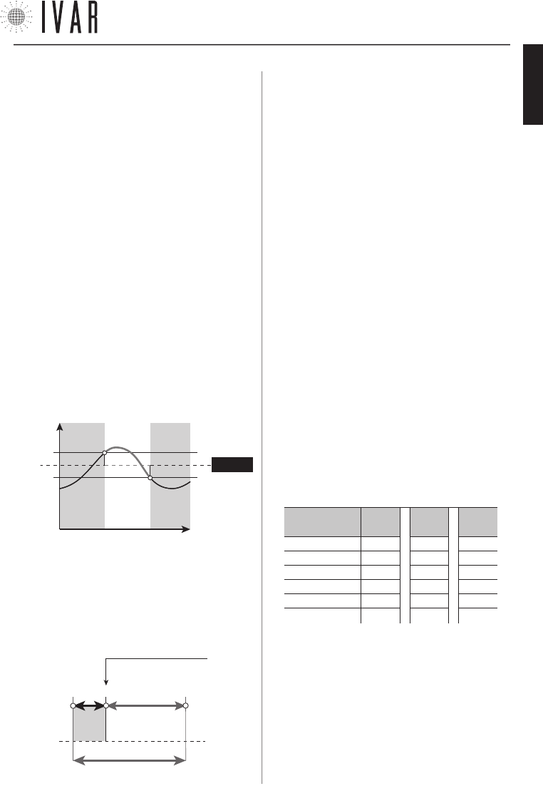
3) Hysteresis
This parameter is enabled only in ON/OFF operation and rep-
resents the positive/negative deviation from the set point,
useful for determining the closure/opening of the valve.
- Ist. SETPOINT
OPEN CLOSED OPEN
Temper-
ature
Time
+ Ist.
4) Pmax
Defines the proportional working band of the actuator.
5) Cp (Corrective position of the actuator)
Represents the theoretical point of valve closure (See
graph). Given the actuator effectively goes into overtravel
due to the elasticity of the rubber seal, the Cp allows the im-
mediate correction of this positioning in the opening phase.
Cp + Pmax
0* 3 12
Theoretical valve
closure point
Pmax=9
Cp=3
overtravel
* The ‘0’ closing position is found in a self-adapting manner
by the actuator.
6) Kp (Proportional coefficient)
The shifting of the actuator is proportional to the differ-
ence between the temperature required temperature and
the actual temperature. When Kp is increased smaller shifts
are obtained, while reducing Kp larger shifts are obtained.
Kp=0.01 (minimum value) results in ON/OFF operation.
Automatic opening/closing operation
A) To fully open the actuator, maintain the front selector in po-
sition ‘+‘ until Led 3 flashes for the first time, which occurs af-
ter 5 seconds. Release the button after this signal. Signal T1*
indicates opening has occurred (See ‘Signals’ on pg. 20).
Then press the selector in the SELECT position until Signal
A*, which occurs after 5 seconds. Release the button after
this signal, completing the operation.
B) To fully close the actuator, maintain the front selector in
position ‘-‘ until Led 4 flashes for the first time, which oc-
curs after 5 seconds. Release the button after this signal.
Signal T2* indicates closure has occurred.
Then press the selector in the SELECT position until Signal
A*, which occurs after 5 seconds. Release the button after
this signal, completing the operation.
Radio signal test
To check the quality of an actuator’s radio signal, maintain
the front selector in the SELECT position until the led indica-
tor’s luminous signal appears, after 30 seconds. The quality
level is indicated in Table-4.
TABLE 4: RADIO SIGNAL TEST
Signal quality à 2
(max)
1 0
(absent)
Led 1 µµ µ
Led 2 µµµ
Led 3 µµµ
Led 4 µµµ
Led 5 µµµ
Led 6 µµ µ
( NOTE: µ = Led on )
300546US-10-14
ENGLISH
NAVIGATION MAP
[22]
LIMITS
PRE-ACTIVATION
DIAGNOSTIC
USER NAME
NUMBER OF MANAGED ZONES
ADVANCED SETTINGS RESET
TOTAL DEVICE RESET
ADVANCED SETTINGS*
PLANT
MAX. SUMMER COMFORT T.
MIN. SUMMER COMFORT T.
MAX. SUMMER SAVING T.
MIN. SUMMER SAVING T.
MAX. SUMMER LIMIT T.
MIN. SUMMER LIMIT T.
WINTER
SUMMER
MAX. ANTICIPATION OF START UP
MAX. ANTICIPATION OF SHUTDOWN
PRESTART SAVINGS REDUCTION
COMFORT PRESTART INDEX
STORED DELTA TPR
ALARMS HISTORY
RESET ALARMS
ENABLE DIAGNOSTICS MODE
IDENTIFY ACTUATOR
IDENTIFY ZONE
AREA SETTINGS
MAX. WINTER COMFORT T.
MIN. WINTER COMFORT T.
MAX. WINTER SAVING T.
MIN. WINTER SAVING T.
MAX. WINTER LIMIT T.
MIN. WINTER LIMIT T.
CURRENT LANGUAGE
WINTER SET
SUMMER SET
ZONES/SUMMER ADJUSTMENT
WINTER/SUMMER MODE
DATE
TIME
TIME FORMAT
TEMPERAT. MEASUREMENT UNITS
CONTRAST
BRIGHTNESS
START UP OPTIMIZATION
SHUTDOWN OPTIMIZATION
SET ZONE NAMES
MODE
SETTINGS
ASSOCIATIONS
PREFERENCES
MANUAL MODE
AUTOMATIC MODE
SHUTDOWN MODE
SET TIME
DAYLIGHT S. TIME
SET WINTER COMFORT
SET WINTER SAVING
SET WINTER LIMIT
SET SUMMER COMFORT
SET SUMMER SAVING
SET SUMMER LIMIT
ENABLE MANUAL MODE
MAN. FOR 1 HOUR
MAN. FOR 2 HOURS
SET DURATION OF M. MODE
SHUTDOWN
SHUTDOWN FOR 1 HOUR
SHUTDOWN FOR 2 HOURS
SET SHUTDOWN DURATION
ENABLE AUTOMATIC MODE
12 HOUR FORMAT
24 HOUR FORMAT
ZONE 1
ZONE 1 NAME
ZONE 1
M/T/W/T/F/S/S
SCHEDULE GRAPH
ZONE 1 ASSOCIATION
M
A
I
N
M
E
N
U
KEY LOCK
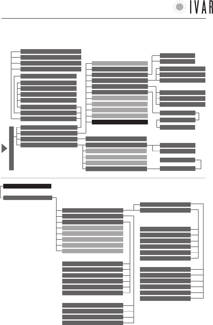
ADVANCED SETTINGS*
FUNCTION NAVIGATION MAP: starting from the chronothermostat’s main MENU (indicated by the arrow in the fig-
ure), accessed by pressing the MENU button, follow the diagram shown on this page to reach the desired section.
300546US-10-14
APPENDIX
[23]
Specifications and documentation are subject to change without prior notice by the manufacturer.
TABLE 5: TEMPERATURE RANGES (Default)
WINTER
SET
SUMMER
SET
COMFORT
SAVING
LIMIT
COMFORT
SAVING
LIMIT
T MAX 77 °F 68 °F 59 °F 86 °F 95 °F
104 °F
T MIN 59 °F 50 °F 41 °F 68 °F 77 °F 86 °F
MANAGING THE TEMPERATURE SETS
Guide to setting
Refer to the following instructions to manage the tem-
perature sets (‘Winter Set’ and ‘Summer Set’)
The total range of the temperatures is divided into 6
specific intervals, as illustrated in Table-5.
The following example indicates a possible way of set-
ting T1-T2-T3 in ‘Winter mode’:
• Define a COMFORT temperature of 66 °F for the Set
winter comfort (T1) option.
• Next define a SAVING temperature between 50 °F and
66 °F for the option Set winter saving (T2). T2, as a mat-
ter of fact, is dependent on T1; for example set 58 °F.
• T3 is in turn dependent on T2 and, in this specific case,
for the Set winter limit (T3) option it is possible to set a
LIMIT temperature between 41 °F and 58 °F.
INTERACTION BETWEEN THE RANGES (WINTER)
COMFORT>SAVING SAVING>LIMIT
INTERACTION BETWEEN THE RANGES (SUMMER)
COMFORT<SAVING SAVING<LIMIT
When necessary it is also possible to redefine the maxi-
mum and minimum values for each of the 6 tempera-
ture ranges. For example:
1) Access MENUàSETTINGSàADVANCED SETTINGSàPLANTà
LIMITSàWINTERàMINIMUM WINTER COMFORT TEMP.
and set a
value of 68 °F. Then press ENTER.
2) Access
MENUàSETTINGSàADVANCED SETTINGSàPLANTà
LIMITSàWINTERàMAXIMUM WINTER COMFORT TEMP.
and set a
value of 80 °F. Then press ENTER. In this way, a COMFORT
range (12 °F of extension) that goes from 68 °F to 80
°F is obtained. It is important to note that each range
must have an extension of at least 3 °F (approx.). If, as
a matter of fact, we set 70 °F as the MAXIMUM WINTER
COMFORT TEMP. value, the system will automatically set
the MINIMUM WINTER COMFORT TEMP. value to 67 °F. The
new COMFORT range (approx. 3 °F of extension) will go
from 67 °F to 70 °F.
ANTI-CONDENSATION FUNCTION ADJUSTMENT
When installing the actuators, it may be necessary to ac-
tivate the anti-condensation function on some devices;
this is enabled using the controls on the actuator itself.
A possible case is the need to exclude a decorative ra-
diator from summer operation.
To modify this function, set Parameter 2 (Acd) of the
actuator as indicated in Table-6 (See ‘Actuator options
setup’ on pg. 20 for further details):
TABLE 6 VALUE OF ‘Acd’
PARAMETER
ANTI-CONDENSATION FUNCTION ON B
ANTI-CONDENSATION FUNCTION OFF C
NOTE: the anti-condensation is disabled by default
300546US-10-14
ENGLISH
1. CRONOTERMOSTATO
Características del cronotermostato p. 25
Contenido de la caja p. 25
Pantalla y teclas de mando p. 25
Advertencias p. 26
Lista de las alarmas p. 26
Condiciones de garantía del cronotermostato p. 26
Contactos p. 26
Instalación/Sustitución de las pilas p. 27
Modos operativos p. 27
Configuración del cronotermostato p. 28
Configuración automática de la temperatura p. 31
Instalación del cronotermostato p. 32
Características técnicas del cronotermostato p. 34
2. ACTUADOR
Características del actuador p. 36
Contenido de la caja p. 36
Indicador led y selector frontal p. 36
Advertencias p. 36
Características técnicas del actuador p. 37
Instalación/Sustitución de las pilas p. 38
Sensor remoto p. 38
Regulación de la temperatura confort local p. 38
Instalación del actuador p. 39
Desbloqueo manual p. 39
3. SECCIÓN TÉCNICA
3 . 1 (CRONOTERMOSTATO)
Cronotermostato - setup p. 40
Asociación de un actuador con el cronotermostato p. 41
3 . 2 (ATTUATORE)
Actuador – setup p. 42
4. MAPA DE NAVEGACIÓN DE LAS FUNCIONES p. 44
5. APÉNDICE p. 45
ÍNDICE
INSTALACIÓN DEL SISTEMA EQUICALOR
1) Identificar las zonas
Planificar la subdivisión de la vivienda en zonas, determi-
nando su cantidad.
2) Definir una posición para el cronotermostato
El cronotermostato detecta la temperatura del ambiente y
debe estar colocado en una posición donde haya buena cir-
culación de aire, a 5 ft del suelo. Ver Posicionamiento típico
del aparato en la pag. 32.
3b) Instalar el cronotermostato en la pared
Fijar el cronotermostato en la posición establecida y ejecutar la
conexión a la caldera. Ver Instalación a la pared en la pag. 33.
¡ATENCIÓN! Asegurarse de excluir la tensión de red del
sistema eléctrico antes de realizar dicho procedimiento.
4) Colocar las pilas en el cronotermostato.
El cronotermostato usa n. 3 pilas alcalinas AA 1,5V. Para in-
troducir las pilas, ver Instalación/sustitución de las pilas de
la pag. 27.
5) Configurar idioma, fecha y hora
Introducir los datos para el primer encendido, como se indi-
ca en los apartados Idioma actual, Fecha y Hora (Configurar
hora) de la pag. 29. Para utilizar el teclado de mando, ver
Configuración del cronotermostato y Navegación del menú
en la pag. 28.
6) Configurar las zonas
Configurar el número de zonas de la vivienda, como se indi-
ca en el apartado Número de zonas gestionadas en la pag.
41. Para acceder a dicha función, ver Configuración del
cronotermostato en la pag. 28.
7) Colocar las pilas en el actuador
El actuador usa n. 3 pilas alcalinas AA 1,5V. Para introducir
las pilas, ver Instalación/sustitución de las pilas de la pag.
38.
8) Instalar el actuador
Montar los actuadores en los respectivos radiadores. Ver
Instalación del actuador en la pag. 39.
9) Asociar todos los actuadores al cronotermostato y rella-
marlos para su verificación
Ver el capítulo ‘Asociación de un actuador con el cronoter-
mostato‘ en la pag. 41.
GUÍA RÁPIDA
300546US-10-14
CRONOTERMOSTATO
[25]
Para ayuda ver ‘MAPA DE NAVEGACIÓN’ de la pag. 44
INTRODUCCIÓN
El sistema EQUICALOR está compuesto por un
cronotermostato y actuadores integrados de zona.
El cronotermostato puede controlar su sistema
gestionando la termorregulación.
Los actuadores se instalan directamente en los
radiadores, para ejecutar en cada local la regulación del
funcionamiento.
Tanto en la función de calentamiento como en aquella
de refrigeración EQUICALOR garantiza una temperatura
ideal del ambiente y el ahorro energético en los períodos
del día donde los locales están ocupados.
Las informaciones contenidas en este manual
contribuirán a simplificar la personalización del sistema
y la reducción de costes de ejercicio del sistema.
1. CRONOTERMOSTATO
PANTALLA Y TECLAS DE MANDO
Las Teclas de mando están compuestas por:
• Tecla multifunción derecha (1)
• Tecla multifunción izquierda (5)
• Tecla ‘reset’ (2)
• Cuatro flechas de navegación (3)
• Botón ’OK-MODE’ (4)
NOTA: Si el bloqueo teclas no está activado, el primer toque del
teclado tiene la función de ponerlo en funcionamiento.
TECLAS DE
MANDO
PANTALLA
*temperaturas:
T1=T confort
T2=T ahorro
T3=T límite
(L)
(I)
(3)(4)
(1)
(5)
(B) (M)
(C)
(2)
(A)
(H)
(G)
(F)
(D) (E)
(D1)
La Pantalla presenta los siguientes campos:
• Icono flechas de navegación (A)
• Campo de la tecla multifunción izquierda: ‘MENÚ/
SALIR/ANULAR (B)
• Gráfico Horario 7-DÍAS (C) con franjas T1, T2,
T3 (ver nota de abajo*)
• Modalidad activa (D)
• Modalidad temporal en funcionamiento (D1)
• Temperatura configurada (E)
• Zona corrientemente seleccionada (F)
• Temperatura detectada <solo ZONA1> (G)
• Modalidad INVIERNO , Modalidad VERANO y
Promemoria Alarma (H)
• Fecha (I) y Hora (L)
• Campo de la tecla multifunción derecha: ’ENTRAR/
MODIFICAR/CONFIRMAR/VISUALIZAR/SOLAR (M)
• Cronotermostato • Pilas alcalinas estilo • El presente manual de uso
CONTENIDO DE LA CAJA
CARACTERISTICAS DEL CRONOTERMOSTATO
El cronotermostato EQUICALOR-AC puede gestionar de
modo independiente cada ambiente, controlando hasta
8 zonas. También permite el control directo de la
caldera de pared.
300546US-10-14
ESPAÑOL
CRONOTERMOSTATO
[26]
ADVERTENCIAS
1. La regulación de las configuraciones avanzadas del
cronotermostato debe encomendarse preferiblemente
al instalador.
2. Es importante verificar la plena eficiencia de las pilas
para prevenir la parada del sistema de calefacción/
refrigeración debidos a la ausencia de alimentación del
cronotermostato.
3. Sujetarse a las siguientes indicaciones para el
empleo de las pilas: cuando fuera necesario eliminarlas,
tirarlas separadamente en el contenedor de recogida
diferenciada; sujetarse a las instrucciones de
instalación proporcionadas; cuando el dispositivo está
en inactividad por un período prolongado de tiempo,
quitar las pilas; evitar conectar los polos metálicos
que se encuentran en contacto con las pilas para no
causar un cortocircuito; usar siempre el tipo de pilas
especificado en el manual; no mezcle pilas diferentes,
viejas con nuevas o pilas alcalinas con pilas estándar
de cinc-carbón; el empleo de pilas recargables implica
una menor autonomía de funcionamiento respecto a las
pilas no recargables.
4. Si el dispositivo provocara interferencias con otros
aparatos eléctricos, alejarlos inmediatamente.
5. Al final del ciclo de vida del aparato, no dispersarlo en
el ambiente. Eliminarlo respetando las leyes vigentes.
6. El montaje del cronotermostato debe realizarse
exclusivamente por personal autorizado de conformidad
con las normas y leyes vigentes; en ausencia de tensión
de red.
7. La ‘Lista de las alarmas’ aparece al encenderse la
pantalla en caso de posibles anomalías. Ver el apartado
siguiente.
CONDICIONES DE GARANTÍA DEL CRONOTERMOSTATO
I.V.A.R. S.P.A está asegurada por daños ocasionados
a terceros por defecto de fabricación constatado de
los productos, en los términos y límites enunciado en
el Decreto Legislativo 206/2005. La cobertura máxima
de seguro de € 3.000.0000 por siniestro y por año. La
responsabilidad de IVAR por los daños de productos
defectuosos está disciplinada por las condiciones
generales de venta y por el decreto legislativo 206/05
(art 114-127) y se extiende por 2 años desde la
instalación del producto.
I.V.A.R. S.p.A. garantiza la conformidad y el buen
funcionamiento de sus productos en los términos
citados por el decreto legislativo n. 206/05.
LISTA DE LAS ALARMAS
Si se presenta un problema de funcionamiento, el si-
stema mantiene un rastro de la anomalía. Si el error
persiste, una aviso aparece al primer encendido de la
pantalla. Este mensaje puede consultarse en cualquier
momento en la sección ‘Historial alarmas’ para conocer
los detalles (Ver el relativo apartado en la pág. 40).
La ruta a seguir para poder acceder es el siguiente:
MENÚàCONFIGURACIONESàCONFIGURACIONES AVANZADASàIN-
STALACIÓNàDIAGNOSTICOàHISTORIAL ALARMAS
NOTA: el icono Promemoria Alarma ’ ’ aparece en caso
de error y permanece activa hasta la apertura del ’HI-
STORIAL’.
CONTACTOS
IVAR US, Inc.
Dirección postal: PO Box 8015, Elkridge, MD 21075
T:1-855-9-IVAR-US
www.ivar-us.com
info@ivar-us.com
I.V.A.R. S.p.A.
Via IV Novembre, 181
25080 Prevalle (BS) - Italy
T: +39 030 68028 - F: +39 030 6801329
www.ivar-group.com
info@ivar-group.com
300546US-10-14
CRONOTERMOSTATO
[27]
Para ayuda ver ‘MAPA DE NAVEGACIÓN’ de la pag. 44
B1 B2
B3
FIG.
2
NOTA: Al primer encendido la pantalla propone la
selección del idioma, de la hora y la fecha; el idioma
predeterminado es el inglés (para completar dicho
procedimiento, ver Navegación del menú’ en la pág.
28. En dicho apartado se ilustra el uso del teclado de
mando).
La alarma de pilas descargadas (L BATT) señala que
la alimentación de las pilas está casi terminada y el
funcionamiento continuará en programa antihielo por
unos 15 días hasta su agotamiento; sustituirlas para
restablecer su operatividad. Para mayores detalles
sobre las alarmas, ver ‘Diagnóstico (Historial alarmas)’
de la pag. 40; las alarmas pueden referirse al
cronotermostato o a los actuadores. La extracción de
las pilas no produce la pérdida de las configuraciones
definidas.
Para colocar o sustituir las pilas, abrir la compuerta
anterior del cronotermostato (Ver Figura-1). Después
colocar las pilas en sus asientos (B1, B2, B3), teniendo
cuidado de colocarlas en le sentido indicado en el fondo
de cada alojamiento (Ver Figura-2).
INSTALACIÓN/SUSTITUCIÓN DE LAS PILAS
El cronotermostato usa n. 3 pilas alcalinas AA 1,5V. Se
deben colocar las pilas para que el aparato funcione.
MODOS OPERATIVOS
El cronotermostato puede trabajar en tres modalidades
diferentes: modo Automático, Manual y Apagado. El
icono Modalidad activa nos indica cuál de éstas tres
está actualmente en funcionamiento. Para activar la
pantalla, tocar cualquier tecla. En el funcionamiento
normal del cronotermostato la pantalla ilustra durante
30 segundos las informaciones sobre el estado del
sistema relativas al modo activo. (En el funcionamiento
‘Modo automático’ el icono Zona corrientemente
seleccionada especifica la zona a la cual se refieren
dichas informaciones. Para obtener una reseña de cada
una de las zonas, usar las flechas Izquierda/derecha).
Para pasar de una modalidad a la otra, presionar
OK-MODE reiteradamente hasta visualizar el modo
requerido.
Modo Manual
[MENÚàMODALIDADàMODO MANUALàACTIVAR MODO MANUAL]
Define una temperatura fija que se mantendrá en todas
las zonas (TEMPERATURA CONFIGURADA).
Las teclas Arriba/abajo (flechas de navegación)
modificar el valor de la Temperatura configurada,
aumentándola o disminuyéndola de 1 °F. El paso a otra
modalidad interrumpe el modo Manual.
Modo apagado
[MENÚàMODALIDADàMODO APAGADOàAPAGAR]
El modo apagado desactiva el sistema, pasando a
la función antihielo. Dicho programa garantiza una
temperatura ambiente mínima de 41 °F para preservar
la instalación. En la pantalla se puede leer la fecha, hora
y temperatura detectada. Además, se puede acceder al
menú.
NOTA: para retener el modo manual o el modo apagado para un
FIG.
1
1
300546US-10-14
ESPAÑOL
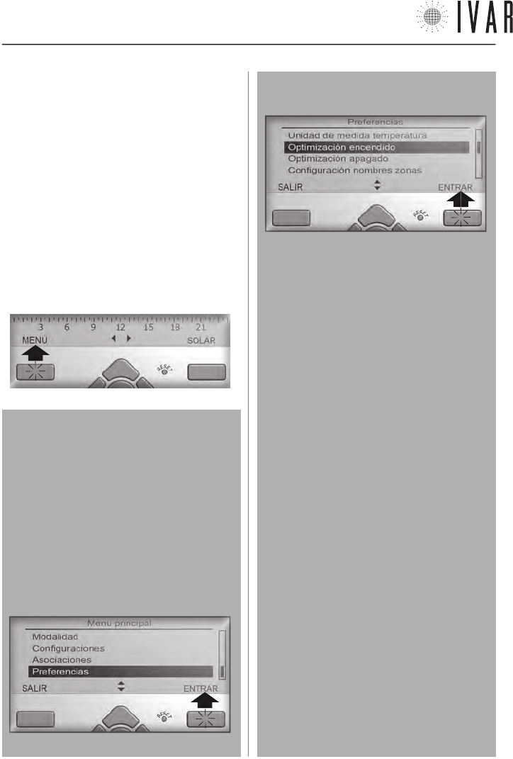
CRONOTERMOSTATO
[28]
Para iniciar, presionar la tecla multifunción
izquierda.
período de tiempo definido, ver el apartado ‘Configura-
ción automática de la temperatura’ de la pag. 31.
Modo Automático
[MENÚàMODALIDAD
àMODO AUTOMÁTICOàACTIVAR MODO AUTOMÁTICO]
Para informaciones sobre esta modalidad, ver pag. 31.
CONFIGURACIÓN DEL CRONOTERMOSTATO
Para configurar las opciones del cronotermostato se
debe acceder al MENÚ. Si la pantalla está apagada, ac-
tivarla presionando cualquier tecla. Presionar la Tecla
multifunción izquierda como se ilustra para ver la lista
de secciones.
Navegación del menú
Seleccionar con las teclas Arriba/abajo (flechas
de navegación) el campo requerido. Presionar OK
o la Tecla multifunción derecha para entrar en la
opción evidenciada. Algunas opciones avanzadas
requieren otra CONFIRMACIÓN, antes de continuar.
En el encabezamiento está indicado el nombre de la
página para facilitar la navegación.
El ejemplo siguiente ilustra el procedimiento de
acceso a la opción ‘Optimización encendido’.
1 - desplazar la lista con las TECLAS ARRIBA/ABAJO
para seleccionar ‘Preferencias‘ y por último, presio-
nar la Tecla multifunción derecha para acceder.
2 - desplazar la lista con las TECLAS ARRIBA/ABAJO para
seleccionar ‘Optimización encendido‘ y presionar la Te-
cla multifunción derecha para iniciar la modificación.
En las diferentes operaciones de modificación de las
opciones, las Teclas multifunción permiten proceder
paso a paso para completar dichos procedimientos.
Ver la lista siguiente (Se aconseja saber que, si no
se opera en los mandos por más de 30 segundos, el
sistema apaga la pantalla, abandonando la consulta
del menú).
Lista de las funciones de los botones
(teclas multifución o teclas flecha)
• ENTRAR para acceder a una sección.
• MODIFICAR para iniciar un procedimiento.
• CONFIRMAR para concluir un procedimiento ejecu-
tando la modificación.
• VISUALIZAR para consultar una página.
• SALIR para abandonar una sección.
• ANULAR para volver atrás sin concluir la modifica-
ción en curso.
• SOLAR/LEGAL para ejecutar el cambio de hora.
• Arriba/abajo (flechas de navegación) para navegar
una lista o modificar un valor de temperatura, fe-
cha, hora. Usando las flechas, mantener presiona-
do para modificar más rápidamente.
• Izquierda/derecha (flechas de navegación) para
pasar de un campo de valor al otro.
NOTA: ver el ‘Mapa de navegación de las funciones’
de la pág. 44 para la lista completa de las seccio-
nes de menú y la relativa ruta de acceso.
NOTA: al inicio de las descripciones de cada función
se indica la ruta a seguir para poder acceder, por
ejemplo: [MENÚàCONFIGURACIONESàIDIOMA ACTUAL].
300546US-10-14
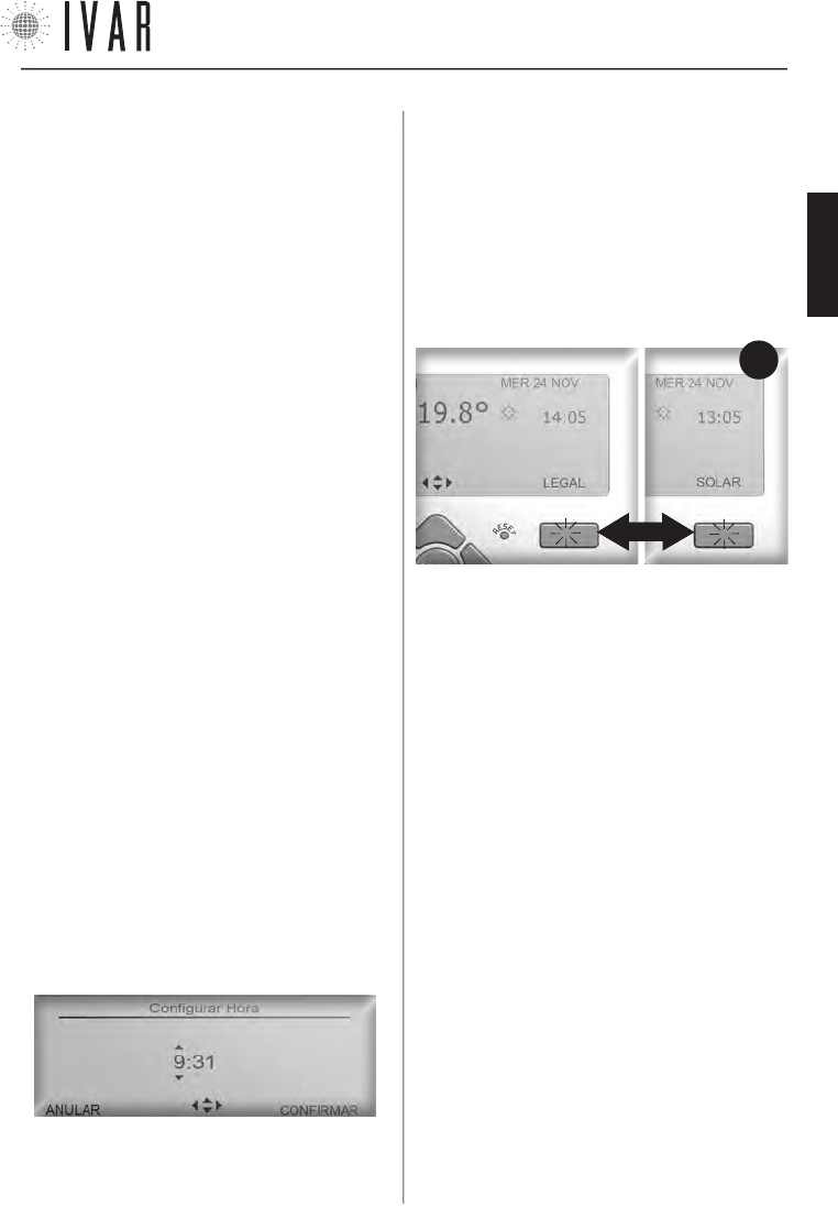
CRONOTERMOSTATO
[29]
Para ayuda ver ‘MAPA DE NAVEGACIÓN’ de la pag. 44
Hora (Hora legal)
[MENÚà CONFIGURACIONESàHORAàHORA LEGAL]
Acceder a la sección Hora legal para gestionar el cambio
de la hora. Usasr las flchas Arriba/abajo para modificar
la configuración. Seleccionar ON para activar el cambio
de la hora, o presionar OFF para mantener la hora solar
durante todo el año. Al final, presionar CONFIRMAR. De-
spués de haber activado el cambio de la hora, la pantalla
indicará en el funcionamiento normal el tipo de hora
activa (ver Figura-3).
Cada presión de la Tecla multif. derecha, este caso eje-
cuta el cambio de hora solar y legal y viceversa, permi-
tiendo actualizar el reloj en la fecha establecida.
Programación invierno, Programación verano, Zonas,
Regulación verano, Modalidad verano/invierno
[MENÚàCONFIGURACIONESà...]
Ver pag. 31.
Regulación contraste y luminosidad
[MENÚàCONFIGURACIONESàCONTRASTE]
[MENÚàCONFIGURACIONESàLUMINOSIDAD]
Determinan el contraste de la pantalla y la luminosidad
de la retroiluminación. Usar las flechas Arriba/abajo para
seleccionar una regulación nueva, presionar CONFIRMAR.
La configuración predeterminada de la luminosidad está
al ‘Mínimo’ que garantiza la duración ideal de las pilas.
Bloqueo teclas
[MENÚàCONFIGURACIONESàBLOQUEO TECLAS]
Acceder a la sección Bloqueo teclas para encender y
apagar esta función.
1) Seleccionar ON, usando las flechas Arriba/abajo
para proteger el dispositivo de las modificaciones
accidentales. Después, presionar CONFIRMAR. En este
caso, cuando no opere en el teclado por 30 segundos, la
pantalla suspende la iluminación y el teclado se bloquea.
FIG.
3
CONFIGURACIONES- ASOCIACIONES - PREFERENCIAS
Sigue una lista de las secciones del menú.
Reset [TECLA ‘reset’]
Si se verifica un comportamiento atípico, volver a
encender el dispositivo. Para ello, presionar con un lápiz
o un ganchito el botón Reset en el teclado de mando.
NOTA: con esta operación NO se pierden las
configuraciones que han sido definidas anteriormente.
Idioma actual
[MENÚàCONFIGURACIONESàIDIOMA ACTUAL]
El cronotermostato prevé el uso de 9 idiomas (italiano,
inglés, francés, alemán, español, portugués, flamenco,
checo, noruego). Acceder a la sección Idioma actual (Ver
‘Navegación del menú’ de la pag. 28).
Para modificar la opción idioma, usar las flechas Arri-
ba/abajo y seleccionar en la lista el idioma requerido.
Presionar CONFIRMAR para terminar el procedimiento.
Fecha
[MENÚàCONFIGURACIONESàFECHA]
Acceder a la sección Fecha para regular el día actual (Ver
‘Navegación del menú’ en la pag. 28). Usar la tecla
Izquierda/derecha para pasar desde la regulación ‘día’ a
la regulación de ‘mes’ o ‘año’. Después presionar Arriba/
abajo para cambiar día/mes/año de una unidad. Presio-
nar CONFIRMAR para concluir el procedimiento o ANULAR
para dejar el procedimiento y volver sin aportar cambios
al menú anterior.
Hora (Configurar hora)
[MENÚàCONFIGURACIONESàHORAàCONFIGURAR HORA]
Acceder a la sección Configurar hora para regular el ho-
rario actual (Ver ‘Navegación del menú’ en la pag. 28).
Usar la tecla Izquierda/derecha para pasar desde la re-
gulación ‘horas’ a la regulación de ‘minutos’ y viceversa.
Después presionar Arriba/abajo para cambiar horas/
minutos de una unidad. Presionar CONFIRMAR para ter-
minar el procedimiento.
300546US-10-14
ESPAÑOL
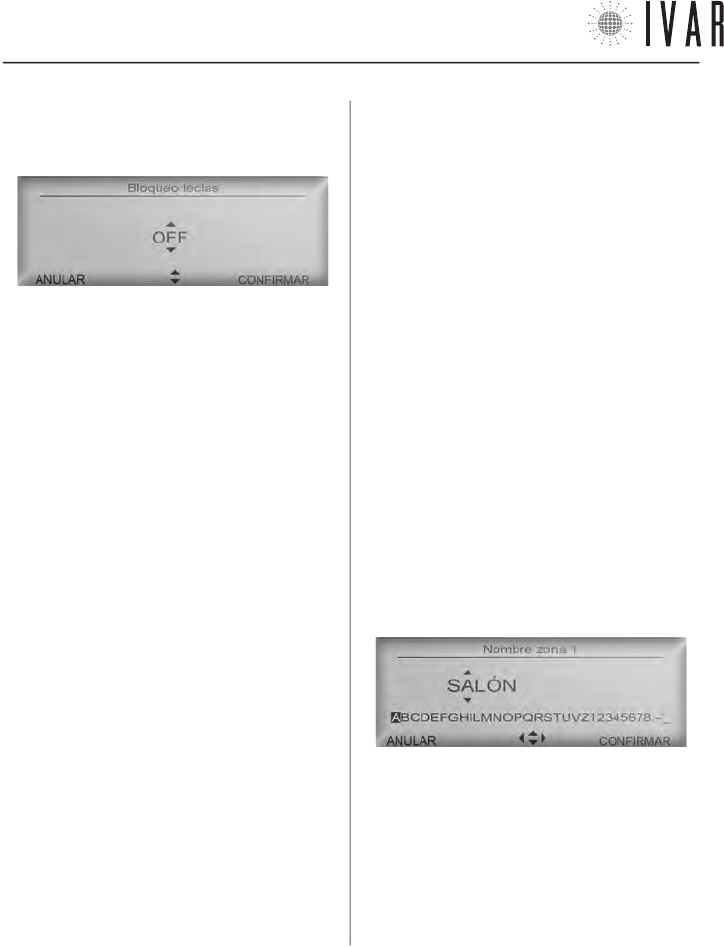
CRONOTERMOSTATO
[30]
Con cada toque sucesivo del teclado, la pantalla se
ilumina para 10 segundos e indica la tecla a presionar
para el desbloqueo.
activa la optimización y OFF la desactiva. Usar las flechas
Arriba/abajo para modificar la configuración, presionar
CONFIRMAR.
El proceso de optimización se autorregula y su precisión
en el funcionamiento normal se afina con el paso de
los días, mejorando sus prestaciones. Si la Optimización
encendido está activa, se anticipa el encendido de modo
tal de poder alcanzar realmente la temperatura de
Confort en el momento preciso que ha sido establecido
en la programación. Análogamente, la Optimización
apagado (si está activa) anticipará el apagado de modo
tal de tener en la entrada en la franja T2 una temperatura
optimizada Ts (Ts=T1-Tred con Tred equivalente al valor
de la Reducción prestart ahorro).
Nombres zonas
[MENÚàPREFERENCIASàCONFIGURAR NOMBRES ZONAS]
Permite personalizar la denominación de cada zona.
Para iniciar, seleccionar una zona por medio de las
flechas Arriba/abajo y después presionar CONFIRMAR.
Utilizar las flechas Arriba/abajo para modificar una
letra y las flechas Izquierda/derecha para pasar a las
letras siguientes. Seguir las indicaciones de la ‘Barra
de desplazamiento de los caracteres’ que está bajo el
nombre para redactar el texto.
2) Seleccionar OFF para anular la protección y sucesi-
vamente presionar CONFIRMAR. En este caso, con cada
toque del teclado la pantalla se ilumina hasta el siguien-
te apagado, que se produce después de 30 segundos
de inactividad.
Asociaciones
[MENÚàASOCIACIONES]
Ver el apartado ‘Asociación de un actuador con el
cronotermostato‘ en la pag. 41.
Formato hora (12, 24)
[MENÚàPREFERENCIASàFORMATO HORA]
Cambiando esta opción, el campo horario estará
expresado en el formato 24 (Ej: 18:25) y no en el
formato 12 (Ej: 6:25 PM). Usar las flechas Arriba/abajo
para configurar la opción. Al final, presionar CONFIRMAR.
Unidades de medida de la temperatura
[MENÚàPREFERENCIASàUNIDADES DE MEDIDA TEMPERATURA]
Cambiando esta opción todas las temperaturas se
expresarán en la pantalla en grados celsius en lugar de
Fahrenheit. Usar las flechas Arriba/abajo para modificar
la configuración, presionar CONFIRMAR.
Optimización encendido y optimización apagado
(Funciones activadas solo en Modalidad invernal)
[MENÚàPREFERENCIASàOPIMIZACIÓN ENCENDIDO]
[MENÚàPREFERENCIASàOPTIMIZACIÓN APAGADO]
Permite activar el pre-encendido del sistema y el
apagado anticipado en la ‘Modalidad automática’. ON
Para cancelar una letra, seleccionar la ‘Casilla vacía’ al
final de la barra. Al finalizar, presionar CONFIRMAR para
ejecutar la modificación.
300546US-10-14
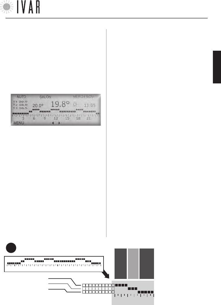
CRONOTERMOSTATO
[31]
Para ayuda ver ‘MAPA DE NAVEGACIÓN’ de la pag. 44
18 21
LÍNEA 1 – ej: 68°
LÍNEA 2 – ej: 65°
LÍNEA 3 – ej: 62°
3 6 9 12 15 18 21
DESDE LAS 18:00 H
A LAS 20:00 H
DESDE LAS 20:00 H
A LAS 21:30 H
DESDE LAS 21:30 H
A LAS 24:00 H
GRÁFICO HORARIO 7-DÍAS
(Ejemplo)
En este ejemplo la temperatura del ambiente será de
68 grados desde las 18:00 a las 20:00 horas, 65 grados
desde las 20:00 a las 21:30 horas y 62 grados desde las
21:30 a las 24:00 horas.
FIG.
4
CONFIGURACIÓN AUTOMÁTICA DE LA TEMPERATURA
Activar modo Automático (Modo Automático)
[MENÚàMODALIDAD’à
MODO AUTOMÁTICOàACTIVAR MODO AUTOMÁTICO]
Activando el modo Automático, el cronotermostato
se sujeta a un programa semanal para regular el
sistema. Se puede establecer, para cada uno de los 7
días de la semana, en cuales franjas horarias tener una
temperatura de Confort (T1), Ahorro (T2) o Límite (T3).
Acceder a la sección Modalidad y seleccionar Modo
automático usando las flechas Arriba/abajo (Ver ‘Nave-
gación del menú’ de la pág. 28). Después presionar
CONFIRMAR dos veces, activando así la opción.
Modalidad verano/invierno
[MENÚàCONFIGURACIONESàMODALIDAD VERANO/INVIERNO]
Habilita el sistema para el control de la calefacción
o refrigeración, encomendando la prioridad a la
Programación invierno o verano, respectivamente (Para
informaciones sobre la Programación invierno/verano
ver el apartado siguiente).
Acceder a Modalidad verano/invierno y utilizar las
flechas Arriba/abajo para seleccionar Verano o Invierno,
después presionar CONFIRMAR.
‘Programación invierno’ y ‘Programación verano’
[MENÚàCONFIGURACIONESàPROGRAMACIÓN INVIERNO]
[MENÚàCONFIGURACIONESàPROGRAMACIÓN VERANO]
Para definir las 3 franjas de temperatura de división
del Gráfico Horario 7-DÍAS, realizar lo que se indica a
continuación (las 3 franjas están representadas por las
líneas horizontales del gráfico: ver Figura-4 y ‘Gestión de
los set de temperatura’ de la pag. 45).
Acceder a la sección Programación invierno o a la
sección Programación verano, según la modalidad que
se quiere gestionar (ver ‘Modalidad verano/invierno’).
Utilizar las flechas Arriba/abajo para evidenciar el
campo requerido y presionar CONFIRMAR.
Utilizando las flechas Arriba/abajo, seleccionar
Configurar confort para personalizar la temperatura
T1, Configurar ahorro para T2, o Configurar límite para
T3. Regulando debidamente las temperaturas Ahorro
y Límite, el usuario puede perfeccionar la gestión del
ahorro.
Evidenciar un campo y presionar CONFIRMAR. Cada
toque de las flechas Arriba/abajo incrementa o
disminuye el valor de la temperatura de 1 °F. Al final,
presionar CONFIRMAR.
Zonas - Programación semanal
[MENÚàCONFIGURACIONESàZONAS]
Cuando la modalidad INVIERNO está activada, acceder
a la sección Zonas para personalizar el Gráfico Horario
7-DÍAS de cualquier zona de la vivienda (En esta sección
se enumeran tantas zonas como han sido definidas por
la opción ‘Numero zonas gestionadas’ - ver pag. 41.
El número inicial de zonas es 2 hasta un máximo de 8).
Seleccionar una zona con las flechas Arriba/abajo y pre-
sionar CONFIRMAR. Seleccionar con las flechas Arriba/
abajo el día de la semana
que se quiere configurar y
presionar CONFIRMAR.
Ahora utilizar los botones
Izquierda/derecha para
evidenciar la franja horaria
a modificar (48 franjas ver-
ticales dividen la jornada en
intervalos de media hora).
Después presionar Arri-
ba/abajo para asignar T1,
T2 o T3, respectivamente
300546US-10-14
ESPAÑOL
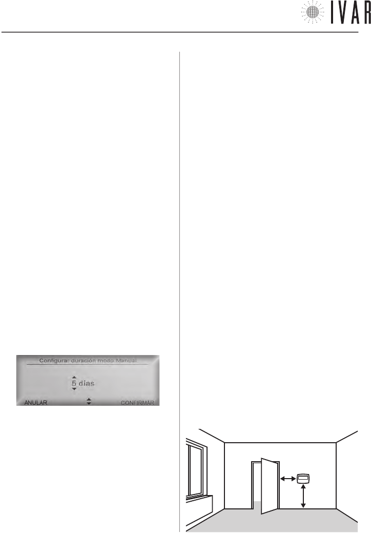
CRONOTERMOSTATO
[32]
INSTALACIÓN DEL CRONOTERMOSTATO
Seguir las siguientes instrucciones para poner en
funcionamiento el dispositivo:
1) Determinar una posición para el dispositivo e
instalarlo en la pared.
2) Colocar las pilas.
3) Asociar cada actuador al cronotermostato, definiendo
las diferentes zonas del edificio (ver el apartado
‘Asociación de un actuador con el cronotermostato‘ en
la pag. 41).
Posicionamiento típico del aparato
El cronotermostato detecta la temperatura del
ambiente y debe estar colocado en una posición donde
haya buena circulación de aire, a 5 ft del pavimento. Es
indispensable seguir las siguientes prescripciones:
• NO posicionarlo cerca de un radiador.
• NO posicionarlo cerca a puertas.
• NO posicionarlo en paredes perimetrales.
• NO posicionarlo donde está el paso de tubos en el
interior de las paredes.
• NO posicionarlo en locales que tengan condiciones de
temperatura y humedad excepcionales (Por ejemplo,
cocina y baño).
• NO posicionarlo donde el dispositivo pueda entrar en
contacto con el agua.
• NO exponerlo a la luz directa.
NOTA: cuando se posiciona el cronotermostato, se debe
verificar que los actuadores estén a una determinada
distancia. En condiciones ideales, es decir, sin ningún
obstáculo, dicho radio de cobertura es de 33 yd. Entre
los factores que pueden incidir en las prestaciones de
transmisión, considerar la humedad y las características
arquitectónicas del edificio.
5 ft
1 ft
al intervalo horario seleccionado. Para ultimar la
modificación, presionar CONFIRMAR. Es posible decidir
si aplicar a las veinticuatro horas siguientes la misma
programación. Para extenderla de un día, responder a
la pregunta del sistema, seleccionando CONFIRMAR y de
nuevo MODIFICAR. Repetir la operación hasta definir una
semana tipo.
Regulación verano - Programación semanal
[MENÚàCONFIGURACIONESàREGULACIÓN VERANO]
Cuando la modalidad VERANO está activada, acceder
a Regulación verano (*) para definir la programación
semanal. Ver el procedimiento análogo, descrito en el
apartado anterior (Zonas).
Manual para 1 hora y después Auto (Modo Manual)
[MENÚàMODALIDADàMODO MAN.àMANUAL 1 HORA...]
[MENÚàMODALIDADàMODO MAN.àMANUAL 2 HORAS...]
Acceder a la sección Modo manual y seleccionar con las
flechas Arriba/abajo la línea Man. 1 hora y después auto
para activar temporalmente esta modalidad, después
presionar CONFIRMAR. Alternativamente seleccionar
Man. 2 horas y después auto o Configurar duración
modo manual para determinar duraciones más largas.
Después, presionar CONFIRMAR. En el segundo caso
para configurar dicha duración, usar las flechas Arriba/
abajo y definir el período de tiempo necesario. Después
presionar CONFIRMAR para terminar.
Para un período superior a las 24 horas, el sistema pasa
automáticamente al recuento de los días.
NOTA: con esta modalidad, por ejemplo, se puede gestionar
el sistema en caso de un período de vacaciones. En efecto,
una regulación apropiada del programa, garantiza el restable-
cimiento anticipado de las condiciones de confort respecto a
la fecha prevista de retorno.
Apagado por 1 hora y después Auto (Modo Apagado)
[MENÚàMODALIDADàMODO APAGADOàAPAGAR POR...]
Acceder a la sección Modo apagado y ejecutar el proce-
dimiento análogo (Ver apartado anterior).
* ATENCIÓN: en la ‘Regulación verano’ no es necesario seleccionar las zonas. En Modalidad verano el sistema trabaja en ON/OFF
en todos los actuadores y en una única zona, cuya temperatura la mide directamente el cronotermostato. Se puede desactivar el
funcionamiento de verano de uno o varios actuadores (Ver Regulación de la función anticondensación de la pág. 45).
300546US-10-14
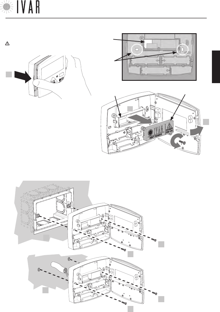
CRONOTERMOSTATO
[33]
Para ayuda ver ‘MAPA DE NAVEGACIÓN’ de la pag. 44
Instalación de pared
1) Abrir la puerta anterior del cronotermostato.
¡ATENCIÓN! Asegurarse de excluir la tensión de red
del sistema eléctrico antes de operar.
2) Después de haber desenroscado los 2 tornillos,
quitar la cobertura de la caja interna (S), como
se indica en la figura contigua. Después pasar
a través de la ranura (S1) los cables del contac-
to caldera. Efectuar la conexión eléctrica de los
cables en el borne en las posiciones ‘NO’ y ‘C’,
como se indica en el fondo de la cobertura (Ver el
‘Esquema de las conexiones’ de la pag. 35 para
mayores indicaciones). Por último, volver a colocar
la caja para cerrarla, enroscando los tornillos.
1
S1
x2
DESENROSCAR
S
2
1
S1
3
3) Posicionar el aparato de pared, ase-
gurándolo como ha sido ilustrado (3).
Las opciones son:
* A
(en caja)
3
3
* B
(de pared)
3
3
• con 2 tornillos en
correspondencia
de la caja eléctrica
503E (*A)
• con 2 tarugos de
pared (*B)
300546US-10-14
ESPAÑOL

CRONOTERMOSTATO
[34]
CARACTERISTICAS TECNICAS DEL CRONOTERMOSTATO
1) TRANSMISIÓN
• frecuencia de trabsmisión: 915.00 MHz
• capacidad de la señal: 33 yd en ausencia de obstáculos
2) ALIMENTACIÓN
• tensión: 4,5V
•
tipo de baterías: n.3 pilas alcalinas estilo AA (mod. LR6) 1,5V
• tipo de salida
- relé a contacto unipolar 5A/250Vac
- FOR US MARKET: DO NOT CONNECT VOLTAGE HIGHER
THAN 24V ac/dc TO THE OUTPUT RELAY!
• Autonomía: 3 años (con baterías nuevas en buen esta-
do y en condiciones óptimas de funcionamiento) *
• tipo de acción, desconexión y aparato:
1 / B / Electrónico digital
3) CONDICIONES AMBIENTALES
• Límites de temperatura para el transporte y el almace-
namiento: de -4 °F a +130 °F
• Límites de temperatura para el funcionamiento:
de 23 °F a +110 °F
4) CONDICIONES DE ALMACENAMIENTO DE LAS PILAS
• Temperatura: 68 °F garantizan la buena duración de
las pilas
5) CONFORMIDAD
• Normativa de referencia (LV): IEC 60730-2-9
• Normativa de referencia (EMC): FCC 15 par. 15.247
6) SEGURIDAD
• Grado de protección: IP 40
• Tipo de aislamiento: CLASE II
7) DIMENSIÓN
• Cronotermostato: L=4.95 in, H=3.90 in, W=1.00 in
8) CODIGO PRODUCTO
• Descripción: cronotermostato digital retroiluminado
con switch VERANO/INVIERNO
• EQUICALOR-AC: Art. DC 1010 Cod. 506366US
9) INTERVALOS DE TEMPERATURA
• Intervalo de muestreo: 1 minuto
• Histéresis: 0.2 °F.
* La duración de la batería puede acortarse en caso de mala
RADIO comunicación (L SIGN), en presencia de obstáculos y
en el caso de almacenamiento no conforme a las condicio-
nes establecidas. Las baterías de diferentes marcas pueden
tener comportamientos y duración más corta de lo indicado.
FCC ID: 2AB4Y506366US
Este dispositivo cumple con la parte 15 de las Normas de la FCC. El funcionamiento está sujeto a estas dos condi-
ciones: (1) este dispositivo no puede producir interferencias perjudiciales (2) este dispositivo debe tolerar cualquier
interferencia recibida, incluidas aquellas interferencias que pueden provocar un funcionamiento no deseado.
NOTE: a partir de las pruebas a las que ha sido sometido este equipo, se concluye que cumple con los límites para un
dispositivo digital de Clase B, en conformidad con la Parte 15 de las Normas de la FCC. Estos límites están destinados
a proporcionar una protección razonable contra las interferencias perjudiciales en una instalación de tipo residencial.
Este equipo genera, usa y puede emitir energía de radiofrecuencias y, si no se instala y utiliza de acuerdo con las
instrucciones, puede provocar interferencias perjudiciales en las comunicaciones vía radio. Sin embargo, no puede
garantizarse que no se produzcan interferencias en una instalación particular. Si este equipo provoca una interfe-
rencia perjudicial en la recepción de radio o televisión, que puede estar determinada por su conexión o desconexión,
el usuario ha de intentar corregir la interferencia aplicando una o varias de las siguientes medidas:
• Reorientar o reinstalar la antena receptora.
• Aumentar la distancia entre el equipo y el receptor.
• Conectar el equipo dentro o fuera de un circuito diferente al que está conectado el receptor.
• Solicitar la ayuda del vendedor o de un técnico especializado en radio/TV.
Exposición a RF: este equipo cumple con los límites de exposición a radiaciones establecidos por la FCC para un
ambiente no controlado. Este equipo debe ser instalado y operado manteniendo una distancia minima de 20 cm
entre la persona y el elemento transmisor. Este transmisor no debe estar situado o funcionando simultáneamente
con otra antena o transmisor.
Advertencia: Las modificaciones o los cambios aplicados a este dispositivo que no hayan sido aprobados expresa-
mente por IVAR podrían anular la autorización del usuario para utilizar el equipo.
300546US-10-14
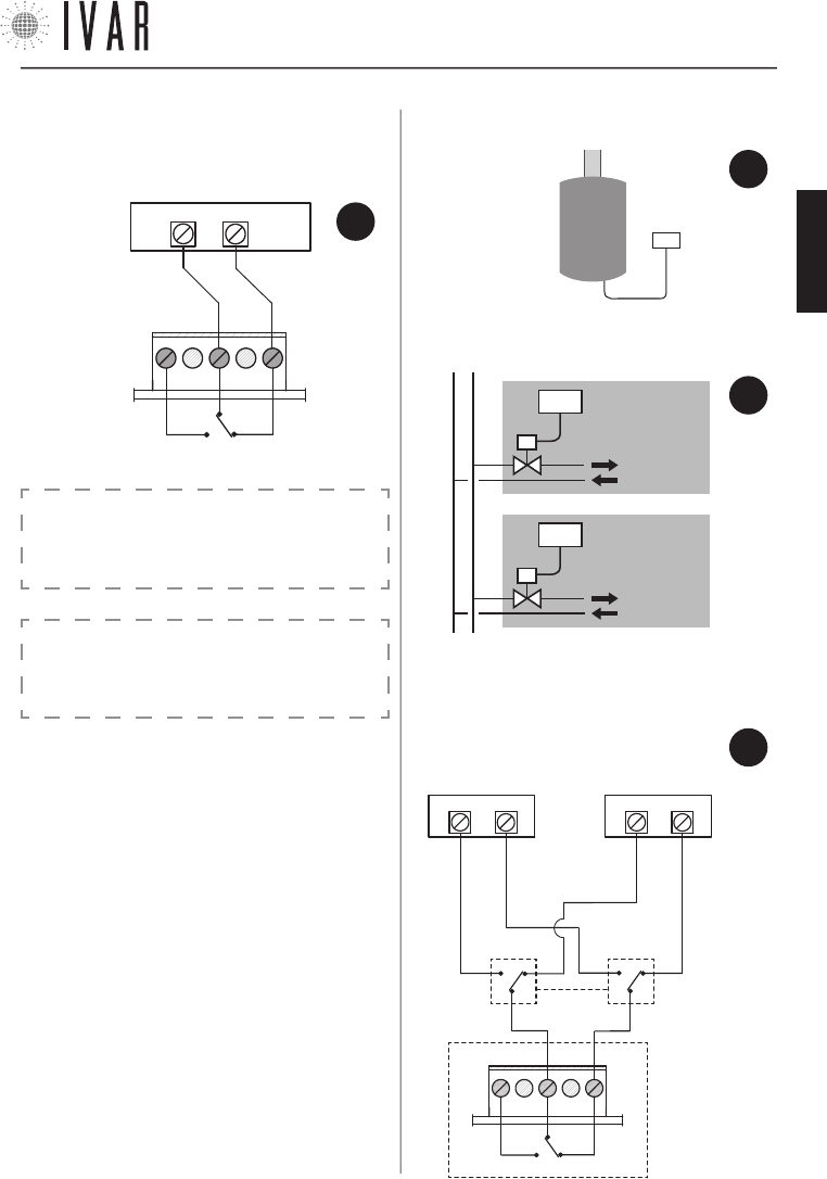
CRONOTERMOSTATO
[35]
Para ayuda ver ‘MAPA DE NAVEGACIÓN’ de la pag. 44
CRONO
UNIDAD
VIVIENDA
N° 1
UNIDAD
VIVIENDA
N° 2
CRONO
CALDERA
o VÁLVU-
LA DE
ZONA
RELÉ
NO
NC
C
FIG.
7
11) EJEMPLOS DE APLICACIÓN
• ejemplo de apli-
cación 1: caldera.
• ejemplo de aplicación 2: válvula de zona.
CRONO
10) ESQUEMA DE LAS CONEXIONES
• conexión eléctrica
• ejemplo de aplicación 3: instalaciones con dos genera-
dores para el funcionamiento VERANO/INVIERNO.
FIG.
8
FIG.
9
CRONO
0=INVIERNO
1=VERANO
0/1
C NO
NC
CALDERA o VÁLVU-
LA DE ZONA
CHILLER o VÁLVULA
DE ZONA
FIG.
10
¡ATENCIÓN! La logica de funcionamento del siste-
ma puede aplazar la activación de contacto calde-
ra de aproximadamente 15-20 minutos.
AVISO:
¡PARA EL MERCADO DE EE.UU., NO CONECTE UN VOL-
TAJE SUPERIOR A LOS 24 V ca/cc AL RELÉ DE SALIDA!
300546US-10-14
ESPAÑOL
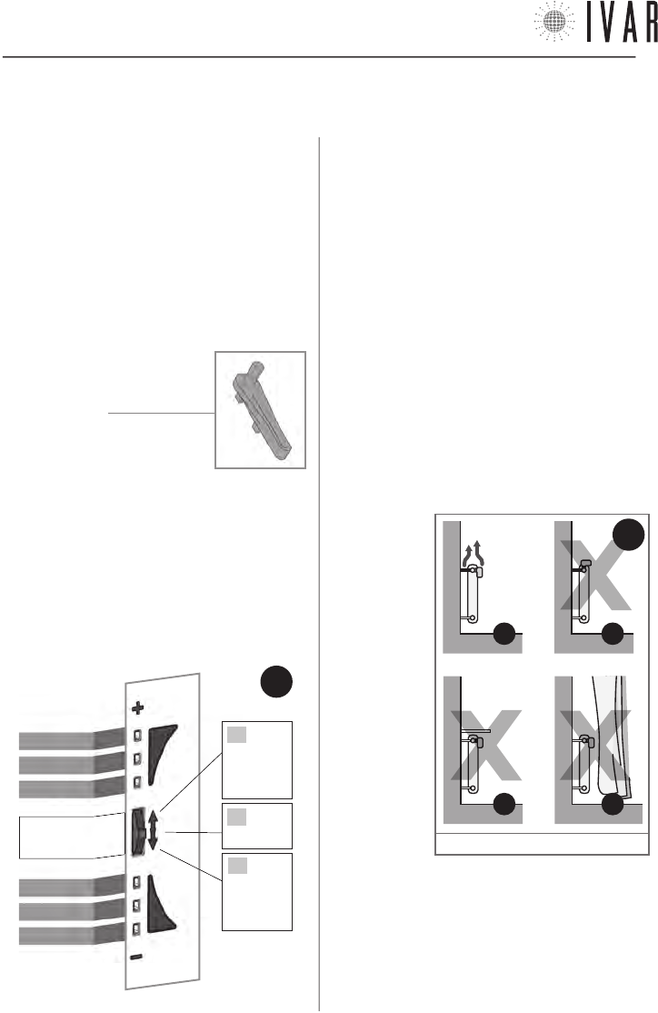
ACTUADOR
[36]
CARACTERÍSTICAS DEL ACTUADOR
Cada actuador (que se puede comprar singularmente;
suministrado por separado del cronotermostato),
ejecuta físicamente la regulación del radiador
sobre el cual está instalado, debajo de la guía del
cronotermostato.
Si además se quiere mejorar el confort local de un
ambiente particular o parte del mismo, se puede dirigir
inmediatamente cada uno de los actuadores. De este
modo, se obtiene el rendimiento máximo con precisión
y simplicidad.
CONTENIDO DE LA CAJA
• Actuador
• Llave de utilidad
• Pilas alcalinas stilo
• Folleto de instrucciones
INDICADOR LED Y SELECTOR FRONTAL
Los mandos del actuador se encuentran en el lado
frontal del dispositivo. Están compuestos por:
• Indicador de led [LED de 1 a 6]
• Selector frontal [tecla de mando]
La tecla selector frontal opera en tres posiciones:
A) Posición ‘+’ (ALTO)
B) Posición ‘SELECCIONAR’ (Presión de la tecla)
C) Posición ‘-‘ (BAJO)
LED 1
LED 2
LED 3
LED 4
LED 5
LED 6
SELECTOR
FRONTAL
B
PRESIONAR
A
EMPUJAR
HACIA
ARRIBA
C
EMPUJAR
HACIA
ABAJO
2. ACTUADOR
ADVERTENCIAS
1. En el montaje del actuador se aconseja proteger el
zuncho dentado con un trapo cuando se lo aprieta.
2. Cuando se opera con el actuador, tener cuidado de
no ponerlo en contacto con el agua y exponerlo a tasas
elevadas de humedad.
3. El procedimiento de configuración de las opciones del
actuador debe ser encomendado al instalador.
4. Es importante verificar la plena eficiencia de las pilas
para prevenir la parada del sistema de calefacción/
refrigeración debidos a la ausencia de alimentación del
actuador. En condiciones normales de funcionamiento
del dispositivo y de buena conservación de las pilas
durante el tiempo de almacenamiento, la duración de las
pilas es de 3 años.
5. Sujetarse a las siguientes indicaciones para el
empleo de las pilas: cuando fuera necesario eliminarlas,
tirarlas separadamente en el contenedor de recogida
diferenciada; sujetarse a las instrucciones de instalación
proporcionadas; evitar conectar los polos metálicos que
se encuentran
en contacto con
las pilas para
no causar un
cortocircuito;
usar siempre
el tipo de pilas
especificado
en el manual;
no mezcle pilas
diferentes,
viejas con
nuevas o pilas
alcalinas con
pilas estándar
de cinc-carbón;
el empleo de
pilas recargables
implica una
menor autonomía de funcionamiento respecto a las pilas
no recargables.
6. Si el dispositivo provocara interferencias con otros
aparatos eléctricos, alejarlos inmediatamente.
7. Al final del ciclo de vida del aparato, no dispersarlo en el
ambiente. Eliminarlo respetando las leyes vigentes.
8. Seguir las indicaciones de la Figura 12 para el
posicionamiento del actuador.
MANDOS DEL
ACTUADOR
FIG.
11
11
B*
11
A
11
D*
11
C*
FIG.
12
* Ver ‘Sensor remoto’ de la pag. 38
300546US-10-14
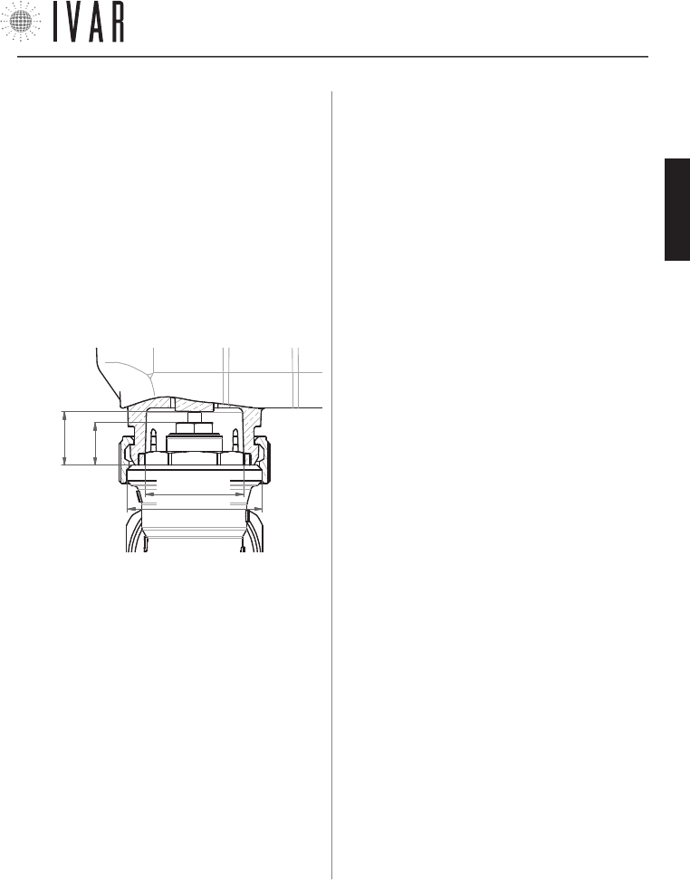
ACTUADOR
[37]
Para ayuda ver ‘MAPA DE NAVEGACIÓN’ de la pag. 44
DISTANCIA DE CIERRE
(X)
MAX=
0.37 in
MAX Ø0.83 in
M30x1,5
4) CONDICIONES AMBIENTALES
• Límites de temperatura para el transporte y el almace-
namiento: de -4 °F a +130 °F
• Límites de temperatura para el funcionamiento:
de 23 °F a +110 °F
5) CONDICIONES DE ALMACENAMIENTO DE LAS PILAS
• Temperatura: 68 °F garantizan la buena duración de
las pilas
6) CONFORMIDAD
• Normativa de referencia (EMC): FCC 15 par. 15.247
7) SEGURIDAD
• Tipo de aislamiento: CLASE III
8) DIMENSIÓN
• L=3.60 in, H=1.90 in, W=2.60 in
9) CODIGO PRODUCTO
• Descripción: servomotor axial
• EQUICALOR-A: Art. AS 1000 Cod. 506364US
CARACTERÍSTICAS TÉCNICAS DEL ACTUADOR
1) TRANSMISIÓN
• frecuencia de transmisión: 915.00 MHz
• Capacidad de la señal: 33 yd en ausencia de obstáculos
2) ALIMENTACIÓN
• Tensión: 4,5 V
•
Tipo de baterías: 3 pilas alcalinas estilo AA (mod. LR6) 1.5V
• Autonomía: 3 años (con baterías nuevas en buen esta-
do y en condiciones óptimas de funcionamiento) *
• Tipo de aparato: Electrónico digital
3) ACOPLAMIENTO
• Tipo de acoplamiento: M30x1,5
•
Distancia de cierre ( X ): comprendida entre 0.41 y 0.47 in
FCC ID: 2AB4Y506364US
Este dispositivo cumple con la parte 15 de las Normas
de la FCC. El funcionamiento está sujeto a estas dos
condiciones: (1) este dispositivo no puede producir in-
terferencias perjudiciales (2) este dispositivo debe to-
lerar cualquier interferencia recibida, incluidas aquellas
interferencias que pueden provocar un funcionamiento
no deseado.
NOTE: a partir de las pruebas a las que ha sido someti-
do este equipo, se concluye que cumple con los límites
para un dispositivo digital de Clase B, en conformidad
con la Parte 15 de las Normas de la FCC. Estos límites
están destinados a proporcionar una protección razona-
ble contra las interferencias perjudiciales en una insta-
lación de tipo residencial. Este equipo genera, usa y pue-
de emitir energía de radiofrecuencias y, si no se instala y
utiliza de acuerdo con las instrucciones, puede provocar
interferencias perjudiciales en las comunicaciones vía
radio. Sin embargo, no puede garantizarse que no se
produzcan interferencias en una instalación particular.
Si este equipo provoca una interferencia perjudicial en la
recepción de radio o televisión, que puede estar deter-
minada por su conexión o desconexión, el usuario ha de
intentar corregir la interferencia aplicando una o varias
de las siguientes medidas:
• Reorientar o reinstalar la antena receptora.
• Aumentar la distancia entre el equipo y el receptor.
• Conectar el equipo dentro o fuera de un circuito dife-
rente al que está conectado el receptor.
• Solicitar la ayuda del vendedor o de un técnico espe-
cializado en radio/TV.
Exposición a RF: este equipo cumple con los límites de
exposición a radiaciones establecidos por la FCC para
un ambiente no controlado. Este equipo debe ser in-
stalado y operado manteniendo una distancia minima
de 20 cm entre la persona y el elemento transmisor.
Este transmisor no debe estar situado o funcionando
simultáneamente con otra antena o transmisor.
Advertencia: Las modificaciones o los cambios aplica-
dos a este dispositivo que no hayan sido aprobados ex-
presamente por IVAR podrían anular la autorización del
usuario para utilizar el equipo.
*
La duración de la batería puede acortarse en caso de mala RADIO comunicación (L SIGN), en presencia de obstáculos y en el caso de
almacenamiento no conforme a las condiciones establecidas. Las baterías de diferentes marcas pueden tener comportamientos y
duración más corta de lo indicado.
300546US-10-14
ESPAÑOL
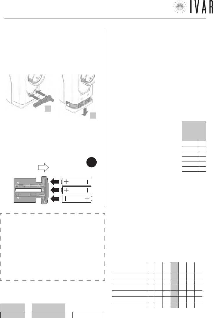
ACTUADOR
[38]
REGULACIÓN DE LA TEMPERATURA DE CONFORT LOCAL
Respecto a la Temperatura configurada para una sola
zona en el modo de funcionamiento manual o au-
tomático del cronotermostato, se puede realizar una
corrección inmediata a un determinado radiador a
través del botón selector frontal del relativo actuador.
Por ejemplo, si dos cámaras han sido asignadas a una
cierta zona, se ofrece la posibilidad de aumentar o di-
sminuir hasta unos 6 °F la temperatura presente en una
de éstas dos; o también obtener la mejor temperatura
para la habitación que se está ocupando sin tener que
modificar la programación del sistema (Ver Tabla-1a).
El procedimiento que se describe a continuación se
refiere exclusivamente a los actuadores asociados
a zonas diferentes de la Zona1.
Para acceder a la modificación de la
Temperatura confort local, mantener
el selector frontal en posición
SELECCIONAR, hasta que se iluminen
los LED 3 y 4, que se produce después
de 5 segundos (Ver Tabla contigua).
Soltar el selector después de dicha
indicación. El indicador led ilustra la
Corrección local actual (Ver Tabla-1b).
Ahora para alzar o bajar la temperatura de aprox. 2 °F,
tocar el selector en posición ‘+’ o ‘-’. Cada toque varía
la temperatura dentro del intervalo total comprendido
entre aprox. +6 °F a unos -6 °F. Si, por ejemplo, una
zona está regulada según un valor de 62 ºF, el confort
local de cada actuador puede ir de aprox. 56 °F a 68 °F.
Después de haber configurado la temperatura deseada
(ver Tabla-1b), una espera de 5 segundos concluye el
procedimiento según la nueva configuración.
Señal:
µ = Led
encendido
Led 1 µ
Led 2 µ
Led 3 µ
Led 4 µ
Led 5 µ
Led 6 µ
ABRIR
FIG.
13
INSTALACIÓN/SUSTITUCIÓN DE LAS PILAS
El actuador usa n. 3 pilas alcalinas AA 1,5V. Se deben
colocar las pilas para que el aparato funcione.
1) Para sustituir las pilas usar la llave de utilidad, que se
suministra en la caja.
2) Desbloquear la ranura de las pilas, introduciendo la
llave de utilidad como se indica en la figura.
3) Quitar la ranura de alojamiento de las pilas y colocar
las pilas según el orden y el sentido indicado en el fondo
de la ranura (Ver Figura-13).
4) Reposicionar la ranura, desplazándola completamente
hasta que se dispare el bloqueo.
SENSOR REMOTO
(OPCIONAL)
Se puede conectar un sensor remoto de temperatura
ambiental (suministrado como opcional - Art. AE 1000) a
los actuadores, determinando la exclusión de su sensor
integrado. La sonda remota permite detectar la tempe-
ratura en un punto preestablecido si el actuador ha sido
instalado en una posición desfavorable.
ATENCIÓN: no se puede aplicar el sensor remoto a los
actuadores de Zona1’.
TABLA 1a
TEMPERATURA CONFORT LOCAL ( Ejemplo)
T. CONFIGURADA CORRECCIÓN LOCAL T. CONFORT LOCAL
64 °F + aprox. 4 °C = aprox. 68 °F
2
3
TABLA 1b: DEFINICIÓN DE LA CORRECCIÓN LOCAL
corrección de la
temperatura à
-3 -2 -1 +0 +1 +2 +3
Led 1 µµµ µµµ
Led 2 µµµ µµµ
Led 3 µµµµµµ µ
Led 4 µµµµµµµ
Led 5 µµµ µ µ µ
Led 6 µµµ µµµ
NB µ = Led encendido
300546US-10-14
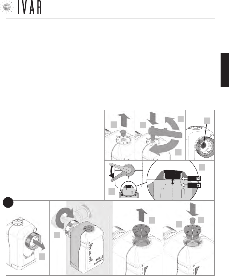
ACTUADOR
[39]
Para ayuda ver ‘MAPA DE NAVEGACIÓN’ de la pag. 44
DESBLOQUEO MANUAL
En caso de necesidad, maniobrar manualmente como
se indica a continuación para realizar la regulación de
emergencia.
• Extraer el perno del disco numerado superior (2).
• Presionar en el alojamiento la llave de utilidad (3).
• Desbloquear el actuador girando lentamente la llave
de utilidad hasta la posición requerida (4a/4b), como
superior del actuador (Ver figura).
9) Reposicionar el disco numerado, verificando que el ‘0’ esté
alineado con la muesca de referencia (*); después presionar
el disco en su alojamiento.
10) Reposicionar el perno de fijación.
11) Para terminar la fase de cierre/apertura asistida, es in-
dispensable mantener el selector en posición SELECCIONAR
hasta que se iluminen los Led 3 y 4, que se produce después
de 5 segundos. Después de dicha señal, soltar la tecla.
12) Realizar la asociación del actuador y la verificación final.
(Ver ‘Asociación de un actuador con el cronotermostato’ en el
capítulo ‘SECCIÓN TÉCNICA’).
INSTALACIÓN DEL ACTUADOR
1) Asegurarse de haber colocado las pilas (ver
pag. 38)
2) Quitar (con un pequeño destornillador) el perno
de fijación del disco superior numerado como se
indica en la figura.
3) Presionar en el alojamiento la llave de utilidad.
4) Poner el actuador en apertura total, girando
lentamente la llave en sentido antihorario hasta
llegar a unos 45° del final de carrera (4a), para
alinear el pistón (4c) con el punto de mínimo. Di-
cho punto está indicado en la figura en el detalle
4d. Después quitar la llave.
5) Alzar el zuncho roscado de conexión en el sen-
tido indicado.
6) Asegurar el actuador al radiador enroscando
manualmente el zuncho roscado, apretándolo
con una llave adecuada.
7) Poner el actuador en cierre total, mantenien-
do el selector frontal del actuador en posición ‘-‘
hasta el primer parpadeo del Led 4 (Ver Figura-11
de la pag. 36), que se produce después de 5
segundos. Soltar la tecla después de dicha señal.
La intermitencia rápida contemporánea de los
Led 4, 5 y 6 indica que se ha realizado el cierre.
8) Quitar el disco numerado que está en la parte
se ilustra en la figura. Las cifras para la regulación son: ‘0‘
para el cierre máximo y ‘6‘ para la apertura máxima. Si la
escala numérica no estuviera posicionada correctamente,
llevar el actuador en posición de cierre total (girando la
llave en sentido horario hasta el final de la carrera) y po-
steriormente realizar lo indicado en los puntos 8 y 9 de las
operaciones de Instalación del actuador (Ver pag. 39).
• Extraer la llave y colocar el perno de fijación.
6*
910
5
8
FIG.
14
4c
3
4a
4b
2
4d
4c
MIN
MAX
300546US-10-14
ESPAÑOL
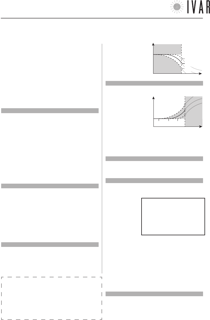
SECCIÓN TÉCNICA
[40]
Lista a título de ejemplo de las alarmas:
---Fecha------Hora-----ID----ERR---
10/02/11 07.00.00 CR00 L BATT
03/02/08 11.10.21 AC02 ERR MO
19/01/12 09.05.30 AC03 L SIGN
12/01/10 05.22.59 AC05 ERR TE
NOTAS GENERALES DE FUNCIONAMIENTO
La detección de la temperatura ambiente se produce
directamente en el cronotermostato para la Zona 1 (Ma-
ster) y en los actuadores de las zonas 2-8 (Slave). Un algo-
ritmo patentado permite corregir el efecto de proximidad
que se origina en las zonas 2-8 por la cercanía existente
entre el detector y la fuente de calor.
3. SECCIÓN TÉCNICA
3.1
CRONOTERMOSTATO – SETUP
Acceder a la sección Configuraciones avanzadas (Ver ‘Navega-
ción del menú’ en la pag. 28 para informaciones sobre las te-
clas de mando) para ajustar las opciones del sistema según las
características específicas del edificio (MENÚàCONFIGURACIO-
NESàCONFIGURACIONES AVANZADAS... esta ruta se indicará en
el capítulo presente con un asterisco por brevedad).
Durante la fase de encendido, responder a la pregunta del si-
stema, seleccionando CONFIRMAR para continuar. A continua-
ción se enumeran las ‘Configuraciones avanzadas’.
Límites
[ *àINSTALACIÓNàLIMITESàINVIERNO]
[ *àINSTALACIÓNàLIMITESàVERANO]
Para determinar el valor máximo y mínimo de cada uno de los
6 campos de temperatura que componen la Programación in-
vierno y la Programación verano, acceder a la sección Límites
(Para mayor información sobre las PROGRAMACIÓNES ver Ge-
stión de las configuraciones de temperatura en la pág. 45).
Usar las flechas Arriba/abajo para seleccionar una regulación
Verano o Invierno, presionar CONFIRMAR. Seleccionar un valor
a modificar dentro del grupo de regulación escogido (Verano o
Invierno) y presionar CONFIRMAR. Con las flechas Arriba/aba-
jo regular el valor (máximo y mínimo) relativo a Confort-T1,
Ahorro-T2 o Límite-T3. Después, presionar CONFIRMAR.
Preactivaciones (Anticipo máximo arranque y apagado)
[*àINSTALACIÓNàPREACTIVACIONESàANTICIPO MÁXIMO AR-
RANQUE]
[*àINSTALACIÓNàPREACTIVACIONESàANTICIPO MÁXIMO APA-
GADO]
Define el límite máximo del tiempo que se calcula en au-
tomático por el cronotermostato para el encendido/apagado
optimizados del sistema (OPTIMIZACIÓN ENCENDIDO/OPTIMI-
ZACIÓN APAGADO). El tiempo está expresado en minutos y se
puede modificar con un paso de 1 minuto. Usar las flechas
Arriba/abajo para regular, presionar CONFIRMAR.
Preactivaciones (Pre-start ahorro reducido)
[*àINSTALACIÓNàPREACTIVACIONESàPRE-START AHORRO
REDUCIDO]
Regular este valor para definir la entidad de la caída de tem-
peratura que se obtiene a la salida de la franja confort, cuando
está activa la OPTIMIZACIÓN APAGADO. Este valor está confi-
gurado por defecto en
1 °F. Usar las flechas
Arriba/abajo para re-
gular, presionar CON-
FIRMAR.
Preactivaciones (Índice prestart confort)
[*àINSTALACIÓNàPREACTIVACIONESàÍNDICE PRESTART CON-
FORT]
Regular este valor
para definir la anti-
cipación de la franja
confort que el sistema
aplica a la función de
OPTIMIZACIÓN ENCEN-
DIDO. El índice está
configurado por defecto en 30 (10 = mínimo, 60 = máximo).
Un valor inferior minimiza el prestart, mientras un valor supe-
rior lo acentúa. Usar las flechas Arriba/abajo para modificar,
presionar CONFIRMAR.
Diagnóstico (Desviación TPR memorizada)
[*àINSTALACIÓNàDIAGNOSTICOàDESVIACIÓN TPR MEMORIZ.]
Acceder para visualizar el parámetro Desviación TPR, que inter-
viene en la regulación de las zonas. Presionar SALIR para volver.
Diagnóstico (Historial alarmas)
[*àINSTALACIÓNàDIAGNOSTICOàHISTORIAL ALARMAS]
Acceder para visualizar la lista cronológica de los avisos (pre-
sentes y pasados)
propuestos por el
sistema. Presionar
SALIR para volver.
En la lista se indica
la fecha y la hora
de detección del
problema y después
el ID (identificador) del dispositivo afectado y el tipo de pro-
blema (ERR). El ID especifica el tipo de aparato sujeto al aviso
(CR=cronotermostato, AC=actuador) y también su número de
identificación. Las posibles alarmas (ERR) pueden referirse:
1) L BATT = Pilas descargadas
2) L SIGN = Baja capacidad de comunicación radio
3) ERR TE = Fallo del sensor de temperatura (integrado/remoto)
4) ERR MO = Fallo del motor eléctrico
NOTA: los errores 1, 2 y 3 se indican también en los actuadores
(Ver ‘Señales‘ de la pag. 42).
Diagnóstico (Reset alarmas)
[*àINSTALACIÓNàDIAGNOSTICOàRESET ALARMAS]
Para cancelar la cronología de las alarmas, seleccionar ON, uti-
lizando la flecha Arriba. Después presionar CONFIRMAR para
ejecutar la modificación.
Temperatura
T1
Tiempo
0.5
1.0
1.5
T2
Temperatura
T1
Tiempo
60 30 10
T2
300546US-10-14
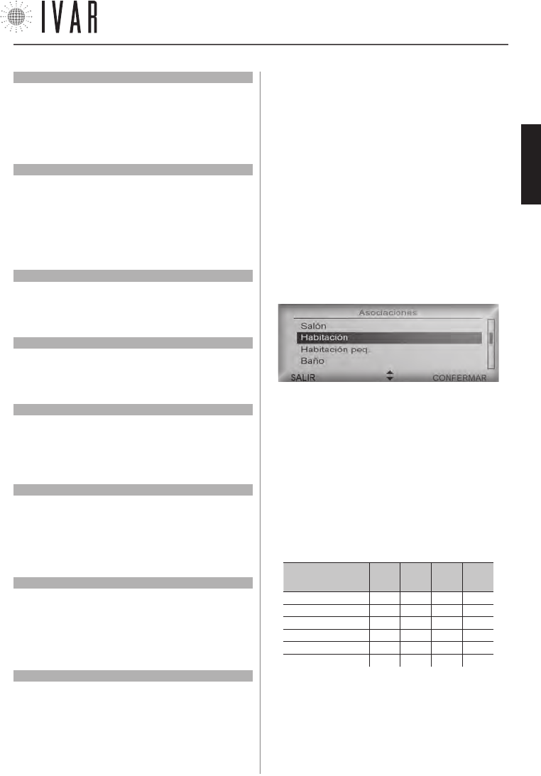
SECCIÓN TÉCNICA
[41]
Para ayuda ver ‘MAPA DE NAVEGACIÓN’ de la pag. 44
Diagnóstico (Activar modalidad diagnóstico)
[*àINSTALACIÓNàDIAGNOSTICOàACTIVAR MODALIDAD DIA-
GNÓSTICO]
Per reposicionar el cronotermostato en modo Test, seleccio-
nar ON, utilizando la flecha Arriba. Después presionar CON-
FIRMAR para ejecutar la modificación. Activar esta función,
aumenta el consumo de las pilas.
Diagnóstico (Identificación actuador)
[*àINSTALACIÓNàDIAGNOSTICOàIDENTIFICACIÓN ACTUADOR]
Para identificar un actuador particular, seleccionar un núme-
ro de identificación usando las flechas Arriba/abajo. Después
presionar CONFIRMAR para iniciar la fase de identificación.
Dicha operación puede durar un minuto. Inmediatamente de-
spués de haber sido individuado, el actuador correspondiente
al número seleccionado se activará el destello del Indicador led.
Diagnóstico (Identificación zona)
[*àINSTALACIÓNàDIAGNOSTICOàIDENTIFICACIÓN ZONA]
Procedimiento análogo a la identificación de una actuador,
involucra todos los dispositivos pertenecientes a la zona se-
leccionada (ver ‘Identificar actuador’).
Nombre usuario
[*àINSTALACIÓNàNOMBRE USUARIO]
Para identificar el dispositivo servido por el cronotermostato y
las relativas zonas asociadas, asignar un nombre a este cam-
po. Ver ‘Nombres zonas’ de la pag. 30 para indicaciones.
Configuración área
[*àINSTALACIÓNàCONFIGURACIÓN ÁREA]
Si las condiciones de transmisión con los actuadores son
desfavorables, se puede intervenir en la capacidad de la señal
de radio. Para ello, acceder a la sección Configuraciones área y
seleccionar Área normal con las flechas Arriba/abajo.
Numero zonas gestionadas
[*àINSTALACIÓNàNUMERO ZONAS GESTIONADAS]
Después de haber dado otra confirmación, es posible modifi-
car el número total de las zonas asociables, que pueden llegar
a un máximo de 8.
NOTA: las zonas excluidas pueden restablecerse en un segun-
do momento.
Reset parámetros avanzados
[*àINSTALACIONàRESET PÁRAMETROS AVANZADOS]
Activar esta función cuando se quieran cancelar las modifica-
ciones aportadas a las configuraciones avanzadas. Se presen-
ta con un aviso antes de poder continuar.
Seleccionar ON, utilizando la flecha Arriba. Después presionar
CONFIRMAR para ejecutar el mando.
Reset total cronotermostato
[*àINSTALACIÓNàRESET TOTAL CRONOTERMOSTATO]
Por medio de esta opción se puede reconducir totalmente el
cronotermostato al estado inicial, según las configuraciones
de fábrica.
Después de haber dado otra confirmación, restablecer las
franjas horarias y todos los parámetros. Seleccionar ON, uti-
lizando la flecha Arriba. Después presionar CONFIRMAR para
ejecutar el mando. Se cancelarán los datos relativos a los ac-
tuadores asociados y todas las opciones modificadas después
de la instalación. Para poder reutilizar los actuadores, ejecutar
las operaciones de asociación como se indica en el capítulo
siguiente.
ASOCIACIÓN DE UN ACTUADOR CON EL CRONOTERMOSTATO
Cada actuador requiere un procedimiento base para estable-
cer una conexión con el cronotermostato que se define como
‘Asociación’. Cuando el actuador no está asociado, responde a
cada toque del selector frontal con la Señal A* (Ver ‘Señales’ en
el capítulo siguiente).
Para iniciar la transmisión al cronotermostato, operar en los
mandos del crono del modo siguiente. Para iniciar, presionar
la tecla MENÚ y seleccionar Asociaciones usando las flechas
Arriba/abajo. Después, presionar CONFIRMAR.
Seleccionar la zona deseada de la lista en el menú, usando las
flechas Arriba/abajo y después CONFIRMAR (para personalizar
los nombres de las zonas, ver ‘Nombres zonas’ de la pag. 30).
Ahora se puede realizar la asociación de un actuador a la
zona que se ha escogido. Activar la función de búsqueda,
manteniendo el selector en posición SELECCIONAR hasta que
se iluminen los Led 2 y 5, que se produce después de 10
segundos. Soltar la tecla después de dicha señal. La búsqueda
permanece activa por 5 minutos.
ILUMINACIÓN DEL INDICADOR LED TRAS
LA PERSIÓN DEL SELECTOR FRONTAL
Duración de la
presión à
5
seg.
10
seg.
20
seg.
30
seg.
Led 1 µµµµ
Led 2 µµµ µ
Led 3 µµµµ
Led 4 µµµµ
Led 5 µµµ µ
Led 6 µµµµ
(µ = Led encendido)
La Señal C* del actuador define el éxito de la operación (Ver
‘Señales’ en la pag. 42). Ahora realizar la verificación; ver el
apartado siguiente.
Verificación de la asociación correcta
Al final del procedimiento de asociación, ejecutar en el crono-
300546US-10-14
ESPAÑOL
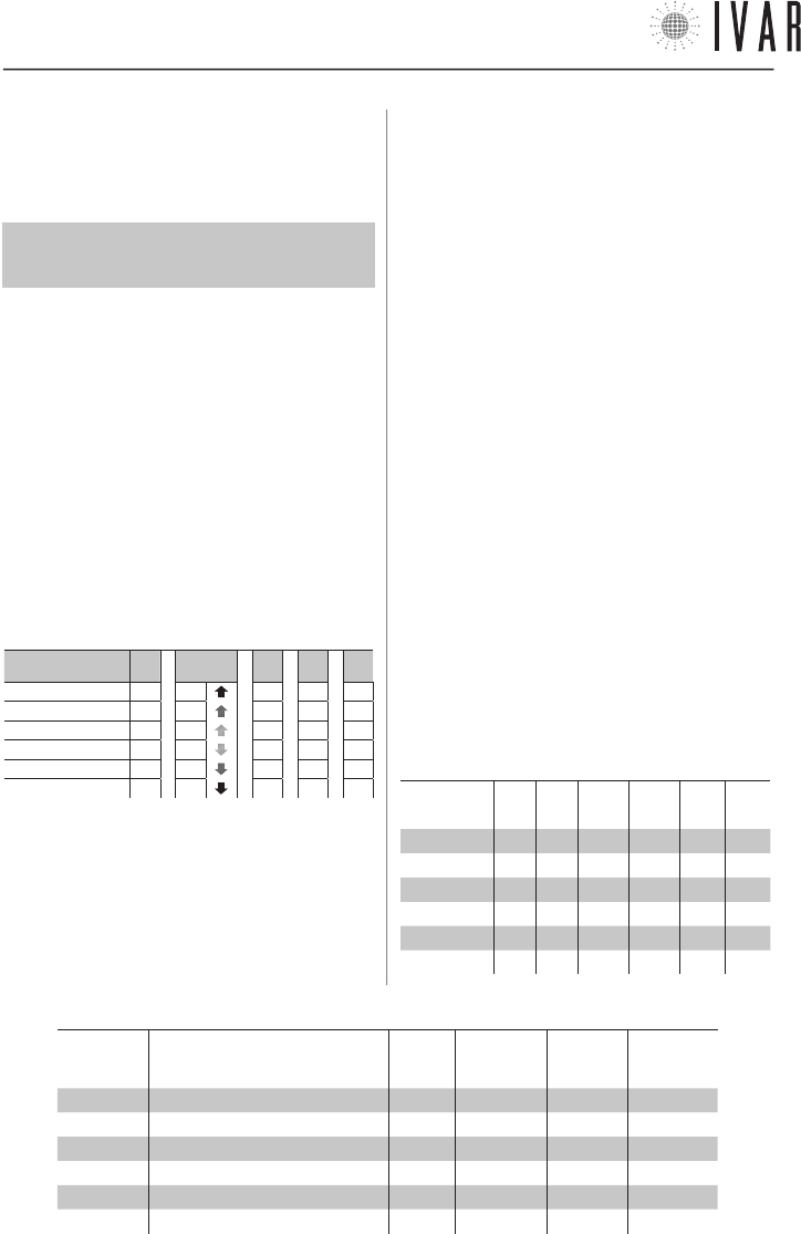
SECCIÓN TÉCNICA
[42]
termostato la función diagnóstica de identificación del ac-
tuador. Ver Diagnóstico (Identificación del actuador) en la
pag. 41.
Gestión de los actuadores
Para un funcionamiento correcto del sistema, es
INDISPENSABLE definir como Zona1 el local donde está
alojado el cronotermostato.
El sistema puede gestionar hasta un máximo de 28 actua-
dores, que se pueden distribuir en 8 zonas.
Si se debiera sustituir uno de los actuadores, asociar uno
nuevo siguiendo el procedimiento descrito hasta un máxi-
mo de 4 sustituciones. Si se alcanza dicho número de nue-
vos dispositivos, ejecutar el procedimiento siguiente antes
de asociar nuevos actuadores:
1) Ejecutar el ‘Reset total del cronotermostato‘.
2) Asociar todos los actuadores (hasta un máx. de 28).
3.2
ACTUADOR – SETUP
Señales
A continuación se enumeran los tipos de señales que el In-
dicador led puede aplicar:
INDICADOR LED: SEÑALES INTERMITENTES
Tipo de señal àA* B* C* T1* T2*
Led 1 µµµµµ
Led 2 µµµµµ
Led 3 µµµµµ
Led 4 µµµµµ
Led 5 µµµµµ
Led 6 µµ µ µµ
• A* ACTIVO - rápida intermitencia contemporánea de los
led centrales (LED 3 y 4), repetida 3 veces.
• B* BÚSQUEDA - tránsito rápido del parpadeo del centro
(LED 3 y 4) en los extremos (LED 1 y 6), repetido 3 veces.
• C* CONFIRMAR - parpadeo de 1 segundo de todos los led,
repetido 3 veces.
• T1* TEST APERTURA - rápida intermitencia contem-
poránea de los led 1, 2 y 3, (repetida 3 veces).
• T2* TEST CIERRE - rápida intermitencia contemporánea
de los led 4, 5 y 6, (repetida 3 veces).
• ANOMALÍA - en caso de alarmas activas el indicador co-
munica con cada toque del selector frontal los siguien-
tes avisos: L BATT (Led 3 y 4 encendidos) - L SIGN (Led
2 y 5 encendidos) - ERR TE (Led 1 y 6 encendidos). Ver
‘Diagnóstico (Historial de alarmas)’ de la pág. 40.
Setup de las opciones (selección y modificación)
1) SELECCIÓN DE UN PARÁMETRO (ver Tabla-2)
Para iniciar la configuración de los parámetros, mantener
el selector en posición SELECCIONAR hasta que se iluminen
los Led 1 y 6, que se produce después de 20 segundos.
Soltar la tecla después de dicha señal. Ajustar el selector
en el sentido ‘+’ o ‘-’ para navegar a lo largo de los pará-
metros de 1 a 6, indicados por los led parpadeantes. Para
configurar el parámetro seleccionado, mantener el se-
lectoren posición SELECCIONAR hasta que se iluminen los
Led 3 y 4, que se produce después de 5 segundos. Soltar
la tecla después de dicha señal (un período de 60 segun-
dos de inactividad o la presión en posición SELECCIONAR
por un tiempo de 20 segundos, concluye la programación).
2) MODIFICACIÓN DE UN PARÁMETRO (ver Tabla-3)
Ajustar el selector frontal en el sentido ‘+’ o ‘-’ para modifi-
car el valor del parámetro precedentemente seleccionado,
indicado por el led de luz fija. Después mantener en posi-
ción SELECCIONAR durante 5 segundos para confirmar el
TABLA 2: SELECCIÓN DE LOS PARÁMETROS
Led parpa-
deante Parámetro Sigla Predeter-
minado Mínimo Máximo
LED 1 (1) Servicio Srv C - -
LED 2 (2) Función anticondensación Acd C - -
LED 3 (3) Histéresis [°F] Ist 0.2 0.2 1.2
LED 4 (4) Apertura máxima Pmax 8 6 13
LED 5 (5) Correctivo de posición Cp 3 2 7
LED 6 (6) Coeficiente proporcional Kp 0,10 0,01 0,20
TABLA 3: MODIFICACIÓN DE LOS PARÁMETROS
Parámetro à(1)
Srv
(2)
Acd
(3)
Ist [°F]
(4)
Pmax
(5)
Cp
(6)
Kp
LED 1 - - 1.2 13 7 0,20
LED 2 - - 1.0 11 6 0,15
LED 3 - - 0.8 9 5 0,10
LED 4 A - 0.6 8 4 0,06
LED 5 B B 0.4 7 3 0,03
LED 6 C C 0.2 6 2 0,01
300546US-10-14
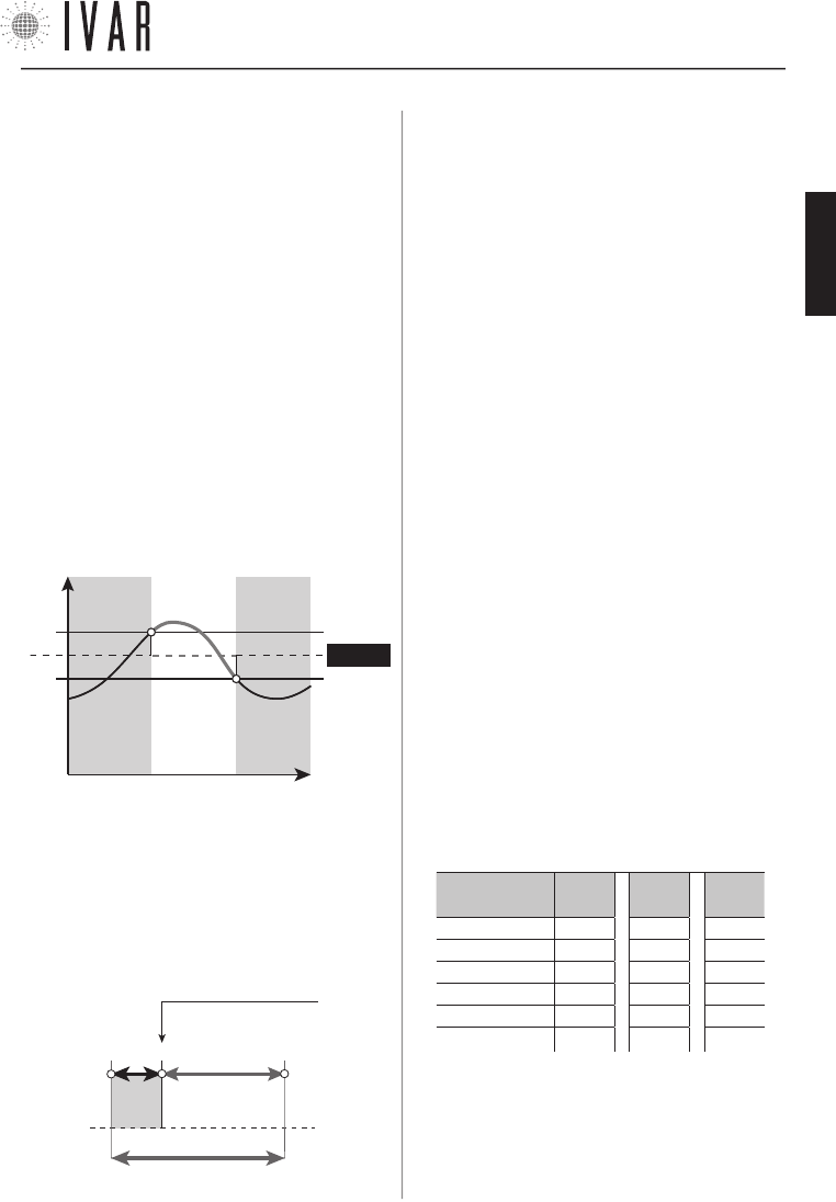
SECCIÓN TÉCNICA
[43]
Para ayuda ver ‘MAPA DE NAVEGACIÓN’ de la pag. 44
valor seleccionado. El parpadeo del LED 3 y 4 indica el éxito
del procedimiento y el retorno a la lista de los parámetros.
Después soltar la tecla. Un período de 60 segundos de inac-
tividad concluye la programación sin aportar la modifica-
ción del parámetro que se está configurando.
NOTA: se puede realizar la configuración de las opciones,
también si el actuador no ha sido asociado aún a un cro-
notermostato.
PARÁMETROS
1) Servicio
• A = Desasociación del cronotermostato
• B = Reset del actuador
• C = Ninguna acción (Predeterminada)
2) Anticondensación
(Ver ‘Función anticondensación’ de la pag. 45)
3) Histéresis
Dicho parámetro está activo sólo en funcionamiento ON/OFF
y representa la desviación positiva/negativa del setpoint,
útil para determinar el cierre/apertura de la válvula.
- Ist.
SETPOINT
ABIERTA CERRADA ABIERTA
Temperatura
Tiempo
+ Ist.
4) Pmax
Define la franja de trabajo proporcional del actuador.
5) Cp (Correctivo de posición del actuador)
Representa el punto teórico de cierre de la válvula (ver el
gráfico). Visto que el actuador se pone realmente en so-
brerrecorrido a causa de la elasticidad de la goma de her-
meticidad, durante la reapertura el Cp permite corregir
inmediatamente dicho posicionamiento.
Cp + Pmax
0* 3 12
Punto de cierre teórico
de la válvula
Pmax=9
Cp=3
Sobrerrecorrido
* La posición ‘0’ de cierre se encuentra en modo auto-adapta-
ción del actuador.
6) Kp (Coeficiente de proporcionalidad)
El desplazamiento del actuador es proporcional a la dife-
rencia entre la temperatura requerida y aquella efectiva.
Aumentando Kp se producen desplazamientos más pe-
queños, reduciendo Kp se obtienen desplazamientos más
grandes. Kp=0,01 (valor mínimo) implica funcionamiento
ON/OFF.
Operación automática de apertura/cierre
A) Poner el actuador en apertura total, manteniendo el se-
lector frontal del actuador en posición ‘+‘ hasta el primer
parpadeo del Led 3 , que se produce después de 5 segun-
dos. Soltar la tecla después de dicha señal. La Señal T1*
indica la apertura (Ver ‘Señales’ de la pag. 42). Después
presionar el selector en posición SELECCIONAR hasta la
Señal A*, que se produce después de 5 segundos. Después
de dicha señal, soltar la tecla, terminando la operación.
B) Para poner el actuador en cierre total, manteniendo el
selector frontal del actuador en posición ‘-‘ hasta el primer
parpadeo del Led 4 , que se produce después de 5 segun-
dos. Soltar la tecla después de dicha señal. La Señal T2*
indica que se ha producido el cierre. Después presionar el
selector en posición SELECCIONAR hasta la Señal A*, que se
produce después de 5 segundos. Después de dicha señal,
soltar la tecla, terminando la operación.
Test de la señal radio
Para verificar la calidad de la señal radio de un actuador,
mantener el selector frontal en la posición SELECCIONAR
hasta la señal luminosa del indicador led, que aparece
después de 30 segundos. El nivel de calidad está indicado
en la Tabla-4.
TABLA 4: TEST DE LA SEÑAL RADIO
Calidad de la
señal à
2
(max)
1 0
(ausente)
Led 1 µµ µ
Led 2 µµµ
Led 3 µµµ
Led 4 µµµ
Led 5 µµµ
Led 6 µµ µ
( NB: µ = Led encendido )
300546US-10-14
ESPAÑOL
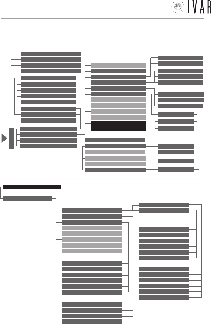
MAPA DE NAVEGACIÓN
[44]
LÍMITES
PREACTIVACIONES
DIAGNÓSTICOS
NOMBRE USUARIO
NUMERO ZONAS GESTIONADAS
RESET PARÁMETROS AVANZADOS
RESET TOTAL CRONOTERMÓSTATO
CONFIGURACIONES AVANZADAS*
INSTALACIÓN
T. CONFORT MÁX INVIERNO
T COMFORT MIN INVERNO
T. AHORRO MÁX INVIERNO
T. AHORRO MÍN INVIERNO
T. LÍMITE MÁX INVIERNO
T. LÍMITE MÍN INVIERNO
T. CONFORT MÁX VERANO
T. CONFORT MÍN VERANO
T. AHORRO MÁX VERANO
T. AHORRO MÍN VERANO
T. LÍMITE MÁX VERANO
T. LÍMITE MÍN VERANO
INVIERNO
VERANO
ANTICIPO MÁXIMO ARRANQUE
ANTICIPO MÁXIMO APAGADO
PRE-START AHORRO REDUCIDO
INDICE PRE-START CONFORT
DESVIACIÓN TPR MEMORIZADA
HISTORIAL ALARMAS
RESET ALLARMI
ACTIVAR MODALI. DIAGNÓSTICO
IDENTIFICAR ACTUADOR
IDENTIFICAR ZONA
CONFIGURACIΟN ÁREA
IDIOMA ACTUAL
PROGRAMACIÓN INVIERNO
PROGRAMACIÓN VERANO
ZONAS/REGULACIΟN VERANO
MODALIDAD VERANO/INVIERNO
FECHA
HORA
FORMATO HORA
UNIDADES DE MEDIDA TEMPERATURA
CONTRASTE
LUMINOSIDAD
OPTIMIZACIÓN ENCENDIDO
OPTIMIZACIÓN APAGADO
CONFIGURACIÓN NOMBRES ZONAS
MODALIDAD
CONFIGURACIONES
ASOCIACIONES
PREFERENCIAS
MODO MANUAL
MODO AUTOMÁTICO
MODO APAGADO
CONFIGURAR HORA
HORA LEGAL
CONFORT INVERNAL
AHORRO INVERNAL
LÍMITE INVERNAL
CONFORT VERANO
RISPARMIO ESTIVO
LÍMITE VERANO
ACTIVAR MODO MANUAL
MAN. 1 HORA
MAN. 2 HORAS
CONFIG. DURACIÓN M. MANUAL
APAGAR
APAGAR POR 1 HORA
APAGAR POR 2 HORAS
CONFIGURAR DURACIÓN APAGADO
ACTIVAR MODO AUTOMÁTICO
12 HORAS
24 HORAS
ZONA 1
NOMBRE ZONA 1
ZONA 1
L/M/M/J/V/S/D
GRÁFICO HORARIO
ASOCIACIÓN ZONA 1
M
E
N
Ú
BLOQUEO TECLAS
CONFIGURACIONES
AVANZADAS *
MAPA DE NAVEGACIÓN DE LAS FUNCIONES: a partir del MENÚ principal del cronotermostato (indicado con la flecha
de la figura), al cual se accede presionando la tecla MENÚ, seguir el esquema presente en esta página para ir a la
sección requerida.
Características y documentación sujetas a modificaciones sin obligación de previo aviso por parte del fabricante.
300546US-10-14
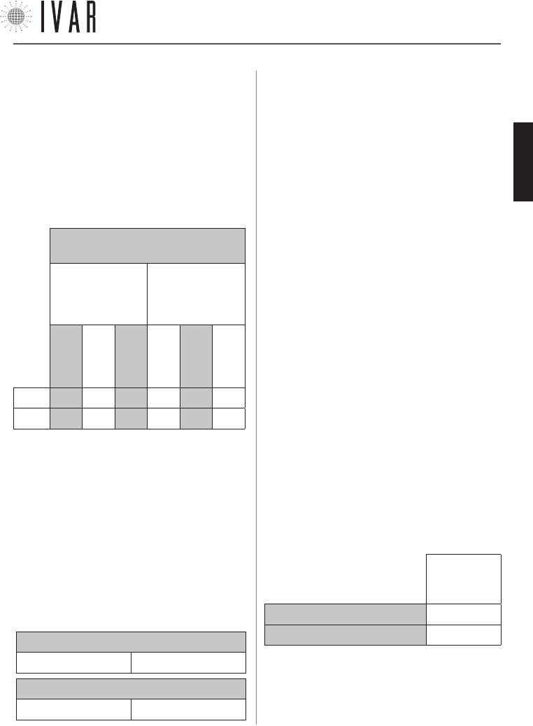
APÉNDICE
[45]
Características y documentación sujetas a modificaciones sin obligación de previo aviso por parte del fabricante.
TABLA 5: CAMPOS DE TEMPERATURA
(Predeterminado)
PROGRA-
MACIÓN
INVIERNO
PROGRA-
MACIÓN
VERANO
CONFORT
AHORRO
LÍMITE
CONFORT
AHORRO
LÍMITE
T MAX 77 °F 68 °F 59 °F 86 °F 95 °F 104 °F
T MIN 59 °F 50 °F 41 °F 68 °F 77 °F 86 °F
GESTION DE LAS CONFIGURACIONES DE TEMPERA-
TURA
Guía para la regulación
Remitirse a las siguientes indicaciones para gestionar
las configuraciones de temperatura (‘Programación
invierno’ y ‘Programación verano’).
El campo total de las temperaturas está dividido en 6
intervalos específicos, como se ilustra en la Tabla-5.
El ejemplo siguiente indica un modo posible de configu-
rar T1-T2-T3 in ‘Modalidad invierno’:
• Definir una temperatura CONFORT de 66 °F para la
opción Configurar confort invernal (T1).
• Posteriormente, definir una temperatura AHORRO
comprendida entre 50 °F y 66 °F para la opción Configu-
rar ahorro invernal (T2). T2 está, en efecto, subordinado
a T1; por ejemplo, definir 58 °F.
• T3 está, a su vez, subordinado a T2 y, en este caso
específico, se puede definir para la opción Configurar
límite invernal (T3) una temperatura LIMITE comprendi-
da entre 41 °F y 58 °F.
INTERACCIÓN DE LOS CAMPOS (INVIERNO)
CONFORT>AHORRO AHORRO>LIMITE
INTERACCIÓN DE LOS CAMPOS (VERANO)
CONFORT<AHORRO AHORRO<LIMITE
Cuando fuera necesario, redefinir el valor máximo y
mínimo de cada uno de los 6 campos de temperatura.
Por ejemplo:
1) Acceder a MENUàCONFIGURACIONESàCONFIGURACIONES
AVANZADASàINSTALACIÓNàLÍMITESàINVIERNOàTEMP. CON-
FORT MINIMA INVERNAL
y definir un valor de 68 °F. Después,
presionar CONFIRMAR.
2) Acceder a MENUàCONFIGURACIONESàCONFIGURACIONES
AVANZADASàINSTALACIÓNàLÍMITESàINVIERNOàTEMP. CON-
FORT MÁXIMA INVERNAL y definir un valor de 80 °F. Después,
presionar CONFIRMAR.
De este modo se obtiene un cam
-
po de CONFORT (12 °F de extensión) comprendido entre
68 °F y 80 °F. Es aconsejable que la dimensión de cada
campo no tenga una extensión menor a aprox. 3 °F.
Si, en efecto, ahora defino un valor de 70 °F para la
TEMP. CONFORT MÁXIMA INVERNAL, el sistema lleva
automáticamente la TEMP. CONFORT MÍNIMA INVERNAL
a 67 °F. El nuevo campo de CONFORT (aprox. 3 °F de
extensión) pasará de 67 °F a 70 °F.
REGULACIÓN DE LA FUNCIÓN ANTICONDENSACIÓN
En la instalación de los actuadores en algunos dispo-
sitivos puede ser necesario activar la función anticon-
densación, que se ejecuta oeprando en los mandos del
actuador. Un caso posible es la necesidad de excluir un
radiador de decoración del funcionamiento de verano.
Para regular esta función, configurar el Parámetro 2
(Acd) del actuador como se indica en la Tabla-6 (Ver
‘Configuraciones de las opciones del actuador’ de la pag.
42 para mayores detalles):
TABLA 6
VALOR DEL
PARAMETRO
‘ACD’
ANTICONDENSACIÓN ENCENDIDA B
ANTICONDENSACIÓN APAGADA C
NOTA: por defecto la función anticondensación está
apagada.
300546US-10-14
ESPAÑOL
300546US-10-14
300546US-10-14

300546US-10-14
WWW.IVAR-US.COM
EQUICALOR®
IT GB DE
FR ES DE
BE CZ NO