Ibm Version 5 Sy44 5902 05 Users Manual Service Functions V5R2
SY44-5902-05 to the manual 0945e368-abfc-4b38-ae18-49d03ccbc754
2015-02-02
: Ibm Ibm-Version-5-Sy44-5902-05-Users-Manual-431876 ibm-version-5-sy44-5902-05-users-manual-431876 ibm pdf
Open the PDF directly: View PDF ![]() .
.
Page Count: 358 [warning: Documents this large are best viewed by clicking the View PDF Link!]
- Contents
- Safety and Environmental Notices
- About Service Functions (SY44-5902-03)
- Chapter 1. Dedicated Service Tools (DST)
- Introduction
- System paging environments
- Accessing Dedicated Service Tools
- Performing an IPL to DST
- Changing a service tools user ID
- Resetting QSECOFR service tools user ID
- Performing an IPL to DST for secondary partitions
- Pressing the System Request Key while the system is operational
- Selecting Function 21 while the system Is operational
- Performing an alternate IPL to DST (type D IPL)
- Function keys (in DST)
- Exiting Dedicated Service Tools
- DST options
- Installing Licensed Internal Code
- Installing the operating system
- Perform an IPL
- Work with Licensed Internal Code
- Work with disk units
- Work with Dedicated Service Tools environment
- Start a service tool
- Perform automatic installation of the operating system
- Save Licensed Internal Code
- Work with save storage and restore storage
- Work with remote service support
- Work with system partitions
- Work with system capacity
- Work with system security
- Chapter 2. Hardware Service Manager
- Introduction
- Hardware Service Manager options
- Collecting information and performing functions from the Hardware Service Manager displays
- Change resource details
- Concurrent maintenance
- Create frame information
- Debug the resource
- Display address
- Display associated resources
- Display card gap information
- Display failed resources
- Display hardware contained within package
- Display location information
- Display non-reporting resources
- Display resources associated with IOP
- Display resource details
- Resource name
- Description
- Type-model
- Actual type-model
- Serial number
- Part number
- Miscellaneous text
- Location text
- Frame ID
- EIA location
- Card position
- Device position
- Height in EIA units
- Width in mm
- Manufacturing ID
- Actual manufacturing ID
- Alternate remote telephone
- Alternate service node
- Alternate service telephone
- Service provider
- Manufactured by IBM
- Shared by multiple systems
- Display resources requiring attention
- Display resource status
- Display serial/part numbers, logical address, and status/resource name information
- Display system bus resources
- Display system information
- Display unresolved locations
- Refresh the display
- Remove non-reporting resource information
- Reserve frame space
- Using High-Speed Link (HSL) specific options
- Verify resources
- Symbols on the Hardware Service Manager displays
- Printing the System Configuration List
- Verification procedures
- Chapter 3. Product Activity Log
- Chapter 4. Service Reference Procedures
- Setting the system date and time
- Determining the dominant operating system
- System password
- System unique identifier
- Determining a primary or alternative console
- Locating the system's load source from the system console
- History file
- Continuously Powered Main Storage (CPM)
- Low-level debug and data collecting procedures
- Introduction
- Getting started
- Displaying data for functions 54 through 58, 63, and 64 (Models 150, 170, 250, 4xx, 50x, 51x, 530, 53S, 6xx, 7xx, SB1, and Sxx)
- Displaying data for functions 57, 63, and 64 (Models 270, 8xx, SB2, SB3, and 890)
- Changing the address in functions 59 through 61 (Models 150, 170, 250, 4xx, 50x, 51x, 530, 53S, 6xx, 7xx, SB1, and Sxx)
- Changing the address in functions 58 through 61 (Models 270, 8xx, SB2, SB3, and 890)
- Displaying data from function 62
- Logical partitions
- Examples: Missing or non-reporting system bus resources
- Determining the release level of a logical partition
- Locating a secondary partition's console
- Locating a secondary partition's load source
- Locating a secondary partition's load source from the secondary partition's console
- Locating a secondary partition's load source from the primary partition's console
- Querying logical partition time and date
- Converting secondary partition time and date to primary partition time and date
- Finding the SRC history list for a secondary partition
- Closing related problems in other logical partitions
- Accessing the panel functions of a logical partition
- Determining which logical partition owns a FRU or a system I/O resource
- Selecting IPL source and mode for a secondary partition
- Options on the Work with Partition Status display
- Guest partitions
- IASP/Clustering Service Reference Procedures
- Chapter 5. Control Panel Functions
- Values for IPL types, key modes, and speeds
- Control Panel Functions (Models 150, 170, 250, 4xx, 50x, 51x, 530, 53S, 6xx, 7xx, SB1, and Sxx)
- Ways to access the control panel (Models 150, 170, 250, 4xx, 50x, 51x, 530, 53S, 6xx, 7xx, SB1, and Sxx)
- Control panel function descriptions (Models 150, 170, 250, 4xx, 50x, 51x, 530, 53S, 6xx, 7xx, SB1, and Sxx)
- Customer control panel functions (Models 150, 170, 250, 4xx, 50x, 51x, 530, 53S, 6xx, 7xx, SB1, and Sxx)
- Extended control panel functions (Models 150, 170, 250, 4xx, 50x, 51x, 530, 53S, 6xx, 7xx, SB1, and Sxx)
- Low-Level Debug (LLD) panel functions (Models 150, 170, 250, 4xx, 50x, 51x, 530, 53S, 6xx, 7xx, SB1, and Sxx)
- Control panel functions (Models 270, 8xx, SB2, SB3, and 890)
- Chapter 6. System Reference Code (SRC) Information
- Chapter 7. Initial Program Load (IPL) Information
- Chapter 8. Licensed Internal Code
- Chapter 9. System Architecture and Configuration
- Hardware information
- System power overview
- Power supply
- Battery power unit
- System Power Control Network (SPCN)
- SPCN menu flow
- Battery capacity test
- Opt
- Frame
- Unit
- Type
- Serial number
- Fault
- Write Vital Product Data (VPD) option
- Display Detail option
- Frame
- Type
- Model
- Serial number
- Load ID
- Reference code
- Alert status
- Extended status
- AROS part number
- Responding to polls
- Primary frame
- Power sequence complete
- Fault
- UEPO switch
- Cable type for connector J15
- Cable type for connector J16
- Cable type for connector J18
- Frame
- Unit
- Type
- Model
- Serial number
- Load ID
- Reference code
- Alert status
- Extended status
- AROS part number
- Battery present
- Last battery capacity test date
- Last battery capacity test time
- Next battery capacity test date
- Next battery capacity test time
- Power sequence complete
- Fault
- Display trace log
- Test battery option
- System Interconnect
- High Speed Link
- Multi-adapter bridge
- Resource names
- Hardware configuration restrictions
- Communications card, cable, and wrap connector reference
- Single-port communications adapter card and TPAC wrap connector
- High speed communications card and wrap connector wiring
- Advanced PCI communications console cable
- Cryptographic processor card and wrap connector wiring
- Two-port communications adapter card and wrap connector wiring
- ISDN wrap connector and connector pin
- Two-port communications adapter cable
- RJ-45 cable wrap connector
- V.24 communications adapter remote power-on cable
- V.24/X.21bis communications adapter cable
- Stage 1 V.24/X.21bis cable wrap connector wiring
- V.24/X.21bis cable wrap connector wiring
- EIA 232 advanced PCI communications cable
- EIA 232 advanced wrap connector wiring
- Stage 1 EIA-232/X.21bis communications adapter cable
- EIA-232/X.21bis communications adapter cable
- EIA-232/X.21bis cable wrap connector wiring
- V.36/EIA 449 high speed communications adapter cable
- V.36/EIA 449 high speed communications adapter cable wrap connector wiring
- Stage 1 V.35 communications adapter cable
- Stage 1 V.35 cable wrap connector wiring
- V.24 advanced PCI communications cable
- V.24 advanced wrap connector wiring
- V.35 advanced PCI communications cable
- V.35 advanced wrap connector wiring
- V.35 communications adapter cable
- V.35 cable wrap connector wiring
- V.35/High speed communications adapter cable
- V.35/High speed communications adapter cable wrap connector wiring
- V.36/RS-449 advanced PCI communications cable
- V.36/RS-449 advanced cable wrap connector wiring
- X.21 communications adapter cable
- X.21/High speed communications adapter cable
- X.21 cable wrap connector wiring
- X.21 advanced PCI communications cable
- X.21 advanced wrap connector wiring
- Token-ring communications adapter cable and card wrap
- Ethernet/IEEE 802.3 transceiver adapter cable and card wrap
- Facsimile adapter cable wrap connector wiring
- DDI transceiver adapter cable and card wrap
- PCI communications card wrap connector wiring
- Communications signal voltage levels
- Chapter 10. Working with Storage Dumps
- Main storage dump introduction
- Automatic main storage dump
- Performing a main storage dump to disk (manual MSD)
- Copying a main storage dump
- Main storage dump status
- Error recovery for dumps
- Performing an IOP storage dump to disk (Models 150, 170, 250, 4xx, 50x, 51x, 530, 53S, 6xx, 7xx, SB1, S20, S30, and S40)
- Performing a service processor storage dump (Models 270, 8xx, SB2, SB3, and 890)
- Copying the IOP storage dump to removable media (All Models)
- Copying the service processor storage dump to removable media (Models 270, 8xx, SB2, SB3, and 890)
- Performing an IOP dump using hardware service manager (All Models)
- IOP dump information in the Product Activity Log (All Models)
- Appendix A. OS/400 Operating System
- DST in OS/400 full paging environment
- DST in OS/400 limited paging environment
- System Service Tools (SST)
- Online problem analysis and resolution
- Displaying OS/400 PTFs
- OS/400 or LIC APAR information
- How to reset an I/O processor card while the system is up and running
- Varying configuration descriptions on and off
- Commonly used OS/400 service commands
- Verify commands
- Communications tests
- Appendix B. Notices
- Glossary of Terms and Abbreviations
- Index
- Readers’ Comments — We'd Like to Hear from You

iSeries
Service Functions
Version 5
SY44-5902-05
ERserver
iSeries
Service Functions
Version 5
SY44-5902-05
ER s e r v e r

Note
Before using this information and the product it supports, be sure to read the information in
“Safety and Environmental Notices” on page vii and Appendix B, “Notices” on page 321.
Sixth Edition (August 2002)
This edition applies to version 5, release 2, modification 0 of Service Functions manual (SY44–5902–05) and to all
subsequent releases and modifications until otherwise indicated in new editions. This edition applies only to
reduced instruction set computer (RISC) systems.
© Copyright International Business Machines Corporation 1997, 2002. All rights reserved.
US Government Users Restricted Rights – Use, duplication or disclosure restricted by GSA ADP Schedule Contract
with IBM Corp.

Contents
Safety and Environmental Notices . . . vii
Danger Notices .............vii
Product Recycling and Disposal .......viii
Battery Return Program ..........viii
Environmental Design ..........viii
Caution Notices ............viii
Attention Notices ............ix
Laser Safety Information ..........x
Laser Safety Information (for IBM Fiber Optic
Link Products).............x
About Service Functions (SY44-5902-03) xi
Who should read this book .........xi
Conventions and terminology used in this book . . xi
Prerequisite and related information ......xi
iSeries Navigator ...........xii
How to send your comments ........xii
Chapter 1. Dedicated Service Tools
(DST)................1
Introduction ..............1
DedicatedServiceToolsrequirements.....1
System paging environments .........2
Stand-alone paging (non-paging) ......2
Limited paging ............2
Full paging ..............3
Accessing Dedicated Service Tools .......4
Performing an IPL to DST .........4
Changing a service tools user ID.......5
Resetting QSECOFR service tools user ID....6
Performing an IPL to DST for secondary partitions 6
Pressing the System Request Key while the system
is operational .............7
Selecting Function 21 while the system Is
operational ..............7
Performing an alternate IPL to DST (type D IPL) . 8
Function keys (in DST) ...........9
Exiting Dedicated Service Tools........10
DSToptions..............10
Installing Licensed Internal Code ......11
Installing the operating system .......11
Perform an IPL ............11
Work with Licensed Internal Code......11
Workwithdiskunits..........13
Work with Dedicated Service Tools environment 23
Start a service tool ...........28
Perform automatic installation of the operating
system ...............39
Save Licensed Internal Code........40
Work with save storage and restore storage. . . 40
Work with remote service support ......40
Work with system partitions........42
Work with system capacity ........42
Work with system security ........42
Chapter 2. Hardware Service Manager 45
Introduction ..............45
Hardware Service Manager options ......46
Packaging hardware resources .......47
Logicalhardwareresources........49
Locateresourcebyname.........50
Failed and non-reporting resources .....53
System Power Control Network (SPCN) ....55
Battery power unit information .......55
Work with service action log .......56
Displaylabellocationworksheet......58
Device concurrent maintenance.......58
Collecting information and performing functions
from the Hardware Service Manager displays . . . 61
Change resource details .........61
Concurrent maintenance .........63
Createframeinformation.........64
Debugtheresource...........66
Display address ............67
Displayassociatedresources........67
Displaycardgapinformation.......69
Displayfailedresources.........70
Display hardware contained within package . . 70
Displaylocationinformation........71
Display non-reporting resources ......71
DisplayresourcesassociatedwithIOP....72
Displayresourcedetails.........73
Display resources requiring attention .....77
Displayresourcestatus.........78
Display serial/part numbers, logical address, and
status/resourcenameinformation......79
Display system bus resources .......79
Display system information ........82
Displayunresolvedlocations .......82
Print................83
Refreshthedisplay...........83
Remove non-reporting resource information . . 83
Reserve frame space ..........84
Using High-Speed Link (HSL) specific options. . 84
Verify resources ............92
Symbols on the Hardware Service Manager displays 93
Printing the System Configuration List .....93
Verification procedures ..........95
Hardware Service Manager —Verify .....95
Verify optical storage unit ........96
Verify diskette ............96
Verify tape..............96
Verify communications .........97
Chapter 3. Product Activity Log ....99
Introduction ..............99
Product Activity Log (PAL).........100
The Service Action Log (SAL) .......100
Product Activity Log location .......101
© Copyright IBM Corp. 1997, 2002 iii
Recovering from Product Activity Log errors
whileinDST............101
Paging environment ...........101
Options and function keys .........102
Analyze log .............102
DisplayorprintbylogID........103
Change Product Activity Log sizes .....104
Work with removable media lifetime statistics 104
Display or print removable media session
statistics ..............105
Sort by ... function...........105
Address information function .......106
View description function ........107
Hexadecimal Product Activity Log data . . . 107
Interpreting Product Activity Log reports ....110
Some considerations when interpreting Product
Activity Log reports ..........110
Resourcename............111
Resourcetype,model,andlocation.....112
Class...............112
System reference code .........113
Multiple SRC entries ..........114
Logical address format .........114
Sequencenumber...........115
Secondary code............115
TableID..............115
IPLsource/state...........115
Hexadecimal report ..........115
Chapter 4. Service Reference
Procedures ............125
Setting the system date and time .......125
Determining the dominant operating system . . . 126
System password ............126
System unique identifier..........127
Determining a primary or alternative console. . . 128
Introduction .............128
Primaryconsolerequirements.......128
Identifying the consoles when the system is
operational .............128
Locating the system’s load source from the system
console...............129
History file ..............130
Continuously Powered Main Storage (CPM) . . . 131
Low-level debug and data collecting procedures 131
Introduction .............131
Getting started ............131
Displaying data for functions 54 through 58, 63,
and 64 (Models 150, 170, 250, 4xx, 50x, 51x, 530,
53S, 6xx, 7xx, SB1, and Sxx) .......131
Displaying data for functions 57, 63, and 64
(Models 270, 8xx, SB2, SB3, and 890) ....132
Changing the address in functions 59 through
61 (Models 150, 170, 250, 4xx, 50x, 51x, 530, 53S,
6xx, 7xx, SB1, and Sxx) .........133
Changing the address in functions 58 through
61 (Models 270, 8xx, SB2, SB3, and 890) . . . 135
Displaying data from function 62......136
Logical partitions ............136
Examples: Missing or non-reporting system bus
resources..............137
Determining the release level of a logical
partition ..............138
Locating a secondary partition’s console . . . 138
Locating a secondary partition’s load source . . 139
Locating a secondary partition’s load source
from the secondary partition’sconsole....139
Locating a secondary partition’s load source
from the primary partition’sconsole.....140
Querying logical partition time and date . . . 141
Converting secondary partition time and date to
primary partition time and date ......141
Finding the SRC history list for a secondary
partition ..............141
Closing related problems in other logical
partitions ..............141
Accessing the panel functions of a logical
partition ..............142
Determining which logical partition owns a
FRU or a system I/O resource.......142
Selecting IPL source and mode for a secondary
partition ..............143
Options on the Work with Partition Status
display..............143
Guest partitions ...........147
IASP/Clustering Service Reference Procedures . . 149
Determining if a tower is configured as
switchable .............149
Determining the power controlling system of a
tower...............150
Determining the resource name and HSL loop
numberofanHSLI/Obridge.......152
Switching ownership of a tower’s switchable
resources..............154
Switching the mode of a tower’s switchable
resources..............156
Chapter 5. Control Panel Functions 159
Values for IPL types, key modes, and speeds . . . 159
Control Panel Functions (Models 150, 170, 250, 4xx,
50x, 51x, 530, 53S, 6xx, 7xx, SB1, and Sxx) ....160
Ways to access the control panel (Models 150,
170, 250, 4xx, 50x, 51x, 530, 53S, 6xx, 7xx, SB1,
and Sxx) ..............162
Control panel function descriptions (Models 150,
170, 250, 4xx, 50x, 51x, 530, 53S, 6xx, 7xx, SB1,
and Sxx) ..............162
Control panel functions (Models 270, 8xx, SB2, SB3,
and 890) ...............174
Ways to access the control panel (Models 270,
8xx, SB2, SB3, and 890) .........175
Control panel function descriptions (Models 270,
8xx, SB2, SB3, and 890) .........177
Chapter 6. System Reference Code
(SRC) Information .........191
Introduction ..............191
SRCformats..............191
Word1-SRCgeneralinformation.....193
Word 2 - System status information .....194
System Reference Codes (SRCs) .......196
iv Service Functions V5R2
General system and Unit Reference Code (URC)
information.............196
SPCN informational concurrent maintenance
SRCs ...............201
IPL status SRCs ...........201
General status SRCs ..........214
Chapter 7. Initial Program Load (IPL)
Information ............217
IPLtype,mode,andspeedoptions......217
IPLspeedrecommendations.......217
Methods to perform IPL..........217
Alternate installation IPL .........218
IPLsequence.............218
Service processor initialization.......218
Licensed Internal Code (LIC) initialization. . . 219
Status SRCs ..............221
Chapter 8. Licensed Internal Code 223
Licensed Internal Code (LIC) introduction ....223
Fixes and cumulative PTF packages ......223
Cumulative PTF packages ........224
PSP listings .............224
Licensed programs ..........224
Displaying Licensed Internal Code fixes ....224
Code naming conventions .........225
Utilities to Install and Restore Licensed Internal
Code ................225
Introduction .............225
Overview of Licensed Internal Code Install and
Restore ..............225
Utility to install Licensed Internal Code . . . 226
Utility to restore Licensed Internal Code . . . 227
Authorized Program Analysis Report (APAR) . . 228
Chapter 9. System Architecture and
Configuration ...........229
Hardwareinformation..........230
System power overview ..........230
Power supply ............230
Battery power unit ..........230
System Power Control Network (SPCN) . . . 231
SPCN menu flow ...........232
System Interconnect ...........241
HighSpeedLink............241
Multi-adapter bridge ...........242
Resourcenames ............242
Hardware configuration restrictions ......244
Communications card, cable, and wrap connector
reference ...............244
Single-port communications adapter card and
TPAC wrap connector .........244
High speed communications card and wrap
connector wiring ...........245
Advanced PCI communications console cable 246
Cryptographic processor card and wrap
connector wiring ...........246
Two-port communications adapter card and
wrap connector wiring .........247
ISDN wrap connector and connector pin . . . 248
Two-port communications adapter cable . . . 249
RJ-45 cable wrap connector ........251
V.24 communications adapter remote power-on
cable...............251
V.24/X.21bis communications adapter cable . . 252
Stage 1 V.24/X.21bis cable wrap connector
wiring ...............253
V.24/X.21bis cable wrap connector wiring . . . 253
EIA 232 advanced PCI communications cable 253
EIA 232 advanced wrap connector wiring . . . 254
Stage 1 EIA-232/X.21bis communications
adapter cable ............254
EIA-232/X.21bis communications adapter cable 255
EIA-232/X.21bis cable wrap connector wiring 255
V.36/EIA 449 high speed communications
adapter cable ............256
V.36/EIA 449 high speed communications
adapter cable wrap connector wiring ....256
Stage 1 V.35 communications adapter cable . . 257
Stage 1 V.35 cable wrap connector wiring . . . 257
V.24 advanced PCI communications cable . . . 257
V.24 advanced wrap connector wiring ....258
V.35 advanced PCI communications cable . . . 258
V.35 advanced wrap connector wiring ....259
V.35 communications adapter cable .....260
V.35 cable wrap connector wiring......260
V.35/High speed communications adapter cable 260
V.35/High speed communications adapter cable
wrap connector wiring .........261
V.36/RS-449 advanced PCI communications
cable...............261
V.36/RS-449 advanced cable wrap connector
wiring ...............262
X.21 communications adapter cable .....263
X.21/High speed communications adapter cable 263
X.21 cable wrap connector wiring .....263
X.21 advanced PCI communications cable . . . 263
X.21 advanced wrap connector wiring ....264
Token-ring communications adapter cable and
cardwrap.............264
Ethernet/IEEE 802.3 transceiver adapter cable
andcardwrap............264
Facsimile adapter cable wrap connector wiring 265
DDI transceiver adapter cable and card wrap 265
PCI communications card wrap connector
wiring ...............266
Communications signal voltage levels .....267
Chapter 10. Working with Storage
Dumps..............269
Main storage dump introduction .......269
Automaticmainstoragedump .......270
Performing a main storage dump to disk (manual
MSD)................271
Copying a main storage dump .......272
Workwithcurrentmainstoragedump....273
Work with copies of main storage dumps . . . 274
Mainstoragedumpstatus.........275
Terminating System Reference Code (SRC) . . 275
Errorrecoveryfordumps.........276
Contents v
Determining whether main storage dump data
was written to disk ..........276
Reporting the error ..........276
Additional help ...........277
Performing an IOP storage dump to disk (Models
150, 170, 250, 4xx, 50x, 51x, 530, 53S, 6xx, 7xx, SB1,
S20, S30, and S40) ............277
Performing a service processor storage dump
(Models 270, 8xx, SB2, SB3, and 890) .....277
Copying the IOP storage dump to removable
media (All Models) ...........278
Copying the service processor storage dump to
removable media (Models 270, 8xx, SB2, SB3, and
890) ................278
Performing an IOP dump using hardware service
manager (All Models) ..........279
IOP dump information in the Product Activity Log
(All Models)..............279
Appendix A. OS/400 Operating System 281
DST in OS/400 full paging environment ....281
DST in OS/400 limited paging environment . . . 282
System Service Tools (SST) .........282
Accessing system service tools.......282
SSToptions.............283
Function keys (SST) ..........289
Online problem analysis and resolution ....290
Introduction .............290
System-detected problems ........290
Customer-detected problems .......292
Service support facility .........293
Displaying OS/400 PTFs .........293
OS/400 or LIC APAR information ......293
How to reset an I/O processor card while the
system is up and running .........295
Varying configuration descriptions on and off . . 295
Commonly used OS/400 service commands . . . 296
Work with System Value (WRKSYSVAL)
Command.............298
Service attributes (DSPSRVA or CHGSRVA)
commands .............299
Change Transmit Level (CHGXMTLVL)
command .............301
Work with Hardware Products (WRKHDWPRD)
Command.............302
Verify commands ............308
Commonly used verify commands .....308
Verify communications .........308
Communicationstests..........316
Wireless LAN adapter card indicators ....316
Communications interface trace ......316
Concurrent LPDA-2 tests ........317
Appendix B. Notices ........321
Trademarks..............322
Glossary of Terms and Abbreviations 325
Index ...............331
vi Service Functions V5R2

Safety and Environmental Notices
Danger Notices
A danger notice calls attention to a situation that is potentially lethal or extremely
hazardous to people.
DANGER
To prevent power from switching on automatically during service procedures,
select manual or secure mode on the system unit control panel or disconnect
the cables that connect to J15 and J16 on the frame being serviced.
(RSFTD211)
DANGER
An electrical outlet that is not correctly wired could place hazardous voltage
on metal parts of the system or the products that attach to the system. It is the
customer’s responsibility to ensure that the outlet is correctly wired and
grounded to prevent an electrical shock. (RSFTD201)
DANGER
To prevent a possible electrical shock when installing the system, ensure that
the power cords for all devices are unplugged before installing signal cables.
(RSFTD202)
DANGER
To prevent a possible electrical shock when adding or removing any devices
to or from the system, ensure that the power cords for those devices are
unplugged before the signal cables are connected or disconnected. If possible,
disconnect all power cords from the existing system before you add or
remove a device. (RSFTD203)
DANGER
Use caution when installing or modifying telephone lines. Disconnect the
lines at the network interface before working with telephone wires that are
not insulated. Never install telephone jacks that are not waterproof in wet
locations. Do not install or modify telephone lines or use a telephone (other
than a cordless type) during an electrical storm. Do not use a telephone to
report a gas leak in the area of the leak. (RSFTD213)
DANGER
To prevent a possible electrical shock during an electrical storm, do not
connect or disconnect cables or station protectors for communications lines,
display stations, printers, or telephones. (RSFTD003)
© Copyright IBM Corp. 1997, 2002 vii

DANGER
To prevent a possible electrical shock from touching two surfaces with
different electrical grounds, use one hand, when possible, to connect or
disconnect signal cables. (RSFTD004)
DANGER
To prevent a possible electrical shock, do not use the port tester during
electrical storms. (RSFTD006)
Product Recycling and Disposal
Components of the system, such as structural parts and circuit cards, can be
recycled where recycling facilities exist. IBM does not currently collect and recycle
used IBM products from customers in the United States other than those products
that are involved in trade-in programs. Companies are available to disassemble,
reutilize, recycle, or dispose of electronic products. Contact an IBM account
representative for more information.
The system unit contains batteries and circuit boards with lead solder. Before you
dispose of this unit, these batteries and circuit boards must be removed and
discarded according to local regulations or recycled where facilities exist. This book
contains specific information on each battery type where applicable.
Battery Return Program
In the United States, IBM has established a collection process for reuse, recycling,
or proper disposal of used IBM batteries and battery packs. For information on
proper disposal of the batteries in this unit, please contact IBM at 1-800-426-4333.
Please have the IBM part number that is listed on the battery available when you
make your call. For information on battery disposal outside the United States,
contact your local waste disposal facility.
Environmental Design
The environmental efforts that have gone into the design of the system signify
IBM’s commitment to improve the quality of its products and processes. Some of
these accomplishments include the elimination of the use of Class I
ozone-depleting chemicals in the manufacturing process, reductions in
manufacturing wastes, and increased product energy efficiency. For more
information, contact an IBM account representative.
Caution Notices
A caution notice calls attention to a situation that is potentially hazardous to
people because of some existing condition.
CAUTION:
Be careful when removing or installing this part or unit. This part or unit is
heavy, but has a weight smaller than 18 kilograms (39.7 pounds). (RSFTC201)
CAUTION:
The weight of this part or unit is between 18 and 32 kilograms (39.7 and 70.5
pounds). It takes two persons to safely lift this part or unit. (RSFTC204)
viii Service Functions V5R2

CAUTION:
The battery is a lead-acid battery. To avoid possible explosion, do not burn.
Exchange only with the IBM-approved part. Recycle or discard the battery as
instructed by local regulations.
In the United States, IBM has a process for the collection of this battery. For
information, call 1-800-426-4333. Have the IBM part number for the battery unit
available when you call. (RSFTC225)
CAUTION:
The circuit card contains lead solder. To avoid the release of lead (Pb) into the
environment, do not burn. Discard the circuit card as instructed by local
regulations. (RSFTC234)
CAUTION:
This assembly has a circuit card that contains lead solder. To avoid the release of
lead (Pb) into the environment, do not burn. Discard the assembly as instructed
by local regulations. (RSFTC235)
CAUTION:
The optical link card contains a laser. To avoid the release of toxic substances
into the environment, do not burn. Discard the optical link as instructed by local
regulations. (RSFTC236)
CAUTION:
The battery is a lithium battery. To avoid possible explosion, do not burn or
charge the battery. Exchange only with the IBM-approved part. Discard the
battery as instructed by local regulations. (RSFTC227)
Attention Notices
An attention notice indicates the possibility of damage to a program, device,
system, or data.
Safety and Environmental Notices ix

Laser Safety Information
Laser Safety Information (for IBM Fiber Optic Link Products)
CAUTION:
This system may contain laser products called the IBM Optical Link Module
(OLM), Serial Optical Converter (SOC), or Optical Link Card (OLC). In the
United States, these fiber optic links are certified by IBM as Class I laser
products that conform to the requirements contained in the Department of
Health and Human Services (DHHS) regulation 21 CFR Subchapter J.
Internationally, these fiber optic links are certified as Class 1 laser products that
conform to the requirements contained in the International Electrotechnical
Commission (IEC) standard 825-1 (1993), the CENELEC (European Committee for
Electrotechnical Standardization) European Norm standard EN60825-1 (1994), and
the Verband Deutscher Elektrotechniker (VDE) standard 0837 (1986). The
German testing institute, VDE, has assigned certificate registration number 3642
to all IBM OLM, SOC, and OLC laser products.
The fiber optic links incorporate laser diodes that are either of the gallium
aluminum arsenide (GaAlAs) type that emits in the wavelength range of 770 to
860 nanometers or of the indium gallium arsenide phosphide (InGaAsP) type
that emits in the wavelength range of 1270 to 1355 nanometers. These fiber optic
links incorporate discrete laser diodes that are Class 3B laser products with a
rating of approximately 5.0 milliwatts peak power. Once the lasers are
assembled into the OLM, SOC, or OLC, the automatic laser control safety system
prevents laser emissions from exceeding Class 1 limits during both operation
and service. There are no user maintenance operations or adjustments to be
performed on IBM OLM, SOC, or OLC products. Class 1 laser products are not
considered to be hazardous under any conditions.
The fiber optic links are designed and certified for use in applications with
point-to-point optical links only. Use of these products with multiple input or
multiple output links (for example, star coupler or fiber splitter) is not
compatible with the OLM, SOC, or OLC design and function. In addition, the
fiber optic link products must be connected only to other IBM OLM, SOC, or
OLC (of the same model) or a compatible laser product. This is especially true
for those models that contain both the open link detection safety system called
Open Fiber Control (OFC) and the laser power control safety system. (All OLM,
SOC, and OLC models contain the laser power control safety system. All OLC
models contain OFC, all SOC model have No-OFC, but some OLM models are
available with OFC and some have No-OFC.)
These requirements are necessary for the correct operation of the IBM OLM,
SOC, and OLC products in any optical communication system. Failure to follow
these restrictions could result in the system not operating correctly and the
creation of points of access that emit laser radiation above the Class 1 limit
specified by either the IEC 825-1 (1993) standard internationally or the DHHS
regulation 21 CFR Sub J in the United States. (RSFTC211)
xService Functions V5R2

About Service Functions (SY44-5902-03)
This book provides basic information about iSeries functions that are commonly
used by field hardware service representatives. It provides enough detail for the
hardware service representative to gather information about hardware problems
while under the direction of the next level of support.
The book is meant to assist the hardware service representative in gathering
information about commonly encountered field problems. It does not cover all
service functions available on the iSeries.
Who should read this book
This book is intended for trained iSeries hardware service representatives and
service providers who act as the primary level of field hardware service support
(as opposed to system operators) to help solve and diagnose hardware problems.
Before using this book, you should know how to service (analyze, isolate, report,
and resolve problems, and verify fixes using the iSeries maintenance package) the
iSeries hardware. You must also know how to safely work with electrical
components.
Attention: Some service tools described in this book can be used to change or
erase data, programs, or other objects on the iSeries system. This damage can occur
with the misuse of service tools or with inappropriate security in effect.
Conventions and terminology used in this book
This book contains examples of displays that are illustrated as completely as
possible; however, they may vary from those you actually use.
Before using this information and the product it supports, be sure to read the
general information and danger notices under Appendix B, “Notices”on page 321.
Refer to the Glossary for terms not explained in the text.
Throughout this book, the terms iSeries applies to any iSeries System Model Unit,
unless the reference is to a specific model.
Prerequisite and related information
Use the iSeries Information Center as your starting point for looking up iSeries
technical information. You can access the Information Center from the following
Web site::
vhttp://www.ibm.com/eserver/iseries/infocenter
The iSeries Information Center contains advisors and important topics such as CL
commands, system application programming interfaces (APIs), logical partitions,
clustering, Java, TCP/IP, Web serving, and secured networks. It also includes links
to related IBM Redbooks and Internet links to other IBM Web sites such as the
Technical Studio and the IBM home page.
With every new hardware order, you receive the following CD-ROM information:
© Copyright IBM Corp. 1997, 2002 xi

vThe iSeries Setup and Operations CD-ROM. This CD-ROM contains IBM iSeries
Access for Windows and the EZ-Setup wizard. iSeries Access for Windows offers
a powerful set of client and server capabilities for connecting PCs to iSeries
servers. The EZ-Setup wizard automates many of the iSeries setup tasks.
iSeries Navigator
IBM iSeries Navigator is a powerful graphical interface for managing your iSeries
and AS/400e servers. iSeries Navigator functionality includes system navigation,
configuration, planning capabilities, and online help to guide you through your
tasks. iSeries Navigator makes operation and administration of the server easier
and more productive and is the only user interface to the new, advanced features
of the OS/400 operating system. It also includes Management Central folder within
iSeries Navigator for managing multiple servers from a central server.
For more information on iSeries Navigator, see the iSeries Information Center.
How to send your comments
Your feedback is important in helping to provide the most accurate and
high-quality information. If you have any comments about this book or any other
iSeries documentation, fill out the readers’comment form at the back of this book.
vIf you prefer to send comments by mail, use the readers’comment form with the
address that is printed on the back. If you are mailing a readers’comment form
from a country or region other than the United States, you can give the form to
the local IBM branch office or IBM representative for postage-paid mailing.
vIf you prefer to send comments by FAX, use either of the following numbers:
–United States, Canada, and Puerto Rico: 1-800-937-3430
–Other countries: 1-507-253-5192
vIf you prefer to send comments electronically, use one of these e-mail addresses:
–Comments on books:
RCHCLERK@us.ibm.com
–Comments on the iSeries Information Center:
RCHINFOC@us.ibm.com
Be sure to include the following:
vThe name of the book or iSeries Information Center topic.
vThe publication number of a book.
vThe page number or topic of a book to which your comment applies.
xii Service Functions V5R2

Chapter 1. Dedicated Service Tools (DST)
Introduction ..............1
DedicatedServiceToolsrequirements.....1
System paging environments .........2
Stand-alone paging (non-paging) ......2
Limited paging ............2
Full paging ..............3
Accessing Dedicated Service Tools .......4
Performing an IPL to DST .........4
Changing a service tools user ID.......5
Resetting QSECOFR service tools user ID....6
Performing an IPL to DST for secondary partitions 6
Pressing the System Request Key while the system
is operational .............7
Selecting Function 21 while the system Is
operational ..............7
Performing an alternate IPL to DST (type D IPL) . 8
Function keys (in DST) ...........9
Exiting Dedicated Service Tools........10
DSToptions..............10
Installing Licensed Internal Code ......11
Installing the operating system .......11
Perform an IPL ............11
Work with Licensed Internal Code......11
Licensed Internal Code general information . 12
Options and function keys .......12
Workwithdiskunits..........13
Options on the Work with Disk Units Display 14
Work with Dedicated Service Tools environment 23
Work with active service tools ......24
Work with system devices .......25
Work with service tools user IDs .....25
Workwithsystemvalues........26
Work with alternate installation device . . . 27
Select DST console mode ........27
Start a service tool ...........28
Options on the Start a Service Tool display . . 28
Perform automatic installation of the operating
system ...............39
Save Licensed Internal Code........40
Work with save storage and restore storage. . . 40
Work with remote service support ......40
Allowing access for remote service support. . 41
Activating remote service support .....41
Work with system partitions........42
Work with system capacity ........42
Work with system security ........42
Introduction
Dedicated service tools (DST) is used to service Licensed Internal Code (LIC), work
with disk units, work with configuration and resources, verify devices and
communications, and display logs on the system.
DST operates in stand-alone, limited, and full paging environments. The DST tools
and functions vary depending on the paging environment and the release level of
the operating system. For more information, see “System paging environments”on
page 2.
System Service Tools (SST) provides a way to access a subset of the service tools
that DST offers without requiring access to DST. SST is available when OS/400 is
operational, and can be accessed using the STRSST CL command.
Dedicated Service Tools requirements
Attention: It is a requirement to change the password the first time anyone signs
on to DST or SST. The customer engineer needs to give the new (changed)
password to the customer or have the customer change the password.
To use DST, you must have the following items:
vThe disk that contains the Licensed Internal Code (the load-source disk).
Note: When you perform an alternate initial program load (IPL) to DST, you do
not need the load-source disk.
vAn operational workstation on bus 1 as either a primary console or an
operations console.
© Copyright IBM Corp. 1997, 2002 1

vOne workstation for each system partition.
vA valid service tools user ID and password to sign on to DST. IBM supplies
service tools user IDs that have different levels of privileges. See “Work with
service tools user IDs”on page 25 for more information.
To make a printout, attach the printer to the workstation I/O processor or storage
media unit that is performing the service function. The printer that is used with
DST for service tool output must be an SCS-type data stream printer (for example,
type 5224).
System paging environments
The amount of assistance that software provides for service depends on how you
perform the system IPL. The service tools and functions that are available depend
on how you access DST and which operating system is in use. Service
environments for the system are:
vStand-alone (also called non-paging)
vLimited paging
vFull paging
Stand-alone paging (non-paging)
You can reach this environment only by performing an alternate IPL to DST (see
“Performing an alternate IPL to DST (type D IPL)”on page 8).
You can access dedicated service tools (DST) while the system is in the stand-alone
paging environment, but not all DST options are available. In this environment, no
operating system is available, and only some functions of Licensed Internal Code
are operational.
The following options are available in the stand-alone environment for all
operating systems:
vInstall Licensed Internal Code
vWork with disk units
vWork with DST environment
vStart a service tool
vWork with remote service support
For a description of each option, see “DST options”on page 10.
Attention: Performing an IPL on the primary partition will cause an IPL of all
secondary partitions.
Limited paging
You can reach this environment by performing an IPL to DST (see “Performing an
IPL to DST”on page 4).
The limited paging environment is the first servicing environment you access when
you start to bring up the system in Manual mode. This environment contains all
the functions of the Licensed Internal Code, including storage management.
You can access dedicated service tools (DST) while the system is in the limited
paging environment. This environment accesses the temporary files that are needed
and the Licensed Internal Code on the load-source disk. The operating system is
not available.
2Service Functions V5R2

Attention: For systems with multiple logical partitions, performing an IPL on the
primary partition causes the secondary partitions to be powered down. Failing to
power down these secondary partitions will cause an abnormal power-down on
the secondary partitions and possible loss of data.
The following options are available in the limited paging environment for all
operating systems:
vPerform an IPL
vInstall the operating system
vWork with Licensed Internal Code
vWork with disk units
vWork with DST environment
vStart a service tool
vWork with remote service support
vWork with system partitions
vWork with system capacity
vWork with system security
Note: The following options are operating system-dependent. For a list of the
options available for your IBM
®
operating system, see “DST in OS/400
limited paging environment”on page 282.
vPerform automatic installation of the operating system
vSave Licensed Internal Code
vSelect DST console mode
vWork with save storage and restore storage
For a description of each option, see “DST options”on page 10.
Attention: For systems with logical partitions, performing an IPL on the primary
partition causes the secondary partitions to be powered down. Failing to power
down these secondary partitions will cause an abnormal power down on the
secondary partitions and possible loss of data.
Full paging
The full paging environment is used during normal system operation. The DST
options vary depending on the release level of the operating system. You remain in
this environment when you perform one of the following:
vFunction 21 on the control panel or “Work with Partition Status”screen to access
DST (see “Accessing Dedicated Service Tools”on page 4)
This is available only from the primary partition.
vSystem Request key procedure (see “Accessing Dedicated Service Tools”on
page 4)
vAccess system service tools (SST) on a system that uses OS/400
®
(see “Accessing
system service tools”on page 282)
All disk units, the Licensed Internal Code, and the operating system are available.
Attention: For systems with logical partitions, performing an IPL on the primary
partition causes the secondary partitions to be powered down. Failing to power
down these secondary partitions will cause an abnormal power-down on the
secondary partitions and possible loss of data.
Chapter 1. Dedicated Service Tools (DST) 3

The following options are available in the full paging environment for all operating
systems:
vPerform an IPL
vInstall the operating system
vWork with Licensed Internal Code
vWork with disk units
vWork with DST environment
vStart a service tool
vWork with remote service support
vWork with system partitions
vWork with system capacity
vWork with system security
Note: The following options are operating system-dependent. For a list of the
options available for your operating system, see “DST in OS/400 full paging
environment”on page 281.
vSelect DST console mode
vResume operating system display
vPerform automatic installation of the operating system
vSave Licensed Internal Code
For a description of each option, see “DST options”on page 10.
Attention: For systems with logical partitions, performing an IPL on the primary
partition causes the secondary partitions to be powered down. Failing to power
down these secondary partitions will cause an abnormal power-down on the
secondary partitions and possible loss of data.
Accessing Dedicated Service Tools
You can start dedicated service tools (DST) in several ways:
vPerforming an IPL to DST (see “Performing an IPL to DST”).
vPressing the System Request key while the system is operational (see “Pressing
the System Request Key while the system is operational”on page 7).
vSelecting function 21 while the system is operational (see “Selecting Function 21
while the system Is operational”on page 7).
This is available from the primary partition only.
vPerforming an alternate IPL to DST (type D IPL) (see “Performing an alternate
IPL to DST (type D IPL)”on page 8).
After performing a type D IPL on a primary partition, the first step in DST must
be configuration recovery.
vUsing the function key F16 (which is not displayed) while in DST debug mode
during a step-mode IPL.
Performing an IPL to DST
This procedure is for the entire system, or if logical partitions are installed, for the
primary partition. For secondary partitions, see “Performing an IPL to DST for
secondary partitions”on page 6.
Perform the following steps:
4Service Functions V5R2
1. Select a type B IPL in Manual mode.
For information on how to select IPL options, see “IPL type, mode, and speed
options”on page 217.
Attention: For systems with logical partitions, performing an IPL on the
primary partition causes the secondary partitions to be powered down. Failing
to power down these secondary partitions will cause an abnormal power-down
on the secondary partitions and possible loss of data.
2. Perform one of the following:
vIf there is a system hang condition after powering on the system, perform
a delayed power-off. (This is the data for problem analysis.) When the
system is off, press the Power button on the control panel to perform an IPL.
Select Function 03 if the delayed power-off takes longer than 40 minutes to
complete. Be careful to realize that performing Function 03 may cause
damage to objects, and it may also cause data loss.
vIf there is an attention light after powering on the system, use the
Increment (↑) or Decrement (↓) button to select control panel Function 03.
Press the Enter button on the control panel to perform an IPL.
vWhen the system is powered off, press the Power button on the control
panel to perform an IPL.
3. The IPL or Install the System display appears on the primary console. Select the
Use Dedicated Service Tools option.
For more information on how to identify the primary console, see Determining
a primary or alternative console.
4. The DST Sign On display appears. Sign on to DST with a valid user ID and
password.
Enter a valid user ID and get the password from the customer. If the customer
has changed the full DST authority, user ID, or password, ask the customer for
the correct values.
Note: If prompted for a password, be sure to give the new (changed) password
to the customer.
Note: You are limited to three sign on attempts to DST. After three
unsuccessful attempts, the service tools user ID will be disabled. A user
ID with a service tool security privilege will need to reset the ID.
5. The Use Dedicated Service Tools (DST) display appears.
The system is in the limited paging environment (see “System paging
environments”on page 2). See “DST options”on page 10 for details on DST
options.
This ends the procedure.
Changing a service tools user ID
Use this procedure to change a service tools user ID:
1. Sign on to DST.
2. Take option 5 on Use Dedicated Service Tools (DST) screen to Work with Dst
Environment.
3. Take option 3 on Work with Dst Environment screen to work with service
tools user IDs.
This ends the procedure.
Chapter 1. Dedicated Service Tools (DST) 5
Resetting QSECOFR service tools user ID
Methods to recover from a disabled QSECOFR service tools user ID:
vSign on with the QSECOFR OS/400 user profile.
vUse the XPF CL command CHGDSTPWD with *DEFAULT as the parameter
value. Executing this command will enable the profile (if disabled), reset the
profile’s password to QSECOFR, and set the password to expired. After using
the CHGDSTPWD command, you can change the password of the QSECOFR
service tools user ID by signing on to DST.
Note: If the system security is set to prevent a service tools user ID with a
default and expired password from changing its own password, then you
will not be able to sign on to SST until you first sign on to DST and
change your password there.
Performing an IPL to DST for secondary partitions
Perform the following steps:
1. Enter STRSST at the OS/400 command line on the system console for the
primary partition. Press Enter.
2. At the Start Service Tools (SST) Sign On display, type in a user ID and
password with QSECOFR service tools user ID authority. Press Enter.
3. At the System Service Tools display, select the Start a service tools option.
4. Select the Work with system partitions option.
5. Select the Work with partition status option.
6. Use the cursor to select the secondary partition you want to IPL.
7. Select option 10 (Mode manual).
8. Select option B (Source B).
9. Select option 1 (Power on). Press Enter.
10. The IPL or Install the System display appears on the secondary partition
console. Select the Use Dedicated Service Tools option.
11. The DST Sign On display appears. Sign on to DST as QSRV.
Type QSRV as the valid user ID and get the password from the customer. If the
customer has changed the full DST authority, user ID, or password, ask the
customer for the correct values.
Note: If prompted for a password, be sure to give the new (changed)
password to the customer.
Note: V5R1 limits you to three sign on attempts to DST. After three
unsuccessful attempts, the service tools user ID will be disabled. The
system administrator with QSECOFR authority will need to reset the
ID.
12. The Use Dedicated Service Tools (DST) display appears.
The system is in the limited paging environment (see “System paging
environments”on page 2). See “DST options”on page 10 for details on DST
options.
This ends the procedure.
6Service Functions V5R2
Pressing the System Request Key while the system is
operational
If your system has the OS/400 operating system, you can access DST by using the
following procedure only when the system is in debug mode. Debug mode is an
environment to test programs. It allows you to select a function key and access
DST during the IPL process (see “Perform an IPL”on page 11). For more
information on debug mode, see iSeries Licensed Internal Code Diagnostic Aids -
Volume 1 .
From the console, perform the following steps:
1. Press the System Request Key.
2. Type DST on the system request line.
Note: Ensure that you use capital letters to type the DST command.
3. Sign-on to DST.
Type QSRV as the valid user ID and get the password from the customer. If the
customer has changed the full DST authority user ID or password, ask the
customer for the correct values.
Note: If prompted for a password, be sure to give the new (changed) password
to the customer.
Note: V5R1 limits you to three sign on attempts to DST. After three
unsuccessful attempts, the service tools user ID will be disabled. The
system administrator with QSECOFR authority will need to reset the ID.
4. The Use Dedicated Service Tools (DST) display appears.
See “DST options”on page 10 for details on DST options.
This ends the procedure.
Selecting Function 21 while the system Is operational
Perform the following steps:
1. Select control panel Function 21 (Make DST available).
Select Manual mode, then push the Increment (↑) or Decrement (↓) button on
the control panel until 21 appears in the Function/Data display. Press the Enter
button on the control panel.
Notes:
a. If you enter Function 21 and the primary console is powered off or not
usable, reference code A600 500x appears on the control panel. Enter
Function 21 again to force the DST Sign On display to appear on one of the
alternative consoles.
b. For more information on how to select IPL options, see “IPL type, mode,
and speed options”on page 217.
2. Primary console or alternate console will display the DST sign on.
Note: For more information on how to identify the primary console, see
“Determining a primary or alternative console”on page 128.
3. Sign-on to DST.
Chapter 1. Dedicated Service Tools (DST) 7
Type QSRV as the valid user ID and get the password from the customer. If the
customer has changed the full DST authority user ID or password, ask the
customer for the correct values.
Note: If prompted for a password, be sure to give the new (changed) password
to the customer.
Note: V5R1 limits you to three sign on attempts to DST. After three
unsuccessful attempts, the service tools user ID will be disabled. The
system administrator with QSECOFR authority will need to reset the ID.
4. The Use Dedicated Service Tools (DST) display appears.
The system is in the full paging environment (see “System paging
environments”on page 2). See “DST options”on page 10 for details on DST
options.
This ends the procedure.
Performing an alternate IPL to DST (type D IPL)
An alternate IPL to DST is called a type D IPL or a stand-alone IPL by service
representatives. Perform the following steps:
1. To use an alternate installation device, select the DST option to Work with
alternate installation device, see “Work with Dedicated Service Tools
environment”on page 23, “Work with alternate installation device”on
page 27, and Software Installation, SC41-5120-06. This option is available in DST
from control panel function 21 or a type D IPL.
2. Determine the removable media unit or units for an alternate IPL. See the
Alternate IPL Device section in the Problem Analysis information for your
system. Power on the removable media units.
3. Place the media that contains the Licensed Internal Code (first tape of the
customer’s system save, the SAVLIC, ISMD tapes, or optical device) in the
removable media units. Load the media and make the media units ready. See
the device information for instructions on loading the removable media.
4. Power off the system. If the system is running, end all jobs and perform the
power down procedure.
5. Select a type D IPL in Manual mode.
For information on how to select IPL options, see “IPL type, mode, and speed
options”on page 217.
6. Power on the console.
For more information on how to identify the primary console, see
“Determining a primary or alternative console”on page 128.
7. Load the media and make the media unit ready.
Press the Power button to power on the system.
Notes:
a. Some types of removable media units automatically reset. In this
condition, SRC A100 1933 (Media device not ready) may be displayed.
b. If the installation device is an optical device, you may need to IPL the
system again. This action will make the unit ready.
pwrdwnsys restart(*yes) IPL(D)
c. If the installation device is a tape unit, system reference code (SRC)
A1001933 is displayed until the device automatically makes itself ready.
8Service Functions V5R2

d. The removable media becomes active. There is a delay while the system
loads information from the load source. While running a process, the
system continuously updates SRCs on the control panel that show the
status.
8. Wait for the Install Licensed Internal Code display to appear on the console.
The wait varies depending on the speed of the removable media unit and the
processor speed for the specific system model.
Notes:
a. If SRC A600 500x is displayed on the control panel, the system was not
able to locate the console.
Ensure that the console is powered on (repair if necessary). Select Function
21 on the control panel (see “Control panel function descriptions (Models
150, 170, 250, 4xx, 50x, 51x, 530, 53S, 6xx, 7xx, SB1, and Sxx)”on page 162)
to make DST available.
b. If an SRC other than A600 500x is displayed on the control panel, go to
“Starting Point for All Problems”in the Problem Analysis information for
your system.
9. The Install Licensed Internal Code display appears on the console.
vIf you want to access DST, select the Work with Dedicated Service Tools (DST)
option and continue to the next step of this procedure.
vIf you want to install or restore Licensed Internal Code, select the Install
Licensed Internal Code option and continue with the install or restore
instructions (see “Utility to install Licensed Internal Code”on page 226).
vIf you want to define the device from which the system LIC should be
installed, select the Define alternate installation device option. This option also
allows you to enable or disable the alternate installation device.
10. Reapply PTFs.
See the Software Installation manual for information on applying PTFs.
11. Sign on to DST as QSRV.
Type QSRV as the valid user ID and get the password from the customer. If the
customer has changed the full DST authority user ID or password, ask the
customer for the correct values.
Note: If prompted for a password, be sure to give the new (changed)
password to the customer.
Note: V5R1 limits you to three sign on attempts to DST. After three
unsuccessful attempts, the service tools user ID will be disabled. The
system administrator with QSECOFR authority will need to reset the
ID.
12. The Use Dedicated Service Tools (DST) display appears. Options are limited
because the system is in the stand-alone environment (see “System paging
environments”on page 2). See “DST options”on page 10 for details on DST
options.
This ends the procedure.
Function keys (in DST)
The F3, F12, F16, and System Request function keys perform the following:
Chapter 1. Dedicated Service Tools (DST) 9

vThe F3 function key returns you to the primary menu of the service tool you are
using.
vThe F12 function key returns you to the previous DST display.
vThe F16 function key returns you to the Use Dedicated Service Tools (DST)
display from the service function you are in. The active service function is not
canceled. To display the service function again, select the Work with DST
environment option.
vThe System Request function key returns you to the Use Dedicated Service Tools
(DST) display (on the console). You must type the following on the system
request line:
DST
The active user job is not canceled.
Exiting Dedicated Service Tools
You can exit dedicated service tools (DST) by performing one of the following:
vTo exit DST and end all DST functions:
Press F3 (Exit) on the Use Dedicated Service Tools (DST) display. The Exit
Dedicated Service Tools display appears with the following options:
–Exit dedicated service tools (DST)
–Resume dedicated service tools
To exit and end all DST functions, select the Exit dedicated service tools (DST)
option.
vTo exit DST and allow the DST functions to remain active, ensure that the
system is operating in debug mode. Select the Select DST console mode option on
the Use Dedicated Service Tools (DST) display. For more information on the DST
console mode, see “Select DST console mode”on page 27
DST options
DST options vary depending on the paging environment and how you access DST.
This section provides information on all DST functions in all paging environments.
For a list of specific options available in each paging environment, see Table 1 or
“System paging environments”on page 2.
For more information on how to access DST, see “Accessing Dedicated Service
Tools”on page 4.
Table 1. DST options
DST options
Paging environment
D-IPL (non-paging) Limited Full
Install Licensed Internal Code Yes No No
Install the operating system No Yes Yes
Perform an IPL No Yes Yes
Perform automatic installation of the operating system No Yes¹Yes
Save Licensed Internal Code No Yes¹Yes¹
Select DST console mode No Yes¹Yes¹
Start a service tool Yes Yes Yes
10 Service Functions V5R2

Table 1. DST options (continued)
DST options
Paging environment
D-IPL (non-paging) Limited Full
Work with disk units Yes Yes Yes
Work with DST environment Yes Yes Yes
Work with Licensed Internal Code No Yes Yes
Work with remote service support Yes Yes Yes
Work with save storage and restore storage No Yes¹No
Work with system partitions No Yes¹Yes¹
Work with system capacity No Yes Yes
Work with system security No Yes Yes
Note: ¹Indicates that this option is operating system-dependent. It is available only under certain operating
systems (see Appendix A, “OS/400 Operating System”on page 281).
Installing Licensed Internal Code
This option allows you to install or restore Licensed Internal Code. For more
information on how to use this option, see “Utilities to Install and Restore Licensed
Internal Code”on page 225.
Attention: Doing this to a system with multiple partitions can cause damage to
the partition configuration and loss of data.
This option is available only in the stand-alone environment.
Installing the operating system
Select the Install the operating system option from the Use Dedicated Service (DST)
Tools display.
This option installs the operating system from removable media (for example,
tape). The present operating system (if any) is replaced. Use this option to install a
new release of the presently installed operating system or to install the operating
system after a failure. You must run this option from the primary console.
This option is not available under basic DST authority. For more information about
authority, see “Work with service tools user IDs”on page 25.
Perform an IPL
Select the Perform an IPL option from the Use Dedicated Service Tools (DST)
display.
This option allows you to load and start the operating system from the disk. If you
have installed the Licensed Internal Code and there is no operating system
installed, load and start the operating system from the same removable media
device as the Licensed Internal Code.
Work with Licensed Internal Code
This option applies PTFs, removes PTFs, or makes PTFs permanent to the system
Licensed Internal Code from removable media when the operating system is not
available. It also allows you to rebuild the Licensed Internal Code, display the
Chapter 1. Dedicated Service Tools (DST) 11

Licensed Internal Code information and PTFs, and display free space. Select this
option from the Use Dedicated Service Tools (DST) display. For more information
on Licensed Internal Code fixes and PTFs, see “Licensed Internal Code (LIC)
introduction”on page 223 and the system operation information.
Licensed Internal Code general information
There can be two versions of some Licensed Internal Code modules on the
load-source disk unit. The IPL type (A or B) determines which version of the
modules your system uses. When the system is running on a type A IPL, it uses
the original, permanent version. When a Licensed Internal Code fix (or program
temporary fix (PTF)) is temporarily applied, the system creates a second version of
the module. The system uses this second version when it is running on a type B
IPL.
When the PTF is permanently applied, the side B of the LIC replaces the original
side A version of the LIC module. The system will then use the PTF version of the
LIC module (which is now permanent) when running on a type A IPL.
For PTFs to be activated on each partition, they must be separately applied to each
partition.
To apply a PTF that currently has an earlier version applied temporarily on the
system, be sure you IPL the system from the B side (type B IPL). Then load and
apply the PTF. The existing temporarily applied PTF automatically becomes
permanent as the new PTF is loaded. If you do not want the existing temporarily
applied PTF to become permanent, remove it manually (see the system operation
information).
If you perform the IPL on the B side when you apply PTFs to Licensed Internal
Code, the system applies the PTFs to the active copy of the Licensed Internal Code.
To run the system with the PTFs, you must perform an IPL. For normal operations
use type B IPL. Use type A IPL when the B side is not available or when you want
to remove a PTF.
Note: During and install or upgrade a type A IPL will also be used.
Options and function keys
vApply fixes
This option places the fixes into the Licensed Internal Code from removable
media. These PTFs are placed in the inactive (change) copy of the Licensed
Internal Code.
Load-Source Disk Unit
B=Temporary
A=Permanent
PTF
Temporary
IPL type A uses
this Licensed
Internal Code
IPL type B uses
this Licensed
Internal Code
RV3B159-0
Figure 1. Copies of load-source Licensed Internal Code
12 Service Functions V5R2
Note: There are two copies of some Licensed Internal Code on the load-source
disk unit. It is the IPL type (A or B) that selects the Licensed Internal
Code level with which your system will run.
vRebuild Licensed Internal Code
This option allows you to rebuild the Licensed Internal Code. On RISC systems,
this means combining free space for all nucleus and service Load IDs.
vDisplay Licensed Internal Code
This option allows you to display the following:
–Replaceable unit information (code or object modules)
–Fix information
–Product information
The Fix information option allows you to display the status of the Licensed
Internal Code fix (if it is permanently or temporarily applied). For more
information on displaying fixes, see “Displaying Licensed Internal Code fixes”
on page 224.
vWork with free space
This option displays the space available for storing new modules on the system
and allows you to combine the space that is used.
vRemove fixes
To remove Licensed Internal Code fixes, if the PTF is a delayed PTF, the system
must be running on the copy without the changes (type A IPL). Removing these
changes causes the system to load the primary copy over the changes in the
changed copy of Licensed Internal Code.
Immediate LIC PTFs can be removed while running a type B IPL.
vMake fixes permanent
To make Licensed Internal Code fixes permanent, the system must be running
on the copy with the changes. When these changes are made permanent, they
are loaded into the primary copy of the Licensed Internal Code.
vDisplay status (F6)
Press the F6 function key on the Work with Licensed Internal Code display to
view the history log.
For more information on PTFs, see “Displaying Licensed Internal Code fixes”on
page 224 and the system operation information.
Work with disk units
This option allows you to do the following from the partition from which DST was
entered:
vWork with disk configuration.
–Create and update the disk configuration.
–Display the logical structure (disk unit and auxiliary storage pool (ASP)
information).
vWork with disk unit recovery.
Note: A graphical interface is available for you to use. See Manage disk unit
configuration located in the Systems management, Disk management, Disk
pools, Configure and manage disk pools topic in the Information Center
(http://ibm.com/eserver/iseries/infocenter ).
Chapter 1. Dedicated Service Tools (DST) 13

Options on the Work with Disk Units Display
Options and menu flow for the Work with disk units options vary depending on the
system paging environment (see “System paging environments”on page 2). Use
the following table as a reference during problem analysis and system repair.
Select the Work with disk units option on the Use Dedicated Service Tools display.
Options and menu flow for this function vary depending on the paging
environment.
Table 2. Paging environments and the work with disk unit options
Paging environment Work with disk unit options
Stand-alone 1. Save load-source disk unit data
2. Copy load-source disk unit data
3. Display/change page data
4. Analyze disk unit surface
5. Initialize and format disk unit
6. Reclaim IOP cache storage
7. Stop device parity protection
14 Service Functions V5R2

Table 2. Paging environments and the work with disk unit options (continued)
Paging environment Work with disk unit options
Limited paging 1. Work with disk configuration
–Display disk configuration
- Display disk configuration status
- Display disk configuration capacity
- Display disk configuration protection
- Display non-configured disk units
- Display device parity status
- Display disk hardware status
- Display disk compression status
–Work with ASP threshold
–Work with ASP configuration
- Display disk configuration capacity
- Delete user ASP
- Add units to ASP
- Delete ASP data
- Change ASP storage threshold
- Move units from one ASP to another
- Remove units from configuration
- Add units to the ASP and balance data
–Work with mirrored protection
- Display disk configuration
- Start mirrored protection
- Stop mirrored protection
- Enable remote load-source mirroring
- Disable remote load-source mirroring
–Work with device parity protection
- Display device parity status
- Start device parity protection
- Stop device parity protection
- Include unit in device parity protection
- Exclude unit in device parity protection
–Work with disk compression
- Display disk compression status
- Start compression on disk units
- Stop compression of disk units
Chapter 1. Dedicated Service Tools (DST) 15

Table 2. Paging environments and the work with disk unit options (continued)
Paging environment Work with disk unit options
Limited paging 2. Work with disk unit recovery
–Save disk unit data
–Restore disk unit data
–Replace configured unit
–Assign missing unit
–Recover configuration
–Disk unit problem recovery procedures
- Initialize and format disk units
- Display/change page data
- Analyze disk unit surface
–Suspend mirrored protection
–Resume mirrored protection
–Copy disk unit data
–Delete disk unit data
–Upgrade load-source utility
–Rebuild disk unit data
–Reclaim IOP cache storage
–Correct device parity protection mismatch
–Recover unknown load source
–Recover mirrored load source
–Recover from start compression failure
–Migrate load-source disk unit data
16 Service Functions V5R2

Table 2. Paging environments and the work with disk unit options (continued)
Paging environment Work with disk unit options
Full paging 1. Display disk configuration
vDisplay disk configuration status
vDisplay disk configuration capacity
vDisplay disk configuration protection
vDisplay non-configured units
vDisplay device parity status
vDisplay disk hardware status
vDisplay disk compression status
2. Work with disk configuration
vDisplay disk configuration
vAdd units to ASPs
vWork with ASP threshold
vInclude unit in device parity protection
vEnable remote load-source mirroring
vDisable remote load-source mirroring
vStart compression on non-configured units
vAdd units to ASPs and balance data
vStart device parity protection
3. Work with disk unit recovery
vReplace configured unit
vDisk unit problem recovery procedures
–Initialize and format disk units
–Display/change page data
–Analyze disk unit surface
vSuspend mirrored protection
vResume mirrored protection
vDelete disk unit data
vRebuild disk unit data
vRebuild IOP cache storage
Work with disk configuration: Options and menu flow for the Work with disk
configuration option vary depending on the system paging environment (see
“System paging environments”on page 2). Options are:
vDisplay disk configuration
For details on this option, see the main heading “Display disk configuration”on
page 18.
vAdd units to ASPs
For details on this option, see the main heading “Work with ASP configuration”
on page 18.
vAdd units to ASPs and balance data
For details on this option, see the main heading “Work with ASP configuration”
on page 18.
vWork with ASPs threshold
For details on this option, see the main heading “Work with ASP threshold”on
page 18.
Chapter 1. Dedicated Service Tools (DST) 17
vInclude unit in device parity protection
This option allows you to add an unprotected disk unit to an existing parity set.
vEnable remote load-source mirroring
For details on this option, see the main heading “Work with ASP threshold”.
vDisable remote load-source mirroring
For details on this option, see the main heading “Work with ASP threshold”.
vStart compression on non-configured disk units
Select this option to increase the effective disk unit capacity of non-configured
disk units.
Display disk configuration: You can select the display disk configuration option
from the main service tools display or the work with disk configuration display
according to the paging environment. From this option, you can display the disk
units that are attached to the ASP and the status and capacity of the system
auxiliary storage pool.
vDisplay disk configuration status
Select this option to display the status of all ASPs and the disk units that are
configured on the system.
vDisplay disk configuration capacity
Select this option to display the following for each ASP and the assigned disk
units within each ASP:
–Threshold values
–Overflow values
–Protected storage values
–Unprotected storage values
vDisplay disk configuration protection
This option allows you to display the type of protection for each ASP and the
assigned disk units within each ASP.
vDisplay non-configured units
Select this option to display the status of all the disk units that are not
configured.
vDisplay device parity status
Select this option to display the status of the disk unit subsystems that have
device parity protection on the system. For more information on device parity,
see the main heading “Work with device parity protection”on page 20.
vDisable remote load-source mirroring
For details on this option, see the main heading “Work with ASP threshold”.
vDisplay disk compression status
This option displays the compression status of compressed disk units.
Work with ASP threshold: Select this option to display or change the threshold
for the system auxiliary storage pool (user ASPs are not supported). The system
issues a notice when it reaches the threshold value.
Work with ASP configuration: The following options appear on the Work with
ASP Configuration display:
vDisplay disk configuration capacity
18 Service Functions V5R2
Select this option to display the threshold and overflow values of the ASP and
the assigned disk units. This display is also available under the Display disk
configuration option (see “Display disk configuration”on page 18).
vDelete user ASP
Select this option to delete a user-defined ASP (ASPs 2 through 16).
vAdd units to ASPs
Select this option to add non-configured units to an existing ASP. This increases
the amount of storage that is assigned to the system ASP (ASP 1).
vAdd units to ASPs and balance data
Select this option to add disk units to an existing ASP or to create an ASP and
add non-configured disk units to that ASP.
After the disk units are initialized and configured, the data on the other disk
units is moved to equally balance the capacity of all the disk units in the ASP.
vDelete ASP data
Select this option when you want to destroy the data in the ASP.
vChange ASP storage threshold
Select this option to display or change the threshold for the system auxiliary
storage pool (user ASPs are not supported). The system notifies you when the
threshold value is reached.
vMove units from one ASP to another
Select this option to change the assignment of a disk unit to another ASP.
vRemove units from configuration
Select this option to remove a disk unit from the ASP configuration. If the unit
being removed has data and there is space in the ASP, the system copies the
data to other units in the ASP. If there is not enough space in the ASP, the
system prompts you to delete the ASP data before removing the disk unit. The
unit that is removed becomes non-configured.
Attention: This is space-dependent. There must be enough space on the
remaining units to accommodate the data from the unit being removed.
Work with mirrored protection: Select this option to display or change mirrored
protection on the disk units.
vDisplay disk configuration
For details on this option, see the main heading, “Display disk configuration”on
page 18.
vStart mirrored protection
This option allows you to start mirrored protection on the selected Auxiliary
Storage Pool (ASP).
vStop mirrored protection
This option allows you to stop mirrored protection on the selected Auxiliary
Storage Pool (ASP).
vEnable remote load-source mirroring
Select this option to turn on the ability to physically place the two units that
make up the mirrored load-source disk unit (unit 1) on different input-output
processors (IOP). This option does not start mirrored protection.
vDisable remote load-source mirroring
Select this option to turn off the ability to physically place the two units that
make up the mirrored load-source disk unit (unit 1) on different IOPs. This
option does not stop mirrored protection.
Chapter 1. Dedicated Service Tools (DST) 19
Work with device parity protection: Select this option to perform the system
functions that handle device parity protection on the system. Device parity
protection is a data redundancy feature available on some storage media units. It is
maintained across all the units that are within the parity set. If one unit fails, the
units within the set handle the functions for the failed unit. This type of protection
can improve system availability and reduce the possibility of data loss. The
following options are available:
vDisplay device parity status
Select this option to show the status of disk unit subsystems that have device
parity protection.
vStart device parity protection
Use this option to begin the process of protecting data on the system.
vStop device parity protection
This option allows you to end device parity protection.
vInclude unit in device parity protection
This option allows you to add an unprotected disk unit to an existing parity set.
vExclude unit in device parity protection
This option allows you to remove a disk unit from a parity set.
Work with disk compression: Select this option to display disk compression
status, or select this option to start or stop disk compression.
The following options are available:
vDisplay disk compression
Select this option to display the status of compressed disks.
vStart compression on disk units
Select this option to start compression on disk units. This will increase the
effective size of the disk unit.
vStop compression on disk units
Select this option to stop compression on disk units.
Work with disk unit recovery: Select the Work with Disk Unit Recovery display
from the Work with disk units option on the Use Dedicated Service Tools (DST)
display. Options are available to save and restore disk units, find and assign disk
units that are missing from the configuration, replace disk units, reclaim IOP cache
storage, and recover the system configuration if it is lost, destroyed, or changed.
vSave disk unit data
Run this option when the disk unit reference code (URC) indicates that a disk
enclosure should be exchanged.
Before removing the disk enclosure and installing a new disk enclosure, you
should save the data from the disk units in the disk enclosure to removable
media.
When the system has saved all of the disk unit data to removable media, an
ending display appears with the status information.
Note: This procedure does not save the Licensed Internal Code on the
load-source disk unit.
Note: The option is not allowed for disk units that have device parity protection
or mirror protection (with both units in an active state.)
vRestore disk unit data
20 Service Functions V5R2
This option reads the data (recorded using the Save disk unit option) from the
removable medium and writes the data on the disk unit. The data can be
restored to a disk unit of the same type or to a different type of disk unit that
has the same or larger storage capacity. When all data is restored to the disk
unit, an ending display appears with status information. If the replaced disk is
load source, the system will IPL to DST from the new disk. For the others, the
system will not re-IPL.
For systems with multiple partitions, the partition configuration will have to be
restored first.
vReplace disk unit
This option is part of the disk unit recovery procedure. It allows you to
exchange a configured disk unit with a non-configured unit. Use the Delete ASP
data option to clear the system ASP before replacing the disk unit only if the
disk is not under mirror or device parity protection. You can make the
protection active again after replacing the failed disk by following the Disk Unit
Recovery Procedure.
vAssign missing units
This option reports any missing units (units that were part of the system during
the last IPL that have been disconnected accidentally or configured differently).
When you select to assign a unit, the system attempts to find one or more valid
non-configured disk units. If no valid non-configured disk units are found, use
the Replace disk unit function.
vRecover disk configuration
This option recovers the correct system configuration in cases where the load
source was damaged and the device configuration table on the installation
device was lost.
vDisk unit problem recovery procedures
For details on this option, see the main heading “Disk unit problem recovery
procedures”on page 22.
vSuspend mirrored protection
Select this option when you want to stop mirrored protection for a unit in a
mirrored auxiliary storage pool.
vResume mirrored protection
Select this option when you want to restart mirrored protection for a unit in a
mirrored auxiliary storage pool.
vCopy disk unit data
This option allows you to copy all the data from a configured disk to a
non-configured disk unit. This action can take the place of save disk unit data to
tape and a restore disk unit data. After the operation is complete, the target disk
unit (the one copied to) takes the place of the original disk unit in the system
configuration. The original disk cannot be used in the system configuration
without data loss.
vDelete disk unit data
This option allows you to delete all the data from a non-configured disk unit.
Note: This option is only allowed for non-configured disk units.
vUpgrade load-source utility
This option allows you to migrate the disk unit configuration to a system with
new hardware.
vRebuild disk unit data
Chapter 1. Dedicated Service Tools (DST) 21
When a failed disk unit is repaired, use this option to rebuild the data. This
option allows you to use the redundancy feature of device parity protection to
rebuild data to a disk unit.
Attention: If there are several disk unit incompatibilities, make certain that the
correct units are installed.
vReclaim IOP cache storage
When the IOP cache memory fails and needs to be replaced, this option allows
you to remove and destroy the damaged data in the IOP cache.
Data can remain in the IOP cache when failures occur. Occasionally, a situation
is so severe that the system perceives missing units. This prevents the system
from IPLing. At other times, a reduction in the amount of usable cache storage
occurs. This situation presents itself only as a warning during a manual mode
IPL.
vCorrect device parity protection mismatch
This option allows you to accept the situation where configured disk units are
expected to have device parity protection enabled but currently have device
parity protection disabled. The configuration will no longer expect these disk
units to be device parity protected.
vRecover unknown load source
This option allows recovery from an unknown load-source error where the mate
of the load source in the mirrored pair is missing and the system does not
currently recognize the load source.
Note: For load-source disks in remote load-source mirrored pairs, use the next
option.
vRecover mirrored load source
This option allows you to recover from a local load-source failure.
Remote load-source mirroring support must be started.
This option will find the disk configuration, find the remote load source, and
copy the data from the remote load source to the new local load source. The
system will be IPLed to DST once this operation completes successfully.
vRecover from start compression failure
Use this option in a recovery from a start compression operation that failed.
vMigrate load-source disk unit data
During migration, this option copies data from an original load-source disk unit
onto the load-source disk unit of a new system.
Disk unit problem recovery procedures: This option allows you to select
functions that assist in problem isolation and repair actions.
Note: Only the disk units that are available for a specific function are displayed.
vInitialize and format disk units
Use this option when the disk unit reference code indicates that reallocations
have failed because no other space is available. All the ID fields on the disk unit
are written again. Running this option erases all the data from the disk unit.
This option is not available for the load-source disk unit.
vDisplay/change page data
Use this option as follows:
22 Service Functions V5R2
–The results of the Analyze disk unit surface option (under the Work with disk
unit recovery option) show which pages have data check conditions. Use the
Display/change page data option to assign those sectors to new locations on the
disk.
–To inspect and change the 64 bytes of page header, if necessary.
–To inspect and change the 4096 bytes of page data, if necessary.
The Display/change page data option has the following functions:
–Reading data from a selected page.
–Displaying the data in hexadecimal and EBCDIC formats.
–Allowing the hexadecimal data to be changed and written to the page again.
–Displaying the 64-byte page header in formatted form.
–Allowing the 64-byte page header to be changed and written to the sector
again.
–Allowing the sector to be assigned to a new location on the disk.
–Displaying the disk unit reference code after each operation.
vAnalyze disk unit surface
This option performs a read/verify operation on the selected units. Pages that
report disk URCs indicating data check errors can be assigned to new locations
on the disk using the Display/change data option. The results of the analysis can
be displayed on the console.
Work with Dedicated Service Tools environment
Use this option to work with active service functions and system devices while
you are in Dedicated Service Tools (DST). If you are logged on with service tools
security authority, you can also change service tools user IDs and work with some
system values.
The Work with Dedicated Service Tools Environment display includes the
following options:
vActive service tools
vSystem devices
–Printers
- Select output printer
- Cancel printer output
- Cancel printer output and deallocate printer
–Tape devices
- Select tape
- Cancel tape operation and deallocate tape
–Optical devices
- Select optical device
- Cancel optical device operation and deallocate optical device
–Alternate installation device
–Console mode
vService tools user IDs
–Create
–Change password
–Delete
Chapter 1. Dedicated Service Tools (DST) 23
–Display
–Enable
–Disable
–Change privileges
- Revoke
- Grant
–Change description
vSystem values
vService tools device IDs
–Create
–Reset password
–Delete
–Display
–Enable
–Disable
–Change attributes
- Revoke
- Grant
–Change description
vService tools security data
–Reset operating system default password
–Change operating system install security
–Work with service tools security log
–Restore service tools security data
–Save service tools security data
–Password level
Work with active service tools
Select this option from the Work with Dedicated Service Tools Environment display.
Note: The Work with active service tools option is also available from the System
Service Tools (SST) display.
This option shows the status of the active service functions. Service functions can
be started and left active while you start another service function.
Use this option to work with a service function you left active. The status of a
service tool can be active,ending,orno.ANO status indicates that no displays are
pending.
The following options appear on the Work with Active Service Tools display:
vDisplay
This option allows you to work with an active service tool. You can select only
one active service tool.
vEnd service tool
This option ends an active service function. A service function in the process of
ending cannot be selected.
vOption
24 Service Functions V5R2

Type the desired option number in this field next to the active service tool name
you are displaying or ending.
Work with system devices
Before you select an option on the Work with System Devices display, ensure the
following is true:
vIf you have a printer available, ensure that it is connected and configured to the
same I/O processor or storage media unit as the workstation.
vIf you have a tape or optical device storage unit available, ensure that it is
installed, connected to the system, and configured correctly.
On the Select Output Printer display, the Select Tape display, or the Select Optical
Device display, the system fills in the following fields:
Resource Name
A name that is assigned by the system to identify a specific device, I/O
processor, or communications device.
Type A number that is assigned by the manufacturer to identify the specifics of
a printer, tape, or optical device unit.
Model The model number of the printer, tape, or optical device unit.
Serial A number that is assigned by the manufacturer to identify a specific
printer, tape, or optical device unit.
If no printer is available for this workstation I/O processor, you must select a
different output device (such as a tape unit) for the service tool to use.
If the device you selected is already being used by a job, do one the following:
vPress the Enter key to cancel the job and use the device for the service tool.
vPress F12 (Cancel) to cancel this device selection and then select a different
device.
Selecting Console Type:
This option allows you to choose from the following console types:
Note: These changes will only take affect after performing an unattended IPL.
v0 = Manufacturing set console to twinax
v1 = twinax * manually set.
v2 = Ops-console (Direct).
v3 = Ops-console (LAN).
Work with service tools user IDs
Service tools user IDs control access to DST functions, System Service Tools
(STRSST command), and Licensed Internal Code service functions. When a Service
tools user ID is changed, the old ID is replaced with the new one.
Note: When you type the new password, it is not displayed.
Table 3. Service tools user IDs
Privilege Description QSECOFR QSRV ″22222222″
(full)
″11111111″
(basic)
default
Logical partitioning operator x x x
Chapter 1. Dedicated Service Tools (DST) 25

Table 3. Service tools user IDs (continued)
Logical partitioning
administrator
xxx
DASD management operator x x x
DASD management
administrator
xxx
Trace x x x x
SLIC security administrator x
Display, alter, dump x x
LIC log x x x x
Hardware resources manager x x x
Product activity log x x x x
Main storage dump x x x x x
Install x x x
Performance data collector x x x x x
Initial program load (IPL) x x x x
Work with license internal
code
xxx xx
DST environment x x x x
Debug x x x
Save and restore storage x x x
Remote service support x x x
Operator panel key x x x x
Operator panel x x x x
System capacity –operations x
System capacity –
administration
x
System security lock down x
Start Service Tools x x x
Note: The default column is for reference in the event a user creates a new service
tools user ID without changing any of the privileges.
Table 4. Device ID
Privilege Description QCONSOLE default
LAN attached console x x
Remote operator panel x
Remote console panel x
Note: The default column is for reference in the event a user creates a new service
tools user ID without changing any of the attributes.
Work with system values
This option allows you to force a display to appear during the next IPL. The
following options appear on the Work with System Values display:
vForce a prompt for system serial number on the next IPL
26 Service Functions V5R2
vForce a prompt for system type on the next IPL
vForce a prompt for system unique identifier on the next IPL (only for OS/400)
Note: The Work with system values option is not available under basic or full DST
authority. For more information on authority, see “Work with service tools
user IDs”on page 25.
Work with alternate installation device
An alternate installation IPL is a special kind of type D IPL. Two pieces of media
are involved in such an installation: the alternate IPL load source (usually an
optical device) and the alternate installation medium (currently must be a tape).
The alternate IPL load source is used to start the type D IPL and will always be
read through a device on bus 1 of the system. The alternate installation medium
contains the Licensed Internal Code that will be installed or restored on the
system. The alternate installation medium is placed on any bus.
To enable an alternate installation IPL, select the DST option Work with alternate
installation device. This option is available in DST from control panel function 21 or
a type D manual IPL.
Notes:
1. Once an alternate bus load source is defined, the LIC also IPLs this bus and
IOP for main storage dump IPLs and as a possible dump device.
2. If no alternate load source is defined for the alternate installation, the LIC IPLs
only those IOPs on bus 1 and uses the IPL load source.
For more information, see Software Installation, SC41-5120-06.
Select DST console mode
This option causes the operating system to share the console workstation with DST
during an IPL of the operating system.
Notes:
1. For the OS/400 operating system, this option is not available under basic DST
authority. For more information on authority, see “Work with service tools user
IDs”on page 25.
2. When your system is in the full or limited paging environment (see “System
paging environments”on page 2), the appearance of the Select DST console mode
option varies depending on the operating system. For more information, see
Appendix A, “OS/400 Operating System”on page 281.
Operating system displays remain displayed until either of the following occurs:
vYou enter Function 21 (bring up DST) from the control panel.
vYou make a system request by pressing the System Request key while holding
down the Shift key, then typing DST and pressing the Enter key.
vThe program debug service function encounters a breakpoint.
Selecting the Select DST console mode option while you are in the full paging
environment causes the operating system display to be restored. Any active service
functions remain active, and any device that was allocated to the service tool
remains allocated.
Options on the DST Console Mode display:
vExit Dedicated Service Tools (DST) on IPL
Chapter 1. Dedicated Service Tools (DST) 27
Service functions will not interrupt the console display unless you have already
set debug mode. Sign-on is necessary to access DST. All active service functions
end.
vStart DST in debug mode on IPL
Service functions can interrupt the normal operating system process to display
debug information. When an operating display appears, you can enter DST by
performing the System Request Key procedure. This displays the Use Dedicated
Service Tools (DST) display without requiring you to log on to DST. For more
information on the System Request Key procedure, see “Pressing the System
Request Key while the system is operational”on page 7.
Start a service tool
Select this option from the Use Dedicated Service (DST) Tools display.
Note: The Start a service tool option is also available from the System Service Tools
(SST) display.
It displays the available service functions.
Options on the Start a Service Tool display
The following options are available from the Start a Service Tool display:
vDisplay/Alter/Dump
vLicensed Internal Code log
vLicensed Internal Code trace
vHardware service manager
vMain storage dump manager
vProduct activity log
vOperator panel functions
vPerformance data collector
vWork with communications trace (available only on systems with SST)
Display/Alter/Dump: Select this option from the Start a Service Tool display.
Note: The Display/Alter/Dump option is also available under System Service Tools
(SST).
This option allows you to display or change virtual storage data. It also allows you
to dump the data to removable media (tape or optical) or a printer.
You can then use an output device to perform the following tasks:
vTo view the data from storage on the display
–Select the Display/alter storage option to display unformatted data and to
change the contents of storage. Use the keyboard to scroll forward or
backward to view the storage information.
–Select the Display/alter storage option to generate a formatted dump of the
contents in storage. The display is inhibited while the format function is
running. When the formatting process is complete, use the keyboard to
search, scroll (forward or backward), or shift (left or right) the output.
vTo generate a formatted dump of the data in storage to an output device.
–Select one of the following:
-Dump to printer
28 Service Functions V5R2
-Dump to media
When the output device is a printer or media, the actual dump task runs
asynchronously with the Display/Alter/Dump control functions. That is, while a
dump is completing on a printer or media, you can operate the display/alter
function (output device is the display), or you can make other dump requests
for a printer or media. The system saves dump requests in a first-in-first-out
queue and processes them one at a time. To display the status of the
Display/Alter/Dump asynchronous dump task, select the Display dump status
option on the Display/Alter/Dump Output Device display.
vTo generate a printout from media that contains data from the
Display/Alter/Dump function or from other Licensed Internal Code service
functions.
–Select the Print media dump file option on the Display/Alter/Dump Output
Device display.
The Display/Alter/Dump function is controlled by selecting display options and
by responding to prompts. Each Display/Alter/Dump function option allows you
to request specific data. The following are examples of data types:
vMachine Interface (MI) object
vLicensed Internal Code (LIC) data
vLIC module
vTasks and processes
vStarting address
Note: When you exit the Display/Alter/Dump function, the dump request that is
running is ended (even if it has not completed). Unprocessed dump requests
are lost.
For more information, see iSeries Licensed Internal Code Diagnostic Aids - Volume 1.
Licensed Internal Code (LIC) log: Select this option from the Start a Service Tool
display.
Note: The Licensed Internal Code log option is also available under System Service
Tools (SST).
This option allows you to work with Licensed Internal Code (LIC) log information.
Use this option to perform the following:
vSelect specific log entries
vDump selected Licensed Internal Code log entries to a printer or removeable
media (tape or optical)
vChange the following Licensed Internal Code log attributes:
–The maximum number of entries
–The size of the note log area and the size of the dump log area
–The maximum size for dump entries
vClear the Licensed Internal Code log
vDisplay the status of the Licensed Internal Code log dumps that are not
complete
The dump tasks (one for printer and one for media) run asynchronously from the
control functions for this tool. Requests are saved in a first-in-first-out queue, and
Chapter 1. Dedicated Service Tools (DST) 29
there is no practical limit to the number of requests you can have waiting to be
processed. When you exit the Licensed Internal Code Log display, all the dumps
that are running end. To determine the dump status, use the Display the status of the
Licensed Internal Code option.
For more information, see iSeries Licensed Internal Code Diagnostic Aids - Volume 1.
Licensed Internal Code (LIC) trace: Select this option from the Start a Service
Tool display.
Note: The Licensed Internal Code trace option is also available under System Service
Tools (SST).
This option allows you to activate (resume) or deactivate (suspend) a trace of the
Licensed Internal Code so that you can gather information on the internal
operation of Licensed Internal Code. Trace data can be collected by:
vComponent
vMachine interface instruction-supervisory linkage (SVL)
vMulti-programming level (MPL)
vTransaction
vTask and thread performance data
The trace is placed in a trace table. Information in the table can be displayed or
dumped to a printer. This command also allows you to create, allocate (size), clear,
or delete a table. For more information, see iSeries Licensed Internal Code Diagnostic
Aids - Volume 1.
Hardware service manager: Select this option from the Start a Service Tool
display.
Note: The Hardware service manager option is also available under System Service
Tools (SST).
This option allows you to display, work with, and print the stored hardware
resources information. For more information on the hardware service manager
function, see Chapter 2, “Hardware Service Manager”on page 45.
Main storage dump manager: Select this option from the Start a Service Tool
display.
Notes:
1. The Main storage dump manager option is also available under System Service
Tools (SST).
2. The Main Storage Dump Manager display is available when you press Enter on
the Main Storage Dump Occurred display.
The main storage dump manager manages and processes main storage dumps. It
allows you to copy main storage dump information and work with the current
main storage dump. The current main storage dump is the latest dump on the
system. It is stored on the load-source disk.
Attention: If you do not copy the dump data on the load-source disk to
removable media or the MSD library, it will be replaced by the next main storage
dump and lost at the next IPL.
The Main storage dump manager option allows you to:
30 Service Functions V5R2
vDisplay or print a current main storage dump
vDisplay or print a copy of a main storage dump
vCopy a current main storage dump to removable media
vCopy a current main storage dump to the MSD library
vCopy a main storage dump from the MSD library to removable media
vCopy a main storage dump from removable media to the MSD library
An MSD library is available to access copies of main storage dumps. The contents
of the library are stored in auxiliary storage. The dumps that are held in the library
can be from the system on which you are working or from another system.
When entered from the Main Storage Dump Occurred display, the Main Storage
Dump Manager may also allow you to:
vActivate the remote service support communication line. For more information,
see “Activating remote service support”on page 41.
vWork with system partitions. For more information, see “Work with system
partitions”on page 42.
vDump all partitions.
You can display a current MSD or an MSD that has been copied to the MSD
library. The Display Main Storage Dump display allows you to display or print:
vMSD summary
vSystem data
vProcessor data
vHardware data
vLicensed Internal Code module data
vMSD by address
vMSD by data
To ensure that the current MSD information is available for problem analysis, you
must copy the dump. For details on how to use the copy options under the main
storage dump manager function, see “Copying a main storage dump”on page 272.
Program temporary fixes (PTF) repair problems that appear to be hardware
problems. Your next level of support can assist you in determining whether you
need to copy a dump or if a PTF is available for your problem.
For more information on main storage dumps, see Chapter 10, “Working with
Storage Dumps”on page 269 and the iSeries Licensed Internal Code Diagnostic Aids -
Volume 1 book.
Product activity log: Select this option from the Start a Service Tool display.
Note: The Product activity log option is also available under System Service Tools
(SST).
This option allows you to display or print data (system, Licensed Internal Code,
software components, subsystem, and I/O device data) that has been logged. It
also provides data summaries, allows data to be sorted, and allows you to work
with removable media statistics. For more information on the functions of the
product activity log, see Chapter 3, “Product Activity Log”on page 99.
Operator panel functions: Select this option from the Start a Service Tool display.
Chapter 1. Dedicated Service Tools (DST) 31
This option allows you to do the following tasks:
vChange the IPL attributes
vSet the IPL attributes and restart the system
vSet the IPL attributes and power off the system
Note: At the next IPL, a file rebuild might be necessary. For more information on a
file rebuild, see the system operation information.
Performance data collector: Select this option from the Start a Service Tool
display.
This option allows you to gather detailed information about system performance.
Use the Performance data collector option only if directed by your next level of
support.
To create the trace, you must specify the following:
vThe collector mode
vThe jobs or tasks from which to collect the data
vThe events to collect
After you select the Start option, the collector data is placed in temporary storage.
When the collector is stopped, you can copy the data to tape by selecting the Get
data option on the Work with Performance Data Collections display. To delete the
data from storage, select the Delete option on the Work with Performance Data
Collections display. The data is automatically erased at the next IPL.
Work with communications trace: The Work with communications trace option is
available only under System Service Tools (SST). Select this option from the Start a
Service Tool display.
This option allows you to start or stop a communications line trace on a
configuration object.
Once you run the trace, the data can be formatted. You can view the formatted
data by printing it.
You should use communications trace for the following situations:
vTo isolate errors that you cannot isolate using the communications verification
procedure
vTo collect more data when the problem analysis procedures do not provide
enough information on the problem
vIf you suspect a communications protocol violation problem or some other line
problem
vIf you suspect line noise
vWhen the error messages indicate that there is an SNA BIND problem
Running and interpreting the communications trace requires detailed knowledge of
communications protocols. Whenever possible, start the communications trace
before varying on the lines. Doing this gives you the most accurate sample of your
line status.
Note: Online help from the Work with Communications Trace display allows you
to view a list of protocols.
32 Service Functions V5R2
Options and Function Keys
The Work with Communications Traces display has the following options and
function keys:
vStart trace (F6)
This function key allows you to start tracing the data on a communications
configuration object. The Start Trace display appears after you press this function
key. For more information, see “Starting a trace”on page 34.
vStop trace (option 2)
This option appears only on the Work with Communications Traces display. It
allows you to end the trace and stop collecting data. A trace must be stopped
before you can format, print, or delete the data. To ensure that the trace is
stopped, press the Refresh function key and check the trace status field.
vDelete trace (option 4)
The trace must be stopped (option 2) before you can use this option. Select this
option to delete the trace information when you no longer need the data. Traces
are not automatically deleted when you leave a communications trace function.
Delete trace releases system space so that you can start other traces without
having to increase the maximum amount of storage provided for the
communications trace. Traces that are not deleted are listed on the Work with
Communications Traces display.
vFormat and print trace (option 6)
Use this option to format and print the trace. For more information on the
Format and print trace option, see page 36.
vDisplay message (option 7)
Use this option to view a message that indicates the status of the trace that
stopped because of an error.
vRestart trace (option 8)
Use this option to start a trace that has been stopped.
vChange size (F10)
Use this function key to change the amount of storage that all traces use. You
might want to increase the amount of storage, if your system has many active
traces or traces that will be active for a long time.
vDisplay buffer size or display trace status (F11)
This function key allows you to select and alternate between buffer size and
trace status.
vRefresh (F5)
This function key updates the data on the display.
Status Conditions
After the Work with communications trace option is selected from the Start a Service
Tool display, the Work with Communications Traces display appears.
Chapter 1. Dedicated Service Tools (DST) 33

Work with Communications Traces
Type choice, press Enter.
2=Stop trace 4=Delete trace 6=Format and print trace
7=Display message 8=Restart trace
Configuration
Opt Object Type Trace Description Protocol Trace Status
_ LosAngeles Line Test LosAngeles Line SDLC Active
_ Mpls NWI Test Mpls ISDN Stopped
_ Tucson Line Test Tucson Line ASYNC Waiting
F3=Exit F5=Refresh F6=Start trace F10=Change size
F11=Display buffer size F12=Cancel
Details of the trace, including status, are displayed. The trace status can be one of
the following:
Condition
Description
Waiting
The trace is waiting for the configuration object to be varied on (not
collecting data).
Active The trace data is being collected.
Stopping
The trace is stopping.
Stopped
The trace has stopped (not collecting data).
Error An error occurred on the configuration object while the trace was
collecting data. The data might or might not be collected. The trace
stopped.
Starting
Trace is being started by another user. You cannot stop or delete this trace.
Formatting
Trace is being formatted.
Starting a trace: The Work with Communications Traces display has a Start trace
function key that allows you to select options for tracing data. The following is an
example of a Start Trace display:
34 Service Functions V5R2

Start Trace
Configuration object......... _________
Type................. 1 1=Line 2=Network interface
3=Network server
Trace description .......... ____________________
Buffer size (in kilobytes)...... 1 1=128, 2=256, 3=2M, 4=4M,
5=6M, 6=8M, 7=16M, 8=32M, 9=64M
Stop on buffer full ......... N Y=Yes, N=No
Data direction ........... 3 1=Sent, 2=Received, 3=Both
Number of bytes to trace
Beginning bytes .......... *CALC VALUE, *CALC
Ending bytes ........... *CALC VALUE, *CALC
Type choices, press Enter.
F3=Exit F5=Refresh F12=Cancel
Enter the name of a communications configuration object description in the
Configuration object prompt:
vFor OS/400 operating systems:
If you do not know the name of the configuration object, the work with
configuration status (WRKCFGSTS) command allows you to view a list. You can
view line, controller, or network information by entering the *LIN, *CTL, *NWI,
or *NWS parameter.
Note: You can also use this command to vary off a line and all the I/O
processors and devices under it.
Describe the trace in the Trace description field. This field can help you identify the
trace.
You can select a buffer size to hold the communications data that the trace collects.
The default buffer size is 1=128K bytes. Base the size of the buffer on the speed of
the communications line and on the amount of time necessary to trace the data.
For high speed lines or long periods of tracing, a larger buffer size is
recommended.
If you specify Yes in the Stop on buffer full field, the trace stops when the buffer is
full. This option is useful for viewing the initial data that is coming across a line. If
you specify No, the trace continues until you stop it. In this case, the data in the
buffer will be written over each time the buffer is full.
You can select the direction of data to be traced by specifying one of the three
selections in the Data direction field:
vOnly data that the system is sending (option 1)
vOnly data that the system is receiving (option 2)
vBoth the data sent and received by the system (option 3)
Note: If you specify option 1 (Sent) for lines that are in SDLC short hold mode, the
trace does not include controller names.
Chapter 1. Dedicated Service Tools (DST) 35
You can select how much data is traced in a frame of data. The value that is
entered is the amount that is saved as part of the trace. The minimum value that is
allowed for both the beginning and the end value is 36 bytes. Those 36-byte
minimum values include the protocol header. The configuration object you are
tracing determines the maximum value that is allowed.
Notes:
1. The BSC protocol ignores the beginning and ending byte values.
2. The SDLC, high-level data link control (HDLC), X.25, frame relay, Ethernet,
distributed data interface (DDI), ATM, and token-ring protocols ignore the
ending byte value.
3. The minimum value that is allowed for the beginning byte value for local area
network (LAN) protocols (including frame relay protocols and ATM protocols)
is 72 bytes.
When all required options are complete, press the Enter key. The Work with
Communications Trace display appears.
If the communications object being traced is in varied off status when you start the
trace, the trace remains in waiting status until you vary the communications object
on. If the object is varied on, the trace will immediately go to the active state, and
the system will begin to collect trace data.
The trace remains active until one of the following occurs:
vYou select the option to stop the trace on the Work with Communications Traces
display.
vYou vary off the configuration object being traced.
vThe configuration object being traced has an error.
vThe trace buffer is full, and the option to stop on buffer full was selected.
Note: You can exit the communications trace function to do other work while the
trace is active.
Traces are not automatically deleted when you exit a communications trace
function. To return to the communications trace:
1. Select the Start a service tool option from the service tools (SST or DST) display.
2. Select the Work with communications traces option.
3. From the Work with Communications Traces display, you can check the status
of the trace or select to stop the trace.
Format and print trace
You must select the Stop Trace option before you format or print the trace. The
Format and print trace option allows you to select various formatting options and
prepare the trace data for printing. The options vary for each protocol. The
following is an example of the Format Trace Data display:
36 Service Functions V5R2

Notes:
1. Press the Enter key without changing to the defaults on the Format a Trace
Data display to view all the data associated with the trace. The information is
not in any special format.
2. Select the option to format and print only the data that you want to see.
3. All options available for formatting depend on the protocol of the line that is
being traced. Only valid choices appear for each protocol.
4. Not all combinations of options are valid for all protocols. If you select an
option that is not valid, error messages appear. If an error message appears,
you must change your selections. You can restore all options to their default
values by using the F5 (Refresh) function key.
5. Use online help for more information about these options.
When the format of the trace data is complete, the output can be printed on the
console printer (the printer that is attached to the same I/O processor as the
console). Only SCS-type data streams are supported. If OS/400 is available, the
trace might be in the job spooled files.
The format of the trace data is:
vAn introduction page that contains, for example, configuration object, type,
protocol, start and stop dates and times, trace options, and formatting options.
vA help page, to assist in understanding the output. Help information for a
specific protocol is given because the trace data differs for each communications
protocol.
vThe formatted trace data output appears as follows:
Format Trace Data
Configuration object...... TRNLINE
Type.............. LINE
Type choices, press Enter.
Controller.......... *ALL *ALL, name
Data representation ..... 3 1=ASCII, 2=EBCDIC, 3=*CALC
Format RR, RNR commands . . . N Y=Yes, N=No
Format Broadcast data .... Y Y=Yes, N=No
Format MAC or SMT data only. . N Y=Yes, N=No
Format UI data only ..... N Y=Yes, N=No
Format TCP/IP data only . . . N Y=Yes, N=No
F3=Exit F5=Refresh F12=Cancel
Figure 2. Example Format Trace Data Display
Chapter 1. Dedicated Service Tools (DST) 37
The width of the file is 132 characters. The data is in hexadecimal representation
and either American National Standard Code for Information Interchange (ASCII)
or EBCDIC character representation. The columns of the trace output common to
all protocols are:
Record number
The number of the trace record.
S/R Shows if the record type is sent (S) or received (R).
Notes:
1. The letter C in this column indicates that an X.21 short hold mode
connection was cleared.
2. If an M appears, a modem change has occurred.
Data length
The amount of data, in decimal, that the record contains.
Record status
The protocol-dependent return code for the trace record. 00000000 is
successful; no errors were found. Other return codes are listed in the
functional specification for the protocol that is running or the port
manager. For more information on return codes, see the iSeries Licensed
Internal Code Diagnostic Aids - Volume 1.
Record timer
The time that each event occurs. Depending on the communications
hardware that is being used, the record timer will be either:
1. A time of day value, HH:MM:SS.NNNNN (where H=hours,
M=minutes, S=seconds, and N=subseconds), based on the system time
when the trace was stopped.
2. A relative time in decimal seconds. This timer value provides the
relative time between events.
Data type
Shows whether the traced data is printed in ASCII or EBCDIC character
representation. If the character representation of the data is mostly periods,
you might want to format the data again using the other option for data
representation.
Record Data Record Record Data Controller Number Number Poll/
Number S/R Length Status Timer Type Name/Number Command Sent Received Final
------ --- ------ -------- --------------- ------ ------------- ------- ------ -------- -----
7 R 69 00000000 12:29:56.72963 EBCDIC ZSDLLC30 /01 XID ON
Data.....: 3245056150080000 0084C00000000000 01010B0000010900 00000007000E0DF4 *.../&;...D{....................4*
DADBCC4BDACBCDCE EFCGC5F31017F116 1101130011F9F4F0 F6F5F0F0F1F0F1F0 *ABC.ABCDEFG..1......94065001010*
C4C6C44040 *DFD *
8 S 0 00000000 12:29:56.76081 EBCDIC ABCLLC30 /01 SNRM ON
9 R 0 00000000 12:29:56.78450 EBCDIC ABCLLC30 /01 UA ON
52 S 110 00000000 12:29:57.76210 EBCDIC ABCLLC30 /01 I 0 0 ON
Data.....: 2D00010200006B81 0031001307B0B051 3107878686870706 0200000000000000 *......,A..........GFFG..........*
944300000CDADBCC 4BEAEBCCD3D3C4F3 F02E000902E2D5C1 E2E5C3D4C7090300 *M....ABC.AABCLLD30....SNASVCMG...*
00BCF9CAD600000D 04DADBCC4BEAEBCC D3D3C4F3F00A1300 7B00BCF9CAD60000 *..9.O....ABC.ABCLLD30...#..9.O..*
000CDADBCC4BEAEB CCD3D3C4F4F0 *..ABC.ABCLLD40 *
53 R 110 00000000 12:29:57.80065 EBCDIC ABCLLC30 /01 I 0 1 ON
Data.....: 2F00010200006B81 0031001307B0B051 3107878686870706 0200000000000000 *......,A..........GFFG..........*
944300000CDADBCC 4BEAEBCCD3D3C4F4 F02E000902E2D5C1 E2E5C3D4C7090300 *M....ABC.ABCLLD40....SNASVCMG...*
00BCF9D56600000D 04DADBCC4BEAEBCC D3D3C4F4F00A1300 7B00BCF9D5660000 *..9N.....ABC.ABCLLD40...#..9N...*
000CDADBCC4BEAEB CCD3D3C4F3F0 *..ABC.ABCLLD30 *
***** END OF EXAMPLE PRINTOUT *****
Figure 3. Example Formatted Trace Data Output for SDLC
38 Service Functions V5R2
Controller name/number
Indicates which controller originated the frame or record. In some
conditions, this data is not available, and the column remains blank.
Note: The formatted trace output is not security protected. Customer passwords
are shown going across the line.
Communications trace limitations: Only two communications traces can run
concurrently on one communications controller. Only one trace can exist for the
same configuration object at the same time. If OS/400 is available, access SST to
trace more lines.
Although a communications trace can start before or after the configuration object
is varied on, if it is important to see the starting information coming across the
configuration object, you must start the trace before varying on the configuration
object.
Two or more users can select the same trace to format and print. When multiple
users attempt to use the same resources (trace data), one user must wait for the
other user to finish before beginning to process the data.
SDLC communications trace considerations: When the system is configured as an
SDLC secondary station on a multipoint configuration object, the communications
controller traces all records or frames. The records or frames sent to the system
include those records and frames intended for other stations. When you use the
communications trace service tool to format the data for this configuration, the
resulting report might show received records that were intended for other stations.
On a single point-to-point line, where only one secondary station is configured,
SDLC traces all frames received before it gets the frames intended for other station
addresses. It is not until the secondary SDLC receives the other station addresses
that it knows which single-station address the communications equipment uses.
LAN communications trace considerations: Trace options are provided for some of
the LAN protocols that allow you to select, at trace start time, which data to trace.
For example, you can start a trace to collect data for only a specific remote
controller. Selecting one of these trace options when starting a trace will result in
less trace data and reduce the need for a large trace buffer.
Trace-filtering options are not available for all LAN communications adapters. If
the adapter does not support filtering, all data will be traced, and the following
informational message will appear in the prologue of the formatted trace: "Trace
Options not supported. All data was traced (no filtering)."
Perform automatic installation of the operating system
This option allows you to install the operating system.
Note: When your system is in the full or limited paging environment (see “System
paging environments”on page 2), the appearance of the Perform an automatic
installation of the operating system option varies depending on the operating
system. For more information, see Appendix A, “OS/400 Operating System”
on page 281.
Chapter 1. Dedicated Service Tools (DST) 39

Save Licensed Internal Code
This option allows you to save the Licensed Internal Code to tape, with all
currently applied PTFs. You can use the tape to restore the Licensed Internal Code
after a failure.
Note: When your system is in the full or limited paging environment (see “System
paging environments”on page 2), the appearance of the Save Licensed
Internal Code option varies depending on the operating system. For more
information, see Appendix A, “OS/400 Operating System”on page 281.
Work with save storage and restore storage
The Work with save storage and restore storage option allows you to perform the
following:
vRestore all system auxiliary storage (except Licensed Internal Code)
vResume a restore storage process that was interrupted
vForce end of an interrupted restore storage process
vResume a save storage process that was interrupted
Note: When your system is in the limited paging environment (see “System
paging environments”on page 2), the appearance of the Work with save
storage and restore storage option varies depending on the operating system.
For more information, see “DST in OS/400 limited paging environment”on
page 282.
Work with remote service support
The Work with remote service support option allows you to:
vTest remote service communications
vActivate and deactivate remote service support communication line
vWork with the security log (shows remote service activity)
vChange service attributes
Work with Remote Service Support
Select one of the following:
1. Test remote service communications
2. Activate remote service support communication line
3. Deactivate remote service support communication line
4. Display security log
5. Print Security log
6. Clear security log
7. Change security log retention period
8. Change service attributes
Selection
_
F3=Exit F12=Cancel
Figure 4. Example Work with Remote Service Support Display
40 Service Functions V5R2
Through remote service support, DST functions that would normally be available
only at the local system console can be accessed from a remote site. Remote service
support requires the following:
vAn electronic customer support communications line.
vThe system at the local site must be IPLed to DST or past DST.
vRemote service support must be enabled and activated at the local site (see
“Allowing access for remote service support”and “Activating remote service
support”).
For more information on remote access support, see AS/400
®
Remote Access Support
(SC41-0596).
Allowing access for remote service support
Before you begin a session, remote service support must be allowed access by the
system. Perform the following to allow access for remote service support:
1. Select the Work with remote service support option on the Use Dedicated Service
Tools (DST) display.
2. Select the Change service attributes option.
Set the Allow remote access field to 1 (yes).
Note: The system is shipped with remote service access disabled (not allowed).
After remote access is set to 1 the first time, it remains set until you
select 2 (not allowed) or the system is restored. The system operates
normally with remote access in either state (allowed or not allowed).
3. The system now allows a remote service support session. To activate a remote
service support session, see “Activating remote service support”.
This ends the procedure.
Activating remote service support
Before you can activate a session, you must allow access for remote service support
(see “Allowing access for remote service support”). After you have allowed access
for remote service support, you can activate remote service in one of the following
ways:
vPerform Function 66 (Activate Remote Service) on the control panel. See
“Function 66–Activate Remote Service”on page 173.
vSelect the Activate remote service support communication line option on the Work
with Remote Service display by performing the following procedure:
1. Select the Work with remote service support option on the Use Dedicated Service
Tools (DST) display.
2. Make a note of the current mode setting on the modem. Then select the Activate
remote service support communication line option from the Work with Remote
Service Support display. This activates the communications line and sets the
modem to asynchronous mode.
3. When the service provider ends the remote service session, the console is
available for normal DST operations.
Note: If the console is input-inhibited after the service provider ends the
remote service session, select Function 21 to make DST available again.
4. Select the Work with remote service support option from the Use Dedicated
Service Tools (DST) display.
5. Select the Deactivate remote service support communication line option from the
Work with Remote Service Support display to release the communications line.
Chapter 1. Dedicated Service Tools (DST) 41
Note: Releasing the line does not reset the modem mode. Remote service uses
asynchronous mode. If the modem was originally set to a mode other
than asynchronous, you must manually select the mode again.
This ends the procedure.
Note: Electronic customer support is not available while DST remote service is
active. For more information on electronic customer support, see the system
operation information.
Work with system partitions
Select the Work with system partitions option from the System Service Tools (SST)
display or from the Use Dedicated Service Tools (DST) display to create and
manage logical partitions.
System resources such as processors, main storage, busses, and I/O processors can
be distributed among the various logical partitions. Dividing the system and its
resources in this manner is referred to as creating logical partitions.
Each logical partition runs a separate copy of the Licensed Internal Code (LIC) and
operating system, which in turn acts like a separate system. All systems have a
default single partition called a primary partition which is created without explicit
action by the user. The primary partition is used to control the overall system
resources, some of which may be controlled within the secondary partitions. All
resources are assigned to the primary partition until they are removed and
assigned to a secondary partition. Secondary partitions are created by the user out
of resources from the original primary partition.
For details on service actions for logical partitions, see “Logical partitions”on
page 136. For general information on logical partitions, see the Information Center
CD-ROM (English version: SK3T-2027) or the Information Center Web site:
http://www.as400.ibm.com/infocenter.
Work with system capacity
The Work with system capacity option allows access to managing system processor
capacity. Through this interface, you can activate additional processors (Processors
On Demand) to handle increased workload.
Work with system security
Select Work with system security from the Use Dedicated Service Tools (DST)
diplay or the System Service Tools (SST) display to manage system security
options. There are three settings that can be changed on the Work with System
Security display:
vAllow system value security changes. This option controls whether
CHGSYSVAL can be used to change security-related system values (see the
onscreen help for a list of these values).
vAllow new digital certificates. This option controls whether the Add Verifier
(QYDOADDV) API can add digital certificates and also whether passwords for
digital certificate stores can be reset.
vAllow a service tools user ID with a default and expired password to change
its own password. This option controls whether service tools user IDs with a
default or expired password can change their password during SST sign-on or
42 Service Functions V5R2
with the QSYCHGDS API. When set to ’No,’the password can only be changed
from DST or by using the QSYCHGDS API with a requesting user that has the
necessary authority.
Chapter 1. Dedicated Service Tools (DST) 43
44 Service Functions V5R2

Chapter 2. Hardware Service Manager
Introduction ..............45
Hardware Service Manager options ......46
Packaging hardware resources .......47
Logicalhardwareresources........49
Locateresourcebyname.........50
Failed and non-reporting resources .....53
System Power Control Network (SPCN) ....55
Battery power unit information .......55
Work with service action log .......56
Option field ............57
Status field ............57
Date and time fields .........57
SRC field .............57
Resource field ...........57
Isolated field ............57
Count field ............57
Displaylabellocationworksheet......58
Device concurrent maintenance.......58
Collecting information and performing functions
from the Hardware Service Manager displays . . . 61
Change resource details .........61
Concurrent maintenance .........63
Createframeinformation.........64
Debugtheresource...........66
Display address ............67
Displayassociatedresources........67
Displaycardgapinformation.......69
Display failed resources .........70
Display hardware contained within package . . 70
Displaylocationinformation........71
Display non-reporting resources ......71
DisplayresourcesassociatedwithIOP....72
Displayresourcedetails.........73
Resourcename...........74
Description ............74
Type-model............74
Actualtype-model..........74
Serial number ...........74
Partnumber............74
Miscellaneous text ..........74
Locationtext............75
FrameID.............75
EIAlocation............75
Card position............75
Device position ...........75
HeightinEIAunits..........75
Widthinmm............75
Manufacturing ID ..........75
Actual manufacturing ID ........75
Alternate remote telephone .......75
Alternate service node .........75
Alternate service telephone .......75
Serviceprovider...........75
Manufactured by IBM .........76
Shared by multiple systems .......76
Display resources requiring attention .....77
Displayresourcestatus.........78
Display serial/part numbers, logical address, and
status/resourcenameinformation......79
Display system bus resources .......79
Logical hardware resources on system bus
(frames with a PCI system bus)......81
Display system information ........82
Displayunresolvedlocations .......82
Print................83
Refreshthedisplay...........83
Remove non-reporting resource information . . 83
Reserve frame space ..........84
Using High-Speed Link (HSL) specific options. . 84
Displaydetail ...........85
Display system information .......89
Displayportinformation........90
Resourcesassociatedwithloop......91
Verify resources ............92
Symbols on the Hardware Service Manager displays 93
Printing the System Configuration List .....93
Verification procedures ..........95
Hardware Service Manager —Verify .....95
Verify optical storage unit ........96
Optical storage unit test descriptions ....96
Verify diskette ............96
Diskette test descriptions ........96
Verify tape..............96
Tape test descriptions .........96
Verify communications .........97
Communications test descriptions .....97
Introduction
You can select the Hardware service manager option from the Start a Service Tool
display. It allows you to display and work with system hardware (logical or
packaging) and debug input-output processors (IOP) and devices.
© Copyright IBM Corp. 1997, 2002 45

Note: The system power control network (SPCN) option appears only on systems
with SPCN.
The Hardware Service Manager display provides the following information:
vSystem type, model, and serial number
vLicensed Internal Code and operating system release information
For details on how to interpret the Release field, see “Determining the dominant
operating system”on page 126.
vA list of the hardware service manager options
The options available vary depending on the system type and paging
environment (see “Hardware Service Manager options”).
vFunction keys
The function keys vary depending on the display that is shown. For information
on how to use them to collect information, see “Collecting information and
performing functions from the Hardware Service Manager displays”on page 61.
For more information on the system configuration and resources, see Chapter 9,
“System Architecture and Configuration”on page 229 and “Resource names”on
page 242.
Hardware Service Manager options
Options on the Hardware Service Manager display vary according to the paging
environment. In the non-paging (stand-alone) environment (type D IPL), the
Hardware Service Manager display shows a subset of the options that are allowed
when the operating system is available. For more information on paging
environments, see “System paging environments”on page 2.
Hardware Service Manager
Attention: This utility is provided for service representative use only.
System unit.......: 9406-820 10-4046M
Release.........: V4R5M0 (1)
Select one of the following:
1. Packaging hardware resources (systems, frames, cards,...)
2. Logical hardware resources (buses, IOPs, controllers,...)
3. Locate resource by resource name
4. Failed and non-reporting hardware resources
5. System power control network (SPCN)
6. Work with service action log
7. Display label location work sheet
8. Device Concurrent Maintenance
Selection
F3=Exit F6=Print configuration F9=Display card gap information
F10=Display resources requiring attention F12=Cancel
Figure 5. Example Hardware Service Manager display for Model 8xx (in the full and limited
paging environments)
46 Service Functions V5R2

Table 5. Paging environments and hardware service manager options
Paging environment Hardware service manager options
Type D initial program
load (IPL) (Non-paging or
Stand-alone)
Logical hardware resources
–System bus resources
–Processor resources
–Main storage resources
–High-speed link resources
Limited and full paging Packaging hardware resources
–Change detail
–Concurrent maintenance
–Remove
–Display detail
–Associated logical resources
–Hardware contained within package
Logical hardware resources
–Bus
–Change detail
–Remove
–Display detail
–I/O debug
–Verify
–Associated packaging resources
–Resources associated with IOP
Locate resource by resource name
Failed and non-reporting hardware resources
System power control network (SPCN) * / Battery Power
Unit Information
Work with service action log
Display label location work sheet
Device concurrent maintenance
Packaging hardware resources
The Packaging hardware resources (systems, frames, cards,...) option appears on the
Hardware Service Manager display when the system is in the full or limited
paging environment. This option allows you to display and work with packaging
resources. Packaging hardware resources are the physical resources of the system.
The display lists them by their physical location within the system. Some
packaging hardware resources contain other packaging hardware resources within
them. For example, a frame might contain a card enclosure, and the card enclosure
might contain cards. To display these resources, select the Hardware contained within
package option on the Packaging Hardware Resources display.
The Packaging Hardware Resources display shows packaging hardware resources
in levels that begin with the system resource. The Packaging Hardware Resource
display shows all associated first level hardware resources. To see the resources
contained within a packaging hardware resource, select the Hardware contained
within package option on the packaging resource that has a “+”symbol next to it.
For more information on symbols, see “Symbols on the Hardware Service Manager
displays”on page 93.
Chapter 2. Hardware Service Manager 47

Note: The Hardware contained within package option will not be valid for a remote
system unit since no packages for hardware within them will be created.
This is because HRI will not see VPD from any resources within a remote
system unit or remote expansion unit.
Selecting the Display SPCN system information function key will cause the following
display to appear. This display lists the System Power Control Network (SPCN)
type and serial number. The SPCN type and serial number is the type and serial
number of the system that controls the power for this resource.
Packaging Hardware Resources
Local system type....: 9406
Local system serial number: 10-0033333
Type options, press Enter.
2=Change detail 3=Concurrent maintenance 4=Remove 5=Display detail
8=Associated logical resource(s) 9=Hardware contained within package
Opt Description Type-Model Frame ID Resource Name
_ System 9406-500 SYS01
_ System Unit + 9406-500 1 FR01
_ System Expansion Unit + 5073-001 2 FR02F
_ Rack Enclosure 9309-002 22 FR03F
_ Rack Enclosure + 9309-002 23 FR04F
_ Remote System 9406-730 SYS03S
_ Remote System Unit 9406-730 1 FR05S
_ Remote Expansion Unit + 5083-001 2 FR06F
F3=Exit F5=Refresh F6=Print F8=Exclude non-reporting resources
F9=Reserve frame space F10=Non-reporting resources
F11=Display SPCN system information F12=Cancel F13=Unresolved locations
Figure 6. Example Packaging Hardware Resources display
48 Service Functions V5R2

For more information on how to collect information and perform specific functions
by using the options and function keys from the Packaging Hardware Resources
display, see “Collecting information and performing functions from the Hardware
Service Manager displays”on page 61.
Logical hardware resources
The Logical hardware resources (buses, IOPs, controllers,...) option appears on the
Hardware Service Manager display. This option allows you to display and work
with logical resources. Logical hardware resources are the functional resources of
the system used by the operating system.
When you select the Logical hardware resources (buses, IOPs, controllers,...) option, the
following Logical Hardware Resources display appears:
Packaging Hardware Resources
Local system type....: 9406
Local system serial number: 10-0033333
Type options, press Enter.
2=Change detail 3=Concurrent maintenance 4=Remove 5=Display detail
8=Associated logical resource(s) 9=Hardware contained within package
---SPCN System--
Serial
Opt Description Type-Model Frame ID Type Number
_ System 9406-500 9406 10-0033333
_ System Unit + 9406-500 1 9406 10-0033333
_ System Expansion Unit + 5073-001 2 9406 10-0033333
_ Rack Enclosure 9309-002 22 9406 10-0033333
_ Rack Enclosure + 9309-002 23 9406 10-0033333
_ Remote System 9406-730 9406 10-1234567
_ Remote System Unit 9406-730 1 9406 10-1234567
_ Remote Expansion Unit + 5083-001 2 9406 10-1234567
F3=Exit F5=Refresh F6=Print F8=Exclude non-reporting resources
F9=Reserve frame space F10=Non-reporting resources
F11=Display resource names F12=Cancel F13=Unresolved locations
Figure 7. Example Packaging Hardware Resources display
Chapter 2. Hardware Service Manager 49

From the Logical Hardware Resources on System Bus display, Display Processor
Information display, Display Main Storage Information display, or the Work with
High Speed Link (HSL) Resources display, you can perform the following:
vDisplay or change logical hardware resource information
vDisplay associated packaging hardware resources
vDisplay logical hardware resource status
Note:
vThe System bus resources option also allows you to perform I/O debug
functions and run verification procedures. For more information on this
option, see “Display system bus resources”on page 79.
The High-speed link resources display also allows you to enable and disable HSL
Opticonnect and to display port information.
For more information on collecting information and performing specific functions
using the options and function keys from the Logical Hardware Resources display,
see “Collecting information and performing functions from the Hardware Service
Manager displays”on page 61.
For details on the symbols that appear next to the resource description field, see
“Symbols on the Hardware Service Manager displays”on page 93.
Locate resource by name
The Locate resource by resource name option appears on the Hardware Service
Manager display when the system is in the full or limited paging environment. It
allows you to enter a resource name on the Locate Resource by Resource Name
display:
Logical Hardware Resources
Select one of the following:
1. System bus resources
2. Processor resources
3. Main storage resources
4. High-speed link resources
Selection
F3=Exit F6=Print configuration F12=Cancel
Figure 8. Example Logical Hardware Resources display.
50 Service Functions V5R2

The system responds by displaying one of the following messages:
vResource is not found.
The system displays the following message:
x does not exist as a current resource
name.
(Where x is the resource name that the user specified.)
vResource is found but is a reserved resource name.
A reserved resource name is created when an OS/400 command (CRTDEVx)
supplies an unassigned resource name. The following message displays:
x exists as a reserved resource name.
Resource does not exist.
(Where x is the resource name that the user specified.)
vResource is found. If the resource name represents a logical hardware resource,
the Logical Hardware Resources display appears. It allows you to work with the
logical hardware resource. The resource name in the following example is CC02.
Locate Resource By Resource Name
Type resource name to be located, press Enter.
Resource name..........
F3=Exit F9=Unmapped Resource Names F12=Cancel
Figure 9. Example Locate Resource By Resource Name display
Chapter 2. Hardware Service Manager 51

You can also use the Locate Resource By Resource Name display to find a
packaging resource. When the system finds the packaging resource name, the
following display appears.
For more information on collecting information and performing specific functions
by using the options and function keys from the Logical Hardware Resources
display, see “Collecting information and performing functions from the Hardware
Service Manager displays”on page 61.
Logical Hardware Resources
Type options, press Enter.
2=Change detail 4=Remove 5=Display detail 6=I/O Debug
7=Verify 8=Associated packaging resource(s)
Resource
Opt Description Type-Model Status Name
_ Communications IOP 2619-001 Operational CC02
F3=Exit F5=Refresh F6=Print F9=Failed resources
F10=Non-reporting resources F11=Display serial/part numbers F12=Cancel
CC02 located successfully.
Figure 10. Example Logical Hardware Resource display
Packaging Hardware Resources
Frame ID:
Type options, press Enter.
2=Change detail 3=Concurrent Maintenance 4=Remove
5=Display Detail 8=Associated logical resource(s)
Resource Card Device
Opt Description Type-Model Name Pos Pos
HSL I/O bridge 282c c01
F3=Exit F5=Refresh F6=Print F10=Non-reporting resources F12=Cancel
Figure 11. Example Packaging Hardware Resources display
52 Service Functions V5R2
Failed and non-reporting resources
The Failed and non-reporting hardware resources option appears on the Hardware
Service Manager display when the system is in the full or limited paging
environment. It allows you to display a list of the logical hardware resources that
either failed or did not report to the system at the last IPL.
Note: To view location information and display a list of the packaging hardware
resources that either failed or did not report at the last IPL, select the
Associated packaging resource(s) option on the Failed and Non-Reporting
Logical Hardware Resources display.
A failed resource that reports to the system at the time of the IPL might have a
problem with its operation. On the Failed and Non-Reporting Logical Hardware
Resources display, Failed appears in the Status column to indicate a failed resource.
The failed resources appear at the top of the list.
A non-reporting resource does not report to the system at the time of the IPL. On
the Failed and Non-Reporting Logical Hardware Resources display, a question
mark symbol (?) appears next to the resource description field to indicate a
non-reporting resource. The status of a non-reporting resource is Unknown.
Note: For more information on symbols, see “Symbols on the Hardware Service
Manager displays”on page 93.
A failed or non-reporting resource indicates that one of the following has occurred:
vThe resource was removed from the system (non-reporting only).
vThe resource was powered off at the time of the IPL.
vThere is a problem in the signal path between the system and the device.
vThere is a resource failure.
Selecting the Failed and non-reporting hardware resources option is a quick way to
display failed and non-reporting resources on the system. For information on other
ways to display failed and non-reporting resources, see “Display failed resources”
on page 70 or “Display non-reporting resources”on page 71.
Chapter 2. Hardware Service Manager 53

If no failed resources or non-reporting resources exist, the following informational
message appears:
No failed or non-reporting logical hardware resources were found.
If the system finds only non-reporting resources and no failed resources, the Failed
and Non-Reporting Logical Hardware Resources display appears with the list of
non-reporting resources and the following message:
No failed logical hardware resources
were found.
If the system finds only failed resources and no non-reporting resources, the Failed
and Non-Reporting Logical Hardware Resources display appears with the list of
failed resources and the following message:
No non-reporting logical hardware resources
were found.
The options on the failed or non-reporting displays are the same options that are
available for logical resources:
vChange detail
vRemove
vDisplay detail
vI/O debug
vVerify
vAssociated packaging resource(s)
For more information on these options, see “Collecting information and performing
functions from the Hardware Service Manager displays”on page 61.
Failed and Non-Reporting Logical Hardware Resources
Type options, press Enter.
2=Change detail 4=Remove 5=Display detail 6=I/O Debug
7=Verify 8=Associated packaging resource(s)
Resource
Opt Description Type-Model Status Name
_ Communications IOP 2626-001 Failed CC04
_ Communications IOA 2626-001 Failed LIN04
_ Communications Port 2626-001 Failed CMN05
_ Communications IOP ? 2626-001 Unknown CC01
_ Communications IOP ? 2623-001 Unknown CC03
_ Communications IOP ? 2619-001 Unknown CC05
_ Communications IOA ? 2626-001 Unknown LIN01
_ Communications IOA ? 2619-001 Unknown LIN05
_ Communications IOA ? 2609-001 Unknown LIN02
_ Communications Port ? 2619-001 Unknown CMN08
_ Communications Port ? 2626-001 Unknown CMN02
_ Communications Port ? 2609-001 Unknown CMN03
_ Communications Port ? 2609-001 Unknown CMN04
_ Workstation IOP ? 916A-001 Unknown WS01
_ Workstation IOA ? 916A-001 Unknown CTL01
_ Display Station ? 3196-0A1 Unknown DSP001
More...
F3=Exit F5=Refresh F6=Print F12=Cancel
Figure 12. Example Failed and Non-Reporting Logical Hardware Resources display
54 Service Functions V5R2

System Power Control Network (SPCN)
The System Power Control Network (SPCN) option appears on the Hardware Service
Manager display when the system is in the full or limited paging environment.
This option is not available on all systems.
Problems that the SPCN reports to the operating system are logged. Select the
System Power Control Network (SPCN) option to work with the network structure
for SPCN. See the Service Action Log to display and work with the log
information. For more information on SPCN features and use of this option, see
“System Power Control Network (SPCN)”on page 231.
Battery power unit information
The Battery power unit information option is available only on models that do not
have SPCN installed. This option appears on the Hardware Service Manager
display when the system is in the full or limited paging environment.
This option allows you to display the location of the battery power units on the
system and the manufacture dates. It also allows you to update the manufacture
dates when you install or replace battery power units.
Notes:
1. Non-SPCN units may not have an internal battery, and in that case will not
need the battery option set.
2. You do not need to set the date in the Battery Replacement Notice field. It
automatically displays a date which is four years later than the one in the Date
of Manufacture field.
When the system is installed, all input fields appear with an (*) symbol. The
system does not automatically update the battery information. You must manually
enter the manufacturing date for each battery. If no battery is installed, you must
enter blanks in the fields.
Battery Power Unit (BPU) Information
Expected battery life (years)...........: 4
Type dates, press Enter.
Battery
Date of Replacement
BPU Manufacture Notice Replace
Number (MM/YY) (MM/YY) Battery
System Unit
1 06/97 06/01 No
2 __/__ __/__ No
Expansion Unit
1 04/94 04/98 Yes
F3=Exit F12=Cancel
Figure 13. Example Battery Power Unit Information display
Chapter 2. Hardware Service Manager 55

Figure 13 on page 55 shows examples of:
vA battery power unit that is not due for replacement in the system unit
vA battery power unit that is not installed in the system unit
vA battery power unit that is due for replacement in the expansion unit
For more information, press the Help key at the Battery Power Unit Information
display.
Work with service action log
The Work with service action log option appears on the Hardware Service Manager
display when the system is in the full or limited paging environment. When you
select this option, the system displays a log of hardware errors that require action
from a service representative. A service representative uses the log as a starting
point for hardware problem analysis. It provides information on how many times a
system reference code appears for a specific resource and shows description and
location information for the possible failing items.
The Service Action Log prompts you for a specific time range and allows you to
select to view only entries with NEW status. The Service Actions Log Report
display shows the following fields for the log entries that require service action for
the time that you specify:
vOption
vStatus
vDate
vTime
vSRC
vResource
vIsolated
vCount
Service Action Log Report
From..:10/07/93 10:50:45 To..:10/08/93 10:50:45
Select one valid option at a time, Press Enter
2=Display failing item information 8=Close a NEW entry
9=Delete a CLOSED entry
Opt Status Date Time SRC Resource Isolated? Count
_ NEW 07/25/95 10:49:35 B8016055 CTL02 Y 4
_ NEW 07/25/95 10:49:35 B801605A LIN03 Y 4
F3=Exit F12=Cancel
Figure 14. Example Service Action Log Report display
56 Service Functions V5R2
Option field
Use the Option field to perform the following functions:
vDisplay the failing item information
This option displays the possible failing items along with part action,
description, location, and SRC word information. Choose the Help function key
for more information about each of these fields.
vClose a NEW entry
After a problem has been fixed, select this option to change the status to
CLOSED.
This option allows you to mark service action log entries with the appropriate
status of the repair. For more information on status, see “Status field”.
vDelete a CLOSED entry
Select this option to remove a CLOSED problem from the service action log. A
deleted entry will not appear the next time you view the service action log.
Status field
This field indicates the status of the entry as one of the following:
vNEW
This indicates that no action has been taken. The entry has not been closed or
deleted.
vCLOSED
This indicates that a NEW entry has been fixed and closed.
vDELETED
This indicates that the entry will not appear the next time you view the service
action log.
To remove a CLOSED problem from the service action log, select the Delete a
CLOSED entry option from the Service Actions Log Report display.
Date and time fields
These fields display the time and date of the first occurrence of a system reference
code (SRC) for a resource during the time range specified.
SRC field
This field shows the system reference code (SRC) that was logged against the
resource.
Resource field
This field displays the resource against which the problem was logged.
Isolated field
This field indicates whether or not online isolation functions have been performed
on an error.
When No is displayed in this field, perform problem analysis to further isolate the
error. Note the SRC that is displayed and go to “Starting Point for All Problems”in
the Problem Analysis book for your system.
When Yes is displayed in this field, it indicates that the system has performed
online isolation functions on the error.
Count field
This field indicates the number of SRC occurrences for the resource that is
indicated in the Resource field.
Chapter 2. Hardware Service Manager 57
Display label location work sheet
The Display label location work sheet option appears on the Hardware Service
Manager display when the system is in the full or limited paging environment. It
allows you to display current configuration location information. You can also
print a worksheet that shows location information by selecting the print function
on the Label Location Work Sheet display. The work sheet printout contains a field
in which you can enter label information.
The system uses description labels to identify hardware. It is the customer’s
responsibility to configure and assign labels in the system for cables and devices.
The system label must match the (physical) label on the hardware. Prior to a
system upgrade procedure, you can select this option to print the label location
work sheet. Use the work sheet to list the hardware labels and to verify that the
system labels match the hardware labels after the upgrade.
For more information on label locations, see “Work with Hardware Products
(WRKHDWPRD) Command”on page 302.
Device concurrent maintenance
Device concurrent maintenance for internal disk units, internal tape units, and
internal optical units is available on most iSeries Model 270, 50x, 51x, 530, 53S, 6xx,
7xx, 8xx, S20, S30, and S40 systems.
Note: Concurrent maintenance for internal tape units and internal optical units is
not available on the 150, 170, 250, 270, 600, 820, and S10 models.
Device concurrent maintenance provides the capability to power down and remove
a failed disk unit, tape unit, or optical unit. It also provides the capability to insert
and power up a replacement unit or a new unit while the iSeries is powered up
and in use. For a configured disk unit device, this concurrent maintenance action is
allowed only when the disk unit device has data storage protection, for example,
when the disk unit is one member of a mirrored pair or is a member of a data
parity array. To determine the storage protection status for disk units on your
server, see “Start Disk Service Here”under “Recovery Procedures”in the Problem
Analysis information for your server. For more information on storage protection,
see the Backup and Recovery, SC41-5304-06 book. This function is also available for
nonconfigured units without storage protection.
58 Service Functions V5R2

To perform concurrent maintenance on a device, specify the location of the device
by providing the physical location (frame ID and card/device position) of the
device. If you do not know the location, use the following information to
determine the correct location:
Frame ID
The frame ID is a unique identification number for a frame. It is usually on the
control panel of the frame.
Position
This field represents the position of the device within the enclosure as labelled on
the frame.
Device resource name
This field shows the logical name assigned to the resource that is the target of
device concurrent maintenance. An example of the resource name for a disk unit
would be ’DD037’. See the information for the specific resource either in the
Hardware Service Manager displays or in the Display Disk Configuration displays.
As an example, consider the disk unit device information in Figure 16 on page 60.
Frame serial number
In a limited set of service cases, it may be possible for a server to have more than
one frame with the same frame ID. This typically happens in a clustered system
environment when a server fails and ownership of its frames transfers to a
different controlling server in the cluster. When this happens, the new controlling
server now may have two frames with the same frame ID but different frame serial
numbers. In this case, you also need to specify the serial number of the CEC that
controls the power for the frame on which you want to perform concurrent
maintenance.
Device Concurrent Maintenance
Type the choices, then press Enter.
Specify either Physical Location or Resource Name.
Physical Location . . . Frame ID: Position:
OR
Resource Name ..... Device Resource Name:
Specify action as 1=Remove device 2=Install device
Action to be performed .........:
Enter a time value between 00 and 19.
Time delay needed in minutes ......:00
Serial number of frame (not needed if xxxxxxxxxx shown).
Frame serial number .........:xxxxxxxxxx
F3=Exit F5=Refresh F12=Cancel
Figure 15. Example Device Concurrent Maintenance display
Chapter 2. Hardware Service Manager 59

Usually, the serial number information is not needed, but if the server detects a
duplicate Frame ID in your Device Concurrent Maintenance request, you will be
returned to this same screen with a blank serial number field. Simply put the serial
number for the CEC that originally controlled the frame into this field. This serial
number can be found in the Service Action Log FRU Details or in Hardware
Service Manager information screens.
In Figure 16, the disk unit has a Frame ID of 1, a Position of L01, and a Resource
Name of DD037. To perform device concurrent maintenance on this unit, fill in the
information as shown in Figure 17. Press Enter. If the device is unable to report in
or you are installing a device into an empty slot, use Frame ID and Position
instead of Resource Name.
Action to be performed
If removing the device, specify 1. If inserting the device, specify 2.
Time delay needed in minutes
Enter 00 in this field if you do not want any delay before the process begins. If you
enter a value in this field, the device will wait that long after you press Enter to
begin the operation. Typically you will enter a value if the device is at a different
location and it will take you a while to get to that location. The device might be in
a different room, for example.
Disk Unit Hardware Resource Information Details
Type........................: 6713
Model.......................: 050
Level.......................: 3
Serial Number...............: 68-xxxxx
Resource Name...............: DD037
Physical location:
Frame ID...................: 1
Card position..............:
Device position............: L01
Figure 16. Example Disk Unit Hardware Resource Information Details display
Figure 17. Example Device Concurrent Maintenance with data for Frame ID and Position
fields
60 Service Functions V5R2

Device Concurrent Maintenance
Type the choices, then press Enter.
Specify either Physical Location or Resource Name.
>>> Physical Location . . . Frame ID: 1... Position: L01.. <<<
OR
Resource Name ..... Device Resource Name: ..........
Specify action as 1=Remove device 2=Install device
Action to be performed .........:1
Enter a time value between 00 and 19.
Time delay needed in minutes ......:00
Serial number of frame (not needed if xxxxxxxxxx shown).
Frame serial number .........:xxxxxxxxxx
F3=Exit F5=Refresh F12=Cancel
For information on how to perform concurrent maintenance for internal tape or
internal optical units, see “Removable Media (Concurrent)”in the Problem
Analysis book for your server.
For information on how to perform concurrent maintenance for internal disk units
with storage protection, see “Disk Unit (Concurrent)”in the Problem Analysis book
for your server.
On some iSeries models informational SRCs occur during concurrent maintenance.
These SRCs indicate when it is safe to perform an action or show the status of the
action. See “SPCN informational concurrent maintenance SRCs”on page 201 to see
the informational SPCN SRCs. For more information about specific SRCs, go to
“(1xxx) System Power Control Network (SPCN) Reference Codes”in the Problem
Analysis information for your server.
See “Concurrent maintenance”on page 63 for general information about IOA or
IOP concurrent maintenance. For removal and installation procedures, see the
applicable card removal and installation procedure in the Problem Analysis
information for your server.
Collecting information and performing functions from the Hardware
Service Manager displays
You can select Packaging hardware resources and Logical hardware resources options
from the Hardware Service Manager display (see “Packaging hardware resources”
on page 47 and “Logical hardware resources”on page 49). This section describes
how to collect information and perform specific functions by using the options and
function keys from the various packaging and logical hardware resources displays.
Change resource details
From packaging displays:
Chapter 2. Hardware Service Manager 61

You can change detailed information about a specific resource by selecting the
Change detail option or function key. The information varies depending on the
device selected.
The following is a Change detail display for a communications IOP packaging
hardware resource:
For definitions of the fields that appear on this display, see “Display resource
details”on page 73.
Note: An asterisk symbol (*) on the left and right side of the value indicates that
this resource requires specific information from the user. For more
information, see the section entitled “Display resources requiring attention”
on page 77.
From logical displays:
You can change the logical resource name of a specific resource by selecting the
Change detail option or function key. The information varies depending on the
device selected.
Change Packaging Hardware Resource Detail
Description............: Communications IOP
Type-Model ............: 2620-001
Serial number...........: 10-3157011
Type changes, press Enter.
Resource name........... C17_________________________________
Actual type............ ____________________________________
Actual model ........... ____________________________________
Actual manufacturing ID...... ____________________________________
Shared by multiple systems .... 2 1=Yes 2=No
Manufactured by IBM........ 1 1=Yes 2=No
Service provider ......... ___________________________________
More...
F3=Exit F5=Refresh F6=Print
F9=Display detail F12=Cancel
Figure 18. Example Change Packaging Hardware Resource Detail display
62 Service Functions V5R2

Concurrent maintenance
From packaging displays
The Concurrent Maintenance option is available only on the packaging hardware
resources displays.
This option provides the capability to power off a subset of the server and perform
service actions on hardware in that subset. Other parts of the server remain
powered on and functional. Service actions supported include replacement,
upgrade, removal, addition, and movement of hardware.
The subset of server hardware that you power off in order to shut down a
particular piece of hardware is known as the power domain for that piece of
hardware. The power domain of a piece of hardware is determined by the
granularity of the power control system. For example, the power domain of an I/O
processor on an SPD bus is the frame in which the SPD bus resides. This is
because the power control system for SPD busses does not support powering
individual I/O processor slots on and off. In contrast, the power control system for
PCI busses does support powering individual I/O card slots on and off.
Consequently, the power domain for an I/O card on a PCI bus is the card itself.
There are some restrictions on hardware resource concurrent maintenance which
are enforced by the operating system.
Some of the more common restrictions are as follows:
vYou cannot power off some I/O towers without powering off the entire server.
vIf you are powering off a power domain containing configured disk units that
are not mirrored in a different power domain, it is likely that a disk unit
attention SRC will appear in the operator panel display. Also, some or all server
activity could stop until the domain is powered back on and the disk units
Change Logical Hardware Resource Detail
Description............: Communications IOP
Type-Model ............: 2620-001
Status ..............: Operational
Serial number...........: 10-3157011
Current resource name.......: CC08
Type changes, press Enter.
New resource name......... CC08
F3=Exit F5=Refresh F6=Print
F9=Display detail F12=Cancel
Figure 19. Example Change Logical Hardware Resource Detail display
Chapter 2. Hardware Service Manager 63

become available again. The I/O processors and I/O adapters to which these
disk units are attached may only be replaced while the domain is powered off.
Any other actions on these hardware resources are unsupported and may cause
failures requiring a system IPL to recover. There are no restrictions on the service
actions that can be performed on other hardware resources in the power
domain.
vA power domain containing hardware resources that are in use by the operating
system cannot be powered off. All configuration objects using hardware
resources in the power domain must be varied off before the power domain can
be powered off.
vYou must end all active CRGs (cluster resource groups) prior to attempting to
power off a power domain using concurrent maintenance.
vThe system you are using must be the SPCN (system power control network) for
the selected power domain.
vA power domain containing switchable bus adapters cannot be powered off if
any of the bus adapters are owned by a system other than the one you are
using.
You can find more information on these restrictions by pressing F1 at the
Concurrent Maintenance display.
Create frame information
From packaging displays:
If you change detail (see “Change resource details”on page 61) or reserve frame
space (see “Reserve frame space”on page 84) for a frame ID that currently does
not exist, the following message appears:
Containing hardware resource does not
exist. Press F10 to create.
Hardware Resource Concurrent Maintenance
Frame ID: 5
Type options, press Enter.
2=Toggle LED blink off/on 5=Display detail
8=Associated logical resource(s) 9=Work with controlling resource
Resource Card Device
Opt Description Type-Model Name Pos Pos
System Expansion Unit > FR07
Backplane 283B P08 CB1
Empty Position C01
Empty Position C02
Empty Position C03
Empty Position C04
Empty Position C05
Empty Position C06
Empty Position C07
Empty Position C08
Backplane 283F- P05 DB1
More...
F3=Exit F5=Refresh F6=Print F8=Display power states
F9=Power off domain F10=Power on domain F11=In-use resources F12=Cancel
Figure 20. Example Hardware Resource Concurrent Maintenance display
64 Service Functions V5R2

To create the frame information, press the Create containing hardware resource
function key. The following display appears and allows you to select the type of
packaging hardware resource (frame) to contain the resource you selected.
Note: The Create containing hardware resource function key is not available for all
resources.
After you select the frame information and press Enter, the Define Frame
Packaging Detail display appears. This display allows you to define the following
frame information:
vResource name
vSerial number
vLocation text
vService provider
vAlternate remote telephone
vAlternate service node
vAlternate service telephone
vOwning system type
vOwning system model
vOwning system serial number
When you press Enter, the data is verified and used to create a new packaging
resource. If no errors are found, you will return to the original change detail or
reserve frame space display. Press the Enter key from that display to complete the
change and return to the previous packaging list display. You can view this newly
created packaging hardware resource in the list of frames on the Packaging
Hardware Resource display.
From logical displays:
Select Packaging Model
Type option, press Enter.
1=Select
Opt Description Type-Model
_ Rack Enclosure 9309-002
_ Rack Enclosure 9309-001
_ Rack Enclosure 5044-
F3=Exit F6=Print F12=Cancel
Figure 21. Example Select Packaging Model display
Chapter 2. Hardware Service Manager 65
The Create containing hardware resource function key is available only on the
packaging hardware resources displays. To access this function from the logical
displays, you must select the Associated packaging resource(s) option (see “Display
associated resources”on page 67).
Debug the resource
From packaging displays:
The I/O debug option is available only on the logical hardware resources displays.
To access I/O debug from the packaging displays, you must select the Associated
logical resource(s) option (see “Display associated resources”on page 67).
From logical displays:
The I/O debug option is available only on the logical hardware resources displays.
This option assists in debugging selected resources.
Note: Attention! Misuse of this option might cause a system software failure.
The I/O Debug display shows the following options as appropriate for the
resource selected:
vRead/write I/O processor data
vDump I/O processor data (see “Performing an IOP dump using hardware
service manager (All Models)”on page 279)
vReset I/O processor - Some debug functions require that the I/O processor be in
a disabled state. Select this option to disable the I/O processor. To enable the
I/O processor for normal operation, you must select the IPL I/O processor option
on the Select I/O Debug Function display or IPL the server again.
vIPL I/O processor - Select this option to IPL the I/O processor. It allows you to
recover from an intermittent problem, refresh the I/O processor system
information, or enable the I/O processor for normal operation after selecting the
reset I/O processor option. Selecting this option performs the same function as the
OS/400 vary command with the reset option (see “How to reset an I/O
processor card while the system is up and running”on page 295).
vEnable I/O processor trace —Select this option to enable IOP trace.
vDisable I/O processor trace —Select this option to disable IOP trace.
vEnable I/O processor reset —Select this function key to enable IOP reset (one
IOP or all IOPs on a bus). Attention! This function is for iSeries development
use only and is not for use in customer installations. Using this option can
disrupt system operations and lead to catastrophic system failures.
vDisable I/O processor reset —Select this function key to disable IOP reset.
Attention! This function is for iSeries development use only and is not for use
in customer installations. Using this option can disrupt system operations and
lead to catastrophic system failures.
vEnable I/O processor IPL —Select this function key to enable IOP IPL (one IOP
or all IOPs on a bus). Attention! This function is for iSeries development use
only and is not for use in customer installations. Using this option can disrupt
system operations and lead to catastrophic system failures.
vDisable I/O processor IPL —Select this function key to disable IOP IPL.
Attention! This function is for iSeries development use only and is not for use
in customer installations. Using this option can disrupt system operations and
lead to catastrophic system failures.
vEnable bus trace —Select this option to enable a bus trace.
66 Service Functions V5R2
vTake/Release ownership —If this system presently owns the resource, selecting
this option will allow the system to release its ownership.
If this system does not presently own the resource, selecting this option will
allow the system to take ownership.
For more information on I/O debug, see “Performing an IOP dump using
hardware service manager (All Models)”on page 279 and the iSeries Licensed
Internal Code Diagnostic Aids - Volume 1 information.
Display address
From packaging displays:
Each packaging hardware resource has associated address information. The
address information is available only on the logical hardware resources displays.
To access address information from the packaging displays, you must select the
Associated logical resource(s) option (see “Display associated resources”).
From logical displays:
Select the Display detail option on various logical resources to view address
information (see “Display resource details”on page 73).
Notes:
1. The system configuration list printout shows logical address information. For
more information, see “Printing the System Configuration List”on page 93.
2. You can also view logical address information from the product activity log
(see Chapter 3, “Product Activity Log”on page 99).
Display associated resources
From packaging displays:
Some packaging hardware resources have associated logical resources. Logical
hardware resources represent the function of the hardware. Select the Associated
logical resource(s) option to show the logical resources that are associated with the
packaging resource. The packaging resource might have no associated resources or
might be associated with one or more logical resources. (For example, the physical
hardware resources for a communications card could have three logical hardware
resources associated with it: a communications I/O processor, a communications
I/O adapter, and a communications port).
Note: The logical and packaging hardware resources have unique resource names.
Packaging hardware resource names are used only by the system. Service
representatives and customers use the logical resource names.
The following is an example displaying the associated logical resources for a
packaging communications IOP:
Chapter 2. Hardware Service Manager 67

This display shows all the logical hardware resources that are associated with one
packaging resource. The first line provides a description, type, model, and resource
name of the packaging resource with which all the logical resources are associated.
The options on the Logical Resources Associated with a Packaging Resource
display are the same options that are available for logical resources:
vChange detail
vRemove
vDisplay detail
vI/O debug
vVerify
vAssociated packaging resource(s)
From logical displays:
Each logical hardware resource has one or more associated packaging hardware
resources. Packaging hardware resources represent the physical packaging of the
server hardware. Select the Associated packaging resource(s) option to show physical
locations and display the packaging resources that are associated with the logical
resource. For example, the communications I/O processor is shown as the
packaging hardware resource that is associated with the logical communications
I/O processor.
Logical Resources Associated with a Packaging Resource
Packaging resource:
Type-Model Resource Name
Communications IOP 2620-001 P17
Type options, press Enter.
2=Change detail 4=Remove 5=Display detail 6=I/O Debug
7=Verify 8=Associated packaging resource(s)
Opt Description Type-Model Resource Name Status
_ Communications IOP 2620-001 CC08 Operational
_ Communications IOA 2620-001 LIN09 Operational
_ Communications Port 2620-001 CMN07 Operational
F3=Exit F5=Refresh F6=Print F12=Cancel
Figure 22. Example Logical Resources Associated with a Packaging Resource display
68 Service Functions V5R2

This display shows all the packaging hardware resources that are associated with
one logical resource. The first line provides a description, type, model, and
resource name of the logical resource with which all packaging hardware resources
are associated.
Options on the Packaging Resources Associated with a Logical Resource display
are the same options that are available for packaging hardware resources:
vChange detail
vConcurrent maintenance
vRemove
vDisplay detail
vAssociated logical resource(s)
vHardware contained within package
Note: The logical and packaging hardware resources have unique resource names.
Packaging hardware resource names are used only by the system. Service
representatives and customers use the logical resource names.
Display card gap information
From Hardware Service Manager display:
The Display card gap information function key appears on the Hardware Service
Manager display. I/O processor cards must be installed in a specified logical order.
Note: SPD system busses require that no empty card positions exist between I/O
processors. PCI system busses may have empty card positions.
Select this option to display the gaps in the logical card sequencing. If the cards are
not installed in order, server performance might be affected, the cards might be
unusable, or SRCs that provide incorrect FRU information might appear.
Packaging Resources Associated with a Logical Resource
Logical resource:
Type-Model Resource Name
Communications IOP 2620-001 CC08
Type options, press Enter.
2=Change detail 3=Concurrent Maintenance 4=Remove 5=Display Detail
8=Associated logical resource(s) 9=Hardware contained within package
Opt Description Type-Model Frame ID Resource Name
_ Communications IOP 2620-001 1 P17
F3=Exit F5=Refresh F6=Print
F10=Non-reporting resources F12=Cancel F13=Unresolved locations
Figure 23. Example Packaging Resources Associated with a Logical Resource display
Chapter 2. Hardware Service Manager 69

If the system detects gaps in the logical sequence, the following display appears:
The Card Position column shows the card location that is empty. One or more card
positions might be empty for a single card enclosure.
If no gaps are detected, the following message displays:
No card position gaps were detected in the system
Display failed resources
From packaging displays:
The Failed resources function key is available only on the Logical Hardware
Resources displays.
From logical displays:
The Failed resources function is available only under the Logical hardware resources
option. This function key displays a list of all failed logical hardware resources. A
failed resource indicates that one of the following occurred:
vThere is a problem in the signal path between the system and the device.
vThere is a resource failure.
You can also select the Failed and non-reporting resources option on the Hardware
Service Manager display to show failed resources (see “Failed and non-reporting
resources”on page 53).
If the system contains no failed resources, the following message displays:
No failed logical hardware resources were found.
Display hardware contained within package
From packaging displays:
Display Card Gap Information
Resource Card
Description Type-Model Frame ID Name Position
System Unit 9406-500 1 FR01 2
6
7
8
F3=Exit F5=Refresh F6=Print F12=Cancel
Figure 24. Example Display Card Gap Information display
70 Service Functions V5R2
The Hardware contained within package option is available only on the Packaging
Hardware Resources displays. Use this option to view the next level of hardware
for the packaging hardware resources. This option functions only when a plus sign
(+) appears after the description. For more information on symbols, see “Symbols
on the Hardware Service Manager displays”on page 93.
From logical displays:
The Display hardware contained within package option is available only on the
Packaging Hardware Resources displays. To access this option from the logical
displays, you must select the Associated packaging resource(s) option (see “Display
associated resources”on page 67).
If the resource is at the lowest level of packaging (contains no other packages), the
following message displays:
The selected resource cannot be expanded.
Display location information
From packaging displays:
Each packaging hardware resource has associated location information. To display
specific locations, select the Display detail option.
From logical displays:
Location information that appears on the logical displays shows the logical
address. Physical location information is available only on the Packaging Hardware
Resources displays. To access physical location information from the logical
displays, you must select the Associated packaging resource(s) option (see “Display
associated resources”on page 67).
Display non-reporting resources
From packaging displays:
The Non-reporting resources function key appears on the Packaging Hardware
Resources display (see “Packaging hardware resources”on page 47). It allows you
to view a list of the hardware that was detected in the past but is not being
detected by the system now. A non-reporting resource indicates that one of the
following has occurred:
vThe resource might have been removed from the server. (For more information
on removing the resource, see “Remove non-reporting resource information”on
page 83.)
vThe resource might be powered off.
vThere is a problem in the signal path between the system and the device.
vThere is a resource failure.
You can also select the Failed and non-reporting resources option on the Hardware
Service Manager display to view non-reporting resources (see “Failed and
non-reporting resources”on page 53).
From logical displays:
Chapter 2. Hardware Service Manager 71
The Non-reporting resources function key appears on various Logical Hardware
Resource displays. It allows you to view a list of the logical resources that were
detected in the past but are not being detected by the server now. A non-reporting
resource indicates that one of the following occurred:
vThe resource might have been removed from the server.
vThe resource might be powered off.
vThere is a problem in the signal path between the server and the device.
vThere is a resource failure.
You can also select the Failed and non-reporting resources option on the Hardware
Service Manager display to show non-reporting resources (see “Failed and
non-reporting resources”on page 53).
If no non-reporting resources are detected, one of the following messages is
displayed:
No non-reporting logical hardware resources were found.
or
No non-reporting packaging hardware resources were found.
Display resources associated with IOP
From packaging displays:
The Resources associated with IOP option is available only on the Logical Hardware
Resources on System Bus display (see “Display system bus resources”on page 79).
To access resources associated with the I/O processor, you must select the Logical
hardware resources option on the main Hardware Service Manager display, and then
select the System bus resources option.
From logical displays:
The Resources associated with IOP option is available only on the Logical Hardware
Resources on System Bus display (see “Display system bus resources”on page 79).
This option displays the selected IOP and lists all devices that are (logically)
attached to it. If more than one IOP is selected, the list contains all the IOPs and
their logically-attached resources.
72 Service Functions V5R2

Display resource details
From packaging displays:
You can select the Display detail option from various packaging resource displays.
This option allows you to view additional information about a specific resource.
Use this option to display the location information on a specified resource. The
information that is displayed varies depending on the type of resource that is
chosen. The display below shows detail for a communications IOP packaging
hardware resource.
Logical Hardware Resources Associated with IOP
Type options, press Enter.
2=Change detail 4=Remove 5=Display detail 6=I/O Debug
7=Verify 8=Associated packaging resource(s)
Resource
Opt Description Type-Model Status Name
_ Multiple Function IOP * 9162-001 Operational CMB01
_ Disk Controller 6606-030 Operational DC02
_ Disk Unit * 6606-030 Operational DD002
_ Disk Controller 6605-030 Operational DC01
_ Disk Unit 6605-030 Operational DD001
_ Tape Controller 6380-001 Operational DC03
_ Tape Unit 6380-001 Operational TAP01
F3=Exit F5=Refresh F6=Print F8=Include non-reporting resources
F9=Failed resources F10=Non-reporting resources
F11=Display serial/part numbers F12=Cancel
Figure 25. Example Logical Hardware Resources Associated with IOP display
Chapter 2. Hardware Service Manager 73

The following fields appear on the detail display:
Resource name
This is the resource name that was either created by the system when the
hardware was first detected, or was changed to a new value by the user. The
packaging hardware resource name is different from the logical hardware resource
name.
Description
This field describes the resource as reported by the system or entered manually by
the user.
Type-model
This field shows the Type and model of the resource as reported by the system or
entered manually by the user.
Actual type-model
This field displays the resource type and model that is shown on the hardware
(physically). Entered manually by the user, this value is used to identify a
hardware resource that emulates an IBM device.
Serial number
This field shows the serial number of the resource as reported by the system or
entered manually by the user. Only serial numbers that were initially detected as
zeros can be changed by the user.
Part number
This field shows the part number of the resource as reported by the system or
entered manually by the user. Only part numbers that were initially detected as
zeros can be changed by the user.
Miscellaneous text
This field displays any information that might be useful. The information is
entered manually by the user. It is used only for the reserve frame space function.
Packaging Hardware Resource Detail
Resource name...........: P17
Description............: Communications IOP
Type-Model ............: 2620-001
Actual type-model.........: -
Serial number...........: 10-3157011
Part number............: 0000059X4797
Physical location.........:
Location text..........:
Frame ID ............: 1
EIA location ..........:
Card position..........: 2
Device position.........:
Manufacturing ID .........:
Actual manufacturing ID......:
Shared by multiple systems ....: 2 1=Yes 2=No
Manufactured by IBM........: 1 1=Yes 2=No
More...
F3=Exit F5=Refresh F6=Print
F9=Change detail F12=Cancel
Figure 26. Example Packaging Hardware Resource Detail display
74 Service Functions V5R2
Location text
This field shows the text location information that was entered manually by the
user. All packages, except stand-alone units, display the location of the frame
which contains them. The stand-alone units display the text information for
themselves.
Frame ID
This is the identifier of the frame enclosure.
EIA location
This field shows the Electronics Industries Association (EIA) location within the
frame. The information is manually entered by the user from the change detail
screen. This number represents where the bottom edge of the hardware is located
within the frame. This field does not apply to all frames.
Card position
This shows the position of the card within the enclosure. A letter might be
included to specify the position of a second level card.
Device position
This field shows the position of the device within hardware package.
Height in EIA units
This number represents the height of the packaging hardware resource as
measured in Electronics Industries Association (EIA) units. This value was
manually entered by the user on a Change Detail screen. This field does not apply
to all frames.
Widthinmm
This number represents the width of this packaging hardware resource as
measured in millimeters. It was manually entered by the user on a Change Detail
screen.
Manufacturing ID
This field shows the identifier from the manufacturer. The ID of the packaging
hardware resource is reported by the system or entered manually by the user.
Actual manufacturing ID
This field shows the actual manufacturing ID of the packaging hardware resource.
Entered manually by the user, it is used to identify a hardware resource that
emulates an IBM device.
Alternate remote telephone
This shows the telephone number of the alternate remote service machine. This
field is for informational use only. It is not used by the system.
Alternate service node
This is the network node address of the alternate service provider. This field is for
informational use only. It is not used by the system.
Alternate service telephone
This shows the telephone number of the alternate service provider. This field is for
informational use only. It is not used by the system.
Service provider
This field defines the service provider for this resource. If IBM is not the service
provider, this field should contain the service provider’s name. This field is for
informational use only. It is not used by the system.
Chapter 2. Hardware Service Manager 75

Manufactured by IBM
This field contains a 1if the resource was manufactured by IBM or a 2if it was
not.
Shared by multiple systems
This field contains a 1if the resource is shared between multiple systems or a 2if
it is not.
From logical displays:
You can select the Display detail option from various logical resource displays. This
option allows you to view additional information about a specific resource.
The following display shows detail for a communications port logical hardware
resource:
Note: The information that is displayed varies depending on the type of resource
that is chosen.
The following fields might appear on the detail display. For details on these fields
see the section entitled “Display resource details”on page 73.
vDescription
vType-model
vStatus (See “Display resource status”on page 78 for details on the values.)
vSerial number
vPart number
vResource name (logical)
The information in the fields below varies depending on the type of resource that
is chosen.
vSPD or PCI bus
–System bus
Communication Hardware Resource Detail
Description............: Communications Port
Type-Model ............: 2620-001
Status ..............: Operational
Serial number...........: 10-3157011
Part number............: 0000059X4797
Resource name...........: CMN07
SPDbus..............:
System bus ...........: 1
System board ..........: 0
System card...........: 6
Communications ..........:
I/Obus.............: 14
Adapter.............: 0
Port ..............: 0
Channel.............:
F3=Exit F5=Refresh F6=Print
F9=Change detail F12=Cancel
Figure 27. Example Communication Hardware Resource Detail display
76 Service Functions V5R2

–System board
–System card
vCommunications
–I/O bus
–Adapter
–Port
–Channel
Display resources requiring attention
From Hardware Service Manager display:
The Display resources requiring attention function key appears on the Hardware
Service Manager display. Most hardware resources automatically report
information to the system, but some resources might require user input. This
function scans the system for packaging resources that need more information in
order to be correctly displayed on the packaging displays. User input might be
required for the following:
vEIA location information is missing.
vFrame ID information is missing.
vThe resource cannot determine if it is mounted in a frame (rack-mounted) or if it
is a stand-alone unit.
If no resources currently require attention, the following message displays:
No hardware resources currently require
attention.
If there are resources that need attention, the Hardware Resources That Require
Attention display appears.
To update or change the resource information from the Hardware Resources That
Require Attention display, select the Change detail option (see “Change resource
Hardware Resources That Require Attention
Type options, press Enter.
2=Change detail 5=Display message(s)
Opt Description Type-Model Frame ID Resource Name
Disk Controller 9337-220 DE01
Disk Controller 9337-020 DE02
Disk Controller 9337-480 DE04
Disk Controller 9337-222 DE03
Disk Controller 9337-240 DE05
Disk Controller 9337-240 DE06
F3=Exit F5=Refresh F6=Print
F10=Packaging hardware resources F12=Cancel
Figure 28. Example Hardware Resources That Require Attention display
Chapter 2. Hardware Service Manager 77

details”on page 61). Asterisks (*) might appear on both sides of a value that
appears on the Change Packaging Hardware Resource Detail display. This shows
the value that is causing the resource to need attention.
Note: If no action is taken, the following information applies:
vThe resource does not appear on the packaging resource displays or printouts.
On some resources displays you can press the Unresolved locations function key
to view the unresolved locations information.
vThe system operates normally. The information requested for these resources is
for display purposes only.
To display detailed messages that indicate why this resource might need attention,
select the Display message(s) option on the Hardware Resources That Require
Attention display.
To update or change the resource information from the Hardware Resources That
Require Attention Messages display, press Enter (see “Change resource details”on
page 61).
Display resource status
From packaging displays:
Resource status information is available only on the Logical Hardware Resources
displays. To access status information from the Packaging displays, you must select
the Associated logical resource(s) option (see “Display associated resources”on
page 67).
From logical displays:
The status of each logical hardware resource is shown next to the description, type,
and model information on various Logical Hardware Resources displays. You can also
Hardware Resource Attention Messages
Description Type-Model Frame ID Resource Name
Disk Controller 9337-220 DE01
Message
Number Message
0 Frame ID is blank.
1 EIA location is blank.
2 Mounting type needs to be verified.
Press Enter to change detail for this hardware resource...
F3=Exit F5=Refresh F6=Print
F10=Packaging hardware resources F12=Cancel
Figure 29. Example Hardware Resource Attention Message display
78 Service Functions V5R2
select the Display detail option (see “Display resource details”on page 73) to view
the resource status. This indicates the current status of the resource as reported by
the hardware.
Status values:
vUnknown - Cannot determine status. The resource may be non-reporting or
unable to communicate status.
vOperational - Resource is functioning normally.
vFailed - Resource has failed and is not functional.
vErrors - Card or device has detected errors but may still be functional.
vNot Connected - Functional connection to the card or device has been closed or
has failed. For bus resources, this condition indicates that wrap plugs are
installed.
vDegraded - Optical bus conditions indicating that the redundant path is being
used.
vPowered Off - Resource has been powered off or no power is being supplied to
the unit.
vDisabled - Resource has been reset or suspended. This is an I/O processor
status to indicate that the IOP is disabled except for bus level service or
maintenance (I/O debug functions). To recover from disabled status, perform
another IPL on the IOP (see “Debug the resource”on page 66 or “How to reset
an I/O processor card while the system is up and running”on page 295).
vSoftware Error —System licensed internal code associated with this hardware
resource has incurred a program exception.
Display serial/part numbers, logical address, and
status/resource name information
From packaging displays:
You can display serial and part number information on various Packaging
Hardware Resources displays by selecting the Display detail option (see “Display
resource details”on page 73). To access address and status information from the
Packaging Hardware Resources displays, select the Associated logical resource(s)
option (see “Display associated resources”on page 67).
The Display serial/part numbers,Display logical address, and Display status/resource
name function keys are available only on the Logical Hardware Resources displays.
From logical displays:
The Display serial/part numbers,Display logical address, and Display status/resource
name function key is available only on the Logical Hardware Resources on System Bus
and Logical Hardware Resources Associated with IOP displays. This function key
toggles the display to show serial and part number information, logical address
information, or the default status and resource name.
For more information on status, see “Display resource status”on page 78.
Display system bus resources
From the Logical Hardware Resources display:
Chapter 2. Hardware Service Manager 79
The System bus resources option is available only on the Logical Hardware
Resources display (see “Logical hardware resources”on page 49). From the Logical
Hardware Resources on System Bus display, you can perform the following:
vPerform the following I/O debug functions:
–Read/write I/O processor data (see “Debug the resource”on page 66)
–Dump I/O processor data (see “Performing an IOP dump using hardware
service manager (All Models)”on page 279)
–Reset I/O processor (see “Debug the resource”on page 66)
–IPL I/O processor (see “Debug the resource”on page 66)
–Enable I/O processor IPL (see “Debug the resource”on page 66)
–Disable I/O processor IPL (see “Debug the resource”on page 66)
–Enable I/O processor reset (see “Debug the resource”on page 66)
–Disable I/O processor reset (see “Debug the resource”on page 66)
–Enable bus trace (see “Debug the resource”on page 66)
–Take/Release ownership (see “Debug the resource”on page 66)
Note: Some functions are not available on all models.
vDisplay failed and non-reporting logical hardware (see “Display failed
resources”on page 70 and “Display non-reporting resources”on page 71)
vRemove non-reporting logical hardware (see “Remove non-reporting resource
information”on page 83)
vDisplay serial number and part number (see “Display serial/part numbers,
logical address, and status/resource name information”on page 79)
vDisplay resource status (see “Display resource status”on page 78)
vDisplay resource name (see “Display serial/part numbers, logical address, and
status/resource name information”on page 79)
vDisplay or change resource detail (see “Display resource details”on page 73 and
“Change resource details”on page 61)
vDisplay system information (see “Display system information”on page 82)
80 Service Functions V5R2

The Logical Hardware Resources on System Bus display shows the logical
hardware resources in levels, beginning with the system bus. For example, a
system bus might have one or more IOPs attached, an IOP might have an
associated controller, or a controller might have an associated device. All associated
first level logical hardware resources are shown. Option nine allows you to see the
resources that are associated with each I/O processor.
Logical hardware resources on system bus (frames with a PCI
system bus)
For frames with a PCI system bus, the Logical Hardware Resources on System Bus
display shows the logical hardware resources in levels, beginning with the HSL
I/O bridge. As depicted in the following example, an HSL I/O bridge will have
one or more bus expansion adapters. A bus expansion adapter will have one
system bus. A system bus will have one or more multi-adapter bridges. A
multi-adapter bridge might control one or more IOPs.
Logical Hardware Resources on System Bus
System bus(es) to work with...... *ALL *ALL, *SPD, *PCI, 1-511
Subset by ............... *ALL *ALL, *STG, *WS, *CMN, *CRP
Type options, press Enter.
2=Change detail 4=Remove 5=Display detail 6=I/O Debug
7=Display system information
8=Associated packaging resource(s) 9=Resources associated with IOP
Resource
Opt Description Type-Model Status Name
_ System Bus - Operational LB01
_ Multiple Function IOP * 9162-001 Operational CMB01
_ Multiple Function IOP ? 9162-001 Unknown CMB02
_ Communications IOP ? 2619-001 Unknown CC05
_ Communications IOP 2619-001 Operational CC02
_ Storage IOP 6512-001 Operational SI01
_ Communications IOP ? 2626-001 Unknown CC01
_ Workstation IOP < 916A-000 Operational WS02
More...
F3=Exit F5=Refresh F6=Print F8=Exclude non-reporting resources
F9=Failed resources F10=Non-reporting resources
F11=Display serial/part numbers F12=Cancel
Figure 30. Example Logical Hardware Resources on System Bus display
Chapter 2. Hardware Service Manager 81

Display system information
The Display system information option is available from the Logical Hardware
Resources displays. This option allows you to view the system type and server
serial number of the iSeries server that controls the SPCN (System Power Control
Network) for the selected resource. It also allows you to view the system type and
system serial number of the iSeries server that is an alternate owner of the
resource. If no server presently owns the selected resource, the current owner of
the resource is indicated. The iSeries server that last had ownership of the resource
is indicated as the owner.
Display unresolved locations
From packaging displays:
The Unresolved locations function key is available only on the Packaging Hardware
Resources displays. This function key displays the packaging hardware resources
for which the server cannot fully determine the location information. Select this
function key to view the hardware resources that may require user intervention to
display correctly on the Packaging Hardware Resources displays.
When you select the Packaging hardware resources option on the Hardware Service
Manager display, the system scans the packaging resources. If location information
is missing, the following message appears:
Logical Hardware Resources on System Bus
System bus(es) to work with.... *ALL *ALL, *SPD, *PCI, 1-511
Subset by ............. *ALL *ALL, *STG, *WS, *CMN, *CRP
Type options, press Enter.
2=Change detail 4=Remove 5=Display detail 6=I/O Debug
7=Display system information
8=Associated packaging resource(s) 9=Resources associated with IOP
Resource
Opt Description Type-Model Status Name
_ HSL I/O Bridge 3333-333 Operational BC01
_ Bus Expansion Adapter 5533-333 Operational BCC01
_ System Bus 5533-333 Operational SPD03
_ Multi-adapter Bridge 5544-444 Operational PCIO1D
_ Multiple Function IOP * 9162-001 Operational CMB01
_ Communications IOP 2619-001 Operational CC02
_ Communications IOP 2629-001 Operational CC01
_ Communications IOP 2626-001 Operational CC03
_ Workstation IOP < 916A-001 Operational WS01
_ Multi-adapter Bridge 5566-666 Operational PCI16D
_ Communications IOP 2222-222 Operational CC04
_ Bus Expansion Adapter 5577-777 Disabled BCC011
_ System Bus 5577-777 Disabled SPD04
_ Multi-adapter Bridge 5588-888 Disabled PCI02D
_ Communications IOP 1222-222 Unknown CC05
_ Multi-adapter Bridge 5599-999 Disabled PCI30D
_ Communications IOP 3222-222 Unknown CC16
F3=Exit F5=Refresh F6=Print F8=Include non-reporting resources
F9=Failed resources F10=Non-reporting resources
F11=Display serial/part numbers F12=Cancel
Figure 31. Example Logical Hardware Resources on System Bus display (frames with a PCI
system bus)
82 Service Functions V5R2
There are resources with unresolved locations. Press F13 to see list.
Select the Unresolved locations function key to view the Hardware with Unresolved
Locations display.
To update or change the location information, select the Change detail option on the
Hardware with Unresolved Locations display.
Note: If you take no action, the following applies:
vThe resource does not appear on the packaging resource displays or print-outs.
On some resource displays you can press the Unresolved locations function key to
view the unresolved locations information.
vThe system operates normally. The information that is requested for these
resources is for display purposes only.
From logical displays:
The Unresolved locations function key is available only on the Packaging Hardware
Resources displays. To access unresolved location information from the logical
displays, you must select the Associated packaging resource(s) option (see “Display
associated resources”on page 67).
Print
From packaging and logical displays:
The Print function key produces a printout of the information displayed. You can
select this option from various displays.
Select the Print (F6) function key from the Hardware Service Manager display to
print the system configuration list. The system configuration list includes system
information and the packaging and logical information. For more information on
printing the system configuration list, see “Printing the System Configuration List”
on page 93.
Refresh the display
From packaging and logical displays:
Select the Refresh function key to access the data again. Use the Refresh function
key when a change was made from this display. For example, select this function
key if power is restored to a non-reporting resource.
Remove non-reporting resource information
From packaging and logical displays:
The Remove option is available on both the packaging and logical hardware
resources displays.
This option allows you to remove non-reporting resources (hardware that has not
reported to the system) and user-created frame information. Non-reporting
resources are identified with a question mark (?) next to the description field (see
“Symbols on the Hardware Service Manager displays”on page 93). For more
information on non-reporting resources, see “Display non-reporting resources”on
page 71
Chapter 2. Hardware Service Manager 83
page 71. Selecting this option removes this hardware resource and the associated
logical or packaging resources information. Use this option after performing a
hardware upgrade when hardware resources were removed.
Reserve frame space
From packaging displays:
The Reserve frame space function key appears only on the Packaging Hardware
Resources display. Select the Reserve frame space function key to access the Reserve
Frame Space display. The Reserve Frame Space display allows you to enter details
for a section of a frame (type 9309 or 5044) that you want to reserve for future use.
You can also use the Reserve frame space function key to keep an inventory of
hardware that does not appear on the packaging hardware resources displays.
After you type the requested information, press Enter. The data is verified and
used to create a new packaging resource with the new description.
If no errors are found, the new data is created, and the original Packaging
Hardware Resources display appears. If you enter a Frame ID that does not
currently exist, the following message appears:
Containing hardware resource does not exist. Press F10 to create.
For information on creating frame information, see “Create frame information”on
page 64.
From logical displays:
The Reserve frame space function key appears only on the Packaging Hardware
Resources display.
Using High-Speed Link (HSL) specific options
You can access options for High Speed Link (HSL) resources from the High Speed
Link resources option on the Logical Hardware Resources display.
Note: In V5R1, the term High Speed Link (HSL) replaces the term System
Interconnect (SI).
84 Service Functions V5R2

The Work With High Speed Link (HSL) Resources display appears when you select
the High Speed Link resources option on the Logical Hardware Resources display.
The Work With High Speed Link (HSL) Resources display allows you to display
information and perform functions that are specific to HSL.
The options below are unique for HSL:
vDisplay detail (when you select it from HSL Loop) - Select this option to display
the details of the logical hardware resource. The information is device-dependent
(meaning it may be different depending on the hardware resource selected.)
vDisplay port information - Select this option to display the physical cabling
between resources within a given HSL loop.
vResources associated with loop - Select this option to display the selected loop and
a list of all resources logically attached to it. If more than one loop is selected
with this option, the list will contain all of these loops and their logically
attached resources.
Display detail
When you select the Display detail option for an HSL loop, an HSL Loop,anHSL
I/O Bridge,oraRemote HSL NIC, one of the following three screens will appear. A
detailed description of the fields on these screens follows the displays.
Display details on an HSL loop resource: Choosing the Display details option on
an HSL loop resource will cause the following screen to appear. This screen is also
displayed when F7 is selected and the previous resource is the beginning of the
loop and when F8 is selected and the next resource is the beginning of the loop.
Work With High-Speed Link (HSL) Resources
Type options, press Enter.
1=Enable HSL OptiConnect 2=Change detail 3=Disable HSL OptiConnect
4=Remove 5=Display detail 8=Associated packaging resources
9=Resources associated with loop 12=Display port information
HSL
Resource Hardware Loop OptiConnect
Opt Description Name Status Number Status
_ Local HSL NIC BCC01 Operational Disabled
_ HSL Loop SB01 Operational 256 Not Available
_ HSL Loop SB02 Operational 257 Enabled
_ Local HSL NIC BCC02 Operational Disabled
_ HSL Loop SB03 Operational 258 Not Available
_ HSL Loop SB04 Operational 259 Disabled
_ Local HSL NIC ? BCC03 Unknown Disabled
_ HSL Loop ? SB05 Unknown 260 Not Available
_ HSL Loop ? SB06 Unknown 261 Not Available
F3=Exit F5=Refresh F6=Print F8=Exclude non-reporting resources
F10=Non-reporting resources F12=Cancel
Figure 32. Example Work With High Speed Link (HSL) Resources display
Chapter 2. Hardware Service Manager 85

This display shows the detail for an HSL loop. It also allows you to display each
resource in the HSL loop.
Display details on an HSL I/O bridge: Choosing the Display details option on an
HSL I/O bridge resource will cause the following screen to appear. This screen is
also displayed when F7 is selected and the previous resource is an HSL I/O bridge
and when F8 is selected and the next resource is an HSL I/O bridge.
This display shows the details of an HSL I/O bridge resource.
Display details on a remote HSL NIC resource: Choosing the Display detail
option on a remote HSL NIC resource will cause the following screen to appear.
Display HSL Information
HSL loop number.........: 257
HSL loop resource
Type-model .....: 224E Status .....: Operational
Serial number....: 10-9309001 Part number...: 111222333444
Resource name....: SB02
HSL OptiConnect status: Not Available
Leading port to next resource..............:
Link status....: Operational Link type...: Copper
Type of connection .: Internal Link type...: 500
Trailing port from previous resource ..........:
Link status....: Operational Link type...: Copper
Type of connection .: Internal Link type...: 500
F3=Exit F6=Print F7=Follow trailing port F8=Follow leading port
F9=Include non-reporting resources F12=Cancel
Figure 33. Example Display High-Speed Link (HSL) Information display
Display HSL Information
HSL loop number.........: 257
HSL I/O bridge resource
Type-model ...: 1999-999 Status ....:Operational
Serial number..: 21-1111111 Part number..:111111111111
Resource name..: BC06 Mode:.....:Private
Leading port to next resource..............:
Link status....: Operational Link type...: Copper
Type of connection .: Internal Link type...: 500
Trailing port from previous resource ..........:
Link status....: Operational Link type...: Copper
Type of connection .: Internal Link type...: 500
F3=Exit F6=Print F7=Follow trailing port F8=Follow leading port
F9=Include non-reporting resources F11=Display system information F12=Cancel
Figure 34. Example Display High Speed Link (HSL) Information display
86 Service Functions V5R2

This screen is also displayed when F7 is selected and the previous resource is a
remote HSL NIC and when F8 is selected and the next resource is a remote HSL
NIC.
The following fields appear on the Display HSL Information displays:
HSL loop number: The HSL loop number is the numerical value of the HSL loop
to which the resource belongs.
HSL resource information: The next several fields display detailed information
about the resource:
Type-model
This field contains the type and model numbers as reported by the
hardware.
Status This field indicates the current status of the logical resources as reported
by the hardware. The list below states the possible values for this field:
Unknown
The system cannot determine status. The resource may be
non-reporting or unable to communicate status.
Operational
The resource is functioning normally. For HSL loops, this also
means that all links are connected and all resources are operational.
Not operational
This system does not own or control this resource.
Failed The resource has failed or been powered off for concurrent
maintenance.
Serial number: This field represents the serial number of the logical hardware
resource.
Display HSL Information
HSL loop number.........: 257
HSL I/O bridge resource
Type-model ...: 1999-999 Status ....:Operational
Serial number..: 21-1111111 Part number..:111111111111
Resource name..: BC06
Leading port to next resource..............:
Link status....: Operational Link type...: Copper
Type of connection .: Internal Link type...: 500
Trailing port from previous resource ..........:
Link status....: Operational Link type...: Copper
Type of connection .: Internal Link type...: 500
F3=Exit F6=Print F7=Follow trailing port F8=Follow leading port
F9=Include non-reporting resources F11=Display system information F12=Cancel
Figure 35. Example Display High Speed Link (HSL) Information display
Chapter 2. Hardware Service Manager 87
Part number: This field represents the part number of the logical hardware
resource.
Resource name: The resource name is the symbolic name of the logical hardware
resource. The resource name was either created by the system when the hardware
was first sensed, or was updated to a new value by a user on a change screen. The
logical hardware resource name is autonomous from the packaging hardware
resource name.
HSL OptiConnect Status: This field represents the status for networking. To be
network capable a loop must contain at least two systems. It may also contain I/O
towers. There are five possible values for this field:
Not Available
The loop contains hardware which is not network capable.
Enabled
This logical partition is participating in the HSL OptiConnect system area
network on this loop.
Enabling
The user selected option 1 on this resource and the system is performing
the function.
Disabled
This logical partition is not participating in the HSL OptiConnect system
area network on this loop.
Disabling
The user selected option 3 on this resource and the system is performing
the function.
Mode: The mode field indicates whether or not the ownership of this resource
can be switched to another server. The possible values are Private or Switchable.
Private indicates that the ownership of this resource cannot be changed. Switchable
indicates that the ownership of this resource is changeable.
Leading port to next resource: The leading port connects to the next resource in
the loop. This field shows the port number to which another resource in the loop is
connected. However, the loop is redundant so indicating direction is arbitrary. This
field will be blank if the link is an internal link.
Trailing port from previous resource: The trailing port connects to the previous
resource in the loop. This field shows the port number to which another resource
in the loop is connected. However, the loop is redundant so indicating direction is
arbitrary. This field will be blank if the link is an internal link.
Link status: Current status of the link as reported by the hardware. Possible
values for status are as follows:
Unknown
The system cannot determine status of the resource. A resource may be
non-reporting or unable to communicate its status.
Operational
The link is operating normally.
Failed The link is broken, disconnected, or does not exist. This also may mean
that the resource to which the link is connected may have failed or is
powered off.
88 Service Functions V5R2

Link type: This field shows the type of link to which this port connects. Possible
values are optical or copper.
Type: The port may be connected to another resource via two possible
connections: internal or external.
Internal
The user cannot see an internal connection. It is internal to the resource. If
the connection is internal, the port number field will be blank.
External
The user can see an external connection. The port number field will
contain a value.
Link Speed
This is the present speed at which the link is operating.
Display system information
The Display HSL System Information screen is available for an HSL I/O bridge
resource.
These are the potential fields and functions which may appear:
Local system type and serial number: Displays the system type and serial
number for this system, the system on which Hardware Service Manager is being
run.
HSL loop number: The numerical value of the High Speed Link (HSL) loop to
which the resource belongs.
Serial number: This field represents the serial number of the logical hardware
resource.
Part number: This field represents the part number of the logical hardware
resource.
Display HSL System Information
Local system type....:9401
Local system serial number: 10-4ZD8M
HSL loop number......................: 256
HSL I/O bridge resource
Type-model ...: 25B9 Status ...:Operational
Serial number..: 18-0166003 Part number . : 04N3903
Resource name..: BC01 Mode.....:Private
SPCN system information
System type.....: 9401
System serial number .: 10-4ZD8M Owner
Alternate system information
System type.....:
System serial number .:
F3=Exit F6=Print F11=Display port information F12=Cancel
Figure 36. Example of a Display HSL System Information display
Chapter 2. Hardware Service Manager 89

Resource name: The resource name is the symbolic name of the logical hardware
resource. The resource name was either created by the system when the hardware
was first sensed, or was updated to a new value by a user on a change screen. The
logical hardware resource name is autonomous from the packaging hardware
resource name.
Mode: The mode field indicates whether or not the ownership of this resource
can be switched to another system. The possible values are Private or Switchable.
Private indicates that the ownership of this resource cannot be changed. Switchable
indicates that the ownership of this resource is changeable.
SPCN system information: Displays the system type and system serial number
for the system providing the SPCN connection for this resource.
Alternate system information: Displays the system type and system serial
number for a second system (other than the SPCN system) to which this resource
may be connected.
A function key is provided to return to the display HSL Information screen.
Display port information
This display shows the connection information for an HSL loop. For each link, the
display shows information about the connection from the previous resource in the
loop as well as information about the connection to the next resource in the loop.
The fields for this display are as follows:
HSL loop number: The numerical value of the High Speed Link (HSL) loop to
which the resource belongs.
From and to information: For each link, the From field shows the connection from
the previous resource in the loop. The To field shows the connection to the next
resource in the loop.
Port Connection Information
HSL loop number.........: 258
-------From-------- --------To--------- Type of
Resource Name Port Resource Name Port Connection Status
SB01 BC01 Internal Operational
BC01 A0 BC04 01 External Failed
BC04 00 BC05 01 External Unknown
BC05 00 BC02 E1 External Failed
BC02 E0 BC03 01 External Operational
BC03 00 SB01 A1 External Operational
F3=Exit F5=Refresh F6=Print F8=Include non-reporting resources F12=Cancel
Figure 37. Example Port Connection Information display
90 Service Functions V5R2

Resource name: See “Resource name”on page 88.
Port: This field shows the port number to which another resource in the loop is
connected. This field is blank if the link is an internal link.
Type: See “Type”on page 89.
Status: The current status of the link as reported by the hardware. Possible values
for the status field are:
Unknown
Cannot determine status. A resource may be non-reporting or unable to
communicate status.
Operational
The link is operating normally.
Failed The link is broken, disconnected, or does not exist. This also may mean
that the resource to which the link is connected may have failed.
Resources associated with loop
When the Resources associated with loop option is selected on loops 256 or 257 from
the Work With High Speed Link (HSL) Resources display, the Logical Hardware
Associated With HSL Loops display appears. Use this display to work with the
High Speed Link (HSL) resources associated with an HSL loop.
See “Using High-Speed Link (HSL) specific options”on page 84 for a description of
the options on this display.
Logical Hardware Associated With HSL Loops
Type options, press Enter.
1=Enable HSL OptiConnect 2=Change Detail 3=Disable HSL OptiConnect
4=Remove 5=Display detail 6=I/O Debug
7=Display System Information 8=Associated packaging resource(s)
9=Resources associated with this resource 12=Display port information
Resource Loop
Opt Description Name Status Number
_ HSL Loop SB01 Operational 256
_ HSL I/O Bridge BC01 Operational
_ HSL I/O Bridge BC02 Operational
_ HSL I/O Bridge BC03 Operational
_ HSL Loop SB02 Operational 257
_ HSL I/O Bridge BC06 Operational
_ HSL I/O Bridge BC07 Operational
_ Remote HSL NIC BC08 Operational
_ HSL I/O Bridge BC09 Operational
_ HSL I/O Bridge BC10 Operational
F3=Exit F5=Refresh F6=Print F8=Include non-reporting resources
F10=Non-reporting resources F11=Display tower information F12=Cancel
Figure 38. Example Logical Hardware Associated With HSL Loops display
Chapter 2. Hardware Service Manager 91

When F11 Display tower information is selected from the Logical Hardware
Associated With HSL Loops display, the following display appears.
This screen works with the HSL I/O bridge and remote HSL Network Interface
Controller (HSL NIC) resources associated with a High Speed Link (HSL) Loop.
See “Using High-Speed Link (HSL) specific options”on page 84 for a description of
the options on this display.
Verify resources
From packaging displays:
The Verify option is available only on the Logical Hardware Resources displays. To
access status information from the Packaging displays, you must select the
Associated logical resource(s) option (see “Display associated resources”on page 67).
From logical displays:
The Verify option is available on various Logical Hardware Resources displays. It is
used on device-level resources (see “Display resources associated with IOP”on
page 72).
Note: The Verify option is not available on the Logical Hardware Resources on
System Bus display.
This option allows you to select hardware diagnostic tests that are defined for the
selected logical hardware resource. The tests are limited to most communication
Logical Hardware Associated With HSL Loops
Type options, press Enter.
1=Enable HSL OptiConnect 2=Change Detail 3=Disable HSL OptiConnect
4=Remove 5=Display detail 6=I/O Debug
7=Display System Information 8=Associated packaging resource(s)
9=Resources associated with this resource 12=Display port information
Resource
Opt Description Name Tower
_ HSL Loop SPD01 9406-XXX
_ HSL I/O Bridge BC01 9406-XXX
_ HSL I/O Bridge BC02 5075
_ HSL I/O Bridge BC03 5075
_ HSL Loop SPD02 9406-XXX
_ HSL I/O Bridge BC06 9406-XXX
_ HSL I/O Bridge BC07 5075
_ Remote HSL NIC BC08 9406
_ HSL I/O Bridge BC09 5075
_ HSL I/O Bridge BC10 5075
F3=Exit F5=Refresh F6=Print F8=Include non-reporting resources
F10=Non-reporting resources F11=Display status/loop number F12=Cancel
Figure 39. Example Logical Hardware Associated With HSL Loops display
92 Service Functions V5R2

ports, cartridge tape units, optical storage units, diskette units, and File Server
adapters. For information on how to run a verification procedure, see “Verification
procedures”on page 95.
Symbols on the Hardware Service Manager displays
The symbol field is next to the description field on several displays. The following
list describes these indicators:
Symbol
Description
+This symbol appears only under the Packaging hardware resources option. It
indicates that the packaging hardware resource contains other resources
that are not shown. Select the Hardware contained within package option to
view details.
?Indicates a non-reporting resource that the system detected previously, but
does not detect now. These resources also appear on the non-reporting
packaging and logical hardware resources list. Select the Non-reporting
resource function key to view details.
*Indicates that this resource is the load source disk unit or the IOP to which
the disk unit is attached.
<Indicates that the resource is associated with the system console I/O
processor.
%Indicates that the resource is a potential unit that might be used for the
alternate IPL. This unit might not have been used for the last IPL.
=Indicates that the resource is the unit that is used for the alternate IPL.
This unit was used for the last IPL.
For more information on determining the alternate IPL device, see the
alternate IPL device section in the Problem Analysis information for your
server.
&Indicates that the resource is an Original Equipment Manufacturer
(OEM)-supplied resource.
/Indicates that this resource is switchable.
These and other symbols may also appear on screens which are used for a
specific function, for example for concurrent maintenance. See the Help
text for these screens for a description of these symbols for these specific
functions.
Printing the System Configuration List
The System Configuration List printout consists of the following sections
(80-character width):
1. System information
vSystem type, model, serial number, and release
For details on how to interpret the Release field, see “Determining the
dominant operating system”on page 126.
2. Packaging hardware resource information
vResource name, type-model, serial number, part number, frame ID, card
position, and device position
3. Logical hardware resource information
Chapter 2. Hardware Service Manager 93
vResource name, type-model, serial number, and logical address
4. Legend
vDescriptions of the indicators
vLogical address format information
132-character width printouts consist of the following:
vdescription
vtype-module
vserial number
vlocation data
–frame ID
–device position
–card position
vlogical resource name
vpart number
vlogical address
You can sort the printout by location or logical address data.
To print the system configuration list, perform the following procedure:
1. On the Start a Service Tool display, select the Hardware service manager option.
2. Select the Print (F6) function key on the Hardware Service Manager display
(see Figure 5 on page 46) to request a printout.
3. The Print Format Options display appears. You can sort the information by
location or logical address.
Note: The logical address sort and location sort are available only in
132–character width.
4. Look for the system configuration list printout.
Notes:
a. If you select the Print function key from a display other than the Hardware
Service Manager display, only the information that appears on the display
will print.
b. Use the last page of the printout (the legend) to assist in interpreting the
information.
c. The logical and packaging hardware resources have unique resource names.
d. You can also view logical address information online from the product
activity log (see Chapter 3, “Product Activity Log”on page 99).
This ends the procedure.
To collect more details on the information that is listed on the system configuration
list, select the Print function key from a display other than the Hardware Service
Manager display.
Note: The entire system configuration list will not print. Only the information that
appears on the display will print.
For details (that include descriptions) on the system bus, main storage, or
processor, perform the following procedure:
94 Service Functions V5R2

1. Select the Logical hardware resources option on the Hardware Service Manager
display.
2. On the Logical Hardware Resources display, select one of the following options
to display details:
vSystem bus resources
vProcessor resources
vMain storage resources
vHigh-speed link resources
3. Use the Print function key to print the information.
This ends the procedure.
Verification procedures
You can check communications and various hardware units and devices for correct
operation by performing verification procedures.
Note: There are two primary methods used to verify communications and
hardware:
1. Hardware Service Manager - Verify
2. Verify Communications (VFYCMN)
Verification support for a hardware type is generally available under one or
the other, but not both. Verification for most Version 4 or newer hardware is
available under the Hardware Service Manager - Verify option, which can be
run from either DST or SST (see “Hardware Service Manager —Verify”). If
you need to run the VFYCMN command, you must IPL up to OS/400. (For
more information on running VFYCMN, see “Verify communications”on
page 308.)
Hardware Service Manager — Verify
To verify communications or devices on any iSeries model using the Hardware
Service Manager Verify option, perform the following procedure:
Note: Before running a verification test, ensure that the customer is not using the
resource you want to test and that all communication jobs on the resource to
be tested are ended.
1. From the Start a Service Tool display, select the Hardware Service Manager
option.
2. From the Hardware Service Manager display, select the Logical hardware
resources option.
3. From the Logical Hardware Resources display, select the System bus resources
option.
This display lists all the I/O processors.
4. Select the Resources associated with IOP option for the attached IOP in the list.
5. Select the Verify option for the communications, tape, optical storage unit,
diskette equipment, or File Server adapter that you want to test.
6. When the test completes, the system responds with either a Test is
successful message or a Test failed message.
This ends the procedure.
Notes:
1. Hardware units might perform automatic self-tests when they are powered on.
Chapter 2. Hardware Service Manager 95
2. You can test some workstations by using the Test Request function key while the
operating system Sign On display is shown.
3. See the specific device information for possible off-line tests that you can run.
Verify optical storage unit
You can check optical storage units for correct operation by performing the
verification procedure (see “Hardware Service Manager —Verify”on page 95).
Optical storage unit test descriptions
When you select the Verify option (see “Verification procedures”on page 95) on an
optical resource that supports a verification function, the test performs the
following:
vWrites to the test media if writeable (and supported).
vReads the test media
vVerifies that the interface between the system and the optical storage unit is
valid
Verify diskette
You can check diskette subsystems for correct operation by performing the
verification procedure.
Diskette test descriptions
When you select the Verify option (see “Verification procedures”on page 95) on a
diskette resource that supports a verification function, the test performs the
following:
vRuns the diskette controller hardware test
vReads a diskette to verify that the system data area is valid
vRuns simple operations to verify that the diskette unit is operating correctly
The test does not:
vVerify write operations for the diskette unit
vCalculate the number of read errors for a specific diskette
If the test fails, an entry might be created in the product activity log. Use the
information in the product activity log to assist in problem analysis (see Chapter 3,
“Product Activity Log”on page 99).
Verify tape
You can check tape subsystems for correct operation by performing the verification
procedure.
Tape test descriptions
When you select the Verify option on a tape resource that supports a verification
function (for example, type 6380), the test performs the following:
vRuns a read, write, or erase function on the tape.
vTests the interface between the system and the tape unit.
vRuns simple operations to verify that the tape unit is operating correctly.
If the test fails, the system will display a message that describes the failure. An
entry might also be created in the product activity log. Use the message or the
information in the product activity log to assist in problem analysis (see Chapter 3,
“Product Activity Log”on page 99).
96 Service Functions V5R2
For more information, see “Verification procedures”on page 95.
Verify communications
You can check communications for correct operation by performing the verification
procedure.
Communications test descriptions
When you select the Hardware Service Manager Verify option (see “Hardware
Service Manager —Verify”on page 95 for details) or run VFYCMN (see “Verify
communications”on page 308) on communications, you can test the correct
operation of the following hardware:
vCommunications I/O adapter card
vCommunications cable
vLocal or remote modem
vExternal token ring
You can get additional problem analysis information by running more than one
test.
Chapter 2. Hardware Service Manager 97
98 Service Functions V5R2

Chapter 3. Product Activity Log
Introduction ..............99
Product Activity Log (PAL).........100
The Service Action Log (SAL) .......100
Product Activity Log location .......101
Recovering from Product Activity Log errors
whileinDST............101
Paging environment ...........101
Options and function keys .........102
Analyze log .............102
DisplayorprintbylogID........103
Change Product Activity Log sizes .....104
Work with removable media lifetime statistics 104
Display or print removable media session
statistics ..............105
Sort by ... function...........105
Address information function .......106
View description function ........107
Hexadecimal Product Activity Log data . . . 107
Interpreting Product Activity Log reports ....110
Some considerations when interpreting Product
Activity Log reports ..........110
Resourcename............111
Resourcetype,model,andlocation.....112
Class...............112
System reference code .........113
Multiple SRC entries ..........114
Logical address format .........114
Sequencenumber...........115
Secondary code............115
TableID..............115
IPLsource/state...........115
Hexadecimal report ..........115
More information from hexadecimal reports 117
Introduction
You can select the Product activity log option from the Start a Service Tool display. It
allows you to display or print system, Licensed Internal Code, software
components, subsystem, and I/O device data that has been logged. It also provides
data summaries, allows data to be sorted, displays reference code descriptions, and
allows you to work with removable media statistics.
Use the options and function keys to view the log online. Function keys, such as
the Alternate view key, allow you to page through the various log fields. For more
information on the product activity log options and function keys, see “Options
and function keys”on page 102. If a printer is available, you can create a printout
of the product activity log (see Figure 48 on page 110).
Product Activity Log
Select one of the following:
1. Analyze log
2. Display or print by log ID
3. Change log sizes
4. Work with removable media lifetime statistics
5. Display or print removable media session statistics
6. Reference code description
Selection
F3=Exit F12=Cancel
© Copyright IBM Corp. 1997, 2002 99

Product Activity Log (PAL)
The PAL is the general use system log containing entries for informational events,
thresholding incidents, dumps, and errors that need to trigger service actions. The
entries are full of basic and detailed information on the event in a somewhat raw
form.
This option is selected from the Start a Service Tool menu. It allows you to display
or print data that has been logged for various components of the system. It also
provides data summaries, allows data to be sorted, and allows you to work with
removable media statistics and display reference code descriptions. It was formerly
called the Error Log Utility.
Note: Some PAL entries regarding secondary logical partitions are written to the
PAL with respect to the primary partition.
Use the Product Activity Log option to:
vAnalyze the log data of a specific subsystem. Some subsystem selections are:
–All logs
–Processor
–Magnetic media
–Local workstation
–Communications (SDLC, BSC, X.25, token ring, remote workstation, IDLC, if
supported by the system).
–Power
–Licensed program
–Licensed Internal Code
vAnalyze all log data associated with the same log ID. The user must know the
log ID to use this function.
vDisplay summary information.
vDisplay information about a specific entry or a group of entries.
vChange Product Activity Log sizes.
vDisplay information about volume statistics for removable media.
vReview session or lifetime counters for a specific volume or removable media
type.
vDelete or print volume statistics lifetime counters.
You can send output to a:
vPrinter (if available)
vConsole display
In the limited paging environment, you cannot change PAL area sizes, work with
tape or diskette statistics, or examine session or lifetime counters for a specific
volume or removable media type.
The Service Action Log (SAL)
The Service Action Log (SAL) is a subset of the PAL. To access the SAL, select the
following options, in order, from a DST or SST menu:
vStart a service tool
vHardware service manager
100 Service Functions V5R2

vWork with service action log
The SAL is a utility that scans the PAL and displays entries that require service
representative action. It pulls out the relevant information from those entries and
formats it to the display to show service information, such as failing resource
names, field replaceable unit (FRU) part numbers, and FRU locations. If FRU part
numbers and locations cannot be determined, the SAL display shows symbolic
FRU names, which then correspond to problem analysis procedures for the service
representative. The SAL runs before the operating system is up.
Ashadow log is maintained by LIC on the load source disk. The 128 K-byte
shadow log contains a duplicate of the most recent or latest Product Activity Log
entries that occurred before IPL began and those entries that were logged since the
beginning of IPL. The Product Activity Log option uses the shadow log when the
system is operating in limited paging environment.
If Product Activity Log initialization is not complete, only the shadow log is
accessible to this option. Also, the Product Activity Log menu offers only a few
specific Product Activity Log options. The Main menu informs the user that log
initialization has not completed, that all Product Activity Log entries are not
accessible, and to IPL the operating system to complete initialization. If
initialization completes after the Product Activity Log option has been selected, the
option must be selected again to make all Product Activity Log options available
for use and to generate reports that show all the log entries.
Product Activity Log location
The Product Activity Log is maintained by the Licensed Internal Code EREP
component. The log files can be stored on any disk unit, so the system must IPL
past storage management recovery to view the data.
Recovering from Product Activity Log errors while in DST
DST uses the LIC code; however, there is limited operating system support in the
DST. Because there is limited operating system support, there is limited Product
Activity Log entry handling support. Most Product Activity Log entries in DST are
catastrophic to the function running, however, DST should continue to function.
LIC log entries are created only if the system is in the full paging environment. In
the limited paging environment, you are limited to messages sent to the display or
the SRC on the control panel. If a Product Activity Log entry occurs while
dumping information to removable media, go to “Work with removable media
lifetime statistics”on page 104.
Paging environment
The product activity log is maintained by the system Licensed Internal Code. The
storage management recovery step of the IPL process must be complete to allow
you to view all the data in the log. If the error log initialization (ELI) IPL step is
not complete, only the shadow log is accessible. The Product Activity Log display
under the shadow log contains a subset of the options that are allowed when the
operating system is available. A message on the Product Activity Log display
informs the user that the error log is not initialized and that all log records are not
accessible. The log files can be stored on any disk unit.
Chapter 3. Product Activity Log 101

The Licensed Internal Code maintains a 128KB shadow log on the load-source
disk. The log contains a duplicate copy of the latest entries. When you perform an
IPL to Dedicated Service Tools (DST), the Product activity log option uses this
shadow log.
Note: The shadow log is not available in the stand-alone environment (Type-D
IPL). In the limited paging environment, some options are not available. For
more information on paging environments, see “System paging
environments”on page 2.
Options and function keys
The Product Activity Log display has the following options:
vAnalyze log
vDisplay or print data by log ID
vChange log sizes
vWork with removable media lifetime statistics
vDisplay or print removable media session statistics
The Product Activity Log display allows you to display or print information for a
selected log entry (or a combination of entries). Online help is available for each
option on the Product Activity Log display.
The function keys that appear at the bottom of the screen vary for each display.
Function keys allow you to gather more information about the entry. Examples of
function keys include the following:
vAlternate view
vSort by...
vAddress information
vDisplay hexadecimal report
Analyze log
Select this option from the Product Activity Log display. This option allows you to:
vDisplay or print a list of entries for one or all subsystems in a one-line-per-entry
format.
vAnalyze entries that have specific reference codes, or sort by reference codes.
vAnalyze entries for specific devices, for groups of devices at the same logical
address, or for groups of devices of the same type.
vDisplay or print the detailed reports, including the hexadecimal data, for
individual entries. You can display or print the formatted report. For large
reports, the print option is recommended.
vSummarize entries by using the following parameters:
–Time and date
–Device type
–Resource name
–Reference code
–Subsystem
vSort entries by using the following parameters:
–Time and date
–Time of day
102 Service Functions V5R2

–Logical address (see “Logical address format”on page 114)
–Class
–Resource name
Note: To gather information by using the resource name, select the Display
summary option. Then select the F9 key (Sort by...) and sort by resource
name. The Log Summary by Resource Name display appears and shows a
summary of the resources and the number of entries (see Figure 43 on
page 106).
The Analyze log option on the Product Activity Log display allows you to display or
print log entries in a summarized form. The summary report contains a one-line
entry for each requested group or subgroup of log entries and displays a count of
the log entries.
You can use an asterisk (*) to request log entries for the device and reference code
selections on the Select Analysis Report Options displays. The asterisk symbol
must be the rightmost character of the specified string. The string, including the
asterisk symbol, cannot exceed the total number of characters that are allowed in
that string. For example, a request of A00* displays all the log entries that begin
with A00.
You can sort each analysis report by date, time, logical address, entry classification,
or resource name. The selected sort option determines how the log entries are
grouped in the summary report. For more information on the sort function, see
“Sort by ... function”on page 105.
Display or print by log ID
Select this option from the Product Activity Log display. This option allows you to
analyze all data that is associated with the same log ID. The system logs related
events that have the same log ID.
Select Analysis Report Options
Type choices, press Enter.
Report type......... 1 1=Display Analysis, 2=Display Summary
3=Print Analysis
Optional entries to include:
Informational....... Y Y=Yes, N=No
Statistic......... N Y=Yes, N=No
Reference code selection:
Option .......... 1 1=Include, 2=Omit
Reference codes
*ALL *ALL...
Device selection:
Option .......... 1 1=Types, 2=Resource names
Device types or Resource names
*ALL *ALL...
F3=Exit F5=Refresh F9=Sort by ... F12=Cancel
Figure 40. Example Select Analysis Report Options display
Chapter 3. Product Activity Log 103

Note: Events that are related use the same log ID. For example, if a workstation
controller has an error that causes an automatic dump, both the permanent
error and the IOP dump have the same log ID.
Change Product Activity Log sizes
Select this option from the Product Activity Log display. This option allows you to
change log area sizes.
Note: To change the size of all the logs at one time, select the Change all function.
Work with removable media lifetime statistics
Select this option from the Product Activity Log display. This option allows you to
perform the following:
vWork with the removable media lifetime statistics
vDisplay volume statistics information
vReview lifetime counters for a specific volume
vDelete volume statistics lifetime counters
vSort lifetime statistics by error rates or volume IDs
You can send the output of this option to a printer (if available) or to the console.
Select the Work with removable media lifetime statistics option to display a lifetime
entry report.
Figure 41 shows an example of a lifetime entry report. This report contains
information about various volume IDs. The customer might want to exchange
media that has a high number of read or write errors. To ensure accurate statistics,
each media must have a unique volume ID.
If the following symbols appear before the volume ID on the Work with Lifetime
Statistics display, perform the suggested action:
Work with Lifetime Statistics
Removable media......: 1/4inch cartridge tape
Type options, press Enter.
4=Delete entry 6=Print entry
Volume --------Errors-------- --------K Bytes-------
Option ID Read Write Read Written
>>KEN 23452450 23450 23457123 97689690
DENNIS 2 0 14307 0
NANCY 0 3 214494 137546
LARRY 0 0 3 0
VIDYA 0 0 1 0
BOB 0 0 361 0
SCOTT 0 0 2 0
PTFFIX 0 0 3 432
F3=Exit F5=Refresh F10=Delete all
F11=Print all F12=Cancel
(C) COPYRIGHT IBM CORP.
Figure 41. Example Lifetime Report
104 Service Functions V5R2

Symbol Explanation Action
>> Media replacement recommended Copy the contents to the new
media and discard the old media.
> Media approaching replacement
criteria
vReplace the media if the format
is:
–QIC-120
–7208 2.3GB
–6250 bpi density
vIf the format is anything other
than above, monitor the media.
Display or print removable media session statistics
Select this option from the Product Activity Log display. This option allows you to:
vDisplay or print session statistics for a diskette or tape unit
vSelect a specific media type
vSelect a time range
vSelect a volume ID
vReview session counters for a specific volume or removable media
You can send the output of this option to a printer (if available) or to a
workstation.
Sort by ... function
Each analysis report can be sorted by date, time, logical address, entry
classification, or resource name. The selected sort option determines the order of
the log entries and the type of summary report that is displayed or printed.
The sort option is used for problem analysis and preventive maintenance. The
following are examples of sorted entries:
Chapter 3. Product Activity Log 105

Address information function
Press the Address Information function key to display configuration information. Use
the details to determine the location of the card.
For details on the logical address format as it appears on the printout, see “Logical
address format”on page 114.
You can also display logical address information from the hardware service
manager function (see Chapter 2, “Hardware Service Manager”on page 45).
Note: The logical address field that appears on the Display Address Information for
Resource display does not list the address in the BBCb format.
Log Summary by Class
From . . : 01/11/93 11:13:39 To..: 02/22/93 11:13:39
Type options, press Enter.
5=Display 6=Print
Opt Class / System Reference Code Count
*ALL ..................... 100
Machine Check................ 1
B600 0219................. 1
Permanent.................. 19
B005A416................. 15
2621B000................. 2
6380FF04................. 2
Temporary .................. 20
B0051A06................. 20
Informational................ 20
F3=Exit F5=Refresh F12=Cancel
Figure 42. Example Log Summary by Entry Classification and Reference Code
Log Summary by Resource Name
From . . : 01/06/94 20:41:20 To..: 01/07/94 20:41:21
Type options, press Enter.
5=Display 6=Print
Opt Resource Name Count
*ALL ..................... 60
...................... 12
CTL01.................... 31
DC01 .................... 1
DC03 .................... 10
WS01 .................... 6
F3=Exit F5=Refresh F12=Cancel
Figure 43. Example Log Summary by Resource Name
106 Service Functions V5R2

View description function
Press the F11 function key to step through screens to view the following
information:
vClass (entry classification)
vLibrary
vLogical address
vPhysical location
vComponent information
vResource name/type
Hexadecimal Product Activity Log data
Use the Display Hexadecimal Report Function or follow the steps below to display
hexadecimal error log dump data.
Perform the following:
1. Find an entry in the Product Activity Log for the symptom (SRC) you are using
to locate the problem.
a. Select System Service Tools (SST).
If you cannot get to SST, select DST (see “Accessing Dedicated Service
Tools”on page 4).
Note: Do not IPL the system to get to DST.
b. On the Service Tools display, select the Start a service tool option (see “Start a
service tool”on page 28).
c. Select the Product activity log option on the Start a Service Tool display.
d. Select the Analyze log option on the Product Activity Log display.
e. On the Select Subsystem Data display, select the option to view All Logs.
Display Address Information for Resource
Serial Resource
Name Type Model Number Name
LWS 2661 000 00-00000 CTL01
Physical location:
Frame ID .......: 1
Card Position.....: 5
Device Position....:
Logical address:
SPD bus:
System bus ......: 1
System board .....: 0
System card......: 2
F3=Exit F12=Cancel
Figure 44. Example Address Information for Resource
Chapter 3. Product Activity Log 107

Note: If the SRC you are using occurred more than 24 hours ago, change
the “From:”and “To:”Dates and Times from the 24-hour default.
f. Use the defaults on the Select Analysis Report Options display by pressing the
Enter key.
g. Find the entry in the Product Activity Log that matches that SRC.
2. Select the Display Detail Report for Resource display. (See the example of this
display below.)
3. Press F6 to display the hexadecimal report.
The direct select address (DSA) is in the format BBBB-Cc-bb:
vBBBB = hexadecimal offsets 4C and 4D
vCc = hexadecimal offset 51
vbb = hexadecimal offset 4F
Display Detail Report for Resource
Serial Resource
Name Type Model Number Name
STORAGE 6512 001 10-4294009 SI05
LogID .........: 06020132 Sequence.......: 2248
Date ..........: 05/20/95 Time.........: 08:37:55
Reference code .....: 3400 Secondary code....: 00000000
Table ID ........: 65120001 IPL source/state...: B/7
Class..........: Permanent
System Ref Code.....: 65123400
I/O processor card detected device error
Press Enter to continue.
F3=Exit F6=Hexadecimal report
F9=Address Information F10=Previous detail report F12=Cancel
Figure 45. Example Hexadecimal Detail Report for Resource
108 Service Functions V5R2

4. Page forward until you locate the offset location X'000180'.
The unit address is hexadecimal offset 18C through 18F.
Record this address information. Return to the procedure that sent you here, if
one.
This ends the procedure.
For information on interpreting the hexadecimal report, see “Hexadecimal report”
on page 115.
Display Hexadecimal Report for Resource
Serial Resource
Name Type Model Number Name
STORAGE 6512 001 10-4294009 SI05
Offset 0123 4567 89AB CDEF EBCDIC
000000 C5D3F0F4 00000160 00E00180 77B7695E EL04...-.......;
000010 E8A70000 000008C8 20E00602 01320000 Y......H........
000020 34000000 11000000 00000000 009C0000 ................
000030 F6F5F1F2 F0F0F140 F1F060F4 F2F9F4F0 6512001 10-42940
000040 F0F9F6F5 F1F20000 00000001 00060000 096512..........
000050 00020000 FFFFFFFF FFFFFFFF FFFF0000 ................
000060 00000000 00000000 00000000 F4404040 ............4
000070 40000000 00000000 00000000 00000000 ...............
000080 00000000 00000000 00000000 00000000 ................
000090 00000000 00000000 00000000 00000000 ................
0000A0 00000000 00000000 00000000 00000000 ................
0000B0 00000000 00000000 40404040 40404040 ........
More...
Press Enter to continue.
F3=Exit F12=Cancel
Figure 46. Example Hexadecimal Report for Resource
Display Hexadecimal Report for Resource
Serial Resource
Name Type Model Number Name
STORAGE 6512 001 10-4294009 SI05
Offset 0123 4567 89AB CDEF EBCDIC
000180 D0007800 65120001 34000620 1100FFFF }...............
000190 FFFFFFFF 31090000 00001100 03C00000 .............{..
0001A0 00000000 00000000 00000000 00000000 ................
0001B0 00000000 00000000 00000000 00000000 ................
0001C0 00000000 00000000 00000000 E0000008 ................
0001D0 00000000 00000000 00000000 00000000 ................
0001E0 00000018 00000002 E00401F0 10002000 ...........0....
0001F0 00000000 40000000 00000000 000002CC .... ...........
000200 CCCC0000 00000000 00800000 00000000 ................
000210 08100000 00000000 F0200040 00800000 ........0.. ....
000220 00000000 04000000 08000040 E000E221 ........... ..S.
000230 800084F3 00000002 0000001B 110003C0 ...3...........{
More...
Press Enter to continue.
F3=Exit F12=Cancel
Figure 47. Hexadecimal Report for Resource Offset Location Example
Chapter 3. Product Activity Log 109

Interpreting Product Activity Log reports
The data in the product activity log wraps. The newest log entries overlay the
older ones. There is not an option to delete or clear data, but you can reduce the
log sizes so that they wrap more quickly. Figure 48 is an example of a printed
product activity log report. You can display the same information online by
selecting various options and function keys.
Some considerations when interpreting Product Activity Log
reports
If you update an operating system release or apply a new operating system
version to the system, the product activity log data might be cleared. (If you need
the data in the product activity log, print it before you install the new operating
system.)
Entries in the log might have been previously resolved (for example, machine
check entries).
For more information on resource names, see “Resource name”on page 111.
For more information on interpreting disk storage log entries, see the error
information sections under “Recovery Procedures”in the Repair and Parts
information.
If the system cannot display a character in any of the following fields, it displays
an asterisk (*) instead of that character:
Resource
Type
Model
Serial number
Volume ID
You can use the Log Analysis report to analyze problems that occur over a period of
time. Look for error patterns such as multiple I/O processor errors that occur at
the same time, or errors caused by the environment that occur at the same time of
the day or week. Figure 49 on page 111 shows an example of entries that were
logged in a 24-hour period. As you cycle through the different views of the Log
Analysis Report screens, note that F11 shows variable text: Such as View Description,
View Logical Address,View Physical Location,View Component Information, and View
Resource Identification.
Product Activity Log Page . . . : 2
Analysis Report CUSTSYS1 05/05/91 08:00:00
System Resource Type/Mod Serial Physical Location
Ref Code Date Time Class Logical Address Name Comp/Lib Number Log ID Frame Card Device
-------- -------- -------- ---- ---------------------- ---------- -------- --------- ------ ----- ---- ------
2661B000 05/05/94 08:07:13 PERM 1/ 1/0/ 0-1/1/ 0/ 0/ 0/1 COM1 2661 001 00-010111 80000010 5
2661B000 05/05/94 08:08:13 PERM 1/ 1/0/ 0-1/1/ 0/ 0/ 0/1 COM1 2661 001 00-010111 80000040
B900FDC0 05/05/94 08:09:13 SOFT MS LIC 80000080
Figure 48. Example Product Activity Log Printed Analysis Report
110 Service Functions V5R2

Resource name
The Name or Resource name field contains a description of the resource that is
associated with the entry.
The system assigns a resource name, but that name might be changed to a new
value by the customer. Depending on the data, the following priority scheme is
used for the name field:
1. Device name
2. Controller name
3. Line name
4. Network interface name
5. A name that is created based on the data in the entry
The following names are created:
Subsystem Possible Names
Processor System
Storage Storage
Workstation LWS
Communications COMM
Power Power
Software PGM
To select the Display report option, type 5in the Opt (option) field for a specific
resource and press the Enter key. A detailed report for that resource appears. If
more than one entry has the same log ID, they are presented in the order of
occurrence.
Log Analysis Report
From . . : 08/26/94 10:00:00 To . : 08/27/94 10:00:00
Type option, press Enter.
5=Display report 6=Print report
System Resource Resource
Opt Ref Code Date Time Class Name Type
_ 2661B000 08/26/94 12:53:20 Perm CTL01 2661
_ 2661B000 08/26/94 13:03:19 Perm CTL01 2661
_ 2661B000 08/26/94 13:15:44 Perm CTL01 2661
_ 2661B000 08/26/94 13:43:37 Perm CTL01 2661
_ 2661B000 08/26/94 13:49:22 Perm CTL01 2661
_ 6380FF04 08/26/94 14:13:43 Perm DC01 6380
F3=Exit F5=Refresh
F11=View description F12=Cancel
Figure 49. Example Log Analysis Report
Chapter 3. Product Activity Log 111

For more information on resource names, see “Resource names”on page 242.
Resource type, model, and location
The Type,Model, and Physical location fields provide entry information that can
assist in problem analysis. The Physical location field contains the location of the
resource that is most closely related to the entry. You can also use the address
information function (see “Address information function”on page 106) and the
logical address (see “Logical address format”on page 114) to gather details about
the resource type, model, and location. For more information on resources, see
Chapter 2, “Hardware Service Manager”on page 45.
Note: When the I/O processor is not known for I/O bus entries, press the
Address Information function key from the Display Detail Report for Resource
display to view the configuration information. Use the configuration
information to determine the card position of the I/O processor.
Class
The Class field describes the event that logged the entry. Some events are related to
errors that were detected, and some events are activities that normally occur. The
meaning of Class varies depending on the system, subsystem, or device against
which the entry was logged. Perform a service action only when directed by a
system operator message, the directed service procedures, or your next level of
support.
The events that can appear in the Class field are:
Data protection lost
An error occurred in hardware that has data protection (mirroring). This
function continues to operate, but service is required. A second failure in
this area might result in the loss of the function and the data.
Description
Explains the reference code (appears only for OS/400).
Dump A storage dump was taken.
Display Detail Report for Resource
Serial Resource
Name Type Model Number Name
LWS 7209 000 00-00000 CTL01
LogID .........: 0102000A Sequence.......: 6308
Date ..........: 08/23/93 Time.........: 12:30:00
Reference code .....: 102E Secondary code....: 00000000
Table ID ........: B600FA00 IPL source/state...: A/1
Class..........: Permanent
Description.......: Battery power unit needs service.
Out of alternate sectors for disk storage.
F3=Exit F6=Display hexadecimal report
F9=Address Information F10=Previous detail report F12=Cancel
Figure 50. Example Detail Report
112 Service Functions V5R2
Hardware redundancy lost
An error occurred in redundant (back-up or duplicate) hardware. This
function continues to operate, but service is required. A second failure in
this hardware results in a loss of the function.
Informational
Indicates that an event of importance occurred that was not an error.
LIC An error occurred due to a Licensed Internal Code problem.
Machine check
Either an error occurred that caused the system not to operate, or an SRC
was present on the control panel when the system was re-IPLed (from a
function 03 or a programmed IPL). These errors are logged during the next
IPL if the system was not powered off. They are logged with the data that
was displayed in control panel functions 11 through 19 at the time you
performed another IPL on the system.
Predictive analysis
Indicates that a system component detected a condition that might cause a
problem, if it is not corrected.
Permanent
An error that could not be recovered.
Qualified
An error occurred that is described (qualified) more in the Description field.
See the Problem Analysis information for your system or the device service
information for a complete listing of reference codes.
Recoverable
An error occurred, and the condition was recovered either automatically or
through user intervention (printer out of forms, for example).
Remote
Indicates buffered errors from remote devices or input/output processors.
Software
An error occurred due to a software problem.
Statistic
Indicates that this entry contains statistical information (for example, the
number of bytes that were read or written).
Temporary
A previously-detected error condition was no longer present when the
operation was retried (a successful additional attempt occurred).
Threshold
Indicates that the system reached a service action point. The occurrence of
temporary errors was more than the limit specified for that type of error
condition.
Vary on
Indicates that a vary-on operation occurred.
System reference code
The system reference code identifies a unique logging condition. The system
reference code field consists of a four-character hardware or software table ID,
followed by a four-character unit reference code.
Chapter 3. Product Activity Log 113

Multiple SRC entries
System Licensed Internal Code entries might appear more than once for a single
problem. This occurs when the original system reference code is permanent or
temporary and additional data is logged at the same time. The additional data can
be informational, temporary, an IOP dump, or any other classification. Errors with
the same Log ID are generally associated with the same problem. An exception to
this would be when the Log ID counter reaches the maximum value and starts
over, possibly resulting in a new error being assigned a Log ID that is also used by
an existing older entry. Errors that have the same Log ID, but dates that are
months or years apart, are indicative of this situation.
Logical address format
Use the logical address (see Figure 48 on page 110) to identify the resource entry. To
sort by logical address, select the Analyze log option on the Product Activity Log
display. Then select the F9 key (Sort by...) and sort by logical address. For more
information on the address, use the address information function (see “Address
information function”on page 106).
The logical address format, A/B/C/D-E/F/G/H/J/K, has the following
definitions:
AType of I/O bus (transport)
BSystem bus number
CSystem board number (for busses that connect card enclosures)
DSystem card (bus unit) number
-Separates the bus address from the unit address
EUnit address type
FGHJK
Unit address data
The values of F, G, H, J, and K vary, depending on the unit address type (E). Use
the following information to determine the Unit address data (FGHJK)
representation.
Table 6. Unit address (E) definitions
Unit Address
Valu e Unit Address
Definition
Unit Address Data
EFGHJK
0 Reserved -----
1 Communications I/O bus Adapter Port Channel -
2 Storage I/O adapter I/O bus Controller Device -
3 Workstation I/O bus Adapter Port Device Session
4 Auxiliary Processor I/O bus Auxiliary
Processor
Adapter Port -
5 Library I/O adapter I/O bus Library Controller Device
6 Cryptography I/O bus Adapter Device - -
The Logical address field contains the bus address and the unit address. The bus
address describes the hardware bus, board, and card information. The unit address
describes the subsystem and identifying data (see Table 6).
114 Service Functions V5R2
Note: Use the physical address information to locate a device or card that is
within the system unit.
Sequence number
The sequence number increases by two each time an entry is placed in the log.
Secondary code
The secondary code is a 4-byte hexadecimal value that provides additional detailed
entry information. The secondary code can be the I/O adapter return code that is
used for communications protocol or Licensed Internal Code problems. The
secondary code is used for problem analysis.
Table ID
The table ID identifies a group of reference codes for the system or device. See the
Problem Analysis information for your system or the device service information for
a complete listing of reference codes.
IPL source/state
The IPL source indicates the IPL mode (A, B, or D) that was selected at the time
the entry was logged.
The state shows the system status at the time the entry was logged. The values of
the State field include:
0(Not used)
1During IPL
2During power down
3System in full paging
4During diagnostic tests
5Occurred prior to IPL
6During DST
7System in limited paging
8System in pre-limited (static) paging
9System has not entered pre-limited paging
Hexadecimal report
Press F6 (Display hexadecimal report) to view the hexadecimal dump information
(see Figure 50 on page 112). This function is optional for this report, but it might
provide additional information. Figure 46 on page 109 shows an example of the
first page of information logged in the hexadecimal dump.
Note: If a character in the EBCDIC field cannot be displayed, a period (.) displays
instead of that character.
To interpret the information in the hexadecimal dump, read the Description column
in Table 7 on page 116 or Table 8 on page 116 until you find the item you want (for
example, reference code). Read across to the leftmost column to find the
hexadecimal offset.
Chapter 3. Product Activity Log 115

Table 9 on page 117 is generally reserved for engineering use. However, to get
additional information for IOP product activity log entries at DST when using a
D-IPL (which begins at offset hex 000180), see “More information from
hexadecimal reports”on page 117.
Table 7. Hexadecimal dump byte assignments for keyed data
Hexadecimal offset Length in bytes Description
0000 4 Internal release level
0004 4 Length of component specific data
0008 2 Non-keyed data start @
000A 2 Component specific start @
000C 8 Time stamp
0014 4 Sequence number
0018 1 Subsystem type
0019 1 Analysis done
001A 4 System log ID
001E 2 Reserved
0020 2 Reference code
0022 2 Reserved
0024 1 Class
0025 1 Reserved
0026 8 SRID
002E 2 Reserved
0030 4 Device type
0034 4 Model number
0038 10 Serial number
0042 4 IOP type
0046 4 I/O adapter type
004A 10 I/O processor direct select address
2 Transport type
2 Bus
2 Board
2 Card
2 Reserved
0054 12 Unit address
0060 4 Reserved
0064 6 Power address
006A 2 Reserved
006C 5 Card position
0071 5 Device position
0076 10 Reserved
0080 10 Network interface name
008A 10 Line name
0094 10 Controller description
009E 10 Device description
00A8 15 Reserved
00B7 1 Overlay flag
00B8 40 Volume ID/JOB information
Table 8. Hexadecimal dump byte assignments for non-keyed data
Hexadecimal offset Length in bytes Description
00E0 8 Reference code translate table (RCTT) name
00E8 2 Reserved
00EA 4 Product ID
116 Service Functions V5R2

Table 8. Hexadecimal dump byte assignments for non-keyed data (continued)
Hexadecimal offset Length in bytes Description
00EE 4 Component ID
00F2 8 Version/Release/Modification
00FA 50 Resource paths
012C 10 Power controlling system (PCS) name
0136 10 Power controlling system (PCS) serial
number
0140 10 Resource at log time
014A 4 Frame ID
014E 2 EIA location
0150 12 Part number
015C 1 Protocol
015D 1 Format of data
015E 1 Delayed reporting
015F 1 Signal event
0160 4 Secondary code
0164 2 Flags
0166 2 State at log time
0168 4 Power controlling system (PCS) type
016C 4 Power controlling system (PCS) model
0170 8 Reserved
0178 2 Component record format
0176 2 Statistics offset
017C 4 Component data length
Table 9. Hexadecimal dump byte assignments for variable component specific data
Hexadecimal Offset Length in Bytes Description
0180 This field is different for each log entry and
is intended for engineering use only.
However, see “More information from
hexadecimal reports”for examples of how
the hexadecimal information can be
interpreted for a D-IPL.
More information from hexadecimal reports
You can get additional information for IOP 90xx reference code product activity log
entries at DST by using a D-IPL.
Note: The term I/O processor may indicate an IOP or an IOA.
Below are examples of how to interpret hexadecimal information for a D-IPL.
Note: Formatting is available (F4=Additional Information) for IPL from disk (A- or
B-IPL). Formatting is not available in DST from a D-IPL.
Use the information below and the example displays on the following pages to
interpret the hexadecimal dump information that begins at offset hex 000180.Ifthe
characters at offset 00019F are:
01 Device formatting
02 Array Member formatting
03 Configuration formatting
04 Array addendum formatting
Chapter 3. Product Activity Log 117
||

Other Not described in this document
Device Formatting Log Example (unformatted information):
Device Formatting Log Template:
Display Hexadecimal Report for Resource
Serial Resource
Name Type Model Number Name
STORAGE 6607 070 00-68753
Offset 0123 4567 89AB CDEF EBCDIC
000180 F8407800 65320001 90920210 010400FF 8 .......k......
000190 66070000 00001306 87531400 123D0001 ........g.......
0001A0 00000000 00000000 CA000003 00000000 ................
0001B0 65320001 07050011 00000000 00000000 ................
0001C0 00000004 00000003 00000000 00000000 ................
0001D0 F6F6F0F7 13068753 010400FF 00000000 6607..g.........
0001E0 00000000 65320001 07050011 47000001 ................
0001F0 07069205 C0004000 00000021 00000030 ..k.{. .........
000200 00000000 00000000 F6F6F0F7 00071575 ........6607....
000210 010300FF 00000000 00000000 65320001 ................
000220 07050011 47000001 07069205 C0004000 ..........k.{. .
000230 00000000 00000000 00000000 00000000 ................
000240 F6F6F0F7 00259DE8 010200FF 00000000 6607...Y........
000250 00000000 65320001 07050011 47000001 ................
000260 07069205 C0404040 00000000 00000000 ..k.{ ........
000270 00000000 00000000 E2E5C3C4 D6C3E2C3 ........SVCDOCSC
000280 D7D7F2F9 C1F800D5 00000000 00000000 PP29A8.N........
000290 00000000 00000000 00000000 00000000 ................
0002A0 00000000 00000000 00000000 00000000 ................
0002B0 00000000 00000000 00000000 00000000 ................
0002C0 00000000 00000000 00000000 00000000 ................
0002D0 00000000 00000000 C3D7D7F8 F9F2F9D5 ........CPP8929N
0002E0 F6F5F3F2 F9F0F9F2 F0F0F0F0 F0F0F0F0 6532909200000000
0002F0 F0F0F0F0 F0F1F6C3 F0F1F3F3 0000D5D5 0000016C0133..NN
000300 00000000 00000000 00000000 00000000 ................
Figure 51. Example Hexadecimal Report, Device Formatting Log (unformatted information)
118 Service Functions V5R2

Device Formatting Log Example (As formatted information for A or B IPL):
Display Hexadecimal Report for Resource
Serial Resource
Name Type Model Number Name
STORAGE 6607 070 00-68753
Offset 0123 4567 89AB CDEF
000180 -------- -------- -------- --------
000190 -------- -------- -------- ------01
0001A0 -------- -------- -------- --------
0001B0 -------- -------- -------- --------
0001C0 # errors # errors -------- --------
detected logged -------- --------
0001D0 Device1 Device1 Device1 New Dev1
Type Serial UnitAddr Type
0001E0 New Dev1 IOP type IOP Cache
Serial & model Serial Type/Mod
0001F0 Cache -------- -------- --------
Serial -------- -------- --------
000200 -------- -------- Device2 Device2
-------- -------- Type Serial
000210 Device2 New Dev2 New Dev2 IOP type
UnitAddr Type Serial & model
000220 IOP Cache Cache --------
Serial Type/Mod Serial --------
000230 -------- -------- -------- --------
-------- -------- -------- --------
000240 Device3 Device3 Device3 New Dev3
Type Serial UnitAddr Type
000250 New Dev3 IOP type IOP Cache
Serial & model Serial Type/Mod
000260 Cache -------- -------- --------
Serial -------- -------- --------
Figure 52. Example Hexadecimal Report, Device Formatting Log Template
Display Additional Information for Resource
Serial Resource
Name Type Model Number Name
STORAGE 6607 070 00-68753
Device Errors detected.......: 4
Device Errors logged........: 3
Device .........:123
Unit Address....: 010400FF 010300FF 010200FF
Type........: 6607 6607 6607
Serial Number ...: 13068753 00071575 00259DE8
New Device Information:
Type........: **** **** ****
Serial Number ...: 00000000 00000000 00000000
I/O Processor Information:
Type........: 6532 6532 6532
Serial Number ...: 07050011 07050011 07050011
Cache Adaptor Card Information:
Type........: 4700 4700 4700
Serial Number ...: 07069205 07069205 07069205
Figure 53. Example Hexadecimal Report, Device Formatting (As formatted information for A
or B IPL)
Chapter 3. Product Activity Log 119

Array Member Formatting Log Example (unformatted information):
Array Member Formatting Log Template:
Display Hexadecimal Report for Resource
Serial Resource
Name Type Model Number Name
STORAGE 6532 001 00-50011
Offset 0123 4567 89AB CDEF EBCDIC
000180 F4407800 65320001 90210210 0FFFFFFF 4 ..............
000190 00000000 00000000 00001400 12400002 ............. ..
0001A0 00000000 00000000 CA000003 00000000 ................
0001B0 65320001 07050011 00000000 00000000 ................
0001C0 F6F6F0F7 0025ED09 000200FF 000200FF 6607............
0001D0 F6F6F0F7 00158135 000100FF 000100FF 6607..a.........
0001E0 F6F6F0F7 00259DE8 010200FF 00000000 6607...Y........
0001F0 F6F6F0F7 00008326 010100FF 00000000 6607..c.........
000200 F6F6F0F7 00071575 010300FF 00000000 6607............
000210 F6F6F0F7 13068753 010400FF 00000000 6607..g.........
000220 00000000 00000000 00000000 00000000 ................
000230 00000000 00000000 00000000 00000000 ................
000240 00000000 00000000 00000000 00000000 ................
000250 00000000 00000000 00000000 00000000 ................
000260 000000FF 00000004 00000000 00000000 ................
000270 00000000 E2E5C3C4 D6C3E2C3 D7D7F2F9 ....SVCDOCSCPP29
000280 C1F800D5 00000000 00000000 00000000 A8.N............
000290 00000000 00000000 00000000 00000000 ................
0002A0 00000000 00000000 00000000 00000000 ................
0002B0 00000000 00000000 00000000 00000000 ................
0002C0 00000000 00000000 00000000 00000000 ................
0002D0 00000000 C3D7D7C5 C1F0F2D5 F6F5F3F2 ....CPPEA02N6532
0002E0 F9F0F2F1 F0F0F0F0 F0F0F0F0 F0F0F0F0 9021000000000000
0002F0 F0F0C4F4 F0F1F3F3 0000D5D5 00000000 00D40133..NN....
000300 00000000 00000000 00000000 00000000 ................
Figure 54. Example Hexadecimal Report, Array Member Formatting Log (unformatted
information)
120 Service Functions V5R2

Array Member Formatting Log Example (As formatted information for A or B
IPL):
Configuration Formatting Log Example (unformatted information):
Display Hexadecimal Report for Resource
Serial Resource
Name Type Model Number Name
STORAGE 6532 001 00-50011
Offset 0123 4567 89AB CDEF
000180 -------- -------- -------- --------
000190 -------- -------- -------- ------02
0001A0 -------- -------- -------- --------
0001B0 -------- -------- -------- --------
0001C0 Member0 Member0 Expected Current
Type Serial Address Address
0001D0 Member1 Member1 Expected Current
Type Serial Address Address
0001E0 Member2 Member2 Expected Current
Type Serial Address Address
0001F0 Member3 Member3 Expected Current
Type Serial Address Address
000200 Member4 Member4 Expected Current
Type Serial Address Address
000210 Member5 Member5 Expected Current
Type Serial Address Address
000220 Member6 Member6 Expected Current
Type Serial Address Address
000230 Member7 Member7 Expected Current
Type Serial Address Address
000240 Member8 Member8 Expected Current
Type Serial Address Address
000250 Member9 Member9 Expected Current
Type Serial Address Address
Figure 55. Example Hexadecimal Report, Array Member Formatting Log Template
Display Additional Information for Resource
Serial Resource
Name Type Model Number Name
STORAGE 6532 001 00-50011
Array Member ......:01234
Type........: 6607 6607 6607 6607 6607
Serial Number ...:0025ED09 00158135 00259DE8 00008326 00071575
Unit Address:
Current ......:000200FF 000100FF 00000000 00000000 00000000
Expected......:000200FF 000100FF 010200FF 010100FF 010300FF
Array Member ......:56789
Type........: 6607 **** **** **** ****
Serial Number ...:13068753 00000000 00000000 00000000 00000000
Unit Address:
Current ......:00000000 00000000 00000000 00000000 00000000
Expected......:010400FF 00000000 00000000 00000000 00000000
Figure 56. Example Hexadecimal Report, Array Member Formatting (As formatted information
for A or B IPL)
Chapter 3. Product Activity Log 121

Configuration Formatting Log Template:
Configuration Formatting Log Example (As formatted information for A or B IPL):
Display Hexadecimal Report for Resource
Serial Resource
Name Type Model Number Name
STORAGE 6532 001 00-50011
Offset 0123 4567 89AB CDEF EBCDIC
000180 50407800 65320001 90120210 0FFFFFFF & ..............
000190 00000000 00000000 00001400 123C0003 ................
0001A0 00000000 00000000 CA000003 00000000 ................
0001B0 65320001 07050011 00000000 00000000 ................
0001C0 00000000 00000000 47000001 07069205 ..............k.
0001D0 F8F6C7F8 F1F4F9C3 D7D7F8F9 F8F100D5 86G8149CPP8981.N
0001E0 00000000 00000000 00000000 00000000 ................
0001F0 00000000 00000000 00000000 00000000 ................
000200 00000000 00000000 00000000 00000000 ................
000210 00000000 00000000 00000000 00000000 ................
000220 00000000 00000000 00000000 00000000 ................
000230 C3D7D7C5 C1F0F2D5 F6F5F3F2 F9F0F1F2 CPPEA02N65329012
000240 F0F0F0F0 F0F0F0F0 F0F0F0F0 F0F0C4F4 00000000000000D4
000250 F0F1F3F4 0000E8D5 00000000 00000000 0134..YN........
Figure 57. Example Hexadecimal Report, Configuration Formatting log (unformatted
information)
Display Hexadecimal Report for Resource
Serial Resource
Name Type Model Number Name
STORAGE 6532 001 00-50011
Offset 0123 4567 89AB CDEF
000180 -------- -------- -------- --------
000190 -------- -------- -------- ------03
0001A0 -------- -------- -------- --------
0001B0 Current Current Current Current
IOP type IOP Cache Cache
& model serial type serial
0001C0 Expected Expected Expected Expected
IOP type IOP Cache Cache
& model serial type serial
Figure 58. Example Hexadecimal Report, Configuration Formatting Log Template
122 Service Functions V5R2

Array Addendum Formatting Log Example (unformatted information):
Display Additional Information for Resource
Serial Resource
Name Type Model Number Name
STORAGE 6532 001 00-50011
Configuration......: Current Expected
I/O Processor Information:
Type........: 6532 0000
Serial Number ...: 07050011 00000000
Cache Adaptor Card Information:
Type........: 0000 4700
Serial Number ...: 00000000 07069205
Figure 59. Example Hexadecimal Report, Configuration Formatting Log (As formatted
information for A or B IPL)
Display Hexadecimal Report for Resource
Serial Resource
Name Type Model Number Name
STORAGE 2757 001 10-0322005 DC03
Offset 0123 4567 89AB CDEF EBCDIC
000000 C5D3F0F5 000000A0 00E00180 82745D0F EL05........b.).
000010 1FD78000 00002CE0 20100084 049F0000 .P.........d....
000020 902F0000 11000000 00000000 00C70000 .............G..
000030 F2F7F5F7 F0F0F140 F1F060F0 F3F2F2F0 2757001 10-03220
000040 F0F50000 0000F2F7 F5F70002 00020000 05....2757......
000050 00200000 0002FFFF FFFFFFFF 0004FFFF ................
000060 00000000 00000000 00000000 40404040 ............
000070 40404040 40400000 00000000 00000000 ..........
000080 00000000 00000000 00000000 00000000 ................
000090 00000000 00000000 00000000 00000000 ................
0000A0 00000000 00000000 00000000 00000000 ................
0000B0 00000000 00000000 40404040 40404040 ........
0000C0 40404040 40404040 40404040 40404040
0000D0 40404040 40404040 40404040 40404040
0000E0 F2F7F5F7 F0F0F0F1 0000E2D3 C9C3C9D6 27570001..SLICIO
0000F0 4040E5F5 D9F2D4F0 40400000 00000000 V5R2M0 ......
000100 00B90000 00000000 000000C7 00000000 ...........G....
000110 00000000 00000000 00000000 00000000 ................
000120 00000000 00000000 00000000 00000000 ................
000130 00000000 00000000 00000000 00000000 ................
000140 C4C3F0F3 40404040 40404040 40404040 DC03
000150 D5C5C5C4 E5C1D3C9 C4D740D5 00070001 NEEDVALIDP N....
000160 00000000 A0200007 00000000 00000000 ................
000170 00000000 00000000 0003001E 000000A0 ................
000180 A0407800 27570001 902F0200 4FFFFFFF . ...*......|...
000190 00000000 00000000 00001400 623E0004 ................
0001A0 F6F6F0F7 0026121D 410500FF 410500FF 6607............
0001B0 F6F6F0F7 00248B85 410400FF 410400FF 6607...e........
0001C0 F6F6F0F7 0014BE1F 410300FF 410300FF 6607............
0001D0 F6F6F0F7 0014C0F0 410200FF 410200FF 6607..{0........
0001E0 F6F6F0F7 001403C8 410100FF 410100FF 6607...H........
0001F0 F6F6F0F7 0014BEA4 410800FF 410800FF 6607...u........
000200 00000000 00000000 00000000 00000000 ................
000210 00000000 00000000 00000000 00000000 ................
Figure 60. Example Hexadecimal Report, Array Addendum Formatting Log (unformatted
information)
Chapter 3. Product Activity Log 123
|
|

Array Addendum Log Template:
Array Addendum Log Example (as formatted information for A or B IPL):
Display Hexadecimal Report for Resource
Serial Resource
Name Type Model Number Name
STORAGE 6532 001 00-50011
Offset 0123 4567 89AB CDEF
000180 -------- -------- -------- --------
000190 -------- -------- -------- ------04
0001A0 Member10 Member10 Expected Current
Type Serial Address Address
0001B0 Member11 Member11 Expected Current
Type Serial Address Address
0001C0 Member12 member12 Expected Current
Type Serial Address Address
0001D0 Member13 Member13 Expected Current
Type Serial Address Address
0001E0 Member14 Member14 Expected Current
Type Serial Address Address
0001F0 Member15 Member15 Expected Current
Type Serial Address Address
000200 Member16 Member16 Expected Current
Type Serial Address Address
000210 Member17 Member17 Expected Current
Type Serial Address Address
Figure 61. Example Hexadecimal Report, Array Addendum Formatting Log Template
Display Additional Information for Resource
Serial Resource
Name Type Model Number Name
STORAGE 2757 001 10-0322005 DC03
Array Member ......: 10 11 12 13 14
Type........: 6607 6607 6607 6607 6607
Serial Number ...:0026121D 00248B85 0014BE1F 0014C0F0 001403C8
Unit Address:
Current ......:410500FF 410400FF 410300FF 410200FF 410100FF
Expected......:410500FF 410400FF 410300FF 410200FF 410100FF
Array Member ......: 15 16 17
Type........: 6607 **** ****
Serial Number ...:0014BEA4 00000000 00000000
Unit Address:
Current ......:410800FF 00000000 00000000
Expected......:410800FF 00000000 00000000
Figure 62. Example Hexadecimal Report, Array Addendum Formatting (as formatted
information for A or B IPL)
124 Service Functions V5R2
|
|
|
|

Chapter 4. Service Reference Procedures
Setting the system date and time .......125
Determining the dominant operating system . . . 126
System password ............126
System unique identifier..........127
Determining a primary or alternative console. . . 128
Introduction .............128
Primaryconsolerequirements.......128
Identifying the consoles when the system is
operational .............128
Locating the system’s load source from the system
console...............129
History file ..............130
Continuously Powered Main Storage (CPM) . . . 131
Low-level debug and data collecting procedures 131
Introduction .............131
Getting started ............131
Displaying data for functions 54 through 58, 63,
and 64 (Models 150, 170, 250, 4xx, 50x, 51x, 530,
53S, 6xx, 7xx, SB1, and Sxx) .......131
Displaying data for functions 57, 63, and 64
(Models 270, 8xx, SB2, SB3, and 890) ....132
Changing the address in functions 59 through
61 (Models 150, 170, 250, 4xx, 50x, 51x, 530, 53S,
6xx, 7xx, SB1, and Sxx) .........133
Introduction ............133
Changing the address ........134
Changing the address in functions 58 through
61 (Models 270, 8xx, SB2, SB3, and 890) . . . 135
Introduction ............135
Changing the address ........135
Displaying data from function 62......136
Logical partitions ............136
Examples: Missing or non-reporting system bus
resources..............137
Determining the release level of a logical
partition ..............138
Locating a secondary partition’s console . . . 138
Locating a secondary partition’s load source . . 139
Locating a secondary partition’s load source
from the secondary partition’sconsole....139
Locating a secondary partition’s load source
from the primary partition’sconsole.....140
Querying logical partition time and date . . . 141
Converting secondary partition time and date to
primary partition time and date ......141
Finding the SRC history list for a secondary
partition ..............141
Closing related problems in other logical
partitions ..............141
Accessing the panel functions of a logical
partition ..............142
Determining which logical partition owns a
FRU or a system I/O resource.......142
Selecting IPL source and mode for a secondary
partition ..............143
Options on the Work with Partition Status
display..............143
Guest partitions ...........147
Determining if the system has guest
partitions .............148
Determining the release level of a guest
partition .............148
Determining the hosting partition of a guest
partition .............148
IASP/Clustering Service Reference Procedures . . 149
Determining if a tower is configured as
switchable .............149
Determining the power controlling system of a
tower...............150
Determining the resource name and HSL loop
numberofanHSLI/Obridge.......152
Switching ownership of a tower’s switchable
resources..............154
Switching the mode of a tower’s switchable
resources..............156
Setting the system date and time
Attention: Customer applications may be sensitive to system date and time
settings. Incorrect date and time settings may cause data loss. Ensure that the
customer knows the date and time that you have set.
Use one of the following methods to set the date and time:
vIf the system is powered off, perform a Manual mode (attended) IPL. You can
set the date and time on the IPL Options display. See the iSeries Information
Center for information.
vIf the system is powered on, perform the following procedure:
1. To set the correct date, enter the system command:
CHGSYSVAL QDATE VALUE(’mmddyy’)
© Copyright IBM Corp. 1997, 2002 125

where:
mm = month
dd = day
yy = year
Press the Enter key.
Note: This sample uses the month, day, and year format. To determine the
format for your system, enter DSPSYSVAL QDATE.
2. To set the correct time, enter the system command:
CHGSYSVAL
QTIME VALUE(’hhmmss’)
where:
hh = 24-hour time
mm = minutes
ss = seconds
Press the Enter key.
This ends the procedure.
Determining the dominant operating system
The operating system is a collection of system programs that control the overall
operation of the iSeries systems. OS/400 is an example of an operating system that
can be used on iSeries servers. iSeries servers can run one or more operating
systems. When there is more than one operating system, OS/400 is the dominant
operating system.
The Hardware Service Manager function (under Start a Service Tool) indicates
which operating system is dominant on the system. The Release field on the
Hardware Service Manager display or printout shows the following values:
0Unknown
This indicates that an alternate IPL was performed.
1OS/400 is dominant
This indicates that either OS/400 is the only operating system installed, or
that more than one operating system is installed (and OS/400 is
dominant).
For more information on the Hardware Service Manager function, see Chapter 2,
“Hardware Service Manager”on page 45.
System password
If a system password is required, the Verification of System Password Failed
display appears just prior to the IPL or Install the System display.
If the Verification of System Password Failed display appears after a repair action,
contact your next level of support for assistance.
126 Service Functions V5R2

When the factory knows the end user, it ships new systems with the correct system
password already installed.
The system requires a new system password each time someone enters the system
serial number and at each model and processor card feature change. The new
system password, which is required at the time of the first IPL, is provided by IBM
if IBM knows the end user. Customers who do not have the system password
when they need it must contact their marketing representative to place a system
password order.
If the correct system password is not entered, you can select a system password
bypass period to allow time to obtain the correct system password from the
marketing representative. If the bypass period expires, the system will not
complete the next IPL unless the correct system password is entered. While in
bypass mode, by way of control console messages, the system indicates the amount
of time that remains before the bypass period expiration date.
Note: If the system password was changed at the most recent IPL, performing a
fast power off (control panel function 08) might cause that new password
information to be lost.
System unique identifier
The system unique identifier (SUID) is a 12 character ID that is assigned by the
iSeries manufacturer. New systems are shipped with the specific value assigned.
The SUID is used by specific software support to identify that a system object
model (SOM) was generated.
A new SUID can be assigned for the following reasons:
vIf the serial number that was entered is not the serial number that was
previously assigned and stored on the system.
vIf 256 Licensed Internal Code (scratch) installs were performed on the system.
Verification of System Password Failed
The system was not able to verify the system password.
One of the following conditions exists:
o A service repair action was performed.
o A system model upgrade was performed.
o System password entered is not valid.
o System serial number stored is not correct.
o System is already in system password bypass mode.
o System password version changed.
Type choice, press Enter.
1. Change the system password
2. Bypass the system password
Selection
__
F3=Exit F12=Cancel
Chapter 4. Service Reference Procedures 127

The SUID is needed only to support SOM
®
software functions. An incorrect SUID
does not affect other system functions. To order a new SUID, contact the marketing
representative (hardware feature code 1311).
Determining a primary or alternative console
Introduction
A console is a workstation that allows you to view and control system operations.
The primary console is the first workstation that the system identifies. It is attached
to the first input/output adapter (IOA) or input-output processor (IOP) that
supports workstations. The alternative console is the workstation that functions as
the console when the primary console is not operational. The system can assign up
to two alternative consoles. The first alternative console can only be a twinaxial
workstation that is attached to the same IOP as the primary console. The next
alternative console is a workstation that is attached to the next IOA or IOP that is
capable of supporting workstations.
The IOA or IOP that supports a console must be on the system bus (bus 1).
If a workstation is not correctly attached to the first IOA or IOP that is capable of
attaching workstations, the system will not assign a primary console. If it does not
assign a primary console, the system displays a reference code on the control
panel. If the system is set for Manual mode, it stops during the IPL.
For more information on how to determine the primary and alternative consoles,
see “Identifying the consoles when the system is operational”.
Primary console requirements
For a workstation to be the primary console, it must be operational and attached to
the system bus. It must also have the correct port and address assigned. If the
workstation is a personal computer, it must also have an active workstation
emulation program.
The workstation requirements are:
vTwinaxial workstation
–Port 0, Address 0, Bus 1
vASCII workstation
–Port 0, Bus 1
vPersonal computer attached to ASCII IOP
–Port 0, Bus 1
–Personal computer software to emulate a 316x or 3151 terminal
vPersonal computer attached to Twinaxial IOP
–Port 0, Address 0, Bus 1
–5250 emulator software active on personal computer
For more information on how to determine the primary and alternative consoles,
see “Identifying the consoles when the system is operational”.
Identifying the consoles when the system is operational
When the system is operational, you can determine the primary and alternative
consoles by performing one of the following:
vLook at the display.
128 Service Functions V5R2

–If the dominant operating system is OS/400, look for a sign-on display that
shows DSP01 in the upper right-hand corner. DSP01 is the name that the
system assigns to the primary console.
Note: This resource name might have been changed by the customer.
vUse system commands to assist in identifying the consoles. See the system
operation information for more details on commands.
vUse the Hardware Service Manager function to assist in identifying the consoles:
1. Select the System bus resources option on the Hardware Service Manager display.
The System Bus Resources display allows you to view the logical hardware
resources for the system bus.
Look for a (<) symbol next to an IOP. The (<) symbol indicates that the
console attaches to this IOP.
2. Select the Resources associated with IOP and the Display detail options to collect
more information about the consoles.
For more details, see Chapter 2, “Hardware Service Manager”on page 45.
Locating the system’s load source from the system console
Use this procedure to locate the iSeries server load-source and alternate
load-source input/output processors (IOPs), load-source I/O adapter, and
load-source disk unit.
1. From either the System Service Tool (SST) display or the Dedicated Service
Tools (DST) display, select the Start a service tool option.
2. At the Start a Service Tool display, select the Hardware service manager option.
3. At the Hardware Service Manager display, select the Logical hardware resources
option.
4. At the Logical Hardware Resources display, select the System bus resources
option.
5. At the Logical Hardware Resources on System Bus display, search for an I/O
processor, combined function I/O processor, or multifunction I/O processor
that contains an asterisk (*) in the description. This special character (*)
indicates that this I/O processor is the load-source I/O processor.
The special characters percent (%) and equals (=) might also appear in the
description of logical hardware resources. These characters indicate that those
resources are alternate IPL resources. To better understand the special
characters that indicate load-source resources and alternate load-source
resources, use the Help function key (F1).
6. Move the cursor to the load-source IOP. To determine the location of the
load-source IOP:
a. Select the Associated packaging resources option.
b. At the Packaging Resources Associated with a Logical Resource display,
select the Display detail option. Listed on the Packaging Hardware Resource
Detail display is the frame ID and card position of the FRU that contains
the load-source IOP.
c. Select the Cancel function to return to the Packaging Resources Associated
with a Logical Resource display.
d. Select the Cancel function to return to the Logical Hardware Resources on
System Bus display.
7. Select the Resources associated with IP option for the load-source IOP.
Chapter 4. Service Reference Procedures 129

8. Page down until you find the disk unit with the special character * in its
description. This is the load-source disk unit.
9. Move the cursor to the load-source disk unit. To determine the location of the
load-source disk unit:
a. Select the Associated packaging resources option.
b. At the Packaging Resources Associated with a Logical Resource display,
select the Display detail option. Listed on the Packaging Hardware Resource
Detail display is the frame ID and card position of the FRU that contains
the load-source disk unit.
c. Select the Cancel function to return to the Packaging Resources Associated
with a Logical Resource display.
d. Select the Cancel function to return to the Logical Hardware Resources on
System Bus display.
10. Search for the I/O adapter that is above and closest to the load-source disk
unit on the display. This is the load-source IOA.
11. Move the cursor to the load-source IOA. To determine the location of the
load-source IOA:
a. Select the Associated packaging resources option.
b. At the Packaging Resources Associated with a Logical Resource display,
select the Display detail option. Listed on the Packaging Hardware Resource
Detail display is the frame ID and card position of the FRU that contains
the load-source IOA.
c. Select the Cancel function to return to the Packaging Resources Associated
with a Logical Resource display.
d. Select the Cancel function to return to the Logical Hardware Resources on
System Bus display.
History file
The history file provides a high-level audit trail of the actions that are performed
by the system. The history file information can assist the system operator, the data
processing manager, and the service representative.
The commands that are used to display the history file vary depending on your
operating system. For information on service commands, see “Commonly used
OS/400 service commands”on page 296.
Data is sent to the history file when:
vFixes are loaded to the system
vFixes are temporarily or permanently applied
vFixes are temporarily or permanently removed
Notes:
1. The term fix refers to a program temporary fix (PTF) to the Licensed Internal
Code, operating system, or other licensed programs.
2. You should submit a copy of the history file with every authorized program
analysis report (APAR).
3. 99xx messages can contain SRC information.
130 Service Functions V5R2

Continuously Powered Main Storage (CPM)
Continuously powered main storage applies only to models 6xx, 7xx, SB1, S10, S20,
S30, and S40. When utility power is lost or a thermal fault occurs on a model with
System Power Control Network (SPCN), the system applies power from the
internal batteries (BBU) to the main storage cards. This process is known as
continuously powered main storage (CPM).
CPM increases system availability. It provides full operating power for a short time
to allow a system shut-down procedure to run. This situation is indicated by a
D6xx xxxx SRC on the control panel display. When the system is powered down,
CPM then maintains power for a varied amount of time (for example, one day)
only to the main storage cards.
CPM allows the customer data to be stored and minimizes recovery time. When
normal power returns, the system brings the battery-stored data into disk storage,
loads the Licensed Internal Code, and performs an IPL.
Note: For the system to automatically perform an IPL after a power loss, you must
select Normal or Auto mode and set the system value QPWRRSTIPL to the
allow option.
CPM is available automatically at each IPL and is enabled only when utility power
is lost or a thermal fault occurs. It might be necessary to disable CPM to perform a
specific repair on the system.
Low-level debug and data collecting procedures
Introduction
Use these procedures to collect data for problems with Licensed Internal Code or
hardware that you have been unable to solve with other methods.
The low-level debug functions (Functions 54-64) use subfunctions. This means that
these functions have a function range inside them (00-FF) where you can display
or enter information.
Getting started
Before you start, ensure that Manual mode is selected.
To enable the low-level debug functions, perform the following steps:
1. At the control panel, select function 25.
2. Press Enter on the control panel.
3. Press the Increment (↑) button again. The number 26 appears in the
Function/Data display.
4. Press Enter on the control panel. The low-level debug functions are now
enabled.
Displaying data for functions 54 through 58, 63, and 64
(Models 150, 170, 250, 4xx, 50x, 51x, 530, 53S, 6xx, 7xx, SB1,
and Sxx)
Use this procedure to collect data. Each function has a different amount of data to
collect. Collect the data for the range that is listed for each function in the
Chapter 4. Service Reference Procedures 131

following table.
Table 10. Data collection ranges for Models 150, 170, 250, 4xx, 50x, 51x, 530, 53S, 6xx,
7xx, SB1, and Sxx. Functions 54 through 58, 63, and 64
Function Description Range
54 I/O configuration table 5400, 5401, 5402...continue until
you get 0000 0000 two times or FF.
55 Service Processor (SP) card log
buffer
550A to 5518
56 SP
™
code area 5600 to 56FF
57 IPL message save area 5700 continue until you get 0000
0000 four times or FF
58 IPL parameters area 5800 to 5808
63 Status SRCs trace 6300 to 6318
63 Final status SRC only 6318 to 6320
64 Diagnostic status SRC trace 6400 to 6420
64 Final diagnostic SRC only 6418
64 All words of final diagnostic SRC 6418 to 6420
Use the following procedure and record the data as shown.
1. Press the Increment (↑) button until the function you want appears in the
Function display (example: 54).
2. Press Enter on the control panel; ** appears next to the function number to
indicate that you are in the subfunction mode. This is the entry point and exit
point for subfunction mode).
If the data is xx____FF(where xx = the function number), this function is
not available.
3. Press the Increment (↑) button until 00 is next to the function number.
4. Press Enter on the control panel. Data appears in the display. Record the data.
5. Press the Increment (↑) button to continue to the next subfunction (example:
5401).
6. Press Enter on the control panel. Record the data.
7. Repeat steps 5 and 6, increasing the subfunction number one at a time and
recording the data until all the suitable data is collected.
8. Press the Increment (↑) or Decrement (↓) buttons to move from the last
subfunction back to ** (example: 543F to 54**).
9. Press Enter on the control panel. Doing this takes you out of subfunction mode,
and ** no longer appears.
Repeat steps 1 through 9 for additional data that you were instructed to collect.
Call your next level of support and give them the information you collected to
write a LIC APAR.
Displaying data for functions 57, 63, and 64 (Models 270, 8xx,
SB2, SB3, and 890)
Use this procedure to collect data. Each function has a different amount of data to
collect. Collect the data for the range that is listed for each function in the
following table.
132 Service Functions V5R2

Table 11. Data Collection Ranges for Models 270, 8xx, SB2, and SB3. Functions 57, 63,
and 64
Function Description Range
57 Addresses of service processor
data structures
5700 continue until you get 0000
0000 four times or FF
63 Status SRC trace 6300 to 6318
64 Diagnostic SRC trace 6400 to 6420
Use the following procedure and record the data as shown.
1. Press the Increment (↑) button until the function you want appears in the
Function display (example: 63).
2. Press Enter on the control panel; ** appears next to the function number to
indicate that you are in the subfunction mode. This is the entry point and exit
point for subfunction mode).
If the data is xx____FF(where xx = the function number), this function is
not available.
3. Press the Increment (↑) button until 00 is next to the function number.
4. Press Enter on the control panel. Data appears in the display. Record the data.
5. Press the Increment (↑) button to continue to the next subfunction (example:
5401).
6. Press Enter on the control panel. Record the data.
7. Repeat steps 5 and 6, increasing the subfunction number one at a time and
recording the data until all the suitable data is collected.
8. Press the Increment (↑) or Decrement (↓) buttons to move from the last
subfunction back to ** (example: 633F to 63**).
9. Press Enter on the control panel. Doing this takes you out of subfunction mode,
and ** no longer appears.
Repeat steps 1 through 9 for additional data that you were instructed to collect.
Call your next level of support and give them the information you collected to
write a LIC APAR.
Changing the address in functions 59 through 61 (Models 150,
170, 250, 4xx, 50x, 51x, 530, 53S, 6xx, 7xx, SB1, and Sxx)
Introduction
For this procedure, use the address you were given when you were sent to this
procedure. The address consists of 4 bytes.
For Motorola** 68020 processor-based IOPs, you cannot control the first byte; 00
displays.
The xx,yy, and zz represent parts of the address.
For example, the address of 00002C80 has:
v00 in the xx position
v2C in the yy position
v80 in the zz position
Chapter 4. Service Reference Procedures 133
For PowerPC-based IOPs, you set all four bytes of the address (wwxx yyzz). Set ww
with the first use of function 59. Set xx with the second use of function 59. Set the
yy with Function 60 and zz with Function 61 as described in “Changing the
address”.
Changing the address
For PowerPC-based IOPs: Setting the ww Position:
1. Press the Increment (↑) or Decrement (↓) switch until 59 appears in the
Function display.
2. Press Enter on the control panel; ** appears next to the function number.
3. Press the Increment (↑) or Decrement (↓) switch until the value of ww appears
next to the function number.
4. Press Enter on the control panel.
5. Press the Increment (↑) or Decrement (↓) switch until ** appears next to the
function number (59**).
6. Press Enter on the control panel.
To continue, follow the steps in “For Motorola** 68020 Processor-based IOPs”
below.
For Motorola** 68020 Processor-based IOPs: Setting the xx Position:
1. Press the Increment (↑) or Decrement (↓) switch until 59 appears in the
Function display.
2. Press Enter on the control panel; ** appears next to the function number.
3. Press the Increment (↑) or Decrement (↓) switch until the value of xx appears
next to the function number.
4. Press Enter on the control panel.
5. Press the Increment (↑) or Decrement (↓) switch until ** appears next to the
function number (59**).
6. Press Enter on the control panel.
Setting the yy Position:
7. Press the Increment (↑) or Decrement (↓) switch until 60 appears in the
Function display.
8. Press Enter on the control panel; ** appears next to the function number.
9. Press the Increment (↑) or Decrement (↓) switch until the value of yy appears
next to the function number.
10. Press Enter on the control panel.
11. Press the Increment (↑) or Decrement (↓) switch until ** appears next to the
function number (60**).
12. Press Enter on the control panel.
Setting the zz Position:
13. Press the Increment (↑) or Decrement (↓) switch until 61 appears in the
Function display.
14. Press Enter on the control panel; ** appears next to the function number.
15. Press the Increment (↑) or Decrement (↓) switch until the value of zz appears
next to the function number.
16. Press Enter on the control panel. Record the data from the display as the base
address.
134 Service Functions V5R2
17. Press the Increment (↑) or Decrement (↓) switch until ** appears next to the
function number (61**).
18. Press Enter on the control panel.
You just entered your address into the system. Now use the “Displaying data from
function 62”on page 136 procedure to obtain the information from function 62.
Changing the address in functions 58 through 61 (Models 270,
8xx, SB2, SB3, and 890)
Introduction
For this procedure, use the address you were given when you were sent to this
procedure. The address consists of 4 bytes.
The ww,xx,yy, and zz represent parts of the address.
Set all 4 bytes of the address (wwxx yyzz) as described in “Changing the address”.
vSet the ww with function 58.
vSet the xx with function 59.
vSet the yy with Function 60.
vSet the zz with Function 61.
Changing the address
Setting the ww Position:
1. Press the Increment (↑) or Decrement (↓) switch until 58 appears in the
Function display.
2. Press Enter on the control panel; ** appears next to the function number.
3. Press the Increment (↑) or Decrement (↓) switch until the value of ww appears
next to the function number.
4. Press Enter on the control panel.
5. Press the Increment (↑) or Decrement (↓) switch until ** appears next to the
function number (58**).
6. Press Enter on the control panel.
Setting the xx Position
1. Press the Increment (↑) or Decrement (↓) buttons until 59 appears in the
Function display.
2. Press Enter on the control panel; ** appears next to the function number.
3. Press the Increment (↑) or Decrement (↓) buttons until the value of xx appears
next to the function number.
4. Press Enter on the control panel.
5. Press the Increment (↑) or Decrement (↓) buttons until ** appears next to the
function number (59**).
6. Press Enter on the control panel.
Setting the yy Position
1. Press the Increment (↑) or Decrement (↓) buttons until 60 appears in the
Function display.
2. Press Enter on the control panel; ** appears next to the function number.
Chapter 4. Service Reference Procedures 135

3. Press the Increment (↑) or Decrement (↓) buttons until the value of yy appears
next to the function number.
4. Press Enter on the control panel.
5. Press the Increment (↑) or Decrement (↓) buttons until ** appears next to the
function number (60**).
6. Press Enter on the control panel.
Setting the zz Position
1. Press the Increment (↑) or Decrement (↓) buttons until 61 appears in the
Function display.
2. Press Enter on the control panel; ** appears next to the function number.
3. Press the Increment (↑) or Decrement (↓) buttons until the value of zz appears
next to the function number.
4. Press Enter on the control panel. Record the data from the display as the base
address.
5. Press the Increment (↑) or Decrement (↓) buttons until ** appears next to the
function number (61**).
6. Press Enter on the control panel.
You just entered your address into the system. Now use the “Displaying data from
function 62”procedure to obtain the information from function 62.
Displaying data from function 62
To obtain information from function 62, do the following steps:
1. Press the Increment (↑) button until 62 appears in the Function display. Press
Enter on the control panel.
2. Press the Increment (↑) button until 6200 appears. Press Enter on the control
panel and record the data.
3. Press the Increment (↑) button until 01 appears after the function number
(6201). Press Enter on the control panel and record the data.
4. Continue until you have the needed data.
5. When you are done, press the Increment (↑) or Decrement (↓) buttons until 62**
appears. Press Enter on the control panel.
6. Starting with “Changing the address”on page 134, repeat this procedure until
you have recorded all the needed data as defined by the procedure that sent
you here.
Call your next level of support and give them the information you collected to
write a LIC APAR.
Logical partitions
Logical partitions are the distribution of resources within a single iSeries to make it
operate as if it were two or more independent systems.
Attention: The userid/password used to sign on to SST or DST to perform
logical partition operations requires ’System partitions - operations’or ’System
partitions - administration’service tools user privileges. Check with the customer
on the proper userid/password to use when performing logical partition
procedures.
136 Service Functions V5R2
Note: If the system has logical partitions, the terms: console, alternative console,
IPL, SST, DST, load source, alternate load source, power off, power on,
panel function, product activity log, service action log, Licensed Internal
Code log, and operating system refer to the logical partition that you are
servicing (unless otherwise stated in a procedure, Failing Item, or Symbolic
FRU).
Primary: If you are performing service in the primary partition, then the terms
control panel, panel, panel functions, power off, power on, and system
refer to the system unit and its control panel.
Secondary: If you are performing service in a secondary partition, then the terms
control panel, panel, panel functions, power off, power on, and
system refer to the partition status functions available under the Work
with system partitions option on the SST/DST display of the secondary
partition’s console or the primary partition’s console.
Failed partition: Failures can be reported from the partition that experienced the
problem with a resource or from the primary partition or from a
partition that shares the bus. Attempt to service from the failed
partition unless otherwise directed.
System Attention Light: For secondary partitions, the system attention light is
represented as the partition’sState on the Work with
Partition Status display.
Powering off and on: Powering off and powering on a system with multiple
partitions are different than a system with a single partition.
Read and understand the power-off and power-on
procedures referenced when a procedure directs you to
power on or power off a system or partition.
Attention: Doing a dump or re-IPL of the primary partition will cause all
secondary partitions to power down immediately. Be certain that all secondary
partitions are able to be powered off at that time. Do not do a dump or re-IPL of
the primary partition until the customer will allow all logical partitions to be
powered off. To prevent abnormal IPLs in the secondary partitions, power down
all secondary partitions before doing a dump or re-IPL of the primary partition.
See “Performing an IPL to DST for secondary partitions”on page 6.
Note: When servicing any logical partition, you must use the service
documentation that supports the version and release of the logical partition.
See “Determining the release level of a logical partition”on page 138.
Examples: Missing or non-reporting system bus resources
On most systems with logical partitions, it is common to have one or more missing
or non-reporting system bus resources under Hardware Service Manager. The
following examples show some of the reasons why the system might show missing
resources and corresponding actions to take.
vResidual resource names in primary or secondary partitions after a
reconfiguration of resources. When resources are removed from a partition, there
are two options:
–1=Remove leaves the resource names (usually when switching resources
across partitions temporarily. This option is used when the customer intends
to switch the resources back to the original partition sometime in the future
Chapter 4. Service Reference Procedures 137
and wants to use the same resource names when the future switch occurs). If
this option is selected, the resource names will show as non-reporting in the
partition that they were removed from following the next IPL of that
partition.
–2=Remove and clear hardware resource(s) removes the resource names
(when permanently moving or removing the resource).
Corrective action: Work with the customer to understand why the option to
leave resource names was selected. These resources should be left as is if the
customer intends to switch the resource back to the partition from which they
were removed. If they are removed and the resource is switched back to that
partition, a new resource name is created and the resource name is incremented.
This will cause problems with the device descriptor that uses this resource; for
example, TAP01 being used by multiple partitions.
vThe resource has actually failed or has been removed from the system.
Corrective action: Find out why each missing or non-reporting resource exists.
Follow normal problem-determination procedures including analyzing the
service action log. You can then clear non-reporting resources by following the
steps in the Troubleshooting logical partitions category of the iSeries Information
Center.
Determining the release level of a logical partition
Use this procedure to determine the release level of the primary and any
secondary partition.
1. From the SST or DST display of the partition’s console or the primary
partition’s console, select Work with system partitions.
2. At the Work with System Partitions display, the number of partitions and the
partition manager release are shown. This is the release level of the primary
partition.
3. At the Work with System Partitions display, select the Display partition
information option.
4. At the Display Partition Information display, select the Display partition
operating environment option. The partition identifier, name, and version/release
level are shown.
Locating a secondary partition’s console
Use this procedure to locate a logical partition’s console and alternative console in
a system that has logical partitions, using the primary partition’s console.
Note: The logical partition identifier (ID) or partition name is required to perform
this procedure.
1. Go to the console of the primary partition.
2. From the SST or DST display, select the Work with system partitions option.
3. At the Work with System Partitions display:
a. Record the partition manager release.
b. Record the number of partitions.
c. Select Display partition information.
4. At the Display Partition Information display, select Display Allocated I/O
Resources.
a. Locate the secondary partition and look for its console. The console and
alternative console are tagged on the screen under the logical partition’s
138 Service Functions V5R2
IOP information. The console is tagged with a (<) character and the
alternative console is tagged with a (>) character. Note that the logical
partition may not have an alternative console. Note the logical address of
the console and alternative console. Use the logical address to determine
where the physical console is located.
5. If the logical partition does not have an alternate console but one is needed:
a. Determine if the customer has a workstation controller that can be switched
to this logical partition.
Does the customer have a workstation controller that can be switched?
Yes No
↓There is no alternate console for the logical partition.
b. Have the customer switch the input-output processor (IOP) with an
available workstation to the logical partition that requires an alternate
console. Have the customer mark the IOP as the alternate console and note
the IOP’s physical location.
Locating a secondary partition’s load source
Use this procedure to locate a logical partition’s load source from the logical
partition’s console.
1. Are you using the primary partition’s console?
No Yes
↓From the primary partition’s console, go to “Locating a secondary
partition’s load source from the primary partition’s console”on
page 140.
2. From the secondary partition’s console, go to “Locating a secondary partition’s
load source from the secondary partition’s console”.
Locating a secondary partition’s load source from the
secondary partition’s console
Use this procedure to locate a logical partition’s load source from the logical
partition’s console.
1. Go to the console of the logical partition.
2. From the SST or DST display, select the Start a service tool option.
3. Select Hardware Service Manager.
4. Look for the load source. The load source is tagged with an asterisk (*) on the
screen under the IOP information. Note that the partition may not have an
alternate load source.
Does the logical partition have an alternate load source?
No Yes
↓Note the logical address of the alternate load source. Use the logical
address to determine where the physical load source is located.
5. Is an alternate load source required?
Yes No
↓This ends the procedure.
6. Determine if the customer has an available alternate load source on an IOP in
another logical partition that can be switched to this logical partition.
Chapter 4. Service Reference Procedures 139
Does the customer have an available alternate load source that can be
switched?
Yes No
↓There is no alternate load source for the logical partition.
7. Have the customer switch the IOP with an available alternate load source to
the logical partition that requires an alternate load source. Have the customer
mark the IOP as the alternate IPL resource and note the alternate load
source-physical location.
Locating a secondary partition’s load source from the primary
partition’s console
Use this procedure to locate a logical partition’s load source and alternate load
source in a system that has logical partitions by using the console of the primary
partition.
Note: The logical partition identifier or partition name is required to perform this
procedure.
The partition number is the last two digits in the logical serial number of the
logical partition.
1. Go to the console of the primary partition.
2. From the SST or DST display, select the Work with system partitions option.
3. At the Work with System Partitions display:
a. Record the partition management release.
b. Record the number of partitions.
c. Select Display partition information.
4. At the Display Partition Information display, select Display allocated I/O
resources.
a. Locate the secondary partition and look for its load source. The load source
and alternate IPL resource are tagged on the screen under the logical
partition’s IOP information. Note that the logical partition may not have an
alternate IPL resource. Note the logical address of the load source and
alternate IPL resource. Use the logical address to determine where the
physical load source is located.
b. If the logical partition does not have an alternate IPL resource and one is
needed, perform the following:
1) Determine if the customer has an alternate IPL resource that can be
switched to this logical partition.
Does the customer have an available alternate IPL resource that can be
switched?
Yes No
↓There is no alternate IPL resource for the logical partition.
2) Have the customer switch the IOP with an available load source to the
logical partition that requires an alternate IPL resource. Have the
customer mark the IOP as the altenate IPL resource and note the
alternate IPL resource-physical location.
140 Service Functions V5R2

Querying logical partition time and date
Use this procedure to determine the local partition time and date values for the
primary partition.
1. From the iSeries Main Menu, select Define or change the system.
2. From the Define or Change the System display, select Work with system values.
3. From the Work With System Values display, enter the Display option for the
QDATE and QTIME system values.
Converting secondary partition time and date to primary
partition time and date
Use the “Querying logical partition time and date”procedure to determine the
time and date values for the primary partition and any other logical partition that
you are working with.
1. Record the difference in time between the primary partition and each
secondary partition with which you are working. You can use the following
table to do this.
Table 12. Time and date conversion table
Secondary partition time and date Primary partition time and
date (record immediately
after recording secondary
partition time and date)
Conversion value =
primary time and date
minus the secondary time
and date (Primary -
Secondary)
Partition name and
number
Partition time and date
The Service Action Log (SAL) Entry Timestamps for any logical partition that you are
working with are converted to primary partition time by adding the conversion
value in the last column of the table to the SAL entry time.
Finding the SRC history list for a secondary partition
Use this procedure to find the SRC history list that is created during an IPL of a
secondary partition.
1. From the SST or DST display on the primary partition’s console, select Work
with system partitions.
2. At the Work with System Partitions display, select Display partition information.
3. At the Display Partition Information display, select Display secondary partition
reference code history. Page down to the partition ID for which you want the
reference code history. Use the function key labeled Include reference code detail
to expand the display of SRC information from only word 1 to all words of the
SRC.
Closing related problems in other logical partitions
Look in the SALs of other logical partitions where problems may have been logged
by the same failing item just replaced. Search the primary partition. If the failure
was I/O related, then search any logical partition that shares the bus with the I/O
failure. For any problems that were caused by the failing item that was just
replaced, close the problem. Use the following procedure:
Chapter 4. Service Reference Procedures 141
Note: To locate the console for a secondary partition, go to “Locating a secondary
partition’s console”on page 138.
1. Convert the time and date of the SAL entry for the failing item that you
replaced to the primary partition’s time and date by using the conversion
procedure “Converting secondary partition time and date to primary partition
time and date”on page 141.
2. Complete Table 12 on page 141 by calculating the conversion value for each of
the logical partitions that own resources on the same bus.
3. Convert the time and date of SAL entries in those logical partitions to the
primary partition’s time and date by adding the conversion value for the SAL’s
logical partition.
4. If any SAL entries in those logical partitions were logged at approximately the
same time and they appear to be related to the problem just repaired, close the
entry.
Accessing the panel functions of a logical partition
Use this procedure to find panel functions for secondary partitions.
If the required panel function is not available from the console of the secondary
partition, then go to the primary partition’s console to access that panel function
for the secondary partition.
You must be on the primary partition’s console to power on a secondary partition.
Note: To locate a secondary partition’s console or alternate console, go to
“Locating a secondary partition’s console”on page 138.
1. Go to the console of the secondary partition, or the console of the primary
partition.
2. From the SST or DST display, select the Work with system partitions option.
3. At the Work with System Partitions display:
a. Select Work with Partition Status.
Additional panel functions and information are available by pressing the
function keys for:
vMonitor Partition Status
vWork with Partition Configuration
vMore Options
For panel functions 1 through 9 and 20:
vPress the function key for Monitor Partition Status.
vPress the function key for Include Reference Code Detail.
vFor panel function 20, use the system control panel or option 20 on the
Work with Partition Status display.
Determining which logical partition owns a FRU or a system
I/O resource
This procedure helps you locate the logical partition that owns a FRU or system
I/O resource. It is used to direct you to the correct logical partition in which to
conduct a repair or exchange action.
Note: If you are locating a FRU, you are required to have the logical address or
both the serial and the part number.
142 Service Functions V5R2
1. Go to the console of the primary partition.
2. From the SST or DST display, select the Work with system partitions option.
3. At the Work with System Partitions display:
a. Record the partition manager release.
b. Record the number of partitions.
c. Select Display partition information.
4. At the Display Partition Information display, select Display allocated I/O
resources.
5. Select *ALL for which logical partitions to display, select *ALL for the level of
detail to display.
6. If the display does not show serial and part information, press the function key
for Display Serial/Part Numbers.
7. If you are locating a FRU, page forward until you locate the serial number and
part number.
If you are locating a resource, page forward until you locate the resource name.
Record the logical partition in which the FRU or resource is located. Press the
function key for Display logical address to record the logical address of the FRU
or resource.
Selecting IPL source and mode for a secondary partition
Use this procedure to set the IPL source and IPL mode for a secondary partition.
1. Go to the console of the primary partition.
Note: If the secondary partition is running, you can select the IPL source and
IPL mode from the console of the secondary partition. See “Locating a
secondary partition’s console”on page 138.
2. From the SST or DST display, select the Work with system partitions option.
3. At the Work with System Partitions display:
a. Record the partition manager release.
b. Record the number of partitions.
c. Select Work with partition status.
d. At the Work with Partition Status display, the IPL source and IPL mode are
options for the secondary partition.
Options on the Work with Partition Status display
Use this procedure to start the Work with Partitions Status display
1. Start SST or DST.
2. Select the Work with system partitions options. option.
3. From the Work with System Partitions display, select the Work with partition
status option.
Chapter 4. Service Reference Procedures 143

Work with Partition Status
System: S1021B9M
Type options, press Enter.
1=Power on 3=IPL restart 7=Delayed power off 8=Immediate power off
9=Mode normal 10=Mode manual 11=Mode auto 12=Mode secure
A=Source A B=Source B C=Source C D=Source D
Partition IPL IPL Sys IPL Reference
Opt Identifier Name Source Mode State Action Codes
_ 0 PRIMARY B Manual On IPL
_ 1 MUM511 B Manual On IPL
_ 2 MAN522 B Manual On IPL
_ 3 MAN531 B Manual On IPL
_ 4 MUCK B Manual On IPL
_ 5 SUSEQ C Manual Off IPL
_ 6 SUSEQP2 D Manual Failed Hold B206 6905
_ 7 MAN531 B Manual On IPL
F3=Exit F5=Refresh F10=Monitor partition status
F11=Work with partition configuration F12=Cancel F23=More options
Figure 63. Example of Work with Partitions Status display
Work with Partition Status
System: S1021B9M
Type options, press Enter.
13=IPL partition on system IPL 14=Hold partition on system IPL
20=Display system type/model 21=Force Dedicated Service Tools
22=Force main storage dump 33=Reorder SPCN addressing
Partition IPL IPL Sys IPL Reference
Opt Identifier Name Source Mode State Action Codes
_ 0 PRIMARY B Manual On IPL 11
_ 1 MUM511 B Manual On IPL
_ 2 MAN522 B Manual On IPL
_ 3 MAN531 B Manual On IPL
_ 4 MUCK B Manual On IPL
_ 5 SUSEQ C Manual Off IPL
_ 6 SUSEQP2 D Manual Failed Hold B206 6905
_ 7 MAN531 B Manual On IPL
F3=Exit F5=Refresh F10=Monitor partition status
F11=Work with partition configuration F12=Cancel F23=More options
Figure 64. Example of Work with Partitions Status display (continued)
144 Service Functions V5R2

The following panel type functions are available to the primary and secondary
partitions with some restrictions as covered in previous topics.
v1 = Power on
Use this option to start an IPL on a secondary partition that is in the off state.
v3 = IPL restart
CAUTION:
Using this option may cause damage to system and user data.
Use this option to start an IPL for a partition that is not in the off state. This
option is similar to panel function 3, so a normal shutdown is not performed for
the partition and the IPL is immediately restarted.
Work with Partition Status
System: S1021B9M
Type options, press Enter.
34=Force CPM or MSD IPL retry 51=Display processor status
65=Deactivate remote service 66=Activate remote service
67=Disk unit IOP reset/reload 68=Power off domain
Partition IPL IPL Sys IPL Reference
Opt Identifier Name Source Mode State Action Codes
_ 0 PRIMARY B Manual On IPL 11
_ 1 MUM511 B Manual On IPL
_ 2 MAN522 B Manual On IPL
_ 3 MAN531 B Manual On IPL
_ 4 MUCK B Manual On IPL
_ 5 SUSEQ C Manual Off IPL
_ 6 SUSEQP2 D Manual Failed Hold B206 6905
_ 7 MAN531 B Manual On IPL
F3=Exit F5=Refresh F10=Monitor partition status
F11=Work with partition configuration F12=Cancel F23=More options
Figure 65. Example of Work with Partitions Status display (continued)
Work with Partition Status
System: S1021B9M
Type options, press Enter.
69=Power on domain 70=Dump MFIOP
Partition IPL IPL Sys IPL Reference
Opt Identifier Name Source Mode State Action Codes
_ 0 PRIMARY B Manual On IPL 11
_ 1 MUM511 B Manual On IPL
_ 2 MAN522 B Manual On IPL
_ 3 MAN531 B Manual On IPL
_ 4 MUCK B Manual On IPL
_ 5 SUSEQ C Manual Off IPL
_ 6 SUSEQP2 D Manual Failed Hold B206 6905
_ 7 MAN531 B Manual On IPL
F3=Exit F5=Refresh F10=Monitor partition status
F11=Work with partition configuration F12=Cancel F23=More options
Figure 66. Example of Work with Partitions Status display (continued)
Chapter 4. Service Reference Procedures 145
v7 = Delayed power off
Use this option to power off a partition that has finished an IPL and is up and
running. This option is similar to a white button power off from the panel. The
system will attempt to write changed data to disk units, but the operating
system may not reach a normal job termination. This may cause an abnormal
IPL on the next restart.
v8 = Immediate power off
CAUTION:
Using this option may cause damage to system and user data.
Use this option to immediately power off a partition. This is similar to a panel
function 8, so a normal shutdown is not performed for the partition.
v9 = Mode normal
Use this option to change the partition mode to normal. When in normal mode
most of the panel functions will not be allowed for that partition.
v10 = Mode manual
Use this option to change the partition mode to manual. When in manual mode
all panel options will be allowed for that partition.
v11 = Mode auto
Use this option to change the partition mode to auto. When in auto mode most
of the panel functions will not be allowed for that partition.
v12 = Mode secure
Use this option to change the partition mode to secure. When in secure mode
most of the panel functions will not be allowed for that partition. If the primary
partition is in the secure mode you must then use the DST or the control panel
to change modes. Panel functions will not be allowed for ANY partition if using
this service function in SST on the primary partition. If a secondary partition is
in secure mode, it can only be changed from the primary partition.
v13 = IPL partition on system IPL
Use this option to mark a secondary partition to automatically IPL on the next
primary partition IPL. This option can only be changed from the primary
partition.
v14 = Hold partition on system IPL
Use this option to mark a secondary partition to NOT automatically IPL on the
next primary partition IPL. The partition will have to be started using option =
1, power on partition. This option can only be changed from the primary
partition.
v20 = Display system type/model
Use this option to display the system type, model, and feature code.
v21 = Force Dedicated Service Tools
If enabled, use this option to force DST for a partition.
Attention: Place DST in debug mode or an abnormal termination of interactive
jobs may occur.
If possible, end any active service functions that may be running under SST in
the partition before entering option 21. Some service functions, including this
one, only support one session per partition. If the interactive job terminates
abnormally, the sessions will remain active for as long as system values
QDEVRCVACN and QDSCJOBITV dictate. This prevents DST access to these
service functions after option 21 is entered.
v22 = Force main storage dump
Use this option to force a main storage dump (MSD) for a partition.
146 Service Functions V5R2
v33 = Reorder SPCN addressing
Use this option to put the rack addresses in the correct order to show their
position in the System Power Control Network (SPCN) after adding or removing
racks.
v34 = Force CPM or MSD IPL retry
If enabled, use this option to retry a continuously powered main storage (CPM)
or MSD IPL if the previous attempt has hung or failed so the dump is not lost.
v51 = Display processor status
Use this option to help determine the cause of processor loop conditions. The
task dispatching element (TDE) address and the next instruction address (NIA)
is shown for each processor assigned to the partition selected.
v65 = Deactivate remote service
If enabled, use this option to deactivate a remote service connection.
v66 = Active remote service
If enabled, use this option to activate a remote service connection.
v67 = Disk unit IOP reset / reload
If enabled, this option allows you to use specific disk unit reference codes
(URCs) to initiate a disk unit IOP reset or reload in an attempt to recover from a
failure.
v68 = Power off domain
If enabled, use this option to power off the power domain of a failed disk unit
I/O processor so the IOP can be replaced. This is enabled only when a disk unit
attention reference code for a failure is displayed for a partition.
v69 = Power on domain
If enabled, use this option to power on the last domain that was powered off
through option 68 or hardware service manager concurrent maintenance. This is
enabled only when a domain is powered off through one of these methods, and
is disabled once the domain is powered back on.
v70 = Dump MFIOP
Use this option to dump the contents of storage in the Multiple Function IOP
(MFIOP) to the load source disk unit for problem determination.
Guest partitions
Guest partition - this is a secondary partition which is running an operating
system other than OS/400. The guest partition requires another partition to host it.
The purpose of the hosting partition is to supply paths from virtual I/O in the
guest partition’s operating system to real I/O hardware drivers in the hosting
partition. The guest partition requires a console in order to provide an interface to
DST console functions. TELNET is used to establish a guest console from the
hosting partition. The guest partition’s console should not be confused with the
console used by the operating system running in the guest partition. They are
separate console sessions.
vA user can create a guest partition or change a partition to/from OS/400 and
guest
vAn OS/400 can host a guest partition providing resources and operational
support.
Within a hosting secondary LAPR service function session, the hosted guest
partition can work with the hosted guest partition IPL status. View hosting
information using option 9 on the Display Partition Information menu
Chapter 4. Service Reference Procedures 147
vA console log is kept for guest partitions, and can be viewed using option 10 on
the Display Partition Information menu
vA debug command may be sent to a guest partition using hidden option 14 on
the Work with Partition Configuration menu
Determining if the system has guest partitions
This procedure instructs the user on how to determine if the system has Guest
Partitions.
1. Go to the Primary partition system console.
2. From the SST or DST screen, select the Work with system partitions option.
3. At the Work with system partitions display, the number of partitions and the
partition manager release level are shown. This is the release level of the
Primary partition.
a. Select the Display partition information option.
4. At the Display partition information display, select the Display partition
operating environment option.
5. At the Display partition operating environment display, the partition
identifier, partition name, operating system type (″OS/400″or ″Guest″), and
operating system version / release are displayed for each system partition.
vAny partition with an indication that the partition is a ″Guest″means that
the system has guest partitions.
6. Record the partition ID, partition name, operating system type, and
version/release of the guest partition(s) for later use.
Determining the release level of a guest partition
This procedure instructs the user on how to determine the release level of the
operating system environment in a guest partition.
1. Go to the Primary partition system console or the console of the hosting
partition for a guest partition. For information on determining the hosting
partition for a guest partition see “Determining the hosting partition of a guest
partition”.
Note: The hosting partition may not have a console session established via
TELNET. In that case use the Primary partition’s console.
2. From the SST or DST screen select the Work with system partitions option.
3. At the Work with system partitions display, select the Display partition
information option.
4. At the Display partition information display, select the Display partition
operating environment option.
5. At the Display partition operating environment display, the operating system
(Kernel) and the Kernel’s version level are displayed.
Note: The guest partition must have been IPL’d at least once for the version to
be displayed / correct.
6. Record the partition ID, partition name, operating system and operating system
version of the of the guest partition for later use.
Determining the hosting partition of a guest partition
Hosting partition - This is a partition, either the Primary or a secondary partition
that is not a guest partition. The hosting partition has the real I/O devices that the
virtual I/O device drivers in a guest partition connect to. The hosting partition also
supplies the guest partition’s DST console session via a TELNET connection into
the hosting partition. The guest partition’s console is not part of the hosting
148 Service Functions V5R2

partition’s console. The host partition’s console, the guest partition’s console
session and the guest partition’s operating system’s console are all different console
sessions.
This procedure instructs the user on how to determine the partition ID and
partition name of the hosting partition of a guest partition.
1. Go to the Primary partition system console.
2. From the SST or DST screen select the Work with system partitions option.
3. At the Work with system partitions display, select the Display partition
information option.
4. At the Display partition information display, select the Display guest
environment host information option.
5. At the Display guest environment host information display, the hosting
partition for a guest partition is displayed.
6. Record the hosting partition information of the guest partition you are working
on for later use.
IASP/Clustering Service Reference Procedures
Determining if a tower is configured as switchable
The following procedure is to be used if iSeries Navigator is not available. You can
determine if a tower is configured as a switchable tower by performing the
following procedure.
Note: To perform this procedure, you must have the resource name of the HSL
loop on which the tower is located.
1. Sign on to the system that has the SPCN connection to the tower.
2. Sign on to the System Service Tool (SST) or Dedicated Service Tool (DST).
3. From the SST or DST menu, select Start a service tool––>Hardware Service
Manager.
4. From the Hardware Service Manager, select Logical Hardware Resources.
5. From the Logical Hardware Resources display, select High Speed Link
Resources.
6. From the High Speed Link Resources display, select the function Include
non-reporting resources.
7. Move the cursor to the HSL loop to which the tower is connected and select
Display detail. The Display HSL Information screen appears. The information
displayed on the screen is for the first resource in the HSL loop.
Chapter 4. Service Reference Procedures 149

8. From the Display HSL Information screen select F8 (Follow leading port). This
changes the information to that of the next resource on the HSL loop starting
from cable port 0. Smaller system models may have an internal I/O resource
before going to the first I/O tower on the HSL loop.
9. Select F8 (Follow leading port) to display the HSL information. For each I/O
tower or system tower along the HSL Loop, at the Display HSL Information
display, locate the Mode information of the resource.
Note: If you cannot locate the Mode information, then this HSL resource is not
part of a Cluster Resource Group (CRG) and the tower where this HSL
I/O bridge resource is located cannot be configured as switchable.
10. Is the mode listed as Private or is the mode not displayed for this resource?
vYes: The tower where this HSL I/O bridge resource is located cannot be
configured as switchable. Select F8 again to procede to the next tower.
vNo: The HSL I/O bridge resource has a mode of switchable. The tower is
configured as a switchable tower. Continue with the next step of this
procedure.
11. Record the HSL loop number, the type-model, and the serial number of the
HSL I/O bridge resource.
Notes:
a. You will need the type-model and serial number to identify the HSL I/O
bridge on the other system in the HSL Opticonnect loop.
b. When there are multiple towers on the HSL OptiConnect loop, care must
be taken to match the physical tower to the HSL Information screen in
order, starting from port 0 on the system. Keep in mind that on smaller
systems there may be an internal resource before getting to the external
cable port.
Determining the power controlling system of a tower
You can determine the power controlling system of a tower by performing the
following procedure.
Display HSL Information
HSL loop number.........: 257
HSL I/O bridge resource
Type-model ...: 1999-999 Status .....: Operational
Serial number..: 21-1111111 Part number...: 111111111111
Resource name..: BC06 Mode: Switchable
Leading port to next resource.........:
Link status..: Operational Link type...: Copper
Type of connection .............: Internal
Trailing port from previous resource .....: A1
Link status..: Disabled Link type...: Optical
Type of connection .............: External
F3=Exit F6=Print F7=Follow trailing port F8=Follow leading port
F9=Include non-reporting resources F11=Display system information
F12=Cancel
Figure 67. Example Display High Speed Link (HSL) Information display
150 Service Functions V5R2

1. From the Logical Hardware Resources display, select the Display System
Information option.
2. Record the local system type and local system serial number with the
information you recorded for the system’s HSL I/O bridge resource name, HSL
loop number, type-model, and serial number (See the procedure “Determining
if a tower is configured as switchable”on page 149).
3. Record the power controlling System type and System serial number from the
SPCN System Information field. The power controlling system’s type, model, and
five digits of the serial number are shown in the second line of the tower’s
panel.
4. Record the System type and System serial number from the Alternate System
Information field. This is the system that the ownership of resources in the
tower can be switched to for any resources in the tower that are configured as
switchable.
5. Are the Local system type and Local system serial number the same as the SPCN
system type and SPCN system serial number?
vYes = The local system is the power controlling system for the tower. You
can perform service procedures requiring power off and power on of the
tower from the local system if the local system is also the owner of the
switchable resources in this tower. Continue with the next step of this
procedure.
vNo=The local system is not the power controlling system for the tower.
Service procedures requiring power off and power on of the tower cannot be
performed from the local system. Continue with the next step of this
procedure.
6. Record which system is the current owner of switchable resources in the tower.
Note: The current owner is determined by locating the term Owner which will
be displayed with either the SPCN system information or the Alternate
system information.FromtheOwner system, you can use the Hardware
Service Manager (HSM) to work with switchable resources in the tower,
Display HSL System Information
Local system type....: 9406
Local system serial number: 10-0033333
HSL loop number........................: 257
HSL I/O Bridge resource
Type-model .....: 1999-999 Status ........: Operational
Serial number....: 21-1111111 Part number......: 111111111111
Resource name....: BC06 Mode .........: Switchable
SPCN system information
System type.....: 9406
System serial number : 10-0033333 Owner
Alternate system information
System type.....: 9406
System serial number : 10-1234567
F3=Exit F6=Print F11=Display port information F12=Cancel
Figure 68. Example Display HSL System Information display
Chapter 4. Service Reference Procedures 151
but you may not be able to perform all service procedures on resources
in the tower unless the Owner system is also the SPCN (power)
controlling system of the tower.
7. Are the Local system type and Local system serial number the same as the system
type and system serial number you recorded as the owner of the HSL I/O bridge
resource?
vYes = The local system is the current owner of switchable resources in the
tower. Continue with the procedure “Determining the resource name and
HSL loop number of an HSL I/O bridge”.
vNo=The local system is not the current owner of switchable resources in
the tower. Continue with the procedure “Determining the resource name and
HSL loop number of an HSL I/O bridge”.
Determining the resource name and HSL loop number of an
HSL I/O bridge
To determine the resource name and HSL loop number of the HSL I/O bridge
resource in the alternate system that can own a selected HSL I/O bridge resource,
complete the following procedure.
1. Move to the console of the alternate system that can own the resources in the
tower.
2. Sign on to the System Service Tool (SST) or Dedicated Service Tool (DST).
3. Select Start a Service Tool.
4. Select Hardware Service Manager.
5. Select Logical hardware resources.
6. Select High speed link resources.
7. Select the function Include non-reporting resources.
8. Search for the HSL I/O bridge resource name by selecting the Display detail
option for each HSL I/O bridge resource until you find the HSL I/O bridge
resource that has the same type-model and serial number you recorded for the
HSL I/O bridge resource (See the procedure “Determining the power
controlling system of a tower”on page 150).
152 Service Functions V5R2

9. Record the HSL loop number and Resource name for the HSL I/O bridge
resource from the Display HSL Information display.
10. Select the function Display system information from the Display HSL
Information display.
11. Record the local system type and local system serial number with the HSL
I/O bridge resource and the HSL loop number you recorded for this system
earlier.
This ends the procedure.
Display HSL Information
HSL loop number.........: 257
HSL I/O bridge resource
Type-model ...: 1999-999 Status .....: Operational
Serial number..: 21-1111111 Part number...: 111111111111
Resource name..: BC06 Mode: Switchable
Leading port to next resource.........:
Link status..: Operational Link type...: Copper
Type of connection .............: Internal
Trailing port from previous resource .....: A1
Link status..: Disabled Link type...: Optical
Type of connection .............: External
F3=Exit F6=Print F7=Follow trailing port F8=Follow leading port
F9=Include non-reporting resources F11=Display system information
F12=Cancel
Figure 69. Example Display High Speed Link (HSL) Information display
Display HSL System Information
Local system type....: 9406
Local system serial number: 10-0033333
HSL loop number........................: 257
HSL I/O Bridge resource
Type-model .....: 1999-999 Status ........: Operational
Serial number....: 21-1111111 Part number......: 111111111111
Resource name....: BC06 Mode .........: Switchable
SPCN system information
System type.....: 9406
System serial number : 10-0033333 Owner
Alternate system information
System type.....: 9406
System serial number : 10-1234567
F3=Exit F6=Print F11=Display port information F12=Cancel
Figure 70. Example Display High Speed Link (HSL) Information display
Chapter 4. Service Reference Procedures 153
Switching ownership of a tower’s switchable resources
It may be necessary for the local system to take or release ownership of a
switchable resource. You can use the Take/release ownership option on the Select I/O
Debug Function display to have the local system take ownership of a resource or
to have the local system release its ownership of a resource. Ownership of a
resource indicates which system controls the functions of a resource. Ownership
may be released only by the system that presently owns it.
The following procedure will direct you to switch ownership of switchable
resources in a tower from the current owner to the alternate system that can own
those resources. To perform this procedure, you must know:
vThe system that currently owns the switchable resources in a tower. This is the
system that you are going to release the resources from.
vThe alternate system that can take ownership of the switchable resources.
vThe resource name of the high speed link (HSL) I/O bridge resource and the
HSL loop number on the currently owning system that will release ownership.
vThe resource name of the high speed link (HSL) I/O bridge resource and the
HSL loop number on the system that will take ownership.
Attention: Perform this procedure only if you are not able to switch the ownership
of the resource using the HSL OptiConnect user interface. Cluster Resource Group
(CRG) problems may occur as the result of using this procedure when the HSL
OptiConnect user interface is available.
1. Determine the current owner of the switchable resources in the tower if you
have not already done so. (See the procedure “Determining the power
controlling system of a tower”on page 150.)
2. Move to the console of the system that is the current owner of the switchable
resources in the tower.
3. Sign on to System Service Tool (SST) or Dedicated Service Tool (DST).
4. Select Start a service tool.
5. Select Hardware Service Manager.
6. Select Logical Hardware Resources.
7. Select High speed link resources.
8. Select the function Include non-reporting resources.
9. Move the cursor to the HSL I/O bridge resource in the tower. Search for the
resource name that the currently owning system assigned to the HSL I/O
bridge resource.
10. Select the I/O Debug option.
When you select the I/O debug option on an HSL I/O bridge that has the
capability of being switched, the following screen is displayed:
154 Service Functions V5R2

11. From the Select I/O Debug Function display, select the Take/release
ownership option. The following display appears:
Note: If you select option two to release ownership of the resource and
another system currently owns it, the following message appears at the
bottom of the screen:
Select I/O Debug Function
Resource name...........: BC06
Type-Model ............: 1999-999
Serial number...........: 21-1111111
Mode................: Switchable
Select one of the following:
1. Change mode
2. Take/release ownership
Selection
-
F3=Exit F12=Cancel
Figure 71. Example I/O Debug Function display
Confirm Release of Resource Ownership
This system presently has ownership of this resource.
You have requested that the ownership of this resource be released.
Resource details
Resource name: BC06
Type-Model . : 1999-999
Serial number: 21-1111111
Current owning system
Type.....: 9406
Serial number: 10-0033333
Potential owning system
Type.....: 9406
Serial number: 10-1234567
Warning: You should only attempt this action at the direction of your
service representative.
Press Enter to release the ownership of this resource.
F12=Cancel
Figure 72. Example Confirm Release of Resource Ownership display
Chapter 4. Service Reference Procedures 155

Ownership of this resource cannot be released. It is owned by
another system.
12. Record the type-model and the serial number of the HSL I/O bridge resource
if you have not already done so.
13. Press Enter to confirm releasing the resource.
14. Move to the console of the other system that can take ownership of the
switchable resources in the tower.
15. Sign on to System Service Tool (SST) or Dedicated Service Tool (DST).
16. Select Start a service tool.
17. Select Hardware Service Manager.
18. Select Logical Hardware Resources.
19. Select High speed link resources.
20. Select the function Include non-reporting resources.
21. Move the cursor to the HSL I/O bridge resource in the tower. Search for the
resource name that this system assigned to the HSL I/O bridge resource.
22. Select the I/O Debug option.
23. From the Select I/O Debug Function display, select the Take/release
ownership option. The following screen will appear:
24. Press Enter to confirm the ownership change.
This ends the procedure.
Switching the mode of a tower’s switchable resources
This procedure provides instructions on how to switch the mode of switchable
resources in a tower.
Note: To perform this procedure, the switchable resources in the tower must be
owned by the power controlling system for the tower. For information on
switching ownership of the switchable resources in a tower, see the
procedure “Switching ownership of a tower’s switchable resources”on
page 154.
Confirm Ownership Change
You have requested that this system take ownership of this resource.
Resource details
Resource name: BC06
Type-Model . : 1999-999
Serial number: 21-1111111
Warning: You should only attempt this action at the direction of your
service representative.
Press Enter to take ownership of this resource.
F12=Cancel
Figure 73. Example Confirm Ownership Change display
156 Service Functions V5R2

Attention: Perform this procedure only if you are not able to end the Cluster
Resource Group (CRG) using the HSL OptiConnect user interface. CRG problems
may occur as the result of using this procedure when the HSL OptiConnect user
interface is available.
1. Move to the console of the power controlling system of the tower.
2. Sign on to System Service Tool (SST) or Dedicated Service Tool (DST).
3. Select Start a service tool.
4. Select Hardware Service Manager.
5. Select Logical hardware resources.
6. Select High speed link resources.
7. Select the function Include non-reporting resources.
8. Move the cursor to the HSL I/O bridge resource in the tower. Search for the
resource name that the currently owning system assigned to the HSL I/O
bridge resource.
9. Select the I/O Debug option.
10. From the Select I/O Debug Function display, select the Change mode option.
The following display appears:
11. Is the present value of the tower mode a value that you want to change?
vYes = proceed to the next step.
vNo=The power is already in the mode you want it to be in. Press F12
(Cancel) to exit.This ends the procedure.
12. Press Enter to confirm changing the mode of the resource.
If you press Enter at the Confirm Mode Change display, one of the following
messages will appear:
vChange mode was successful.
vUnable to change mode for this hardware resource.
Confirm Mode Change
You have requested the following change to a logical resource:
Resource details
Resource name: BC06
Type-Model: 1999-999
Serial number: 21-1111111
Present value
Tower mode: Switchable
Requested value
Tower mode: Private
Warning: You should only attempt this action at the direction of your
service representative.
Press Enter to confirm the change.
F12=Cancel
Figure 74. Example Confirm Mode Change display
Chapter 4. Service Reference Procedures 157
This ends the procedure.
158 Service Functions V5R2

Chapter 5. Control Panel Functions
Values for IPL types, key modes, and speeds . . . 159
Control Panel Functions (Models 150, 170, 250, 4xx,
50x, 51x, 530, 53S, 6xx, 7xx, SB1, and Sxx) ....160
Ways to access the control panel (Models 150,
170, 250, 4xx, 50x, 51x, 530, 53S, 6xx, 7xx, SB1,
and Sxx) ..............162
Control panel function descriptions (Models 150,
170, 250, 4xx, 50x, 51x, 530, 53S, 6xx, 7xx, SB1,
and Sxx) ..............162
Customer control panel functions (Models
150, 170, 250, 4xx, 50x, 51x, 530, 53S, 6xx, 7xx,
SB1, and Sxx) ...........162
Extended control panel functions (Models
150, 170, 250, 4xx, 50x, 51x, 530, 53S, 6xx, 7xx,
SB1, and Sxx) ...........169
Low-Level Debug (LLD) panel functions
(Models 150, 170, 250, 4xx, 50x, 51x, 530, 53S,
6xx, 7xx, SB1, and Sxx) ........171
Control panel functions (Models 270, 8xx, SB2, SB3,
and 890) ...............174
Ways to access the control panel (Models 270,
8xx, SB2, SB3, and 890) .........175
Control panel function descriptions (Models 270,
8xx, SB2, SB3, and 890) .........177
Customer control panel functions (Models
270, 8xx, SB2, SB3, and 890) ......177
Extended control panel functions (Models
270, 8xx, SB2, SB3, 890) ........185
Low-Level Debug (LLD) panel functions
(Models 270, 8xx, SB2, SB3, and 890) . . . 188
Values for IPL types, key modes, and speeds
Table 13, Table 14, and Table 15 describe the valid IPL types, key modes, and
speeds that are used in control panel functions 01 and 02.
Table 13. IPL types
IPL type Action or description
AIPL from disk using copy A of the system Licensed Internal Code.
BIPL from disk using copy B of the system Licensed Internal Code.
C Reserved for hardware service use only under the direction of
Rochester development support. Attention: Severe data loss can occur
with improper use of this function.
DIPL from media other than load-source disk. Alternate IPL for code
installation support.
Table 14. Key mode values
Key mode Action or description
Manual (M) Allows you to access DST and perform an attended IPL.
Normal (N) Allows you to access the operating system and perform an unattended
IPL.
Secure Locks the control panel on the system unit. Found only on systems
with an electronic keystick.
Auto Locks most control panel functions. Automatic IPLs are allowed. Found
only on systems with an electronic keystick.
Table 15. IPL speeds
IPL speed Action or description Details
F: Fast override for one IPL. Fast IPL run. Some hardware diagnostics
are skipped.
© Copyright IBM Corp. 1997, 2002 159

Table 15. IPL speeds (continued)
IPL speed Action or description Details
S: Slow override for one IPL. Full hardware diagnostics run. Use
whenever hardware is changed, for
intermittent hardware failure, and on the
first installation IPL. The following
diagnostics are run:
vMain storage tests.
vCEC Inter-chip interface tests (wire test).
vExtended Logical Built-in Self Tests.
SE: Hardware upgrade. Support-directed procedure only.
V=F: Use system-defined speed. Fast IPL set by system value (displayed at
function 01).
V=S: Use system-defined speed. Slow IPL set by system value (displayed at
function 01).
V Fast IPL or slow IPL set
by the system value
(selected at function 02).
Function 02 selection or the system default
at each IPL.
Control Panel Functions (Models 150, 170, 250, 4xx, 50x, 51x, 530, 53S,
6xx, 7xx, SB1, and Sxx)
The control panel functions and descriptions are listed in Table 16. For more details
about the functions, begin at “Control panel function descriptions (Models 150,
170, 250, 4xx, 50x, 51x, 530, 53S, 6xx, 7xx, SB1, and Sxx)”on page 162.
Notes:
1. Some control panel functions might not be available on all system types.
2. The xcan be any number 0 through 9, any letter A through F, or a blank.
3. If the customer was performing the function, find out why the customer
selected the function and verify whether it is complete.
4. If you cannot change the Function/Data display or complete the selected
function, go to “Starting Point for All Problems”in the Problem Analysis
information for your system.
Table 16. Control panel (8-character) function codes
Function code Function selected
01 Pressing the Enter button toggles between:
1. Display the currently selected IPL type (and logical key mode on some system
types).
2. Display the currently selected IPL speed override for the next IPL.
02 1. Pressing the Enter button once allows selection of the IPL type (and logical key
mode on some system types).
2. When the system power is off, pressing the Enter button twice allows selection
of an IPL speed override for the next IPL.
03 Start an IPL to load the system. The IPL uses the selected IPL options.
04 Lamp test; all displays and indicators will be switched on.
05 System Power Control Network (SPCN) system reference code (SRC); displays an
SRC on the control panel.
160 Service Functions V5R2

Table 16. Control panel (8-character) function codes (continued)
Function code Function selected
06 Disable CPM.
07 Pressing the Enter button allows execution of the following subfunctions to restore
system power and perform concurrent maintenance:
** Cancel Request
01 System Power On
02 Fan Power Off
03 Bulk Power Off
04 Fan Power On
05 Bulk Power On
08 Fast power off; to perform a fast power off, see “Powering Off and Powering On
the System”in the Problem Analysis information for your system.
09 through 10 Reserved.
11 through 19 System reference code (SRC); displays an SRC on the control panel.
20 Display the machine type, model, and processor feature code.
21 Causes the Use Dedicated Service Tool (DST) display to appear on the system
console; to exit DST, select the Resume operating system display option.
22 Force system main storage dump. First see “Function 34–Retry MSD or CPM IPL”
on page 170. To perform a system main storage dump, see “Performing a main
storage dump to disk (manual MSD)”on page 271.
23 Reserved.
24 Reserved.
25 Use Service switches 1 and 2 to enable or disable functions 50 through 99.
26 Use Service switches 1 and 2 to enable or disable functions 50 through 99.
27 through 32 Reserved.
33 Reorder SPCN addressing.
34 Retry MSD or CPM IPL.
35 through 49 Reserved.
50 System processing unit stop.
51 System processing unit status; displays the following values: B0 register contents,
Next Instruction Address (NIA), and current Task Dispatching Element (TDE)
contents.
52 System processing unit start.
53 Resets the control panel interface.
54 Display low-level diagnostic I/O configuration table.
55 Display low-level diagnostic service processor log buffer.
56 Display low-level diagnostic service processor code area.
57 Display low-level diagnostic IPL message save area.
58 Display low-level diagnostic IPL parameters area.
59 Set the first two characters of the base address for the function 62 display.
60 Set third character of base address for function 62 display.
61 Set fourth character of base address for function 62 display.
62 Display multiple function I/O processor storage.
Chapter 5. Control Panel Functions 161

Table 16. Control panel (8-character) function codes (continued)
Function code Function selected
63 System status SRC trace.
64 Service processor diagnostic status SRC trace.
65 Deactivate remote service.
66 Activate remote service.
67 Disk unit IOP reset/reload; enabled only by specific disk unit SRCs.
68 Concurrent Maintenance power domain Power Off.
69 Concurrent Maintenance power domain Power On.
70 Dump MFIOP control storage.
If you cannot find the function code in this chart, the customer support for added features or devices might not
have been available when this information was produced. Look for any supplemental unit function code
information for the function code you displayed on the control panel. If you do not find any additional function
code information, go to “Function 04–Lamp Test”on page 165 and verify that the lamps are working correctly.
Ways to access the control panel (Models 150, 170, 250, 4xx,
50x, 51x, 530, 53S, 6xx, 7xx, SB1, and Sxx)
A keystick gives the operator security control over the control panel functions and
control over data that is accessible from the control panel. The keystick for the
electronic keylock activates the Mode-selection button.
1. Does the control panel have an electronic keylock (a keystick)?
Yes No
↓The logical key mode (M or N only) is displayed in function 01. The
Auto and Secure key modes are not supported. Follow function 01 and
02 procedures for system types that do not use a keystick.
2. Insert the keystick.
Press the Mode-selection button to select the key mode. Follow function 01 and
02 procedures for systems with an electronic keystick.
To select a function number, press the Increment (↑) or Decrement (↓) buttons on
the control panel. To activate the function, press Enter on the control panel while
the desired function number is displayed.
Note: The function that is displayed is not activated until you press Enter on the
control panel.
Control panel function descriptions (Models 150, 170, 250,
4xx, 50x, 51x, 530, 53S, 6xx, 7xx, SB1, and Sxx)
Customer control panel functions (Models 150, 170, 250, 4xx,
50x, 51x, 530, 53S, 6xx, 7xx, SB1, and Sxx)
Function 01–Display Selected IPL Type and Speed (on Systems with a
Keystick): This function allows you to display the selected IPL type and IPL
speed. Pressing the Enter button in function 01 toggles between the two displays:
1. Display IPL type (A, B, C, or D).
2. Display IPL speed (F, S, SE, V=F, or V=S).
162 Service Functions V5R2

When first selected, function 01 displays the current IPL type. Once function 01 is
selected, use the Enter button to toggle between the IPL type and IPL speed, as
shown in Table 17, (each (_) represents 1 character).
Table 17. Function 01 on systems with an electronic keystick
Function/data Action or description
01______ Use the Increment or Decrement buttons to scroll to function 01.
01___A__ Press the Enter button to start function 01. Valid IPL types, which
appear in the sixth character position of the Function/Data display,
are A, B, C, D.
01__V=F_ Press the Enter button again to display the IPL speed. Valid speed
displays are F, S, SE, V=F, or V=S.
01___A__ Press Enter to toggle back to the IPL type.
02______ Use the Increment or Decrement buttons to scroll through the
control panel functions.
Function 01–Display Selected IPL Type, Logical Key Mode, and Speed (on
Systems without a Keystick): This function allows you to display the selected
IPL type, logical key mode, and IPL speed. Pressing the Enter button in function 01
toggles between the two displays:
1. Display IPL type (A, B, C, or D) and the logical key mode (M or N, which
appears in the eighth character position of the Function/Data display).
2. Display IPL speed (F, S, SE, or V=F, or V=S).
Table 18. Function 01 on systems without an electronic keystick
Function/data Action or description
01______ Use the Increment or Decrement buttons to scroll to function 01.
01___A_N Press Enter to start function 01. Valid IPL types and logical key
mode combinations are A_N, B_N, C_N, D_N, A_M, B_M, C_M, D_M.
01__V=F_ Press the Enter button again to display the IPL speed. Valid speed
displays are F, S, SE, V=F, or V=S.
01___A_N Press Enter to toggle back to the IPL type and logical key mode.
02______ Use the Increment or Decrement buttons to scroll through the
control panel functions.
Note: See “Work with Licensed Internal Code”on page 11 and “IPL type, mode,
and speed options”on page 217 for more information on IPL options.
Function 02–Select IPL Type and Speed (on Systems with a Keystick): This
function allows you to select the IPL type, key mode, and speed.
1. Pressing Enter once puts you into the change IPL type (A, B, C, or D). You
select the key mode by engaging the keystick and pressing the Mode button to
scroll through the four operating modes (Manual, Normal, Auto, and Secure).
The mode with the light indicates that it is in active mode.
2. When the system power is off, pressing the Enter button twice puts you into
the operation for overriding the system IPL speed (F, S, V) for the next IPL.
For powered-on systems with a keystick, function 02 is used to select the IPL type.
Table 19 on page 164 shows an example of the sequence for powered-on systems.
Chapter 5. Control Panel Functions 163

Table 19. Function 02 Select IPL Type on Powered-on systems with an electronic keystick
Function/data Action or description
02______ Use the Increment or Decrement buttons to scroll to function 02.
02___A__ Press Enter once to start Function 02. Use the Increment or
Decrement buttons to scroll through the valid IPL types: A, B, C,
and D.
Press Enter to save the selected IPL type and exit function 02.
For powered-off systems with a keystick, function 02 is used to select the IPL type
and IPL speed indicators. Table 20 shows an example of the sequence for
powered-off systems.
Table 20. Function 02 Select IPL Type and IPL Speed on Powered-off Systems with an
Electronic Keystick
Function/data Action or description
02______ Use the Increment or Decrement buttons to scroll to function 02.
02___A__ Press Enter once to start function 02. Use the Increment or
Decrement buttons to scroll through the valid IPL types: A, B, C,
and D.
Press Enter to save the selected IPL type and exit function 02.
Use the Increment or Decrement buttons to scroll to function 02.
02____V_ Press Enter twice in a row to select the IPL speeds. Use the
Increment or Decrement buttons to scroll through the IPL speeds.
Press Enter to select the IPL speed and exit function 02.
Function 02–Select IPL Type, Logical Key Mode, and Speed (on Systems without
a Keystick): This function allows you to select the IPL type, logical key mode and
speed.
1. Pressing Enter once puts you into the change IPL type (A, B, C, or D) operation
and the IPL key mode (M or N). The IPL logical key mode appears in the
eighth character position on the Function/Data display, where each (_)
represents 1 character.
2. When the system power is off, pressing the Enter button twice puts you into
the operation for overriding the system IPL speed (F, S, V) for the next IPL.
For powered-on systems without a keystick, function 02 is used to select the IPL
type. Table 21 shows an example of the sequence for powered-on systems without
a keystick.
Table 21. Function 02 Select IPL Type and Logical Key Mode on Systems without an
Electronic Keystick
Function/data Action or description
02______ Use the Increment or Decrement buttons to scroll to Function 02.
02___A_N Press Enter once to start function 02. Use the Increment or
Decrement buttons to scroll through valid IPL type and logical key
mode combinations (A_N, B_N, C_N, D_N, A_M, B_M, C_M, D_M).
Press Enter to save the selected IPL type and key mode
combination and exit Function 02.
164 Service Functions V5R2

For powered-off systems without a keystick, function 02 is used to select the IPL
type and IPL speed indicators. Table 22 shows an example of the sequence for
powered-off systems without a keystick.
Table 22. Function 02 Select IPL Type and IPL Speed on Systems without an Electronic
Keystick
Function/data Action or description
02______ Use the Increment or Decrement buttons to scroll to Function 02.
02___A_N Press Enter once to start function 02. Use the Increment or
Decrement buttons to scroll through valid IPL type and logical key
mode combinations (A_N, B_N, C_N, D_N, A_M, B_M, C_M, D_M).
Press Enter to save the selected IPL type and key mode
combination and exit Function 02.
Use the Increment or Decrement buttons to scroll to Function 02.
02____V_ Press Enter twice in a row to select the IPL speeds. Use the
Increment or Decrement buttons to scroll through the IPL speeds.
Press Enter to select the IPL speed and exit function 02.
Function 03–Start IPL: Function 03 is enabled only when you select Manual mode
and the system power is on.
This function starts an IPL of the selected IPL mode when you press the Enter
button. All the Licensed Internal Code is loaded.
Attention: No system shutdown is performed before the IPL. The use of this
function can cause loss of data.
Function 04–Lamp Test: This function shows whether any control panel indicators
are burned out and whether characters that are displayed on the control panel
Function/Data display are valid. When you activate this test, the following lights go
on:
vOn the system control panel:
–The Processor Active/Activity light
–The Processor Activity Select lights
–The System Attention light
–The Power On light
–A 5 x 7 dot pattern for each character in the Function/Data display
–The Mode lights (if available)
vOn the Expansion Unit control panel (if available):
–The Power On light
–The SPCN Attention light
–A 5 x 7 dot pattern for each character in the Data display
The lamp test continues on the system control panel until you perform another
control panel function or a power procedure. The Expansion Unit control panel
lamp test is only active for 25 seconds.
Use this procedure to verify that the lights on the system control panel are
working correctly. If you cannot complete these steps, go to the “Starting Point for
All Problems”in the Problem Analysis information for your system to start
problem analysis.
Chapter 5. Control Panel Functions 165
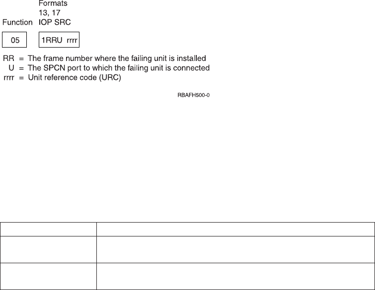
1. Power on the system.
2. Press the Increment (↑) or Decrement (↓) button on the control panel to display
Function 04.
Press Enter on the control panel.
3. Do all of the following lights on the system control panel go on?
vThe Processor Active/Activity light
vThe Processor Activity Select lights
vSystem Attention light
vPower On light
vA 5 x 7 dot pattern for each character in the Function/Data display
vMode lights (if available)
Yes No
↓Exchange the control panel or the replaceable unit that contains the
SPCN function (SPNLCRD or ac module). (See “Removal and
Installation Procedures”in the Problem Analysis information for your
system.)
4. The lights on the system control panel are working correctly.
This ends the procedure.
Function 05–SPCN SRC: Function 05 is available only on systems with SPCN.
Function 05 displays information about power faults and provides informational
reference codes during disk unit concurrent maintenance procedures. The format
for this function is as follows:
Function 06–Disable Continuous Power Main Storage (CPM): Function 06 is
available only on systems with SPCN. It is enabled only when you select Manual
mode and the system has enabled CPM.
When you power off the system, use this function to disable the continuous
powered main storage (CPM) operation.
Table 23. Function 06 Disable CPM
Function / value Action or description
06______ Use the Increment or Decrement buttons to scroll to function 06. If
you cannot scroll to function 06, CPM is not active.
06___E__ Press Enter to enter Disable CPM operation. E (Enable) indicates
that the CPM function is active.
Figure 75. SPCN SRC Formats
166 Service Functions V5R2

Table 23. Function 06 Disable CPM (continued)
Function / value Action or description
06___D__ Use the Increment or Decrement buttons to display option D
(Disable).
06____00 Press Enter to perform the Disable CPM operation. With the 00
displayed the operation was successful (the SPCN interface is
operational and the Disable message will be sent). At the next IPL,
CPM is automatically available. If FF appears instead of 00,
function 06 failed due to an SPCN communications error.
Function 07–Restore System Power and Perform Concurrent Maintenance
Repair: Function 07 is available only on systems with SPCN and only when the
system is powered on and in Manual mode. Function 07 allows you to restore
power to frames that had a power failure or were powered off. It is also used for
concurrent maintenance repair on bulks and fans.
When you first enter function 07, the control panel enters subfunction mode by
displaying (**). Increment and decrement functions scroll to selectable values. If an
SPCN communications error is present when you select a subfunction, the
subfunction does not start, and FF (processing failed) displays in the rightmost
display positions. Entry of a valid subfunction when no SPCN communications
errors are present results in a 00 (processing successful) displayed in the rightmost
display positions. Pressing Enter when ** is displayed results in exiting
subfunction mode. For example:
Table 24. Function 07 Restore System Power and Perform Concurrent Maintenance Repair
Function / data Action or description
07______ Use the Increment or Decrement buttons to scroll to function 07.
07**____ Press Enter to enter function 07 subfunction mode.
0704____ Use the Increment or Decrement buttons and scroll to desired
subfunction (04 in this example). Valid subfunctions are 01, 02, 03,
04, and 05.
0704__00
briefly, then
07**____
Press Enter to execute subfunction 04. An SPCN communications
error was not present, resulting in 00. If an error occurs, FF
displays.
07F3__00 Use the Increment or Decrement buttons to select a specific device
(in this case F0 - F3).
0704__00
briefly, then
07**____
Press Enter to exit the subfunction for the specified device and exit
to the subfunction level.
See the following list for valid subfunction values and their meanings.
** Cancel Request
The system returns this subfunction when you select ** for subfunction and
activate enter. Use this to cancel a pending subfunction 2–5 concurrent
maintenance operation. SPCN responds with an EPF 1–5 (enable panel
subfunction) to clear any other subfunction range enabled previously.
01 System Power On
Chapter 5. Control Panel Functions 167
If the processing unit is powered on, this command causes the system to
transmit a Rack Power On command to the network. After youcomplete
concurrent repairs, use this function to restore power to expansion units
that are turned off or faulted off.
02 Fan Power Off
Use this function to select a concurrent fan power off operation. SPCN
responds by enabling subfunction range F0–F3 (see “F0-F3 Select Fan”)to
select the fan to be powered off.
03 Bulk Power Off
Use this function to select a concurrent bulk power off operation. SPCN
responds by enabling subfunction range B0–B5 (see “B0-B5 Select Bulk”)to
select the bulk to be powered off.
04 Fan Power On
Use this function to select a concurrent fan power on operation. SPCN
responds by enabling subfunction range F0–F3 (see “F0-F3 Select Fan”)to
select the fan to be powered on.
You only need this function if the wrong fan is powered off. The system
automatically starts a concurrently repaired fan after the fan is inserted.
05 Bulk Power On
Use this function to select a concurrent bulk power on operation. SPCN
responds by enabling subfunction range B0–B5 (see “B0-B5 Select Bulk”)to
select the bulk to be powered on.
You only need this function if the wrong bulk is powered off. The system
automatically starts a concurrently repaired bulk after the bulk is installed.
F0–F3 Select Fan
Use this subfunction to select the fan for the previously selected concurrent
repair operation. If accepted, SPCN performs the operation and disables
this subfunction range. The system displays a function 5 SRC when the fan
is turned off and removes it when the fan is installed.
B0–B5 Select Bulk
Use this subfunction to select the bulk for the previously selected
concurrent repair operation. If accepted, SPCN performs the operation and
disables this subfunction range. A function 5 SRC is displayed when the
bulk is turned off and removed when the bulk is installed.
Function 08–Fast Power Off: Function 08 is enabled only when you select Manual
mode.
Use this function when the system is suspended and you cannot perform a power
down.
Initially, the system displays an attention SRC, 11-x A1xx 8008. This SRC indicates
that you selected Function 08. To perform a fast power off, see “Powering Off and
Powering On the System”in the Problem Analysis information for your system.
Note: If the system password was changed at the most recent IPL, performing a
fast power off might cause that new password information to be lost.
168 Service Functions V5R2
Functions 09 to 10–Reserved: These functions are reserved for future control
panel operations.
Functions 11 to 19–System Reference Code: Functions 11 though 19, if enabled,
represent the words of the SRC.
You should record SRC information for error reporting.
For more information on interpreting SRCs, go to Chapter 6, “System Reference
Code (SRC) Information”on page 191.
To use the SRC for problem analysis, go to the “Starting Point for All Problems”in
the Problem Analysis information for your system.
Function 20–System Type, Model, and Feature Code: This function displays the
machine type, model, and processor feature code in the following format:
tmmm cccc
Values for t indicate the machine type:
19401
29402
49404
69406
Values for m indicate the model:
mmm Model number (for example, 510)
Values for c indicate the system processor feature code:
cccc Processor feature code (for example, 2141)
You should record this information with the SRC.
Note: When the machine type and model number are not available, FF is shown.
Extended control panel functions (Models 150, 170, 250, 4xx,
50x, 51x, 530, 53S, 6xx, 7xx, SB1, and Sxx)
The extended control panel functions consist of two major groups:
vFunctions 21 through 49, which are available when you select Manual mode.
vSupport service representative Functions 50 through 99, which are available
when you select Manual mode, then select and enter the customer service switch
1 (Function 25), followed by service switch 2 (Function 26).
Note: When a function has no data to display, FF is shown.
Customer Extended Panel Functions (Models 150, 170, 250, 4xx, 50x, 51x, 530, 53S,
6xx, 7xx, SB1, and Sxx)
Function 21–Make DST Available: This function makes DST available on the
system console display. The Use Dedicated Service Tools (DST) display appears on
the primary or alternative console. For more information on the console, see
Determining a primary or alternative console.
Chapter 5. Control Panel Functions 169
To exit DST and return to the operating system, select the Resume operating system
display option on the Use Dedicated Service Tools (DST) display.
For more information, see Chapter 1, “Dedicated Service Tools (DST)”on page 1.
Function 22–Dump Main Storage: This function dumps main storage and
processor data to the disk.
Note: Prior to pressing function 22, check to see whether function 34 is available
(00 shows in the panel after you select function 34). If it is available, then
the system is attempting to run a main storage dump IPL. Using function 34
attempts to retry the IPL such that the original dump is not lost. If function
34 is not enabled (>FF shows in the panel after you select function 34), go
back and start function 22.
The first time that you select function 22 and press Enter, the system displays
attention SRC 11 A1xx 3022. This indicates that you selected function 22. To dump
main storage and system processor data to the disk, you must select function 22
again and press Enter. See “Performing a main storage dump to disk (manual
MSD)”on page 271.
Use this function only when a main storage dump is necessary, for example, a
suspended (system hang) condition or after an operating system failure.
Attention: No system shutdown is performed before the main storage dump. The
use of this function can cause loss of data. See “Function 34–Retry MSD IPL”on
page 186.
Functions 25 and 26–Service Switches 1 and 2: In function 25, the service
representative switch 1 is set. Function 25 is the first step necessary to set the
service function range (50 to 99).
In function 26, the service representative switch 2 is set. Function 26 is the second
step necessary to set the service function range (50 to 99).
Function 33–Reorder SPCN Addressing: This function puts the rack addresses in
the correct order to show their position in the System Power Control Network
(SPCN). Use it when you have added racks to or removed them from the system.
Function 34–Retry MSD or CPM IPL: Function 34 is enabled only for main
storage dump IPLs or CPM IPLs. You can use it when the system is hung during
the MSD IPL or CPM IPL to retry the IPL without losing the original dump
information.
Prior to pressing function 22, check to see whether function 34 is available (00
shows in the panel after you select function 34). If it is available, then the system is
attempting to run a main storage dump or power failure recovery (CPM) IPL.
Using function 34 attempts to retry the IPL such that the original dump is not lost.
If function 34 is not enabled (>FF shows in the panel after you select function 34),
go back and start function 22. See “Function 22–Dump Main Storage”.
Service Extended Panel Functions (Models 150, 170, 250, 4xx, 50x, 51x, 530, 53S,
6xx, 7xx, SB1, and Sxx)
170 Service Functions V5R2

Service functions 50 through 99 are enabled when you select Manual mode and
enter function 25 (service switch 1), then function 26 (service switch 2).
Subfunctions are used with Functions 51 and 54 through 64.
You can disable the service functions by selecting and entering either function 25
(service switch 1) or function 26 (service switch 2).
Using Subfunctions: After you select and enter the function (51, or 54 through 64),
the subfunction field appears with two asterisks (**). You can now select and enter
a subfunction value. When you have selected and entered a value, actual data, YY
FF (where YY is the function number), is displayed. The ’YY FF’response indicates
that no data is present for this subfunction value. The data displays as 8
hexadecimal digits (4 bytes of data).
You can repeat these steps for different subfunction values. To exit subfunctions,
select and enter the two asterisks for the subfunction value. Table 25 shows an
example of a subfunction data display.
Table 25. Subfunction Data Display Example
Function Subfunction Data Display
51 ** Subfunction mode entered
51 00, 01 NIA (8 bytes)
51 02, 03 Current TDE (8 bytes)
Function 50–System Processor Stop: This function stops the system processor.
Attention: This function might cause the system to end abnormally. Use only when
directed by your next level of support.
Function 51–System Processor Status: This function displays the following
values:
vNext instruction address (NIA)
vCurrent task dispatching element (TDE) address
The data can be displayed 8 digits at a time. Select and enter a subfunction
number to display each word of data from 00 to 0F.
Function 52–System Processor Start: This function starts the system processor
(after it has stopped).
Function 53–Path Switch: This function resets communication between the service
processor and the control panel.
Attention: Use this function only with proper supervision from your next level of
support.
Low-Level Debug (LLD) panel functions (Models 150, 170, 250,
4xx, 50x, 51x, 530, 53S, 6xx, 7xx, SB1, and Sxx)
You can enable these functions by selecting Manual mode, stopping the system,
and selecting Functions 25 and 26. Use these functions to analyze IPL errors. The
following is a list of all the low level debug (LLD) panel functions and a
description of each.
Function 54–Display I/O Configuration Table (ICT): The I/O configuration table
(ICT) contains the state of every I/O bus unit (IOBU) and bus extension unit that
Chapter 5. Control Panel Functions 171
is found on system bus 1. Using this function helps determine the status of the
load source IOP at the time of failure. To view data, display one word (4 bytes or 8
digits) at a time by selecting and entering a subfunction number from 00 to 3F.
See “Low-level debug and data collecting procedures”on page 131 for more
information.
Function 55–Display Service Processor Log Buffer (SPLB): The SPLB contains
data that is related to the system’s stopping. You can display the data 8 digits at a
time. Select and enter a subfunction number to display each word of data from 00
to FF.
See “Low-level debug and data collecting procedures”on page 131 for more
information.
Function 56–Display Service Processor Code Area (SPCA): The service processor
code area (SPCA) contains the state of the system processor and service processor
at the time of failure. This area contains data such as the failing load identifier
(LID), which indicates what LID the service processor wanted from the load-source
IOP. The data can be displayed 8 digits at a time. Select and enter a subfunction
number to display each word of data from 00 to FF.
See “Low-level debug and data collecting procedures”on page 131 for more
information.
Function 57–Display IPL Message Area (IMSA): The IPL Message Save Area
(IMSA) is a first-in-first-out queue of messages that were sent to the service
processor before the time of failure. This area is useful in determining the sequence
of events on the system I/O bus before the failure. The data can be displayed 8
digits at a time. Select and enter a subfunction number to display each word of
data from 00 to 3F.
See “Low-level debug and data collecting procedures”on page 131 for more
information.
Function 58–Display IPL Parameter Area (IPARMS): The IPL parameters area
contains the status of the type of IPL that you are performing. The data can be
displayed 8 digits at a time. Select and enter a subfunction number to display each
word of data from 00 to 08.
See “Low-level debug and data collecting procedures”on page 131 for more
information.
Function 59–Setting First and Second Characters of Address for MFIOP Control
Storage Display: See “Low-level debug and data collecting procedures”on
page 131 for more information.
Function 60–Setting Third Character of Address for MFIOP Control Storage
Display: See “Low-level debug and data collecting procedures”on page 131 for
more information.
Function 61–Setting Fourth Character of Address for MFIOP Control Storage
Display: See “Low-level debug and data collecting procedures”on page 131 for
more information.
Function 62–MFIOP Control Storage Display: See “Low-level debug and data
collecting procedures”on page 131 for more information.
172 Service Functions V5R2
Function 63–System Status SRC Trace: The system status SRC trace is a copy of
the last 25 status SRCs (those that are usually associated with the IPL sequence or
the power-off sequence).
Enter a subfunction between hexadecimal 00 and 18 to look at the status SRCs in
sequential order. The most recent SRC (the last status SRC) appears at subfunction
hexadecimal 18.
See “Low-level debug and data collecting procedures”on page 131 for more
information.
Function 64–Diagnostic Status SRC Trace: The diagnostic status SRC trace is a
copy of the last 25 status SRCs (those that are usually associated with the service
processor function of problem analysis and main store dump).
Enter a subfunction between hexadecimal 00 and 18 to look at the status SRCs in
sequence. You can see the most recent SRC (the last status SRC) at subfunction
hexadecimal 18 and the extended SRC words for this SRC at subfunctions 19
through 1A.
See “Low-level debug and data collecting procedures”on page 131 for more
information.
Function 65–Deactivate Remote Service: Function 65 is available only when you
have previously selected Manual mode and extended panel functions 25 and 26.
Use this function to deactivate a remote service session or iSeries Operations
Console. This function releases the communications port that was in use for a
remote service session or iSeries Operations Console.
Function 66–Activate Remote Service: Function 66 is available only when you
have previously selected Manual mode and extended panel functions 25 and 26.
Use this function to activate a remote service session or iSeries Operations Console.
This function activates the communications port that is used by remote service or
iSeries Operations Console.
Function 67–Disk Unit IOP Reset/Reload: Function 67 is not available for all
system types.
This function is used to initiate an IOP dump and a disk unit IOP reset/reload.
The function is enabled only when specific SRCs are displayed on the control panel
and the associated IOP supports a reset/reload function.
Function 68–Power off Disk Unit IOP/IOA Power Domain: Function 68 is
enabled only by specific disk unit system reference codes (SRCs) such as disk-unit
attention SRCs.
Function 69–Power on Disk Unit IOP/IOA Power Domain: Function 69 is
enabled when the power domain is powered off.
Function 70–MFIOP Control Storage Dump: This function dumps the contents of
the control storage from the MFIOP to segment identifier (SID) 0000000087 000000
(SID 87) on the load-source disk.
Chapter 5. Control Panel Functions 173

Control panel functions (Models 270, 8xx, SB2, SB3, and 890)
The control panel functions and descriptions are listed in Table 16 on page 160. For
more details about the functions, begin at “Control panel function descriptions
(Models 270, 8xx, SB2, SB3, and 890)”on page 177.
Notes:
1. Some control panel functions might not be available on all system types.
2. The xcan be any number 0 through 9, any letter A through F, or a blank.
3. If the customer was performing the function, find out why the customer
selected the function and verify whether it is complete.
4. If you cannot change the Function/Data display or complete the selected
function, go to “Starting Point for All Problems”in the Problem Analysis
information for your system.
Table 26. Control panel (32-character) function codes
Function code Function selected
01 1. Display the currently selected IPL type (and logical key mode on some system
types).
2. Display the currently selected IPL speed override for the next IPL.
02 Used to select the IPL type, logical key mode, and IPL speed.
03 Start an IPL to load the system. The IPL uses the selected IPL options.
04 Lamp test; all displays and indicators will be switched on.
05 System Power Control Network (SPCN) system reference code (SRC); displays an
SRC on the control panel.
07 Allows you to perform SPCN service functions.
08 Fast power off; to perform a fast power off, see “Powering Off and Powering On
the System”in the Problem Analysis information for your system.
09 through 10 Reserved.
11 through 19 System reference code (SRC); displays an SRC on the control panel.
20 Display the machine type, model, processor feature code, processor class indicator,
and IPL path description.
21 Causes the Use Dedicated Service Tool (DST) display to appear on the system
console; to exit DST, select the Resume operating system display option.
22 Force system main storage dump. First see “Function 34–Retry MSD IPL”on
page 186. To perform a system main storage dump, see “Performing a main
storage dump to disk (manual MSD)”on page 271.
23 Reserved.
24 Reserved.
25 Use Service switches 1 and 2 to enable or disable functions 50 through 99.
26 Use Service switches 1 and 2 to enable or disable functions 50 through 99.
27 through 32 Reserved.
33 Reorder SPCN addressing.
34 Retry MSD IPL.
35 through 49 Reserved.
50 System processing unit stop.
174 Service Functions V5R2
|
|
||
|
|
|
|
||
||
||
||
|
||
||
|
||
||
||
|
||
|
||
|
|
||
||
||
||
||
||
||
||
||

Table 26. Control panel (32-character) function codes (continued)
Function code Function selected
51 System processing unit status; displays the following values: B0 register contents,
Next Instruction Address (NIA), and current Task Dispatching Element (TDE)
contents
52 System processing unit start.
53 Activates, deactivates, and queries the Repeat GARD function.
54 Reserved.
55 Main store dump override processing
56 Reserved.
57 Display service processor diagnostic data area addresses.
58 Set the first character of the base address for the function 62 display.
59 Set the second character of the base address for the function 62 display.
60 Set third character of base address for function 62 display.
61 Set fourth character of base address for function 62 display.
62 Display service processor storage.
63 System status SRC trace.
64 Service processor diagnostic status SRC trace.
65 Deactivate remote service.
66 Activate remote service.
67 Disk unit IOP reset/reload; enabled only by specific disk unit SRCs.
68 Concurrent Maintenance power domain Power Off.
69 Concurrent Maintenance power domain Power On.
70 Dump service processor control storage.
71–99 Reserved.
If you cannot find the function code in this chart, the customer support for added features or devices might not
have been available when this information was produced. Look for any supplemental unit function code
information for the function code you displayed on the control panel. If you do not find any additional function
code information, go to “Function 04–Lamp Test”on page 181 and verify that the lamps are working correctly.
Ways to access the control panel (Models 270, 8xx, SB2, SB3,
and 890)
A keystick gives the operator security control over the control panel functions and
control over data that is accessible from the control panel. The keystick for the
electronic keylock activates the Mode-selection button.
Figure 76 on page 176 and Figure 77 on page 176 show the types of iSeries control
panels:
Chapter 5. Control Panel Functions 175
|
||
||
|
|
||
||
||
||
||
||
||
||
||
||
||
||
||
||
||
||
||
||
||
||
|
|
|
|
|
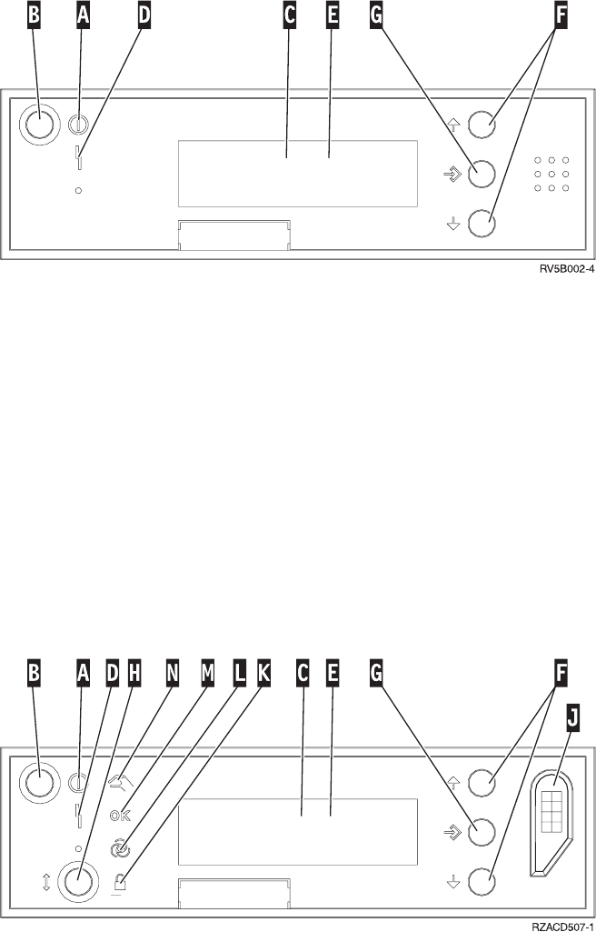
A Power On Light
vA blinking light indicates power to the unit.
vA constant light indicates that the unit is up and is working.
B Power Push button
C Processor Activity
D System Attention
E Function/Data Display
F Increment and Decrement buttons
G Enter Push button
A Power On Light
vA blinking light indicates power to the unit.
vA constant light indicates that the unit is up and is working.
B Power Push button
C Processor Activity
D System Attention
E Function/Data Display
Figure 76. iSeries control panel without a keystick
Figure 77. iSeries control panel with a keystick
176 Service Functions V5R2
F Increment and Decrement buttons
G Enter Push button
H Mode Selects
J Electronic Keystick Slot
K Secure
L Auto
M Normal
N Manual
If your control panel looks like Figure 77 on page 176, before you can use F
Increment and Decrement buttons and theG Enter push button, you need to press
H Mode Selects to select Manual mode N.
To determine how to activate functions 01 and 02 on a control panel, do the
following:
1. Does the control panel have an electronic keylock (a keystick)?
Yes No
↓The IPL key mode (M or N only) is displayed. The IPL key modes,
Auto and Secure, are not supported. Follow function 01 and 02
procedures for system types that do not use a keystick.
2. Insert the keystick.
Press the Mode-selection button to select the IPL mode. Follow function 01 and
02 procedures for systems with an electronic keystick.
To select a function number, press the Increment (↑) or Decrement (↓) button on the
control panel. To activate the function, press Enter on the control panel while the
desired function number is displayed.
Note: The function that is displayed is not activated until you press Enter on the
control panel.
Control panel function descriptions (Models 270, 8xx, SB2,
SB3, and 890)
Customer control panel functions (Models 270, 8xx, SB2, SB3,
and 890)
Function 01–Display Selected IPL Type and IPL Speed (on Systems with a
Keystick): This function allows you to display the selected type and speed for the
next IPL.
1. Display IPL types (A, B, C, or D).
2. Display IPL speed (F, S, SE, V=F, or V=S).
When selected, function 01 displays the currently selected IPL type and IPL speed
values (where each (_) represents 1 character):
Chapter 5. Control Panel Functions 177

Table 27. Function 01 on systems with a keystick
Function/data Action or description
01______________
________________
Use the Increment or Decrement buttons to
scroll to function 01.
01__A_____V=F___
________________
Valid IPL types are A, B, C, and D.
Valid IPL speed displays are F, S, SE, V=F,
or V=S.
01______________
________________
Use the Increment or Decrement buttons to
scroll through the control panel functions.
Function 01–Display Selected IPL Type, Logical Key Mode, and IPL Speed (on
Systems without a Keystick): This function allows you to display the selected
IPL type, logical key mode, and speed for the next IPL.
1. Display IPL types (A, B, C, or D).
2. Display the valid logical key modes (M or N).
3. Display IPL speed (F, S, SE, V=F, or V=S).
Table 28 shows a function 01 example on systems without a keystick.
Table 28. Function 01 on systems without a keystick
Function/data Action or description
01______________
________________
Use the Increment or Decrement buttons to
scroll to function 01.
01__A__M__V=F___
________________
Valid IPL types are A, B, C, and D.
Valid logical key modes are M and N.
Valid IPL speed displays are F, S, SE, V=F,
or V=S
01______________
________________
Use the Increment or Decrement buttons to
scroll through the control panel functions.
Function 02–Select IPL Type and IPL Speed Override (on Systems with a
Keystick): Before you can use function 02, you must have the system in Manual
mode. Selection changes to IPL types can be done with the system powered on or
off. Before you can select the IPL speed override, the system must be powered off.
Table 29 shows the sequence of selecting the IPL type on iSeries servers that are
powered on.
Table 29. Function 02 select IPL type on powered-on systems with a keystick
Function/data Action or description
02______________
________________
Use the Increment or Decrement buttons to
scroll to function 02.
02__A<__________
________________
Press Enter to start function 02. The current IPL
type is displayed with a pointer.
02__B<__________
________________
Use the Increment or Decrement buttons to
scroll through the IPL types.
178 Service Functions V5R2

Table 29. Function 02 select IPL type on powered-on systems with a keystick (continued)
Function/data Action or description
02______________
________________
Press Enter to select the IPL type and exit
function 02.
01______________
________________
Use the Increment or Decrement buttons to
scroll through the control panel functions.
Table 30 shows the sequence of selecting the IPL type and IPL speed on iSeries
servers that are powered off.
Table 30. Function 02 select IPL type and IPL speed on powered-off systems with a
keystick
Function/Data Action or Description
02______________
________________
Use Increment or Decrement buttons to scroll
to function 02.
02__A<______V___
________________
Press Enter to start function 02:
vThe current IPL type is displayed with
pointer.
vThe current IPL speed is displayed.
02__B<______V___
________________
Use the Increment or Decrement buttons to
scroll through the IPL types and speeds.
02__B_______V_<_
________________
Press Enter to select the IPL type.
vThe current IPL type is displayed.
vThe current IPL speed is displayed with a
pointer.
02__B_______S_<_
________________
Use the Increment or Decrement buttons to
scroll through the IPL speeds.
02______________
________________
Press Enter to select the IPL speed and exit
function 02.
01______________
________________
Use the Increment or Decrement buttons to
scroll through the control panel functions.
Function 02–Select IPL Type, IPL Speed Override, and Logical Key Mode (on
Systems without a Keystick): You can use function 02 in either Normal mode or
Manual mode. When the system is either powered on or off, this function allows
you to select the IPL type and logical key mode. Before you can select the IPL
speed override, the system must be powered off.
For powered-on systems without a keystick, function 02 is used to select the IPL
mode and logical key mode. Table 31 shows an example of the function 02 IPL
type and logical key mode selection sequence for a powered-on system that does
not have a keystick.
Table 31. Function 02 select IPL type and logical key mode on powered-on systems
without a keystick
Function/data Action or description
02______________
________________
Use the Increment or Decrement buttons to
scroll to function 02.
Chapter 5. Control Panel Functions 179

Table 31. Function 02 select IPL type and logical key mode on powered-on systems
without a keystick (continued)
Function/data Action or description
02__A<_M________
________________
Press Enter to start function 02.
vThe current IPL type is displayed with a
pointer.
vThe current logical key mode is displayed.
02__B<_M________
________________
Use the Increment or Decrement buttons to
scroll through the IPL types.
02__B__M<_______
________________
Press Enter to select the IPL type.
02__B__N<_______
________________
Use the Increment or Decrement buttons to
scroll through the logical key modes.
02______________
________________
Press Enter to select the logical key mode and
exit function 02.
01______________
________________
Use the Increment or Decrement buttons to
scroll through the control panel functions.
For powered-off systems without a keystick, function 02 is used to select the IPL
type, logical key mode, and IPL speed indicators. Table 32 shows an example of the
function 02 IPL type, logical key mode, and IPL speed selection sequence for a
powered-off system that does not have a keystick.
Table 32. Function 02 select IPL type, logical key mode, and IPL speed on powered-off
systems without a keystick
Function/data Action or description
02______________
________________
Use the Increment or Decrement buttons to
scroll to function 02.
02__A<_M____V___
________________
Press Enter to start function 02.
vThe current IPL type is displayed with a
pointer.
vThe current logical key mode is displayed.
vThe current IPL speed is displayed.
02__B<_M____V___
________________
Use the Increment or Decrement buttons to
scroll through the IPL types.
02__B__M<___V___
________________
Press Enter to select the IPL type.
vThe current IPL type is displayed.
vThe current logical key mode is displayed
with a pointer.
vThe current IPL speed is displayed.
02__B__N<___V___
________________
Use the Increment or Decrement buttons to
scroll through the logical key modes.
02__B__N____V_<_
________________
Press Enter to select the logical key mode.
vThe current IPL type is displayed.
vThe current logical key mode is displayed.
vThe current IPL speed is displayed with a
pointer.
180 Service Functions V5R2

Table 32. Function 02 select IPL type, logical key mode, and IPL speed on powered-off
systems without a keystick (continued)
Function/data Action or description
02__B__N____S_<_
________________
Use the Increment or Decrement buttons to
scroll through the IPL speeds.
02______________
________________
Press Enter to select the IPL speed and exit
function 02.
01______________
________________
Use the Increment or Decrement buttons to
scroll through the control panel functions.
Function 03–Start IPL: Function 03 is enabled only when the key mode is in
Manual and the system power is on.
This function starts an IPL of the selected IPL type when you press the Enter
button. All the Licensed Internal Code is loaded.
Attention: No system shutdown is performed before the IPL. The use of this
function can cause loss of data.
Function 04–Lamp Test: This function shows whether any control panel indicators
are burned out and whether characters that are displayed on the control panel
Function/Data display are valid. When you activate this test, all the control panel
lights and indicators flash on and off.
The lamp test continues on the system control panel until you perform another
control panel function or a power procedure. The expansion unit control panel
lamp test is active for 25 seconds and does not flash.
Use this procedure to verify that the lights on the system control panel are
working correctly. If you cannot complete these steps, go to the “Starting Point for
All Problems”in the Problem Analysis information for your system to start
problem analysis.
1. Power on the system.
2. Press the Increment (↑) or Decrement (↓) buttons on the control panel to display
Function 04.
Press Enter on the control panel.
3. Do all of the lights and indicators on the system control panel flash on and off?
Yes No
↓Exchange the control panel or the replaceable unit that contains the
control panel function [system unit backplane (MB1) or tower card
(CB1)]. See “Removal and Installation Procedures”in the Problem
Analysis information for your system.
4. Do the expansion unit control panel lights all come on?
Yes No
↓Exchange the control panel on the expansion unit.
The lights on the system control panel are working correctly.
This ends the procedure.
Chapter 5. Control Panel Functions 181

Function 05–SPCN SRC: Function 05 displays information about power faults
and provides informational reference codes during disk-unit concurrent
maintenance procedures. The format for this function is as follows:
Function 06: This function is reserved.
Function 07: Use this procedure to perform Function 07 operations by using the
system control panel in Manual mode.
To perform an SPCN operation that is controlled by function 07, do the following:
1. Select Function 07 and press Enter to display 07**.
2. Select the function that you want to perform (refer to Table 33). Use the
Increment or Decrement buttons (↑↓) to scroll to the appropriate function. Press
Enter to display 07nn 00, where nn is the function that you selected.
Table 33. SPCN functions in function 07
Function Action or description
A1 (Power On) Broadcasts a power-on command.
A2 (Turn Fan Off) Turns off a selected fan in a selected frame
(used only on the 840 Processor Tower).
A3 (Turn Power Supply Off) Turns off a selected power supply in a
selected frame (used only on the 840
Processor Tower).
A4 (Turn Fan On) Turns on a selected fan in a selected frame
(used only on the 840 Processor Tower).
A5 (Turn Power Supply On) Turn on a selected power supply in a
selected frame (used only on the 840
Processor Tower).
A6 (Display ID information) Displays ID information (type, serial
number, configuration ID) on the control
panel of the selected frame (see Figure 79 on
page 183). This function is available only for
secondary panels.
A7 (Power ON/OFF) Power a selected frame On or Off.
A8 (Query the SPCN Configuration ID) Display the SPCN configuration ID number
for a selected frame (see Figure 79 on
page 183). This function must be used for a
primary panel.
A9 (Set the SPCN Configuration ID) Set the SPCN configuration ID for a selected
frame.
AA Support-directed procedure only.
Figure 78. SPCN SRC formats
182 Service Functions V5R2
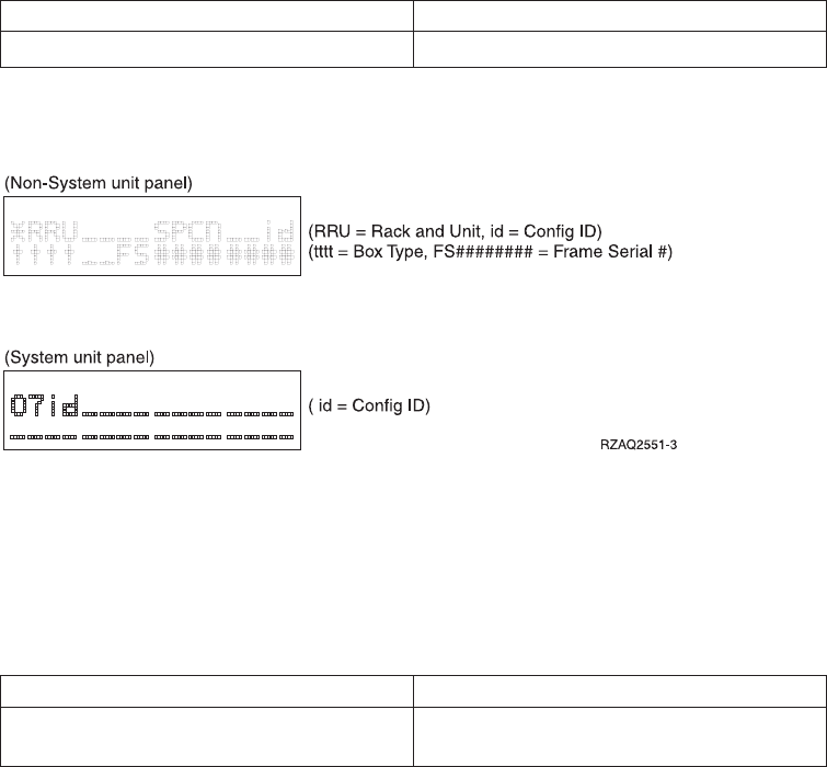
Table 33. SPCN functions in function 07 (continued)
AB Support-directed procedure only.
AC Support-directed procedure only.
Figure 79 shows the diagram for function A6 or A8 on a Non-System unit panel
and function A8 on a System unit panel..
3. Use the Increment (↑) or Decrement (↓) buttons to select the frame on which to
perform the function that you selected in step 2 on page 182. Press Enter.
4. If you selected function A2, A3, A4, or A5 in step 2 on page 182, select the
appropriate fan or power supply listed in the following table to perform the
operation on.
Fans Power supplies
00=B01, 01=B02, 02=B03, 03=B04 00=P01, 01=P02, 02=P03, 03=P04, 04=P05,
05=P06
5. If you selected function A6 or A8 in step 2 on page 182:
vIf a non-system unit address was selected in step 3, the non-system unit
display panel should be blinking and displaying data as shown in Figure 79.
vIf a system unit address was selected in step 3, use the Increment (↑)or
Decrement (↓) buttons to scroll to 07xx, where xx is the configuration ID.
The configuration IDs are defined as follows:
71 - xSeries Server Tower
80 - FC 5065/5066
81 - FC 5074/5079/8079
82 - FC 9079
83 - Model 830/SB2
84 - FC 5078/0578
89 - FC 5088/0588
8A - FC 5094/5294
8B - FC 5095
90 - FC 5075
91 - Model 270 CCIN 22A2, 22A4, 22A5, 2422 without FC 7104
92 - Model 270 CCIN 24A0, 24A2 without FC 7104
93 - Model 820 iSeries
95 - Model 270 CCIN 22A2, 22A4, 22A5, 2422 with FC 7104
96 - Model 270 CCIN 24A0, 24A2 with FC 7104
99 - FC 9094
6. If you selected function A7 in step 2 on page 182, select either C1 to power ON
the frame or C2 to power OFF the frame.
7. If you selected function A9 in step 2 on page 182:
Figure 79. Operations diagram for functions A6 and A8
Chapter 5. Control Panel Functions 183
vIf a non-system unit address was selected in step 3 on page 183, the
non-system unit panel should be blinking and displaying data as shown in
Figure 79 on page 183.
a. Use the Increment (↑) or Decrement (↓) buttons on the system unit control
panel to select the correct configuration ID from the table in step 5 on
page 183 (07nn should be displayed, where nn is the configuration ID).
b. Press Enter (07nn 00 should be displayed). After a few seconds, the
non-system unit display should stop blinking and return to displaying
the frame address.
vIf a system unit address was selected in step 3 on page 183:
a. Use the Increment (↑) or Decrement (↓) buttons on the system unit control
panel to select the correct configuration ID from the table in step 5 on
page 183. (07nn should be displayed, where nn is the configuration ID.)
b. Press Enter. On models 270 and 820, the control panel displays a series of
bring-up SRCs and then displays function 01. On a model 830 or FC 9079,
the control panel displays 07nn00.
8. When you have completed these steps, return to the normal panel display:
a. Scroll to 07** using the Increment or the Decrement buttons.
b. Press Enter.
This ends the procedure.
Function 08–Fast Power Off: Function 08 is enabled only when the key mode is
in Manual and the system power is on.
Use this function when the system is suspended and you cannot perform a power
down.
The first time that you select function 08 and press Enter, the system displays an
attention SRC, 11 A1xx 8008. This SRC indicates that you selected Function 08. The
second time that you select function 08 and press Enter, you confirm the request to
power off. To perform a fast power off, see “Powering Off and Powering On the
System”in the Problem Analysis information for your system.
Attention: No system shutdown is performed before the IPL. The use of this
function can cause loss of data.
Attention: If the system password was changed at the most recent IPL, performing
a fast power off might cause that new password information to be lost.
Functions 09 to 10–Reserved: These functions are reserved for future control
panel operations.
Functions 11 to 19–System Reference Code: Functions 11 though 19, if enabled,
represent the words of the SRC.
You should record SRC information for error reporting.
For more information on interpreting SRCs, go to Chapter 6, “System Reference
Code (SRC) Information”on page 191.
To use the SRC for problem analysis, go to the “Starting Point for All Problems”in
the Problem Analysis information for your system.
184 Service Functions V5R2
Function 20–System Type, Model, Feature Code, Hardware Level, and IPL Path
Description: This function displays the machine type, model, processor feature
code, hardware level, and IPL path description in the following format:
tmmmcccc________
hhhh____iiiiiiii
Values for t indicate the machine type:
19401
29402
49404
69406
Values for m indicate the model:
mmm Model number (for example, 820)
Values for c indicate the system processor feature code:
cccc Processor feature code (for example, 23A4)
Values for hhhh indicate the system processor hardware level:
hhhh Processor hardware level (for example, 1025)
Values for iiiiiiii indicate the description of the system power on or re-IPL path:
iiiiiiii IPL path description (for example, 00000001 indicates that the system was
powered on by using the white button on the control panel).
You should record this information with the SRC.
Extended control panel functions (Models 270, 8xx, SB2, SB3,
890)
The extended control panel functions consist of two major groups:
vFunctions 21 through 49, which are available when you select Manual mode.
vSupport service representative Functions 50 through 99, which are available
when you select Manual mode, then select and enter the customer service switch
1 (Function 25), followed by service switch 2 (Function 26).
Note: When a function has no data to display, FF is shown.
Customer Extended Panel Functions (Models 270, 8xx, SB2, SB3, 890)
Function 21–Make DST Available: This function makes DST available on the
system console display. The Use Dedicated Service Tools (DST) display appears on
the primary or alternative console. For more information on the console, see
“Determining a primary or alternative console”on page 128.
To exit DST and return to the operating system, select the Resume operating system
display option on the Use Dedicated Service Tools (DST) display.
For more information, see Chapter 1, “Dedicated Service Tools (DST)”on page 1.
Chapter 5. Control Panel Functions 185

Function 22–Dump Main Storage: This function dumps main storage and
processor data to the disk.
Note: Prior to pressing function 22, check to see whether function 34 is available
(00 shows in the panel after you select function 34). If it is available, then
the system is attempting to run a main storage dump IPL. Using function 34
attempts to retry the IPL such that the original dump is not lost. If function
34 is not enabled (>FF shows in the panel after you select function 34), go
back and start function 22.
The first time that you select function 22 and press Enter, the system displays
attention SRC 11 A1xx 3022. This indicates that you selected function 22. To dump
main storage and system processor data to the disk, you must select function 22
again and press Enter. See “Performing a main storage dump to disk (manual
MSD)”on page 271.
Use this function only when a main storage dump is necessary, for example, a
suspended (system hang) condition or after an operating system failure.
Attention: No system shutdown is performed before the main storage dump. The
use of this function can cause loss of data. See “Function 34–Retry MSD IPL”.
Functions 25 and 26–Service Switches 1 and 2: In function 25, the service
representative switch 1 is set. Function 25 is the first step necessary to set the
service function range (50 to 99).
In function 26, the service representative switch 2 is set. Function 26 is the second
step necessary to set the service function range (50 to 99).
Function 33–Reorder SPCN Addressing: This function puts the rack addresses in
the correct order to show their position in the System Power Control Network
(SPCN). Use it when you have added racks to or removed them from the system.
Function 34–Retry MSD IPL: Function 34 is enabled only for main storage dump
IPLs. You can use it when the system is hung during the MSD IPL to retry the IPL
without losing the original dump information.
Service Extended Panel Functions (Models 270, 8xx, SB2, SB3, 890)
Service functions 50 through 99 are enabled when you select Manual mode and
enter function 25 (service switch 1), then function 26 (service switch 2).
Subfunctions are used with Functions 51 and 57 through 64.
To enable functions 50 through 99:
1. Select function 25 and press Enter. The display reads 25 00.
2. Use the Increment button to select function 26 and press Enter. The display
reads 26 00.
Functions 50 through 99 are now available.
You can disable the service functions by selecting and entering either function 25
(service switch 1) or function 26 (service switch 2).
To disable functions 50 through 99, select function 25 and press Enter. Functions 50
through 99 are then no longer available.
186 Service Functions V5R2

Using Subfunctions: To work with subfunctions, do the following:
1. Use the Increment or Decrement buttons to select the appropriate function and
press Enter. The function number appears with asterisks (**); for example, 57**.
The two asterisks indicate that subfunctions are available.
2. Press the Increment button. The first subfunction number appears; for example,
5700.
3. As the subfunction number is displayed, press Enter. The data associated with
the subfunction number is displayed.
4. Press the Increment button. The next subfunction number appears; for example,
5701.
5. As the subfunction number is displayed, press Enter. The data associated with
the new subfunction number is displayed.
6. Repeat these steps to gather all the data that is associated with the subfunction.
7. Use the Increment or Decrement buttons to return to the function display with
asterisks; for example 57**.
8. Press Enter to exit the subfunctions.
Function 50–System Processor Stop: This function stops the system processor.
Attention: This function might cause the system to end abnormally. Use only when
directed by your next level of support.
Function 51–System Processor Status: This function displays the following
values:
vNext instruction address (NIA)
vCurrent task dispatching element (TDE) address
The data can be displayed 8 digits at a time. Select and enter a subfunction
number to display each word of data from 00 to 0F.
Table 34 is an example of a subfunction data display that shows NIA and TDE
information.
Table 34. Subfunction data display example
Function Subfunction Data Display
51 ** Subfunction mode entered
51 00, 01 NIA (8 bytes)
51 02, 03 Current TDE (8 bytes)
Function 52–System Processor Start: This function starts the system processor
(after it has stopped).
Function 53–Repeat GARD: The purpose of the Repeat GARD function is to
permanently de-configure an intermittently failing processor in case the IPL
diagnostics cannot detect the failure and de-configure it. Repeat GARD will
de-configure the failing processor during the IPL following the failure. The failing
processor must be replaced or the Repeat GARD function must be cleared before
that processor can be used again.
Attention: This function can cause a good processor to be permanently
de-configured following a power failure. Use only when directed by your next
level of support.
Chapter 5. Control Panel Functions 187
|
|
|
|
|
|
|
|
|
|

1. Select Function 53 and press Enter to display 53**.
2. Select the function you want to perform (refer to table below). Use the
Increment or Decrement button to scroll to the appropriate function. Press
Enter to display 53nn, where nn is the function that you selected.
Table 35. Repeat GARD Functions in Function 53
Function Action or Description
00 Clear memory, processor, L3 Repeat GARD
01 Enable memory, processor, L3 Repeat GARD
02 Disable memory, processor, L3 Repeat
GARD
03 View enable/disable status (E –enabled, D –
disabled)
Function 55–Override of Main Store Dump: The purpose of the main store
dump override function is to allow service representatives to modify the dump
policy implemented in the microcode. Once an override is set, it will stay in effect
until another override selection has been made.
1. Select Function 55 and press Enter to display 55**.
2. Select the function you want to perform (refer to the table below). Use the
Increment or Decrement button to scroll to the appropriate function. Press
Enter to display 55nn, where nn is the function that you selected.
Table 36. Override of Main Store Dump Functions in Function 55
Function Action or Description
00 View current setting
01 No override. Normal operation, where all
main store dumps requested will be taken.
02 No main store dump. No portion of the
dump will be taken and the system will
simply terminate with the failing SRC.
03 Complete hardware dump. Use only when
directed by your next level of support.
04 Base abbreviated hardware dump. Use only
when directed by your next level of support.
05 Checkstopped hardware dump. Use only
when directed by your next level of support.
06 Checkstopped with software registers
hardware dump. Use only when directed by
your next level of support.
Low-Level Debug (LLD) panel functions (Models 270, 8xx, SB2,
SB3, and 890)
You can enable these functions by selecting Manual mode and selecting Functions
25 and 26. The following is a list of all the low-level debug (LLD) panel functions
and a description of each.
Function 57–Display Service Processor Diagnostic Data Area Addresses: These
addresses can be used to display debug data in function 62.
188 Service Functions V5R2
|
|
|
|
|
|
||
||
||
||
|
||
|
|
|
|
|
|
|
|
|
|
|
||
||
||
|
||
|
|
||
|
||
|
||
|
||
|
|
See “Low-level debug and data collecting procedures”on page 131 for more
information.
Function 58–Setting First Character of the Base Address for the Function 62
Display: See “Low-level debug and data collecting procedures”on page 131 for
more information.
Function 59–Setting Second Character of the Base Address for the Function 62
Display: See “Low-level debug and data collecting procedures”on page 131 for
more information.
Function 60–Setting Third Character of Address for Function 62 Display: See
“Low-level debug and data collecting procedures”on page 131 for more
information.
Function 61–Setting Fourth Character of Address for Function 62 Display: See
“Low-level debug and data collecting procedures”on page 131 for more
information.
Function 62–Display Service Processor Storage: This function displays service
processor storage starting at the address that has been set with functions 58
through 61. See “Low-level debug and data collecting procedures”on page 131 for
more information.
Function 63–System Status SRC Trace: The system status SRC trace is a copy of
the last 25 status SRCs (those that are usually associated with the IPL sequence or
the power-off sequence).
Enter a subfunction between hexadecimal 00 and 18 to look at the status SRCs in
sequential order. The most recent SRC (the last status SRC) appears at subfunction
hexadecimal 18.
See “Low-level debug and data collecting procedures”on page 131 for more
information.
Function 64–Diagnostic Status SRC Trace: The diagnostic status SRC trace is a
copy of the last 25 status SRCs (those that are usually associated with the service
processor function of problem analysis and main store dump).
Enter a subfunction between hexadecimal 00 and 18 to look at the status SRCs in
sequence. You can see the most recent SRC (the last status SRC) at subfunction
hexadecimal 18 and the extended SRC words for this SRC at subfunctions 19
through 1A.
See “Low-level debug and data collecting procedures”on page 131 for more
information.
Function 65–Deactivate Remote Service: Function 65 is available only when you
have previously selected Manual mode and extended panel functions 25 and 26.
Use this function to deactivate a remote service session or iSeries Operations
Console. This function releases the communications port that was in use for a
remote service session or iSeries Operations Console.
Function 66–Activate Remote Service: Function 66 is available only when you
have previously selected Manual mode and extended panel functions 25 and 26.
Chapter 5. Control Panel Functions 189
Use this function to activate a remote service session or iSeries Operations Console.
This function activates the communications port that is used by remote service or
iSeries Operations Console.
Function 67–Disk Unit IOP Reset/Reload: Function 67 is not available for all
system types.
This function is used to initiate an IOP dump and a disk unit IOP reset/reload.
The function is enabled only when specific SRCs are displayed on the control panel
and the associated IOP supports a reset/reload function.
Function 68–Power off Disk Unit IOP/IOA Power Domain: Function 68 is
enabled only by specific disk-unit system reference codes (SRCs) such as disk-unit
attention SRCs.
Function 69–Power on Disk Unit IOP/IOA Power Domain: Function 69 is
enabled when the power domain is powered off.
Function 70–Dump Service Processor Control Storage: This function saves the
contents of the service processor control storage into nonvolatile storage for
potential use from an error log.
190 Service Functions V5R2

Chapter 6. System Reference Code (SRC) Information
Introduction ..............191
SRCformats..............191
Word1-SRCgeneralinformation.....193
Identifying SRCs ..........193
Word 2 - System status information .....194
Statusindicators..........194
System Reference Codes (SRCs) .......196
General system and Unit Reference Code (URC)
information.............196
System Reference Codes (SRCs) .....196
LIC Unit Reference Code Groups .....199
SPCN informational concurrent maintenance
SRCs ...............201
IPL status SRCs ...........201
General status SRCs ..........214
Introduction
The system reference code (SRC) is a sequence of data words (codes) that:
vIdentify a system status
vDescribe a detected hardware, Licensed Internal Code (LIC), or software failure
vDescribe the unit that is reporting the failure and its location.
SRCs can display on the control panel, appear in a system console message, appear
in the Primary partition’s console for secondary partitions, or appear in the
product activity log (see Chapter 3, “Product Activity Log”on page 99). For details
on how SRC information displays on the control panel, see “SRC formats”.
The system gathers information about an error as the system detects the error. The
Product Activity Log (PAL) logs and stores the error information. An SRC encodes
information used to evaluate or identify a system-detected hardware or software
error, failure, or status. The failure information may include the failing condition or
part (or unit) that can be exchanged or replaced and its location. The SRC links to
the problem determination procedure when the element detecting the failure
cannot isolate the failing condition. The SRC link completes the isolation process.
In summary, the SRC provides the first-failure-data-capture information. The
customer or support representative uses SRCs during problem determination,
repair actions, and verification. The SRC provides a link to the problem
determination procedures (hard or soft copy). Use the SRC and the problem
determination procedures to isolate the problem.
SRC formats
Models 150, 170, 250, 4xx, 50x, 51x, 530, 53S, 6xx, 7xx, SB1, S10, S20, S30, and S40
The control panel automatically displays the Function 11 word when it shows the
SRC (see “Word 1 - SRC general information”on page 193). You can select other
words (Functions 12 through 19) by using the control panel Increment (↑),
Decrement (↓), and Enter pushbuttons. Some portions of the SRC record might not
contain data. SRC records vary in length (up to 36 bytes) and display as described
in the following sections.
SRC records show with a -3 next to the function number in the Function/Data
display on all stage 3 hardware iSeries System Units (for example,
11-3 xxxx xxxx). The -3 indicates that the system uses stage three hardware. For
© Copyright IBM Corp. 1997, 2002 191

more information on stage three formats or hardware stages, see Appendix C of
iSeries Licensed Internal Code Diagnostic Aids - Volume 1.
The SRC record structure provides information about the machine at the time of
the failure.
For models 150, 170, 250, 4xx, 50x, 51x, 530, 53S, 6xx, 7xx, SB1, S10, S20, S30, and
S40, SRCs may consist of up to nine “data words”. A word (a word = 4 bytes of
sequential data) consists of 8 hexadecimal characters (0-9 or A-F). The function
number corresponds to the function on the control panel or Work with Partition
Status display that shows the specific word of the SRC. For these systems the word
number corresponds to the function number. For example, only word 1 (previously
called word 11 to match the function number) of the SRC appears in function 11.
See Table 37.
Models 270, 8xx, SB2, and SB3
Models 270, 8xx, SB2, and SB3 have a larger control panel than previous models.
They can display up to four words at a time. In addition, the first word of the SRC
can consist of ASCII or hexadecimal characters. The other eight words of the SRC
still consist of hexadecimal data. Function 11 still displays the first word of the
SRC, which can contain 8 to 32 characters (expanded word 1). In the Product
Activity Log (PAL) and other software displays, the SRC appears much like it does
for earlier releases, except for the possibility of word 1 containing up to 32
characters. Words display as a number from 1 to 9 instead of 11 to 19, thus
disassociating the word number from the function number. Refer to Chapter 3,
“Product Activity Log”on page 99 for more information on the PAL and SAL.
Refer to Table 37 to see the new format.
Example SRC record structure (all models)
Table 37. Example SRC record structure
Models 150, 170,
250, 4xx, 50x, 51x,
530, 53S, 6xx, 7xx,
SB1, S20, S30, and
S40
Models 270, 8xx, SB2,
and SB3
Function Function Characters Word Description
11 11 1–8 1 The leftmost 4 characters
displayed describe the reference
code identifier (usually the unit
reporting error). The rightmost 4
characters are the unit reference
code.
11 9–32 Extended
Word 1
12 12 1–8 2 Displays general system state
information.
13 12 9–16 3 Displays additional information
about the failure, such as
location of the unit, sense data,
and serial number.
Note: For some systems, Word
14 displays the unit address in
eight digits.
14 12 17–24 4
15 12 25–32 5
16 13 1–86
17 13 9–16 7
18 13 17–24 8
19 13 25–32 9
192 Service Functions V5R2

Notes:
1. Select Function 20 to display iSeries machine type, model number, and
processor feature code.
2. For Functions 14 through 19, data might not display for some SRCs.
Word 1 - SRC general information
Word 1 is the 8-digit SRC. The SRC includes a 2-byte unit reference code (URC)
and variable length configuration and supporting data. The URC is located in the
second half of Word 1 of the SRC. This SRC (including the URC) is used during
problem analysis. You can identify the type of SRC record by the first digit in
Word 1 using Table 38.
Identifying SRCs
The type of SRC can be identified by the first digit in the function 11 data display
as follows:
Function display Description
11 0xxx xxxx to 11 9xxx xxxx Hardware reported error.
11 Axxx xxxx Attention or action required. The system is waiting for a
user action. Example: This type of SRC is displayed on a
tape IPL if the tape unit is not ready.
11 Bxxx xxxx Machine check or internal error detected by Licensed
Internal Code. A Licensed Internal Code component
detected a system error. The problem could be failing
hardware or software. Follow the unit reference code tables.
11 Cxxx xxxx IPL status. Status SRCs are displayed to indicate the
progression of the IPL. These values can be:
vC1xx xxxx service processor
vC2xx xxxx secondary partition
vC3xx xxxx system processor
vC5xx xxxx LIC system hardware initialization
vC6xx xxxx Licensed Internal Code (LIC)
vC9xx xxxx OS/400 Operating System
vDxxx xxxx Diagnostic or power down status
11 Dxxx xxxx General system status. Status SRCs are displayed to indicate
the status of system functions when the console is not
available. Some of these functions are main storage dump or
delayed power off.
Note: x= any hexadecimal number
Table 38. General System Reference Codes (SRCs)
Problem SRC Description
Machine
problems
0xxx xxxx Problem reported by control panel
1xxx xxxx Problem reported by system power control network
2xxx xxxx through 9xxx xxxx Hardware machine check, usually IO related
B006 xxxx IOP common code
B1xx xxxx Service processor machine check
B143 xxxx Service Processor PAL entry
B2xx xxxx LPAR error conditions
B3xx xxxx –B4xx xxxx System processor hardware machine check
B6xx xxxx LIC machine check and LPAR configuration machine check
B8xx xxxx LIC resource management
Chapter 6. System Reference Code (SRC) Information 193

Table 38. General System Reference Codes (SRCs) (continued)
Problem SRC Description
B9xx xxxx Operating system machine check (See iSeries OS/400 Diagnostic
Aids)
Operator
intervention
A1xx xxxx Operation interruption by service processor
A6xx xxxx Operation intervention by LIC
A9xx xxxx Operation interruption by operating system
IPL status C1xx xxxx IPL status for the service processor
C2xx xxxx General status for normal LPAR power on
C3xx xxxx IPL status for the system processor
C5xx xxxx IPL status for system hardware initialization
C6xx xxxx IPL status for LIC
C6xx 4400 Automatic main storage dump recovery (IPL) status
C6xx 441x Automatic power failure recovery (IPL) status
C6xx 4500 through 4509 DST IPL status
C9xx xxxx IPL status for OS/400 operating system program. See iSeries
OS/400 Diagnostic Aids
General status D1xx xxxx General status for the service processor
D2xx xxxx General status for normal LPAR power off
D6xx xxxx General status for Main Storage Dump Manager, LIC run-time
status, or LIC power off
D9xx xxxx Power down status for OS/400 operating system program. See
iSeries OS/400 Diagnostic Aids
Word 2 - System status information
Word 2 provides a fixed location for information common to all SRCs shown on
the control panel. It is available for all SRC formats except power and control
panel. The service processor provides this information at the time the SRC is
displayed to the panel.
Notes for status indicators listed below:
1. For the coding of M, Main storage dump indicator, see “Main Storage Dump
Indicator (M)”.
2. For the coding of I, IPL state indicator, see “IPL State Indicator (I)”on page 195.
3. For the coding of G, IPL type last initiated indicator, see “IPL Type Last
Initiated Indicator (G)”on page 195.
Status indicators
Main Storage Dump Indicator (M): The first hexadecimal digit that is displayed
in Word 2 indicates whether the system started a main storage dump and if it was
successful. The indicator has the following meanings:
M Description
0Dump was not initiated
1Debug data exists, destructive data only
2Debug data exists, main storage only
3Debug data exists, main storage and destructive data only
4Debug data exists, partial dump (hardware data only)
5Debug data exists, hardware and destructive data only
194 Service Functions V5R2
6Debug data exists, full dump (main storage and hardware data)
7Debug data exists, extended dump (main storage, hardware data, and
destructive data)
8Debug data exists; dump failed after writing segment identifier (SID) 82 to
disk
9No debug data exists, destructive data access failed
ANo debug data exists, main storage dump failed
BNo debug data exists, destructive and main storage access failed
CNo debug data exists, partial dump failed
DNo debug data exists, hardware dump failed
ENo debug data exists, full dump failed
FNo debug data exists, extended dump failed
IPL State Indicator (I): The second digit that is displayed in Word 2 indicates
how far the IPL went on before the system displayed the SRC. The indicator has
the following meanings.
Hex Digit
IPL State Description
0Service processor IPL from start-up code in progress
1IPL from random access memory (RAM) is running
2Service processor task initialized
3LIC initialization completed
4Operational load of LIC is complete
5Bus manager initialized
6Main Storage initialization is complete
7Load Source DASD connection established
8Dedicated Service Tool (DST) or limited paging available
9Storage management directories verified
AAuthority structures verified
BIndexes verified
CDatabase verified
DLIC hand-off to operating system
EIPL is complete to sign on display
FPower down attempted
IPL Type Last Initiated Indicator (G): The third hexadecimal digit that Word 2
displays indicates the IPL type (IPL mode and environment) of the last IPL
performed, or the IPL running at the time of the failure. The IPL type for models
150, 170, 250, 4xx, 50x, 51x, 530, 53S, 6xx, 7xx, SB1, S20, S30, and S40 is coded as
shown in Table 39 on page 196. The IPL type for models 270, 8xx, SB2, SB3, and
890, is coded as shown in Table 40 on page 196.
Chapter 6. System Reference Code (SRC) Information 195

Table 39. IPL type indicator (models 150, 170, 250, 4xx, 50x, 51x, 530, 53S, 6xx, 7xx, SB1,
S20, S30, and S40)
IPL Type A IPL Type B IPL Type C IPL Type D
Power-on IPL A B C D
ProgrammedIPL1234
Function 3 IPL 5678
MSD IPL 9 E F N/A
Unknown IPL type
(Service Processor has
been reset)
0000
APower-on IPL (first row in the table) includes the IPL that occurs automatically
when someone turns on the main power switch or starts power after a power
failure. It also includes an IPL started by the timer and a remote IPL started by a
communication line.
AProgrammed IPL is an IPL that results from the PWRDWNSYS command with
Restart=Yes*FULL specified.
AFunction 3 IPL uses the selected IPL options to load the system. It is started by
selecting Function 03 on the control panel and pressing the Enter key.
Selecting IPL types A or B (type C is reserved) with Function 02 causes an IPL
from different areas on the load source DASD. IPL type D is from the alternative
load-source device, such as a tape or optical device.
Table 40. IPL Type Indicator (models 270, 8xx, SB2, SB3, and 890)
IPL Type A IPL Type B IPL Type C IPL Type D
Unknown IPL type
(Service Processor has
been reset)
0000
System Reference Codes (SRCs)
Notes:
1. For information about general status SRCs, see “General status SRCs”on
page 214.
2. For information about IPL status SRCs, see “IPL status SRCs”on page 201.
3. For detailed information about B6xx LIC SRCs, see iSeries Licensed Internal Code
Diagnostic Aids - Volume 1.
4. For detailed information about B9xx OS/400 SRCs, see iSeries OS/400 Diagnostic
Aids.
5. For information about other SRCs, see the Problem Analysis information for
your system model.
General system and Unit Reference Code (URC) information
System Reference Codes (SRCs)
Attention! This book does not list all SRCs. Start problem analysis with the
Problem Analysis information for your system model.
196 Service Functions V5R2

Table 38 on page 193 shows how SRCs are grouped. The SRC is a variable length
structure.
The SRCs are displayed as a sequence of words that may be displayed by selecting
different control panel functions. Function 11 is shown automatically when an SRC
is shown. You may select additional functions through function 20 by using the
Increment/Decrement (↑↓) switches and the Enter button. There is also an option
to include reference code details from the Work with Partition Status display. You
can also select SRC history option from the Display Partition Info menu.
The System Reference Code (SRC) Format Description: The format of the SRC
that you see depends on the system or server.
For more details about SRCs, refer to the following resources:
1. iSeries Information Center
2. iSeries Information Center,System Administration, Availability, and Maintenance
topic (for SRCs related to logical partitions)
3. Problem Analysis book for your system type (for service representatives)
4. iSeries Licensed Internal Code Diagnostic Aids - Volume 1, LY44-5900-05 (for service
representatives)
5. iSeries OS/400 Diagnostic Aids, LY44-5907-05 (for service representatives)
Hardware Related System Reference Code Formats: Use Table 41 to determine
the SRC format. See “SRC formats”on page 191 for other formats.
Table 41. Hardware-related SRC formats
Word IOP SRC Format 17 Data Device SRC Format 27
Data
IOP SRC Format 13 Data
1 TTTT RRRR tttt rrrr TTTT RRRR
2 MIGV EP17 MIGV EP27 MIGV EP13
3 BBBB Ccbb BBBB Ccbb BBBB Ccbb
4 @@@@ @@@@ @@@@ @@@@ @@@@ @@@@
5 TTTT LMMM tttt lmmm TTTT LMMM
6 tttt lmmm TTTT LMMM uuuu uuuu
7 ZZZZ rrrr ZZZZ RRRR uuuu uuuu
8 ssss ssss ssss ssss uuuu uuuu
9 uuuu uuuu uuuu uuuu uuuu uuuu
Function 20 Pxxx cccc Pxxx cccc Pxxx cccc
The symbols used in Table 41 are defined as follows:
@@@@ Unit address
BBBB Ccbb Bus, bus, card, and board address (direct select address)
lmmm Level indicator plus 3+digit model number of failing device
LMMM Level indicator plus 3+digit model number (for example, 6100 or
6150)
MMain storage dump indicator
rrrr Outboard failing unit reference code
Chapter 6. System Reference Code (SRC) Information 197

RRRR Unit reference code
ssss Serial number of failing unit
tttt Outboard failing unit type number (for example, 9337)
TTTT Type number or card identification number (hex 2xxx through
9FFF)
uuuu Unit specific data
VAdditional SRC information exists
ZZZZ Reserved
Pxxx Machine type and model, where P is the machine type and xxx is
the model:
vIf P=6, the type is 9406
vIf P=4, the type is 9404
vIf P=2, the type is 9402
MIGV EP General system status
For a description of the SRC, see Chapter 6, “System Reference Code (SRC)
Information”on page 191.
Logical Partition Work with Partition Status System Reference Code
Descriptions and Actions: The following B2pp xxxx (where pp=partition ID)
system reference codes only appear on the Work with Partitions Status display.
They appear only in the Primary partition, and describe error conditions
encountered during the IPL sequence of secondary partitions. Press F10 to monitor
SRCs. Press F9 to see additional SRCs. Under the Display Partition Information
display, there is an option to display SRC history of up to 200 SRCs and their
additional words for one or all partitions.
LIC Detected Problem Reference Code Formats:
Table 42. SRC formats when LIC detects a problem
Word LIC Format 60 Data LIC Format 61 Data LIC Format 62 Data
1 A6xx RRRR B6xx RRRR B6xx RRRR
2 MIGV EP60 MIGV EP61 MIGV EP62
3 CCCC 0000 cccc cccc cccc cccc
4 BBBB Ccbb pppp pppp pppp pppp
5 @@@@ @@@@ qqqq qqqq qqqq qqqq
6 TTTT mmmm qqqq qqqq qqqq qqqq
7 ssss ssss qqqq qqqq BBBB Ccbb
8 NNNN 0000 qqqq qqqq TTTT mmmm
9 0000 0000 qqqq qqqq 0000 0000
Table 42 represents the formats for Licensed Internal Code (LIC) SRCs.
vFormat 60 is used for LIC Attention SRCs.
vFormat 61 is used when LIC detects a LIC programming problem.
vFormat 62 is used when LIC detects an IOP Bus or IOP programming problem.
RRRR LIC unit reference code (URC).
198 Service Functions V5R2
cccc LIC Component Reference Code (CRC). Identifies the LIC component and
subcomponent that generated the SRC.
pppp LIC Program Reference Code (PRC). Identifies the LIC class or component
that generated the SRC and the specific error detected.
qqqq LIC Program Reference Code Qualifier. SRC words found at functions 15-3
through 19-3 or 15-3 and 16-3, depending on the format, provide additional
error isolation information that is specific to the Program Reference Code.
One or more of these words may be ‘0000 0000’.Format 61 has up to 5
words of PRC Qualifier, in words 5-9. The PRC determines the number of
PRC qualifer words. The content of words 5-9 is dependent on the value in
word 4. Format 62 has the PRC qualifier ONLY in words 5-6; there is
physical address and type information in words 7-9.
BBBB Ccbb
Bus/Card/Board identifiers of failing component (direct select address)
@@@@ Unit address
ssss Serial number of failing unit
TTTT Type number or card identification number of failing component (hex 2xxx
through 9FFF). May be 0000, if system data is not available at the time the
SRC is signaled.
ZZZZ Reserved
mmmm
Model number of failing component (hex 2xxx through 9FFF). May be 0000,
if system data is not available at the time the SRC is signaled.
CCCC Cause code
NNNN
Number of disk device facilities missing
MIGV EP
General system status (see Chapter 6, “System Reference Code (SRC)
Information”on page 191 for more information.)
xAny hexadecimal number
Notes:
1. For information about Function 11 and 12, refer to Chapter 6, “System
Reference Code (SRC) Information”on page 191.
2. Format 60 may contain data in a format other than that shown. Format 60 is an
old VLIC format, which some new LIC components use. It does not have the
component reference code and program reference code that format 61 and 62
have (61 and 62 were specifically defined for the new LIC). Format 60 is mostly
component-specific with no key information to indicate format (the developer
has to interpret it). Refer to the Problem Analysis information and perform the
problem isolation procedure used by the reference code to further define any
significant data.
LIC Unit Reference Code Groups
The four-digit unit reference codes follow. These codes are grouped by their first 2
or 4 digits. The groups are:
Group Number Description
00-01 Machine Check Handler
02 Storage Mgmt
Chapter 6. System Reference Code (SRC) Information 199
03 Exception Mgmt
04 IPL
05 Process Mgmt
06 Resource Mgmt
07 Modula–2 Support
08 LID Manager
09 Link Loader
0B Authority
10 Tasking / Queueing
11 Machine Facilities
12 Database
13 Journal
14 Reclaim
15 Translator
16 Source/Sink
17 Common Error Types
18 Power IPL status
19 MUTEX
20–27 Hardware-related errors
30 MSD from Hypervisor
40 IPL status
41 Install IPL status
42 Storage Mgmt IPL status
43 LinkLoader IPL & runtime status
440x Main store dump IPL status
441x Continuously Powered Main Storage IPL Status
45 DST IPL status
4A-4F Database IPL status
50 DST status
5120-5128 LIC Common machine check
52 I/O processor failure
53 Logical partition configuration
55 I/O DASD subsystem status
69 I/O hardware error
70-71 Communications
72 UPS Interface
74 JAVA Virtual Machine
200 Service Functions V5R2
77 I/O HRI
78 Private Address Space Environment
CE Remote DST
CF Optical I/O Subcomponent
F1 Hypervisor
FD LIC Error
Each reference code is divided into these sections:
vDescription
vService recovery action
vService problem analysis procedure
To determine the meaning and service action for the SRC, use the “Diagnostic
Aids”or the “Problem Analysis”document for the system model that has the
error.
A main storage dump is taken for most of the LIC URCs unless otherwise
indicated in the description of the URC.
SPCN informational concurrent maintenance SRCs
1xxx 01xx
Install hardware unit
1xxx 02xx
Remove hardware unit
1xxx 03xx
Hardware unit is installed
1xxx 04xx
Hardware unit is removed
1xxx 05xx
No action was detected; the bus was released
1xxx 07xx
No action was detected; regulator is turned off
1xxx 08xx
Blower turned off for concurrent maintenance
1xxx 09xx
Bulk turned off for concurrent maintenance
IPL status SRCs
As the system performs an IPL, SRCs appear on the control panel. The SRCs
indicate the status of the IPL and are often useful in problem analysis. The
following list provides information on the IPL process and shows some of the
SRCs (in numeric order) that can appear during an IPL.
IPL SRC
Function Performed
C1xx 1xxx
Service Processor ROS IPL in progress
Chapter 6. System Reference Code (SRC) Information 201
C1xx 1006
Service processor ROS loading RAM from MFIOP directed device
C1xx 1007
Service Processor ROS retrying attempt to load RAM from MFIOP directed
device
C1xx 1008
Service Processor ROS attempting to load RAM from non-MFIOP directed
device
C1xx 1009
Service Processor ROS retrying attempt to load RAM from non-MFIOP
directed device
C1xx 1016
Service Processor ROS attempting to load RAM from MFIOP default device
C1xx 1018
Service Processor ROS attempting to load RAM from non-MFIOP default
device
C1xx 1019
Service Processor ROS retrying attempt to load RAM from non-MFIOP
default device
C1xx 100C
Service processor ROS IPL complete, branch to RAM Loader
C1xx 1030
Loading Service Processor system LIC from MFIOP device
C1xx 1050
Loading Service Processor system LIC from non-MFIOP device
C1xx 2001
Service Processor is setting up to test and load system processor
C1xx 2002
Service processor is testing system processor and main storage
C1xx 2003
Service processor is loading system processor
C100 2034
LIC (system) has been initialized; control has passed to system processor
C1xx 2050
Service Processor is waiting for Load Source device
C1xx 2060
Service Processor started a read command from Load Source
C1xx 2090
Service Processor completed a read command from load source
C1xx 80xx
Service Processor/Control Panel communication in progress
C1xx 805x
Service Processor is loading Control Panel LIC
C1xx B1xx
Basic assurance test completed on MFIOP
202 Service Functions V5R2
C100 D009
LIC (system) running initialization
C200 1xxx
Secondary Partition Early IPL Initialization Phase
C200 1100
Adding partition resources to the secondary configuration
C200 11FF
Partition resources added successfully
C200 2xxx
Secondary Partition SPCN Tower Power ON Phase
C200 1200
Checking if IPL is allowed
C200 12FF
Partition IPL is allowed to proceed
C200 1300
Initializing ISL roadmap
C200 13FF
ISL roadmap initialized successfully
C200 1400
Initializing SP Communication Area #1
C200 1410
Initializing IPL parms
C200 14FF
IPL parms initialized successfully
C200 3xxx
Secondary Partition Bus Unit ISL Phase
C200 3100
Validating ISL command parameters
C200 3111
Waiting for Bus object to become operational
C200 3112
Waiting for bus unit to become disabled
C200 3150
Sending ISL command to bus unit
C200 31FF
Waiting for ISL command completion
C200 32FF
ISL Command complete successfully
C200 4xxx
Secondary Partition Load Source Device Connection Phase
C200 4100
Waiting for load source device to enlist
C200 4200
Load source device has enlisted
Chapter 6. System Reference Code (SRC) Information 203
C200 4300
Preparing connection to load source device
C200 43FF
Load source device is connected
C200 5xxx
Secondary Partition Main Storage Dump Phase
C200 5100
Preparing to initiate MSD phase
C200 5110
Loading SID 82 from load source device
C200 5115
MSD Phase I
C200 5120
Writing processor registers into SID 82
C200 5125
MSD Phase II
C200 5130
Writing mainstore pages to the load source device
C200 5135
MSD Phase III
C200 5140
Storing (final) SID 82 back to the load source device
C200 5150
Allocating the hardware page table
C200 51FF
MSD processing complete
C200 6xxx
Secondary Partition Load LIC From Load Source Phase
C200 6000
Locating First LID information on the loadsource
C200 6010
Locating Next LID information on the loadsource
C200 6020
Verifying LID information
C200 6030
Priming LP Configuration LID
C200 6040
Preparing to initiate LID load from loadsource
C200 6050
LP Configuration LID primed successfully
C200 6060
Waiting for LID load to complete
C200 6100
LID load completed successfully
204 Service Functions V5R2
C200 7xxx
Secondary Partition Load Source Device Disconnection Phase
C200 7100
Disconnecting from load source device
C200 7110
Preparing to remove the load source IOP from the primary partition
C200 7120
Load source IOP has been successfully removed from the primary partition
C200 71FF
Load source is successfully disconnected
C200 8xxx
Secondary Partition Start Processors Phase
C200 8100
Initializing SP Communication Area #2
C200 8104
Loading data structures into mainstore
C200 8110
Initializing event paths
C200 8120
Starting processors
C200 81FF
Processors started successfully, now waiting to receive the continue
acknowledgment from SLIC
C200 8200
Continue acknowledgment received from SLIC
C200 82FF
VSP IPL complete successfully
C3xx xxxx
System Processor or Main Storage Diagnostic in progress
C5xx xxxx
LIC system hardware initialization
C500 C92B
Waiting for console device - error condition only if console not found
C6xx 1800
LIC SPCN setup
C600 3900
SP transfer control of Bus 1 (BCU Switch) to LIC is Complete and LIC
Machine Facilities component is initialized
C600 3910
LIC has initiated PCI Bus Reset to all Bus 1 devices except the SP
C600 3911
LIC has initiated self test of all Bus 1 devices except the SP
C600 3912
LIC is initiating IPL of the Load Source IOP
Chapter 6. System Reference Code (SRC) Information 205
C600 3913
LIC is initializing the Load Source IOP messaging functions
C600 3914
LIC has detected a Load Source IOP problem and is resetting the IOP, or
the IOP has requested a reset after an internal Flash memory LIC update
C600 3915
LIC has initiated the Load Source IOP self-load
C600 3916
During self-load, the Load Source IOP signalled LIC that it is initiating an
internal Flash Memory update or other critical function
C600 3917
The Load Source IOP has completed IPL of its operational load, LIC is
waiting for the IOP to report its attached IO resources
C600 4001
Static paging
C600 4002
Start limited paging, call LID manager
C600 4003
Initialize IPL/Termination (IT) data area / set up node address
communication area (NACA) pointer
C600 4004
Check and update MSD SID
C600 4005
Initialize event management is running
C600 4006
IPL all busses
C600 4007
Start error log ID
C600 4008
Initialize I/O service
C600 4009
Initialize I/O machine
C600 4010
Initialize IDE (interactive device exerciser)
C600 4011
Initialize remote services
C600 4012
Initialize RMAC component data values
C600 4013
Initialize context management
C600 4014
Initialize RM (component) seize lock
C600 4015
Initialize MISR
C600 4016
Set time of day
206 Service Functions V5R2
C600 4017
Initialize RM (component) process management
C600 4018
Initialize error log
C600 4019
Restart the service processor
C600 4020
Initialize machine services
C600 4021
Initialize performance data collector
C600 4022
Initialize event management
C600 4023
Create MI boundary manager tasks
C600 4024
Disable CPM
C600 4025
Initializes battery test
C600 4026
Hardware card checkout
C600 4027
Start integrated device exerciser (Type C IPL only)
C600 4028
Start DST
C600 4029
Make IPL task not critical
C600 4030
Free static storage
C600 4031
Destroy IPL task
C600 4032
Initialize Integrated File System descriptor management
C600 4033
Initialize LPAR Virtual I/O
C600 4050
Storage management recovery is running
C600 4051
Start LOG is running
C600 4052
Trace table initialization is running
C600 4053
Context rebuild is running
C600 4054
Start product activity log and Advanced Peer-to-Peer Networking
®
(APPN)
is running
Chapter 6. System Reference Code (SRC) Information 207
C600 4055
Authority recovery is running
C600 4056
Journal recovery is running
C600 4057
Database recovery is running
C600 4058
Journal synchronization is running
C600 4059
Commit recovery is running
C600 4060
Database initialization is running
C600 4061
Journal IPL clean up is running
C600 4062
Commit initialization is running
C600 4064
System Object Model
™
(SOM) recovery is running
C600 4065
Start operating system is running
C600 4070
Integrated File System recovery is running
C600 4100
Searching for Load Source Candidate (D-mode only)
C600 4101
Opening media-file to install LIC service displays with proper National
Language Version
C600 4102
Loading and linking from media-file to install LIC service displays with
proper National Language Version
C600 4201
Storage management recovery
C600 4204
Synchronization of mirrored MSD
C6xx 4205
Synchronization of mirrored data (where xx is percent complete).
C600 4240
Reclaim main storage
C600 4250
Storage management subset directory recovery
C600 4255
Defragmentation utility
C600 4260
Storage management directory recovery
208 Service Functions V5R2
C600 4272
ASP overflow recovery
C600 4300
Static paging is available for the link loader
C600 4301
Applying temporary PTFs. If the IPL stops at this point, you might need to
install the Licensed Internal Code again.
C600 4302
Applying modules. If the IPL stops at this point, you might need to install
the Licensed Internal Code might again.
C600 4303
Temporarily applied PTFs have reached the static paging phase
C600 432A
Resolving references to run Mode A; you can safely stop the system while
it is doing this work.
C600 432B
Resolving references to run Mode B. You may safely stop the system while
it is doing this work.
C600 4330
Full paging is available; workstation HRI processing
C600 4331
Freeing unused nucleus pages
C600 4332
Permanently applying PTFs. If the IPL stops at this point, you may need to
install the Licensed Internal Code again.
The following SRCs can appear during an MSD IPL.
C6xx 4400
Unattended DASD checker started
C6xx 4401
Attended DASD checker started
C600 4402
Main storage dump manager and storage management recovery started
C600 4403
Storage management recovery ended
C6xx 4404
LIC log started (where xx is dump copy percent completed).
C600 4405
Dump auto copy completed. Shutdown or programmed IPL has started.
C600 4406
Shutdown or programmed IPL (MSD related) has started.
End of MSD IPL SRCs.
The following SRCs can appear during a CPM IPL.
C6xx 4410
Unattended DASD checker started
Chapter 6. System Reference Code (SRC) Information 209
C6xx 4411
Attended DASD checker started
C600 4412
Storage management recovery started
C600 4414
LIC log started
C600 4416
Shutdown or programmed (CPM-related) IPL has started
End of CPM IPL SRCs.
The following are DST SRCs for Attended IPLs.
C600 4500
Verifying network attributes
C600 4501
Looking for the console
C600 4502
Starting DST display task
C600 4503
Checking possible machine-readable information (MRI) on media
C600 4504
Verifying system serial number
C600 4505
Verifying system type
C600 4506
Verifying system-unique ID (OS/400 only)
C600 4507
Starting ’before DST’DASD checker
C600 4508
Verifying system password (if DASD check OK; if not OK this is checked
when IPLing past DST)
C600 4509
Starting DASD migration function (only if migrating)
C600 450A
Starting ’after DST’DASD checker (can happen twice)
The following are DST SRCs for Unattended IPLs.
C600 4500
Verifying network attributes
C600 4504
Verifying system serial number
C600 4505
Verifying system type
C600 4506
Verifying system-unique ID (OS/400 only)
210 Service Functions V5R2
C600 4508
Verifying system password (if DASD check OK)
C600 450A
Starting ’after DST’DASD checker
C600 450C
DST IPL status
End of DST SRCs for Unattended IPLs.
C600 4A57
Parallel database recovery is at Pass 1
C600 4A60
Parallel database initialization is at Pass 1
C600 4B57
Parallel database recovery is at Pass 2
C600 4B60
Parallel database initialization is at Pass 2
C600 4C57
Parallel database recovery is at Pass 3
C600 4C60
Parallel database initialization is at Pass 3
C600 4F57
The system is recovering all database objects. This step can take several
hours. It can occur any time when database recovery is in progress.
C600 4F60
The system is examining all objects during database initialization. It can
occur any time when database initialization is in progress.
Note: At this point LIC initialization is complete, and operating system starts. All
hardware is verified.
IPL SRC
Function Performed
If the system uses the OS/400 operating system, the following status SRCs appear:
C900 2810
Reclaim machine context
C900 2820
Resolve system objects
C900 2825
Convert Work Control Block Table
C900 2830
System value object
C900 28C0
Prepare SPCF job
C900 28C5
Initialize system objects
C900 2910
Start system logging
Chapter 6. System Reference Code (SRC) Information 211
C900 2920
Library and object information repository (OIR) cleanup
C900 2925
Verify POSIX** root directories
C900 2930
Database cross-reference
C900 2940
Console configuration
C900 2950
Install complex objects
C900 2960
Sign on processing
C900 2965
Software Management Services (SMS) initialization
C900 2967
Applying PTFs
C900 2968
IPL options
C900 2970
Database recovery part 1, journal recovery part 1
C900 2973
This recovery step attempts to perform any needed recovery for Database
files that were definitionally being changed, created or deleted when an
abnormal system end occurred.
C900 2976
This recovery step verifies the object recovery list performs any needed
recovery for Journals and Journal Receivers.
C900 2978
This IPL Status SRC is displayed when SRCs C900 2A70 - C900 2976 have
been completed
C900 2980
Storage requirements
C900 2990
Performance adjustments
C900 29A0
System control block
C900 29B0
Spool initialization
C900 29C0
Work control block table
C900 2A80
Before starting system jobs
C900 2A85
Bringing up POSIX SAG
C900 2A87
POSIX SAG restart and signals initialization
212 Service Functions V5R2
C900 2A90
Starting system jobs
C900 2A95
Abnormal Work Control Block Table cleanup
C900 2AA0
Damage Notification
C900 2AA1
This recovery step either rolls back or completes certain uncompleted
Database operations that were run under Commitment Control
C900 2AA2
This recovery completes certain Journal operations that were in progress
when the system ended processing
C900 2AA3
This recovery sends messages to QHST for Database files that may have
been damaged by a system end
C900 2AA3
This recovery sends messages to QHST for Database files that may have
been damaged by a system end
C900 2AA4
This IPL Status SRC is displayed when SRCs C900 2AA0 - C900 2AA3
have been completed
C900 2AA5
Integrated File System/New File System (NFS) directory recovery
C900 2AAC
Integrated File System conversion
C900 2AB0
Database Recovery part 2
C900 2AC0
Document Library Object (DLO) recovery
C900 2B10
Establish event monitors
C900 2B30
QLUS job
C900 2B40
Device configuration
C900 2C10
After system arbiter
C900 2C20
SNADS recovery
C900 2C25
ZMF component (Mail Enablement (OeDS) Framework) recovery
C900 2C40
Work Control Block Table cleanup
C900 2CF0
Reclaim storage
Chapter 6. System Reference Code (SRC) Information 213
C900 2F00
IPL Complete
Operating system initialization is complete when the sign-on screen displays on
the console.
General status SRCs
The following list contains general status SRCs listed in numerical order. The xx
that is used in the SRCs represents a hexadecimal number further defining the
code.
Status Function Performed
D100 8000
Service Processor (SP) is in the process of powering down.
D100 8025
Power down SPCN. This SRC appears during the system shutdown for
Continuously Powered Main Storage (CPM). When the system is in CPM,
the control panel is off, and the display is dark.
D1xx 3xxx
Service Processor portion of MSD in progress
D1xx 30xx
Preparing or writing to disk
D1xx 31xx
System is preparing segment ID 82 data area
D1xx 3200
Preparing or writing from main storage
D1xx 32xx
The last MSD status SRC. xx+1 is the number (in hexadecimal) of 16MB
blocks that are dumped from main storage.
D1xx 8000
Service Processor is in the process of powering down
D1xx 8025
Service Processor is in the process of powering down in CPM mode
D1xx 8030
Service Processor has received a Delayed Power Off request
D1xx 8035
Service Processor Delayed Power Off request has timed out. Main store
dump will follow.
D1xx 8065
Remote Service/Operations Console communications line
deactivated/failed to activate.
D1xx 8066
Remote Service/Operations Console communications line active.
D1xx D505
MFIOP Initialization in progress
D200 xxxx
Secondary Partition Power OFF Phase
214 Service Functions V5R2
D6xx 0298
System shutdown started
D6xx 0299
System shutdown status
D6xx 0483
Power failed; delay timer is running
D6xx 0484
MI run in progress
D6xx 5500
System shutdown status; attempting to delete information from the disk
subsystem cache
D6xx 5501
System shutdown status; indicates that the information from the disk
subsystem cache was deleted successfully
D6xx 5502
System shutdown status; indicates that the system failed to delete
information from the disk subsystem cache
D6xx 5503
System shutdown status, which indicates the information from the disk
subsystem cache was deleted with qualified success
D900 2740
Power down immediate
D900 2750
All subsystems ended
D900 2760
Device configuration shutdown
D900 2770
QLUS job ending
D900 2780
Close database cross-reference files
D900 2790
QSYSARB job ending
D900 27C0
System jobs are ending
Chapter 6. System Reference Code (SRC) Information 215
216 Service Functions V5R2

Chapter 7. Initial Program Load (IPL) Information
IPLtype,mode,andspeedoptions......217
IPLspeedrecommendations.......217
Methods to perform IPL..........217
Alternate installation IPL .........218
IPLsequence.............218
Service processor initialization.......218
Functions performed .........218
What is initialized ..........218
Abnormal ending ..........219
Licensed Internal Code (LIC) initialization. . . 219
Functions performed .........219
Abnormal ending ..........219
Initialization output .........220
Data descriptions ..........220
Log entries ............220
Status SRCs ..............221
IPL type, mode, and speed options
Set the IPL options from function 02 on the control panel. To permanently change
the IPL speed use the CHGIPLA command.
vUse function 01 to display the current IPL option, including IPL speed. This is
the option and speed that the system will use at the next IPL. Refer to “Function
01–Display Selected IPL Type and Speed (on Systems with a Keystick)”on
page 162 for more information about function 01.
vRefer to the information in Table 15 on page 159 for speed override definitions.
vUse the HDWDIAG (hardware diagnostics) parameter of the CHGIPLA command to
permanently change the IPL speed. The values are: The default shipped value
*MIN (minimal) for fast diagnostics and *ALL for all (full) diagnostics.
IPL speed recommendations
vUse CHGIPLA *MIN, or Function 02 For V=F for most IPLs (to perform a fast IPL
that uses minimum diagnostics).
vUse CHGIPLA *ALL, or Function 02 Sor V=S, if you change hardware or suspect an
intermittent hardware failure (to perform a slow IPL that uses all diagnostics).
vUse CHGIPLA *ALL, or Function 02 Sor V=S during the first Install IPL. You can
set this at the panel with Function 02; it affects only the one IPL because the
next IPL will again pick up the value set with CHGIPLA.
For more information about:
vIPL types, see Table 13 on page 159
vIPL modes, see Table 14 on page 159
vIPL speeds, see Table 15 on page 159
vControl panel functions, see “Control panel function descriptions (Models 150,
170, 250, 4xx, 50x, 51x, 530, 53S, 6xx, 7xx, SB1, and Sxx)”on page 162 or the
system operator information
Methods to perform IPL
Table 43. Methods to perform IPL
Methods Description
POR Power on reset IPL. The system was powered off and powered on. During the power on,
all hardware runs diagnostic tests.
© Copyright IBM Corp. 1997, 2002 217

Table 43. Methods to perform IPL (continued)
Methods Description
F03 Attention: No system shutdown is performed before the IPL. The use of this function can
cause loss of data.
Control panel Function 03 starts a Load IPL. This differs from a POR IPL because no power
off and power on sequence is done. This means a system shutdown is not performed and
not all hardware diagnostics are performed during the IPL. Input-output processors (IOP)
are reset using a software POR equivalent.
Programmed IPL
without parameters
This IPL is started by the operating system. A PWRDWNSYS command with RESTART
(*YES) will initiate this IPL.
Remote power on An unattended IPL is started from a remote location (using a modem). Normal mode must
be selected, the system power must be turned off, and the user must set specific indicators
(see the system operation information).
Automatic restart An unattended IPL is started automatically after a power failure. Normal mode must be
selected and the user must set specific indicators (see the system operation information).
Power on by
date/time
This IPL is started by an internal clock. Normal mode must be selected and the user must
set specific indicators (see the system operation information).
Alternate installation IPL
To enable an alternate installation IPL, select the dedicated service tool (DST)
option to Work with alternate installation device; see “Work with Dedicated Service
Tools environment”on page 23 or “Work with alternate installation device”on
page 27. This option is available in DST from control panel function 21 or a type D
IPL. For more information about defining and enabling the alternate installation
device, see Software Installation, SC41-5120-06.
IPL sequence
The IPL consists of the following steps:
1. Service processor’s performing power-on tests and loading the system
processor
2. Licensed Internal Code (system) initialization
3. Installing or starting the operating system program
For information on IPL status SRCs, see “IPL status SRCs”on page 201.
Service processor initialization
Functions performed
The following list is a high-level description of the functions the service processor
performs during an IPL:
1. The service processor starts by running the hardware diagnostic routines to
verify the service processor’s own hardware.
2. The service processor obtains the necessary code (software) from the load
source (disk or tape) to load itself and control the remainder of the IPL.
3. The service processor runs hardware diagnostic routines on the system
processor.
4. The service processor loads the run-time Licensed Internal Code (system).
What is initialized
The following data areas are initialized by the service processor during an IPL:
vBus 1 I/O configuration table
218 Service Functions V5R2
vIPL parameters
–IPL mode
–Switch setting
–Power control status
–Power-on cause
vSystem vital product data (VPD)
vTime of day
Abnormal ending
The service processor ends an IPL when a condition is detected that prevents the
base machine from doing work. If an IPL stops, an SRC appears on the control
panel, and the System Attention light goes on. The SRC indicates the failing
condition.
Licensed Internal Code (LIC) initialization
Functions performed
The following list is a high-level description of the functions that are performed by
Licensed Internal Code during an IPL:
1. Licensed Internal Code sets the internal processing unit registers and arrays
necessary to run Licensed Internal Code.
2. When initialization is complete, Licensed Internal Code signals the service
processor of the event.
3. Licensed Internal Code enters the disabled state (task dispatcher is disabled).
Once the service processor starts the processing unit, the earlier constructed
queue is made ready. The Licensed Internal Code then does its normal
work-time functions.
See “IPL status SRCs”on page 201 for information that is displayed on the control
panel during an IPL.
Abnormal ending
Licensed Internal Code ends an IPL when a condition is detected that prevents the
machine from doing work. The service processor sends the correct SRC to the
control panel.
Conditions that cause Licensed Internal Code initialization to fail are:
vLicensed Internal Code hangs (loops or waits), causing a Licensed Internal Code
initialization time-out. The processor gives control to the service processor
which, in turn, ends the IPL.
vLicensed Internal Code that is not compatible with the control storage.
Some of the Licensed Internal Code is in main storage in an area that is known
as the Licensed Internal Code overlay area. If this code is not compatible with
resident code in control storage, the IPL might end during the Licensed Internal
Code initialization phase.
vBad data on file.
If bad data is not detected when read from the file but is detected by the
Licensed Internal Code initialization routine, the IPL ends with an SRC. If bad
data is on the file, use the Main storage dump manager option from the Start a
Service Tool display under DST to save the main storage dump to removable
media. You must install the Licensed Internal Code again to correct this problem.
If the system does not complete an IPL after initializing the Licensed Internal
Code again, the Licensed Internal Code tape is bad.
Chapter 7. Initial Program Load (IPL) Information 219
vHardware errors.
If hardware errors occur during the Licensed Internal Code initialization step,
the IPL ends. If the hardware error is associated with the file, you might need to
install the Licensed Internal Code again.
At any point in the Licensed Internal Code initialization phase, errors that end
machine processing during an IPL can occur. If this occurs, indicators are set to the
data function. The machine check error log buffer, Licensed Internal Code log, or
the product activity log contain information about the condition that caused the
ending.
Initialization output
The output that is created when the Licensed Internal Code is initialized consists of
the following:
vMachine status information saved in the machine initialization status record
(MISR).
vStatus codes for an initial program load displayed on the control panel for
long-running IPL functions. See “IPL status SRCs”on page 201 or iSeries Licensed
Internal Code Diagnostic Aids - Volume 1 for more information.
vProduct activity log and Licensed Internal Code log information that service
personnel need to service the machine.
Data descriptions
vPreceding stopped data
vBad page table
Log entries
Logging is a function of Licensed Internal Code and starts during Licensed Internal
Code initialization. Licensed Internal Code parts (see “Licensed Internal Code
(LIC) introduction”on page 223) send log records to the product activity log.
Licensed Internal Code input/output managers do much of the error machine
check controlling.
The IOPs also have the ability to send data into the product activity log. Log
records from the IOPs are processed by the Reliability Availability Serviceability
(RAS) Focal Point Common Class I/O Manager Task in Licensed Internal Code.
The following are the types of log entries from the IOP:
Asynchronous Log Report: This is a bus-level record that is used when the I/O
processor has detected a critical failure. The asynchronous log report is used when
the IOP cannot communicate with Licensed Internal Code or the service processor.
Log Notification Record: This is a log record that is reported to the system from
the IOP after the RAS connections have been set up.
Log Information Record: This is an information-only record that is reported to
the system after the RAS connections have been set up. The information records
(statistics) are logged as product activity log information.
The following list describes the attributes of the product activity log:
vPermanent errors that do not stop the system
vMachine check data when available on the next IPL (if power was not switched
off before doing the next IPL)
vAny temporary errors necessary for problem analysis
220 Service Functions V5R2

vData in multiple formats
vRAS error information and bus level asynchronous log report
vDevice driver reported records
vSome dumps and trace data
vVolume information (statistics) data records
A formatted printout of the product activity log records is available by using the
Product activity log option from the Start a Service Tool display under Dedicated
Service Tools (DST).
Status SRCs
Status system reference codes (SRCs) indicate the current state of the system for
informational purposes. Status SRCs appear on the control panel during the
following processes:
vSystem IPL
vDST functions (local or remote)
vDump functions
vSystem power-down
See “IPL status SRCs”on page 201 and “General status SRCs”on page 214 for more
information on specific status SRCs.
Chapter 7. Initial Program Load (IPL) Information 221
222 Service Functions V5R2

Chapter 8. Licensed Internal Code
Licensed Internal Code (LIC) introduction ....223
Fixes and cumulative PTF packages ......223
Cumulative PTF packages ........224
PSP listings .............224
Licensed programs ..........224
Displaying Licensed Internal Code fixes ....224
Code naming conventions .........225
Utilities to Install and Restore Licensed Internal
Code ................225
Introduction .............225
Overview of Licensed Internal Code Install and
Restore ..............225
Utility to install Licensed Internal Code . . . 226
Introduction ............226
Installing Licensed Internal Code .....226
Utility to restore Licensed Internal Code . . . 227
Introduction ............227
Restoring Licensed Internal Code.....227
Authorized Program Analysis Report (APAR) . . 228
Licensed Internal Code (LIC) introduction
The OS/400 operating system is under the control of hardware and software.
These controlling parts consist of the following:
vOperating system program
vLicensed Internal Code (system)
vLicensed Internal Code (service processor)
vLicensed Internal Code (I/O processor)
vHardware
Licensed Internal Code controls the system software and hardware. The Licensed
Internal Code and the software licensed programs are packaged together and
delivered on the same removable media. The operating system provides one
interface to the customer for handling all the code on the system.
Fixes and cumulative PTF packages
Between code releases, problems that are found with the code are fixed with
program temporary fixes (PTFs). The term PTF can refer to a Licensed Internal
Code, an operating system, or other IBM licensed program fix. Because some PTFs
repair problems that might appear to be hardware failures, your actions with PTFs
are important for both the customer and for IBM. It is often difficult to tell the
difference between a real hardware failure and a code problem that is fixed by a
PTF.
The customer is responsible for maintaining fixes to Licensed Internal Code and
the operating system.
To display the Licensed Internal Code fixes that are on your system, see
“Displaying Licensed Internal Code fixes”on page 224. To display the operating
system fixes and cumulative PTF packages that are on your system, see
“Displaying OS/400 PTFs”on page 293.
Some PTFs fix problems that might appear to be hardware failures. Always ensure
that the recommended PTFs are applied before you exchange hardware.
The cumulative PTF packages contain the majority of the PTFs that were available
approximately one month before the package date. Additional PTFs (those that
have special instructions, or are not requested often) are available through the IBM
support center.
© Copyright IBM Corp. 1997, 2002 223

If a cumulative PTF package was not applied to the system in the last three
months, instruct the customer to load the most recent cumulative PTF package. To
display the cumulative PTF packages that are on your system, see “Displaying
OS/400 PTFs”on page 293.
Cumulative PTF packages
PTFs are stacked on the cumulative PTF removable media in the following order:
vHIPER Licensed Internal Code fixes
vHIPER OS/400 PTFs
vHIPER licensed program PTFs
vNon-HIPER Licensed Internal Code fixes
vNon-HIPER OS/400 PTFs
vNon-HIPER LPP PTFs
The cumulative PTF package contains the majority of the PTFs that were available
approximately one month before the package date. Additional PTFs are available
through the IBM software support center.
PSP listings
Obtain information about preventive service planning (PSP) by contacting the
customer’s software service provider.
Before generating a LIC APAR, ask your next level of support to screen the APAR
and enter the symptoms of the problem into the service support system.
Licensed programs
Licensed programs are represented by names in the form xxxxyyy, where xxxx is
the base operating system software and yyy is a unique, 3-character alphanumeric
identifier. For more information on code naming conventions, see iSeries Licensed
Internal Code Diagnostic Aids - Volume 1 .
Displaying Licensed Internal Code fixes
Use the following information to determine the Licensed Internal Code fixes that
are on the system. To determine the operating system fixes that are on the system,
see “Displaying OS/400 PTFs”on page 293.
Perform the following to display Licensed Internal Code fixes:
1. Access DST (see “Accessing Dedicated Service Tools”on page 4).
2. Select the Work with Licensed Internal Code option from the Use Dedicated Service
Tools (DST) display.
3. Select the Display Licensed Internal Code option.
4. Select the Fix information option.
5. Select F4 (Prompt) to display a list of Licensed Internal Code fixes. The status
information is displayed (pending, or applied permanently or temporarily).
6. To display detailed information about a specific fix, use the Select option.
vOn the Display Fix Information display, use the function keys to display PTF
requirements, supersede information, and dependent fix information.
224 Service Functions V5R2

Code naming conventions
The following table lists the names and descriptions of the Licensed Internal Code
(LIC) code groups that can be loaded:
Table 44. Example Licensed Internal Code group names
Group Name Description
AJDG301 System Licensed Internal Code
AJEDA00 Common multiple function I/O processor LIC
AJENV00 Magnetic storage device LIC
AJGDF01 Common communications I/O adapter LIC
AJGJR01 Common token-ring network adapter LIC
AJGJ601 Communications Licensed Internal Code
AJGW701 Common communications IOP base LIC
AJGLD01 Communications protocol LIC
AJLYD01 Common twinaxial workstation IOP LIC
AJLYE01 Common twinaxial translation tables
AJLYG01 Common twinaxial translation tables
AJSCB01 Common service processor LIC
AJSGM01 Common system processor PAR LIC
For more information on code naming conventions, see iSeries Licensed Internal Code
Diagnostic Aids - Volume 1 .
Utilities to Install and Restore Licensed Internal Code
Introduction
Before performing problem analysis for Licensed Internal Code, ensure that the
latest level of Licensed Internal Code is on your system. To verify that the
customer has the latest Licensed Internal Code fixes applied, perform one of the
following:
vIf the latest cumulative PTF package is applied, you can assume that the latest
Licensed Internal Code fixes are on your system. To view a list of the cumulative
PTF packages that are installed on your system, see “Displaying OS/400 PTFs”
on page 293.
vTo view a list of the Licensed Internal Code fixes that are installed on your
system, display the information about Licensed Internal Code fixes from DST.
For more information, see “Displaying Licensed Internal Code fixes”on
page 224. The first entry that is displayed is the latest.
For more information on fixes, see “Fixes and cumulative PTF packages”on
page 223. For more details on the procedures to install and restore Licensed
Internal Code, see “Utility to install Licensed Internal Code”on page 226 or
“Utility to restore Licensed Internal Code”on page 227.
Overview of Licensed Internal Code Install and Restore
This section describes:
vHow to install the system Licensed Internal Code from removable media when
the load-source disk is exchanged.
vHow to restore the Licensed Internal Code from removable media for a Licensed
Internal Code upgrade.
vHow to reload the Licensed Internal Code when the DST is not functional.
Chapter 8. Licensed Internal Code 225
Utility to install Licensed Internal Code
Introduction
Installing the Licensed Internal Code erases all information on the load-source disk
unit, makes the data on the remaining disk units (including customer data)
inaccessible, and copies the Licensed Internal Code from removable media to the
load-source disk.
The system disk units might not be accessible because data is arranged over
multiple drives on the system. After you complete the install procedure, consider
the customer data destroyed. The customer can install the operating system and
the system data from removable media after you complete the install procedure. To
exchange the Licensed Internal Code without destroying customer data, see
“Utility to restore Licensed Internal Code”on page 227.
Use this utility to install Licensed Internal Code when one of the following occurs:
vThe load-source disk has been replaced.
vThe system does not contain customer data and Licensed Internal Code.
vThe instructions for a new Licensed Internal Code release specify that you
cannot use the restore Licensed Internal Code utility.
The system Licensed Internal Code might be on the customer’s system save media,
the IBM distribution (ISMD) media, or the Licensed Internal Code save media.
Notes:
1. If there is a set of distribution or save media, start the installation with the first
tape or optical device.
2. For instructions on loading the optical device, see the System Startup and
Problem Handling information.
3. If the console is not powered on, SRC A600 500x is displayed. Power on the
display, then select Function 21 on the control panel (see “Control panel
function descriptions (Models 150, 170, 250, 4xx, 50x, 51x, 530, 53S, 6xx, 7xx,
SB1, and Sxx)”on page 162) to make DST available.
4. The Licensed Internal Code level (with the PTFs applied) is returned to the
level supported at the time the media was saved.
5. If you use Volume 1 of the IBM distribution media, you do not apply any PTFs.
The operating system reflects that no Licensed Internal Code PTFs have been
applied. For more information on PTF levels, see “Displaying Licensed Internal
Code fixes”on page 224.
6. For more information on installing the operating system, see iSeries Licensed
Internal Code Diagnostic Aids - Volume 1 .
While this utility is running, the control panel displays SRCs until DST becomes
active (see the iSeries Licensed Internal Code Diagnostic Aids - Volume 1 for more
information). After DST is active, the displays on the console prompt the user and
show the install status.
Installing Licensed Internal Code
1. Perform steps 1 through 9 of the alternate IPL to DST procedure (see
“Performing an alternate IPL to DST (type D IPL)”on page 8 for instructions).
2. Select the Install Licensed Internal Code option on the Install Licensed Internal
Code display.
226 Service Functions V5R2
3. Attention: The Install Licensed Internal Code and Initialize System option destroys
all data on the system, including customer data. Select the Install Licensed
Internal Code and Initialize System option from the Install Licensed Internal Code
display.
4. When the Install Licensed Internal Code - Confirmation display appears, press
F10 to continue.
Note: A series of displays appears on the console throughout the process to
show the install status. User intervention might be required.
5. The system automatically performs a disk IPL and the Install the Operating
System display appears.
To install the operating system, select the Continue installing the operating system
option. See the system operation information for details on how to install the
operating system.
Note: When the procedure is complete, remove the media from the removable
media unit.
This ends the procedure.
Utility to restore Licensed Internal Code
Introduction
Restoring Licensed Internal Code completely exchanges all Licensed Internal Code
with a new level of code. The Restore Licensed Internal Code option copies all system
Licensed Internal Code from media and puts it on a disk.
Select this utility to do the following:
vInstall the new Licensed Internal Code in place of the system’s existing Licensed
Internal Code without losing customer data already on the system.
vUpdate a system’s Licensed Internal Code to a new release.
vReinstall Licensed Internal Code when DST is not operational.
The system Licensed Internal Code might be on the customer’s system save media,
the IBM distribution (ISMD) media, or the Licensed Internal Code save media.
Notes:
1. If there is a set of distribution or save media, start the installation with the first
tape or optical device.
2. For instructions on loading the optical device, see the System Startup and
Problem Handling information.
3. The Licensed Internal Code level (with the PTFs applied) is returned to the
level supported at the time the media was saved.
4. If you use Volume 1 of the IBM distribution media, you do not apply any PTFs.
The operating system reflects that no Licensed Internal Code PTFs have been
applied. For more information on PTF levels, see “Displaying Licensed Internal
Code fixes”on page 224.
Restoring Licensed Internal Code
1. Perform steps 1 through 8 of the alternate IPL to DST procedure (see
“Performing an alternate IPL to DST (type D IPL)”on page 8 for instructions).
2. Select Install Licensed Internal Code option from the Install Licensed Internal
Code display.
Chapter 8. Licensed Internal Code 227

3. Attention: The Install Licensed Internal Code and Initialize System option destroys
all data on the system, including customer data. Be sure to select the Restore
Licensed Internal Code option from the Install Licensed Internal Code display.
Select the Restore Licensed Internal Code option from the Install Licensed Internal
Code display.
Note: Displays appear on the console throughout the process to show the
restore status. User intervention might be required.
4. The system automatically performs a disk IPL and the IPL or Install the System
display appears.
To install the operating system, select the Install the operating system option. See
the system operation information for details on how to install the operating
system.
Note: When the procedure is complete, remove the media from the alternate
IPL unit.
This ends the procedure.
Authorized Program Analysis Report (APAR)
Report problems in the system program or code to IBM. When you find a problem
with the Licensed Internal Code, you can submit a LIC APAR. Program problems
are tracked using an authorized program analysis report (APAR). An APAR is a
request for the correction of a program defect. Since operating system and Licensed
Internal Code fixes might solve program and LIC problems, perform the
procedures in “OS/400 or LIC APAR information”on page 293 before submitting
the report.
228 Service Functions V5R2

Chapter 9. System Architecture and Configuration
Hardwareinformation..........230
System power overview ..........230
Power supply ............230
Battery power unit ..........230
System Power Control Network (SPCN) . . . 231
SPCN power components .......231
Primary node ...........231
Secondary node ..........231
SPCN addressing ..........232
SPCN menu flow ...........232
Battery capacity test .........234
Opt...............234
Frame..............234
Unit..............234
Type..............234
Serial number ...........235
Fault ..............235
Write Vital Product Data (VPD) option . . . 235
DisplayDetailoption.........236
Frame..............236
Type..............236
Model..............237
Serial number ...........237
Load ID .............237
Reference code ...........237
Alert status ............237
Extendedstatus ..........237
AROS part number .........237
Responding to polls .........237
Primaryframe...........237
Power sequence complete .......237
Fault ..............237
UEPO switch ...........237
Cable type for connector J15 ......237
Cable type for connector J16 ......237
Cable type for connector J18 ......237
Frame..............238
Unit..............238
Type..............238
Model..............238
Serial number ...........238
Load ID .............238
Reference code ...........238
Alert status ............238
Extendedstatus ..........238
AROS part number .........238
Battery present ...........238
Last battery capacity test date ......239
Last battery capacity test time ......239
Next battery capacity test date......239
Next battery capacity test time .....239
Power sequence complete .......239
Fault ..............239
Displaytracelog..........239
Test battery option .........240
System Interconnect ...........241
HighSpeedLink............241
Multi-adapter bridge ...........242
Resourcenames ............242
Hardware configuration restrictions ......244
Communications card, cable, and wrap connector
reference ...............244
Single-port communications adapter card and
TPAC wrap connector .........244
High speed communications card and wrap
connector wiring ...........245
Advanced PCI communications console cable 246
Cryptographic processor card and wrap
connector wiring ...........246
Two-port communications adapter card and
wrap connector wiring .........247
ISDN wrap connector and connector pin . . . 248
Two-port communications adapter cable . . . 249
RJ-45 cable wrap connector ........251
V.24 communications adapter remote power-on
cable...............251
V.24/X.21bis communications adapter cable . . 252
Stage 1 V.24/X.21bis cable wrap connector
wiring ...............253
V.24/X.21bis cable wrap connector wiring . . . 253
EIA 232 advanced PCI communications cable 253
EIA 232 advanced wrap connector wiring . . . 254
Stage 1 EIA-232/X.21bis communications
adapter cable ............254
EIA-232/X.21bis communications adapter cable 255
EIA-232/X.21bis cable wrap connector wiring 255
V.36/EIA 449 high speed communications
adapter cable ............256
V.36/EIA 449 high speed communications
adapter cable wrap connector wiring ....256
Stage 1 V.35 communications adapter cable . . 257
Stage 1 V.35 cable wrap connector wiring . . . 257
V.24 advanced PCI communications cable . . . 257
V.24 advanced wrap connector wiring ....258
V.35 advanced PCI communications cable . . . 258
V.35 advanced wrap connector wiring ....259
V.35 communications adapter cable .....260
V.35 cable wrap connector wiring......260
V.35/High speed communications adapter cable 260
V.35/High speed communications adapter cable
wrap connector wiring .........261
V.36/RS-449 advanced PCI communications
cable...............261
V.36/RS-449 advanced cable wrap connector
wiring ...............262
X.21 communications adapter cable .....263
X.21/High speed communications adapter cable 263
X.21 cable wrap connector wiring .....263
X.21 advanced PCI communications cable . . . 263
X.21 advanced wrap connector wiring ....264
Token-ring communications adapter cable and
cardwrap.............264
© Copyright IBM Corp. 1997, 2002 229

Ethernet/IEEE 802.3 transceiver adapter cable
andcardwrap............264
Facsimile adapter cable wrap connector wiring 265
DDI transceiver adapter cable and card wrap 265
PCI communications card wrap connector
wiring ...............266
Communications signal voltage levels .....267
Hardware information
The iSeries system consists of the system unit and the various attached hardware.
For more information on system hardware, see the following:
vChapter 2, “Hardware Service Manager”on page 45
vChapter 3, “Product Activity Log”on page 99
v“System power overview”
v“Resource names”on page 242
v“Type, Model, and Part Number List”in the Problem Analysis information for
your system.
vLocations and addressing sections in the Problem Analysis information for your
system.
v“Configuration Rules”in the AS/400e server 170, 250, 6xx, 7xx, and Sxx System
Installation and Upgrade information.
Note: Configuration rules information is not available for all system types.
System power overview
Power supply
Power for the iSeries systems is supplied using the distributed power concept or
by a centralized power supply. The power supply in a distributed power system
provides a single voltage to the system bus and device regulators. Power supplied
by a centralized power supply provides all the voltages that are needed in the
system. For information on the power distribution, see “Locations and Addresses”
in the Problem Analysis information for your system.
Battery power unit
The battery power unit is available on most iSeries models that have system power
control network (SPCN) installed and some iSeries models without SPCN until
release V5R1 (dual line cord power backup is available on most models later than
release V5R1). It provides temporary auxiliary power to the system in the event of
an ac power loss.
When you install or replace a battery power unit in a non-SPCN model, you
should update the system information by selecting the Battery power unit
information option from the Hardware Service Manager display. This option allows
you to display the location of the battery power units on the system and update
the manufacture dates.
To update this information on a system that contains SPCN, select System Power
Control Network (SPCN) from the Hardware Service Manager display.
For more information on the Battery Power Unit Information option, see “Battery
power unit information”on page 55.
230 Service Functions V5R2
System Power Control Network (SPCN)
The SPCN is a concept of power distribution and control for the iSeries system that
makes it easier to add new system hardware units. Problems that are reported to
the operating system by the SPCN are logged. You can work with the SPCN
information by selecting System Power Control Network (SPCN) under the
Hardware Service Manager function. For more information on how to work with
the SPCN information under Hardware Service Manager, see “SPCN menu flow”
on page 232.
SPCN power components
Most power components in new systems and some power components in older
systems contain an SPCN node. The SPCN node contains a microprocessor-based
controller. The SPCN node functions in the SPCN network and connects the points
necessary for controlling power, sending commands, and reporting status.
There is one primary node in a system. All other nodes are secondary nodes.
Primary node
The primary node is the microprocessor-based controller. In stage 2 systems this
node is located in the ac module, which is installed in the rear of the system. In
stage 3 systems (Models 640, 650, S30, S40, and SB1) the node is on a separate card
that is installed in the rear of the system. Models 600 with SPCN, 620, S10, S20,
and Model 170 have the combined SPCN and system control panel functions on
one card. This card is installed behind the system control panel. For Models 270
and 820, SPCN is part of the backplane. For Models 830, 840, SB2, SB3, and 890
(FC 9094), SPCN is part of the back plane in the PCI cage. The primary node is
programmed to issue network commands and poll for status from secondary
SPCN nodes in the network.
The primary node monitors the status of the power supplies, regulators, and
backup power (BBU and uninterruptible power supply). The primary node is
powered on as long as there is ac power to the frame. It communicates with the
operating system by exchanging commands and network status through the
control panel or service processor.
The primary node collects command responses and error status from the SPCN
network and formats them for return to the operating system.
Secondary node
The secondary node is a microprocessor-based controller located in the ac module
and bulk power supplies, on a card, or on a backplane. There are no secondary
nodes in the 170 model.
Note: On Stage 2 secondary frames, a secondary node is located in the power
control compartment (PCC). It receives power-on and power-off commands
for the rack mounted units from the primary node. This secondary node
controls all the ac outlets on the PCC. For more information about hardware
stages, see Appendix C of iSeries Licensed Internal Code Diagnostic Aids -
Volume 1.
Each secondary node is programmed to collect unit power status and respond to
commands from the primary node. On stage 2 systems, the secondary node also
controls the display of the following information on the rack-mounted unit display:
vSPCN address
vPower reference codes
Chapter 9. System Architecture and Configuration 231

In a stage 2 ’white box’frame, the secondary nodes can be located in the PCC and
the ac module of the rack-mounted units.
In a stage 2 ’black box’frame, the secondary node is in the ac module.
In a stage 3 system (Version 4 Release 1 minimum), the secondary nodes are located in
the bulk power supplies, on a card, or on a backplane of the unit. Secondary nodes
are present in the ac modules of attached frames.
In frames with a PCI system bus, the secondary node is located in the PCI cage,
the power supply, on a card, or on the backplane.
SPCN addressing
A rack-mounted unit is identified and located by a frame address and a unit
address. A frame address is fixed and is assigned by the primary node or by the
operating system. A unit address is fixed and determined by the SPCN port to
which the unit is connected.
The frame and unit addresses are normally displayed on the control panel of the
secondary node (for example, the FC 5042 unit). They appear in the following
format:
*RRU RR = The rack address (01 - 62)
U = The unit address (1 - A)
Note: In frames with a PCI system bus, the control panel only displays the rack
address: *RR.
SPCN menu flow
Problems that are reported to the operating system by the SPCN are logged. To
work with the SPCN information, select the System Power Control Network (SPCN)
option under the Hardware Service Manager function.
Hardware Service Manager
Warning: This utility is provided for service representative use only.
System unit.......: 9406-500 10-xxxxx
Release.........: V3R6M0 (1)
Select one of the following:
1. Packaging hardware resources (systems, frames, cards,...)
2. Logical hardware resources (busses, IOPs, controllers,...)
3. Locate resource by name
4. Failed non-reporting resources
5. System power control network (SPCN)
6. Work with service action log
7. Display label location worksheet
Selection
_
F3=Exit F6=Print configuration F9=Display card gap information
F10=Display resources requiring attention F12=Cancel
Figure 80. Example Hardware Service Manager display for Model 5xx (in the full or limited
environment)
232 Service Functions V5R2

Note: For more information on hardware service manager, see Chapter 2,
“Hardware Service Manager”on page 45.
When you select the System power control network (SPCN) option on the Hardware
Service Manager display, the first System Power Control Network display shows
advisory information. It informs you that there might be a delay before the System
Power Control Network main menu display appears. You must press the Enter key to
continue.
The second System Power Control Network display allows you to choose the
frame or rack-mounted unit with which you want to work.
Pressing F5 (Refresh) causes the system to display updated information for the
SPCN. For example, if the operator had written new VPD information, pressing F5
would display the newly written VPD information.
Note: SPCN on the 9337 disk unit does not support this function.
System Power Control Network
Internal processing is being done to display the
configuration of the system power control network.
Up to five minutes may be required from the
time you press the Enter key at this display.
Press Enter to continue
F3=Exit F12=Cancel
Chapter 9. System Architecture and Configuration 233

The fields in this display have the following meanings:
Battery capacity test
This field shows the status of the system-initiated periodic battery capacity test,
either enabled or disabled. When used with the F6 key, it allows you to enable or
disable the system-initiated periodic battery capacity test. If the field is already
enabled, F6 disables the battery capacity test. If the field is already disabled, F6
enables the battery capacity test. When the field is enabled, the test runs every
three months on each battery backup unit and any uninterruptible power supply
that supports CPM.
Opt
This field allows you to choose to work with the frame or unit components.
The following options are available for the Opt field:
v3 (Write VPD)
For details on this option, see “Write Vital Product Data (VPD) option”on
page 235.
v5 (Display detail)
For details on this option, see “Display Detail option”on page 236.
v6 (Display trace log)
For details on this option, see “Display trace log”on page 239.
v7 (Test battery interface)
For details on this option, see “Test battery option”on page 240.
Frame
This field refers to one of the system frames. The value is the SPCN address.
Unit
This field refers to one of the rack-mounted units that are connected to the SPCN.
The value is the SPCN port to which the unit is connected. A unit value of zero
indicates a system frame node. In V4R1 and later systems, the unit value is a 1, C,
or 0.
Type
This field shows the product type of the frame or unit.
System Power Control Network
Battery capacity test.......:Enabled
Type options, press Enter.
3=Write VPD 5=Display detail 6=Display trace log
7=Test battery interface
Serial
Opt Frame Unit Type Number Fault
_ 01 0 .... 00-00000 No
_ 01 1 .... 00-00000 No
_ 02 0 5070 10-55555 No
_ 02 1 5070 10-55555 No
_ 03 0 .... 00-00000 No
_ 03 1 .... 00-00000 No
_ 04 0 .... 00-00000 No
_ 04 1 .... 00-00000 No
_ 05 0 .... 00-00000 No
More...
F3=Exit F5=Refresh F12=Cancel
F6=Disable battery capacity test
234 Service Functions V5R2

Serial number
This field shows the serial number of the frame or unit.
Fault
This field indicates whether a power fault currently exists on that frame or unit.
You can find information on the fault in either a message to the system operator or
a power reference code on the unit.
Write Vital Product Data (VPD) option
You can select option 3 (Write VPD) on the System Power Control Network
(SPCN) display next to the entry for one of the following:
vFrame
vUnit
Select this option when you replace a backplane in a Model 270 or 820, or an ac
module, SPCN card, PCC, or PCI cage in other units. This option allows you to
write the VPD to the frame or unit on the power system.
Note: This option does not work on 503x migration towers.
When you select option 3 (Write VPD) next to an entry, the following display
appears and allows you to enter the VPD values:
After you change the information on the Write Vital Product Data (VPD) display
and press the Enter key, the following display appears. This display indicates the
results of the write VPD. Line 24 (bottom of the display) shows a message that
describes the results.
Note: VPD for a rack-mounted unit will not be written until the next IPL.
Write Vital Product Data (VPD)
Frame......:01
Unit.......: 0
Change information and press Enter.
Type........9301
Model........001
Serial Number....10-3892064
F3=Exit F12=Cancel
Chapter 9. System Architecture and Configuration 235

Display Detail option
You can select the Display detail on the System Power Control Network (SPCN)
display to show detailed SPCN information about a frame or unit.
If you select the Display detail next to the entry for a frame, the following display
appears with detailed information about the frame:
The fields in this display have the following meanings:
Frame
This field shows the frame address.
Type
This field shows the product type of the frame.
Results of Write Vital Product Data (VPD)
Frame......:01
Unit.......: 0
Change information and press Enter.
Type........9301
Model........001
Serial Number....10-3892064
F3=Exit F12=Cancel
Vital product data has been successfully written.
Display Detail for Frame
Frame.........:01 Load Id..........:AB109388
Type..........:9301 Reference code......:0000
Model.........:001 Alert status.......:31
Serial number.....:10-2984631 Extended status......:543F
AROS part number...............:WW193874772G
Responding to polls.............:Yes
Primary frame................:Yes
Power sequence complete...........:Yes
Fault....................:No
UEPO switch.................:On
Cable type for connector J15........:Optical
Cable type for connector J16........:Optical
Cable present for connector J18.......:Yes
Press Enter to continue.
F3=Exit F12=Cancel
236 Service Functions V5R2
Model
This field shows the model number of the frame.
Serial number
This field shows the serial number of the frame.
Load ID
This field shows the load identifier of the frame Licensed Internal Code.
Reference code
This field shows the error code for the frame. Starting with version 4 release 5, this
field will always be 0000.
Alert status
This field shows the status of the frame SPCN node.
Extended status
This field provides additional status information for the frame.
AROS part number
This field shows the alterable read-only storage (AROS) part number.
Responding to polls
This field indicates whether the frame is responding to polling requests from the
Primary SPCN node. Field values are Yes or No.
Primary frame
This field indicates whether this is the primary frame. Field values are Yes or No.
Power sequence complete
This field indicates whether the frame power sequencing completed. Field values
are Yes or No.
Fault
This field indicates whether a power or functional fault currently exists. Field
values are Yes or No.
UEPO switch
This field indicates whether the unit emergency power-off (UEPO) switch is on or
off.
Cable type for connector J15
This field indicates the presence or type of cable. Field values are None, Copper, or
Optical.
Cable type for connector J16
This field indicates the presence or type of cable. Field values are None, Copper, or
Optical.
Cable type for connector J18
This field indicates whether a cable for connector J18 is present. Field values are
Yes or No.
If you select option 5 (Display detail) next to the entry for a unit, the following
display appears with detailed information about the unit:
Chapter 9. System Architecture and Configuration 237

The fields in this display have the following meanings:
Frame
This field shows the frame address.
Unit
This field shows the SPCN port number to which the rack-mounted unit is
connected. In models 270, 7xx, 8xx, SB2, and SB3, this field shows a 1, C, or 0.
Type
This field shows the product type of the unit.
Model
This field shows the model number of the unit.
Serial number
This field shows the serial number of the unit.
Load ID
This field shows the load identifier of the unit Licensed Internal Code.
Reference code
This field shows the error code for the unit. Starting with version 4 release 5, this
field will always be 0000.
Alert status
This field shows the status of the unit SPCN node.
Extended status
This field provides additional status information for the unit.
AROS part number
This field shows the alterable ROS part number.
Battery present
This field indicates whether a battery is present. Field values are Yes or No. The
following four fields on battery information contain data when the field value is
Yes:
Display Detail for Unit
Frame.........:01 Load Id..........:123FE305
Unit..........:1 Reference code......:0000
Type..........:9902 Alert status.......:23
Model.........:001 Extended status......:142E
Serial number.....:10-2984631
AROS part number...............:WS12948773JH
Battery present...............:Yes
Last battery capacity test date.......:05/22/95 MM/DD/YY
Last battery capacity test time.......:10:53:02 HH:MM:SS
Next battery capacity test date.......:08/20/95 MM/DD/YY
Next battery capacity test time.......:10:53:02 HH:MM:SS
Power sequence complete...........:Yes
Fault....................:No
Press Enter to continue.
F3=Exit F6=Display status of regulators F12=Cancel
238 Service Functions V5R2

Last battery capacity test date
This field gives the date of the last battery test in the format MM/DD/YY.
Last battery capacity test time
This field gives the time of the last battery test in the format HH:MM:SS.
Next battery capacity test date
This field gives the date of the next battery test in the format MM/DD/YY.
Next battery capacity test time
This field gives the time of the next battery test in the format HH:MM:SS.
Power sequence complete
This field indicates whether or not the power sequence is complete. Field values
are Yes or No.
Fault
This field indicates whether or not a power or functional fault currently exists.
Field values are Yes or No.
Note: The Display status of regulators function key (F6) on the Display Detail for
Unit display is not recommended for service representative use.
Display trace log
If you select option 6 (Display trace log) on the System Power Control Network
(SPCN) display, the following display appears. It shows the trace log data in both
hexadecimal and EBCDIC formats. A message appears at the bottom of the display
to indicate (as a hexadecimal number of bytes) the amount of data that is returned
. You can page up and down to see the entire trace log.
Note: It might take minutes to retrieve all the data; how long depends on the size
of the trace log.
The Display Data display shows a section of data from the system. The leftmost
column indicates the offset of this data line from the beginning of the data buffer
that is being displayed. The next 4 columns display four, 4-byte hexadecimal
numbers that begin at that offset. The last column displays the EBCDIC equivalent
of these 16 bytes. Non-displayable characters (characters not part of the National
Display Data
Data
Offset -------------Hexadecimal-------------- -----EBCDIC-----
0000 00000000 10FFD007 070010FF 04010000 ................
0010 11020400 00001105 0100D537 00000404 ..........N.....
0020 00C00000 0405000F 00000101 0703000C ................
0030 01030000 000C0402 0014000C 04020015 ................
0040 00000000 000C0104 00000022 0604931F ................
0050 00220613 00120032 06060000 003D0603 ................
0060 00000683 06100300 06850504 00010692 ................
0070 06049A20 06920613 000006A2 06060000 ................
0080 00000000 06AD0603 000006AF 061A0600 ................
0090 06AF060A FFFF0B9D 06118521 0B9D060D ................
00A0 04EC0B9D 060E0597 00030204 0000000C ................
00B0 02060000 000C0209 0000000C 020C0000 ................
00C0 00000000 000E0403 0014000E 04030015 ................
00D0 00280100 D5370000 040400C0 00000405 ....N...........
00E0 000F0000 01010703 000C0103 0000000C ................
More...
F3=Exit F12=Cancel
00000640 (hex) bytes of data returned. Retrieve trace log buffer successful.
Chapter 9. System Architecture and Configuration 239

Language Support (NLS) invariant character set) show up as a period (.). You must
use the scroll keys to view additional data.
Test battery option
If you select option 7 (Test battery) on the System Power Control Network (SPCN)
display, the following display appears confirming that you requested the battery
interface test. You have the chance to cancel the test by pressing the F12 (Cancel)
key.
Selecting this option causes the system to perform a battery interface test and
schedule a battery capacity test in 24 hours. Because the system automatically tests
the batteries every 3 months (if enabled), you should use this option only after
replacing a battery power unit. This option is valid for only those units that
contain a battery power unit and is not valid for a frame.
Note: Excessive testing of the battery will shorten its useful life.
When the test completes, the following display appears. A message that describes
the results displays on line 24.
Confirm Test of Battery
You have requested to run a battery interface test for the
unit shown below.
NOTE: This test may take up to five minutes to complete.
Serial
Opt Frame Unit Type Number Fault
7 01 1 9903 10-4920857 No
F12=Cancel
240 Service Functions V5R2

If the interface test is successful, a capacity test automatically runs in 24 hours. The
capacity test is delayed to allow the battery to become fully charged. Results of the
capacity test are logged in the product activity log.
Note: Excessive testing of the battery shortens its useful life.
System Interconnect
In V5R1, the term High Speed Link (HSL) replaces the term System Interconnect (SI).
Use the information in this document about High Speed Links when working with
System Interconnect resources.
High Speed Link
High Speed Link (HSL) resources provide the connection between system I/O
busses and the system processor. HSL resources are normally configured in loops
with the system unit having an HSL controller resource that handles routing of the
data between the system processor and the system I/O busses. System I/O busses
connect to the loop with HSL I/O adapter resources. When you view the logical
resources of a High Speed Link loop using Hardware Service Manager, you will
see:
vHSL controller resource(s) (called Local High Speed Link Network Interface
Controllers (Local HSL NICs) in V5R1).
vHSL loop resource(s) (called SI rings in V4R5) under the controller listed above the
loop.
vHSL I/O adapter resource(s) (called SI I/O adapters in V4R5) under the loop listed
above the adapters.
vThe System Bus Adapter Resource(s) under the HSL I/O adapter resource(s) option.
From this level and below, I/O resources appear the same way as they do in the
System bus resources option from Display Logical Resources in the Hardware Service
Manager menu.
HSL links consist of these items:
vA port from either the controller or an adapter on the loop.
Results of Battery Test
The results of the battery interface test are displayed
below. If the test was successful, a battery capacity
test will be performed on this unit in 24 hours.
Serial
Opt Frame Unit Type Number Fault
7 01 1 9903 10-4920857 No
F12=Cancel
Test has completed. No problems were found.
Chapter 9. System Architecture and Configuration 241

vAn HSL connection which is either an internal connection or an external HSL
cable.
vA port from either an adapter on the loop or the controller.
Loops start and end on the same port pair of an HSL controller, for example, the
A0 and A1 ports.
When you view an HSL controller or adapter resource in HSM, you can select
Display detail option to view the status and information about the links on that
resource.
There are two ports on each HSL resource. The Leading link usually refers to the
connection between the resource’s 0 port to the next HSL resource on the loop. The
Trailing link usually refers to the connection between the resource’s 1 port to the
next HSL resource on the loop.
In some cases a link is an internal connection in a system unit or expansion tower.
In that case the link will be labeled as ″internal″and there will not be port label
information.
When port pairs are on a system unit they are labeled on the frame as A0 and A1;
B0 and B1; and so on. When port pairs are on an expansion tower they are labeled
on the frame as 00 and 01.
Multi-adapter bridge
A multi-adapter bridge is a resource which provides the connection between PCI
I/O processors and a system PCI bus under an HSL I/O adapter (SI I/O adapter
in V4R5). The bridge controls a set of card positions that are labeled “PCI Bridge
Set”on the frames of system units and expansion towers. There can be more than
one multi-adapter bridge resource connected to a system bus. Each bridge resource
operates independently from any other bridge on the system bus and the bridge
controls only the card positions in its own PCI bridge set.
Resource names
Communications lines, I/O processors, and devices are system resources. All
system resources are identified by a resource name. To list the system resources, or
display and change resource names:
vSee Chapter 2, “Hardware Service Manager”on page 45.
vEnter the resources command:
–WRKHDWRSC
During an IPL all powered-on resources that do not have a name are assigned a
name. The Licensed Internal Code assigns the name according to the order in
which the resource reports to the system. The resource name is used for
identification (by the Licensed Internal Code) during the next IPL, on displays, in
printouts, and during system configuration.
Note: Many system resources are identified by both logical and packaging
resource names. The logical and packaging hardware resources have
different resource names.
Use the following tables to identify the logical and packaging system resources.
For more information on system resources, see Chapter 2, “Hardware Service
242 Service Functions V5R2

Manager”on page 45 and Chapter 3, “Product Activity Log”on page 99.
Table 45. Logical resource naming formats
Name Description Example
A Disk (device) A1
BC Bus controller BC01
BCC Bus controller (expansion adapter) BCC01
BD Bus extender driver BD01
BR Bus extender receiver BR01
BUS Bus BUS01
CC Communications IOP CC01
CEC System (logical)*** CEC01
CMB Multiple Function IOP CMB01
CTL Workstation I/O adapter CTL01
DC Storage controller (disk, tape,
diskette, optical)
DC01
ERR Inoperative resource** ERR01
I Diskette I1
LIN Communications IOA LIN01
LINE Communications port CMN01
MP Main (system) processor MP01
MS Main storage card MS01
OPT Optical drive OPT01
PN Control panel PN01
SI Storage IOP SI01
SP Service processor SP01
T Tape device (external) T1
TC Tape device (internal) TC
UNK Unknown resource* UNK0001
WS Workstation I/O processor WS01
See Note Printer (device) P1
See Note Workstation (device) W1
Note: Names for displays and printers are defined by the user as any two characters.
*An unknown resource (UNK) is one that is assigned to an I/O processor that is
not operational, or to a device that the operating system does not recognize.
** An inoperative resource (ERR) is one that is not operational. Full vital product
data might not be provided.
*** A system resource (CEC) is a collection of all logical resources that are attached to
the processor. It also indicates the type, model, and serial number of the system.
Table 46. Packaging resource naming formats
Name Description Example
C Card C01
CE Card enclosure (rack-mounted) CE01
Chapter 9. System Architecture and Configuration 243

Table 46. Packaging resource naming formats (continued)
Name Description Example
DE Device enclosure (rack-mounted) DE01
EE Card enclosure (enclosure-mounted) EE01
EMD Device (enclosure-mounted) EMD01
EMP Control panel (enclosure-mounted) EMP01
FR Frame FR01
SD Stand-alone device SD001
SYS System (packaging)* SYS01
* A system resource (SYS) is a collection of all packaging resources that are
contained within, or attached to the system unit.
Hardware configuration restrictions
The following restrictions apply for the hardware that is associated with resources.
For more information, see Chapter 2, “Hardware Service Manager”on page 45 and
“Hardware information”on page 230.
vIf you move a workstation I/O processor (IOP), you must move the attachment
cable that is connected to the IOP to the card position along with the IOP.
Note: The cable must be moved because the configuration for the IOP is tied to
the resource name of the IOP, which follows the serial number of the card.
vIf you move a communications I/O adapter (IOA), you must move the cables
that are connected to the IOA along with the IOA.
Note: The cable must be moved because the configuration for the lines is tied to
the resource name of the IOA, which is based on the serial number of the
IOA card.
Communications card, cable, and wrap connector reference
Single-port communications adapter card and TPAC wrap
connector
Note: TPAC = Two-Port Adapter Cable.
Table 47. Single-port communications adapter card wrap connector. This adapter wrap connector is also used for the
25-pin D shells on the two port adapter cable.
Communications adapter
card wrap connector Connector pin
V.24-RS232 adapter
card X.21 adapter card V.35 adapter card
1 cable ID 3 1 CID 3 CID 3 CID 3
2 to 3 2 XD XD-A XD-A
3 to 2 3 RD RD-A RD-A
4 to 5 4 RTS XD-B XD-B
5 to 4 5 CTS RD-B RD-B
6 to 20 6 DSR IND-A Not Used
7 7 SGND SGND SGND
8 to 16,18 8 CD SET-B RX-A
244 Service Functions V5R2

Table 47. Single-port communications adapter card wrap connector (continued). This adapter wrap connector is also
used for the 25-pin D shells on the two port adapter cable.
Communications adapter
card wrap connector Connector pin
V.24-RS232 adapter
card X.21 adapter card V.35 adapter card
9 to 11,17 9 DCERS Not Used CD
10 cable ID 2 10 CID 2 CID 2 CID 2
11 to 9,17 11 STBY DCLK-A CTS
12 cable ID 1 12 CID 1 CID 1 CID 1
13 cable ID 0 13 CID 0 CID 0 CID 0
14 to 21,22 14 Not Used Not Used DX-B
15 to 23 15 TCLK IND-B DSR
16 to 8,18 16 Not Used Not Used TX-A
17 to 9,11 17 RCLK SET-A RTS
18 to 8,16 18 WRAP DCLK-B DX-A
19 to 24,25 19 Not Used Not Used Not Used
20 to 6 20 DTR CTL-A Not Used
21 to 14,22 21 RLB Not Used RX-B
22 to 14,21 22 RI Not Used TX-B
23 to 15 23 RATE CTL-B DTR
24 to 19,25 24 DTE Not Used Not Used
25 to 19,24 25 TI Not Used Not Used
High speed communications card and wrap connector wiring
Table 48. High speed communications
Wrap connector pin to pin Connector pin Signal destination
4to5,8 4 RTSAtoCTSA,CDA
5to4 5 CTSAtoRTSA
7 to 9, 43, 49, 50 7 SGND to CID 0, CID 1, CID2, CID 3
8to4 8 CDAtoRTSA
9to7 9 CID0toSGND
10 to 12, 40 10 DTE clock A to RCLK A, TCLKA
11 to 14 11 RI to Remote loop back
12 to 10 12 RCLK A to DTE clock A
14 to 11 14 Remote loop back to RI
15 to 45 15 Local loop back to test indicator
18 to 37 18 TD A to RD A
20 to 34 20 RD B to TD B
21 to 22, 25 21 RTS B to CTS B
22 to 21 22 CTS B to RTS B
25 to 21 25 CD B to RTS B
27 to 29, 41 27 DTE clock B to RCLK B, TCLK B
28 to 47 28 RSGND to TSGND
Chapter 9. System Architecture and Configuration 245

Table 48. High speed communications (continued)
Wrap connector pin to pin Connector pin Signal destination
29 to 27 29 RCLK B to DTE clock B
34 to 20 34 TD B to RD B
35 to 39 35 DTR B to DSR B
36 to 38 36 DTR A to DSR A
37 to 18 37 RD A to TD A
38 to 36 38 DSR A to DTR A
39 to 35 39 DSR B to DTR B
40 to 10 40 TCLK A to DTE clock A
41 to 27 41 TCLK B to DTE clock B
43 to 7 43 CID 1 to SGND
47 to 28 47 TSGND to RSGND
49 to 7 49 CID 2 to SGND
50 to 7 50 CI 3 to SGND
Advanced PCI communications console cable
Table 49. Advanced PCI communications console cable
Signal designation Adapter connector pin number DCE connector pin number
Ready for sending (CTS) to RTS 2 8
Data set ready (DSR) to DTR 4 6
Transmit data to Received data 6 3
Signal Ground (SGND) 9 5
Signal Ground (SGND) 10 5
Received data to Transmit data 13 2
DTR/CD to DSR 15 1,4
Signal Ground (SGND) 27 5
Request to send (RTS) to CTS 33 7
Cryptographic processor card and wrap connector wiring
Table 50. Cryptographic processor card and wrap connector wiring
Signal designation Wrap connector pin to pin
CD to RTS,CTS 1 to 7,8
RD to TD 2 to 3
DTR to DSR 4 to 6
246 Service Functions V5R2

Two-port communications adapter card and wrap connector
wiring
Table 51. Two-port 232/ac dc
Wrap connector pin
to pin Connector pin EIA 232 or V.24 EIA 366 or V.25 X.21
1 Cable ID (CID) 3 1 CID 3 P1 CID 3 P1 CID 3 P1
2to3 2 XDP1 NotUsed XD-AP1
3to2 3 RDP1 PWIP1 RD-AP1
4 to 38 4 DSR P1 Not Used IND-A P1
5 to 6, 18 5 DCERS P1 DG RV P1 Not Used
6 to 5, 18 6 STBY P1 NB2 P1 DCLK-A P1
7 to 8, 36 7 RLB P1 NB4 P1 Not Used
8to7,36 8 NotUsed NotUsed NotUsed
9 to 10 9 XD P2 Not Used XD-A P2
10 to 9 10 RD P2 PWI P2 RD-A P2
11 to 15 11 DSR P2 Not Used IND-A P2
12 to 13, 33 12 DCERS P2 DG RV P2 Not Used
13 to 12, 33 13 STBY P2 NB2 P2 DCLK-A P2
14 to 44, 46 14 Not Used Not Used Not Used
15 to 11 15 DTR P2 Not Used CTL-A P2
16 to 29, 30 16 CD P2 DSC P2 SET-B P2
17 17 SGND P2 SGND P2 SGND P2
18 to 5, 6 18 RCLK P1 RCV1 P1 SET-A P1
19 to 20 19 RTS P1 DPR P1 XD-B P1
20 to 19 20 CTS P1 PND P1 RD-B P1
21 to 39 21 TCLK P1 RCV2 P1 IND-B P1
22 to 23, 35 22 Not Used Not Used Not Used
23 to 22, 35 23 WRAP P1 NB8 P1 DCLK-B P1
24 to 25, 37 24 TI P1 DLO P1 Not Used
25 to 24, 37 25 DTE P1 CRQ P1 Not Used
26 to 27 26 RTS P2 DPR P2 XD-B P2
27 to 26 27 CTS P2 PND P2 RD-B P2
28 to 32 28 TCLK P2 RCV2 P2 IND-B P2
29 to 16, 30 29 Not Used Not Used Not Used
30 to 16, 29 30 WRAP P2 NB8 P2 DCLK-B P2
31 to 43, 45 31 RI P2 ACR P2 Not Used
32 to 28 32 RATE P2 NB1 P2 CTL-B P2
33 to 12, 13 33 RCLK P2 RCV1 P2 SET-A P2
34 34 SGND P1 SGND P1 SGND P1
35, 22, 23 35 CD P1 DSC P1 SET-B P1
36 to 7, 8 36 RI P1 ACR P1 Not Used
37 to 24, 25 37 Not Used Not Used Not Used
Chapter 9. System Architecture and Configuration 247

Table 51. Two-port 232/ac dc (continued)
Wrap connector pin
to pin Connector pin EIA 232 or V.24 EIA 366 or V.25 X.21
38 to 4 38 DTR P1 Not Used CTL-A P1
39 to 21 39 RATE P1 NB1 P1 CTL-B P1
40 40 CID2P1 CID2P1 CID2P1
41 41 CID1P1 CID1P1 CID1P1
42 42 CID0P1 CID0P1 CID0P1
43 to 31, 45 43 Not Used Not Used Not Used
44 to 14, 46 44 DTE P2 CRQ P2 Not Used
45 to 31, 43 45 RLB P2 NB4 P2 Not Used
46 to 14, 44 46 TI P2 DLO P2 Not Used
47 47 CID3P2 CID3P2 CID3P2
48 48 CID2P2 CID2P2 CID2P2
49 49 CID1P2 CID1P2 CID1P2
50 50 CID0P2 CID0P2 CID0P2
ISDN wrap connector and connector pin
Table 52. ISDN
Wrap connector pin to pin Connector pin ISDN
1 Cable ID (CID) 3 1 CID 3
2 to 3 2 FLASHER TRIG
3 to 2 3 Jumper to FLASHER DISCH
4 to 38 4 OPTO OUT/DEGLITCH IN
5 to 6, 18 5 FLASHER OUT
6 to 5, 18 6 OPTO OUT/DEGLITCH IN
7 to 8, 36 7 VCC OPTO
8to7,36 8 NotUsed
9 to 10 9 +XMIT TE DRIVER (+DATA IN)
10 to 9 10 +RCV TE DSHL (+DATA OUT)
11 to 15 11 RES
12 to 13, 33 12 Not Used
13 to 12, 33 13 Not Used
14 to 44, 46 14 Not Used
15 to 11 15 Not Used
16 to 29, 30 16 Not Used
17 17 SGND
18 to 5, 6 18 DEGLITCH DISCH
19 to 20 19 Not Used
20 to 19 20 Not Used
21 to 39 21 DEGLITCH BASE
248 Service Functions V5R2

Table 52. ISDN (continued)
Wrap connector pin to pin Connector pin ISDN
22 to 23, 35 22 Not Used
23 to 22, 35 23 Not Used
24 to 25, 37 24 Not Used
25 to 24, 37 25 Not Used
26 to 27 26 -XMIT TE DSHL (-DATA IN)
27 to 26 27 -RCV TE DRIVER (-DATA OUT)
28 to 32 28 Not Used
29 to 16, 30 29 RES
30 to 16, 29 30 Not Used
31 to 43, 45 31 RES
32 to 28 32 Not Used
33 to 12, 13 33 Not Used
34 34 SGND
35 to 22, 23 35 Not Used
36 to 7, 8 36 Not Used
37 to 24, 25 37 Not Used
38 to 4 38 JUMPER TO DEGLITCH IN
39 to 21 39 DEGLITCH RST
40 40 CID 2
41 41 CID 1
42 42 CID 0
43 to 31, 45 43 Not Used
44 to 14, 46 44 Not Used
45 to 31, 43 45 Not Used
46 to 14, 44 46 Not Used
47 47 CID 3
48 48 CID 2
49 49 CID 1
50 50 CID 0
Two-port communications adapter cable
Table 53. Two-port communications adapter cable wiring
50-pin connector Port 1 DTE connector number Port 2 DTE connector number
1 1 Not Used
2 2 Not Used
3 3 Not Used
4 6 Not Used
5 Not Used Not Used
6 11 Not Used
Chapter 9. System Architecture and Configuration 249

Table 53. Two-port communications adapter cable wiring (continued)
50-pin connector Port 1 DTE connector number Port 2 DTE connector number
7 21 Not Used
8 Not Used Not Used
9 Not Used 2
10 Not Used 3
11 Not Used 6
12 Not Used Not Used
13 Not Used 11
14 Not Used 19
15 Not Used 20
16 Not Used 8
17 Not Used 7
18 17 Not Used
19 4 Not Used
20 5 Not Used
21 15 Not Used
22 Not Used Not Used
23 18 Not Used
24 25 Not Used
25 24 Not Used
26 Not Used 4
27 Not Used 5
28 Not Used 15
29 Not Used Not Used
30 Not Used 18
31 Not Used 22
32 Not Used 23
33 Not Used 17
34 7 Not Used
35 8 Not Used
36 22 Not Used
37 19 Not Used
38 20 Not Used
39 23 Not Used
40 10 Not Used
41 12 Not Used
42 13 Not Used
43 Not Used Not Used
44 Not Used 24
45 Not Used 21
46 Not Used 25
250 Service Functions V5R2

Table 53. Two-port communications adapter cable wiring (continued)
50-pin connector Port 1 DTE connector number Port 2 DTE connector number
47 Not Used 1
48 Not Used 10
49 Not Used 12
50 Not Used 13
RJ-45 cable wrap connector
Table 54. RJ-45 cable wrap connector
Description
Wrap connector pin to
pin
+RCV_TE DRIVER (+DATA_OUT TO +XMIT_TE DSHL (+DATA_IN) 3 to 4
-XMIT_TE DSHL(-DATA_IN) TO -RCV_TE DRIVER (-DATA_OUT) 5 to 6
(Positions 1,2,7,8 not used)
V.24 communications adapter remote power-on cable
Table 55. V.24 communications adapter remote power-on cable
Signal designation Interchange circuit number
Adapter connector pin
number
DCE connector pin
number
Transmitted data 103 2 2
Received data 104 3 3
Request to send (RTS) 105 4 4
Ready for sending (CTS) 106 5 5
Data set ready (DSR) 107 6 6
Data terminal
ready/connect data set to
line
108/2 108/1 24 20
Received line signal
(carrier) detector
109 8 8
Data signal rate selector
(DTE source)
111 43 23
Transmitter signal element
timing (DTE)
113 11 24
Transmitter signal element
timing (DCE)
114 19 15
Receiver signal element
timing (DCE)
115 21 17
Select standby
3
116 29 11
Calling indicator
4
125 27, E1 22
Remote loopback 140 25 21
Local loopback 141 22 18
Test indicator 142 12 25
Cable ID 1, common return 102 7,16,17,33 7
Chapter 9. System Architecture and Configuration 251

Table 55. V.24 communications adapter remote power-on cable (continued)
Signal designation Interchange circuit number
Adapter connector pin
number
DCE connector pin
number
Notes:
1
Cable ID 1, 2, 4 is connected to common return pin 7 only at the DTE connector end and is not connected
at the DCE end.
2
The V.24 cable wrap connector is used with this cable. See V.24 cable information for wiring diagram.
3
The Select Standby signal (circuit 116) is not used on all V.24 Communication Adapter Remote Power-On
cables.
4
Adapter Connector Number E1 is needed only with Stage 1 hardware.
V.24/X.21bis communications adapter cable
Table 56. V.24/X.21bis communications adapter cable
Signal Designation
Interchange Circuit
Number
Adapter Connector Pin
Number
DCE Connector Pin
Number
Transmitted data 103 2 2
Received data 104 3 3
Request to send (RTS) 105 4 4
Ready for sending (CTS) 106 5 5
Data set ready (DSR) 107 6 6
Data terminal
ready/connect data set to
line
108/2 20 20
Received line signal
(carrier) detector
109 8 8
Data signal rate selector 111 23 23
Transmitter signal element
timing (DTE)
113 24 24
Transmitter signal element
timing (DCE)
114 15 15
Receiver signal element
timing (DCE)
115 17 17
Select standby
2
116 11 11
Calling indicator 125 22 22
Remote loopback 140 21 21
Local loopback 141 18 18
Test indicator 142 25 25
Cable ID 0, common return 102 (7, 13) 7
Notes:
1
Cable ID 0 is connected to common return pin 7 only at the DTE connector end and is not connected at the
DCE end.
2
The Select Standby signal (circuit 116) is not used on all V.24 Communication Adapter cable assemblies.
252 Service Functions V5R2

Stage 1 V.24/X.21bis cable wrap connector wiring
Table 57. V.24/X.21bis cable wrap connector wiring
Signal designation Wrap connector pin to pin
Transmit data to receive data A 2 to 3
RTStoCTS 4to5
DTR to DSR 20 to 6
Data signal rate selector to carrier detector 23 to 8
DTE clock to RSET DCE, (TSET)
1
24 to 17 (15)
Select standby to TSET
1
11 to 15
Remote loopback to calling indicator 21 to 22
Local loopback to test indicator 18 to 25
Note:
1
Some cables do not contain the Select Standby to TSET wrap. In these cables, DTE Clock wraps to RSET
DCE and TSET.
V.24/X.21bis cable wrap connector wiring
Table 58. V.24/X.21bis cable wrap connector wiring
Signal designation Wrap connector pin to pin
Transmit data to receive data A 2 to 3
RTStoCTS 4to5
DTR to DSR 20 to 6
Data signal rate selector to carrier detector 23 to 15 (17)
DTE clock to RSET DCE, (TSET) 24 to 25
Select standby to TSET
1
11 to 17
Remote loopback to calling indicator 21 to 22
Local loopback to test indicator 18 to 8
Note:
1
Some cables do not contain the Select Standby to TSET wrap. In these cables, DTE Clock wraps to RSET
DCE and TSET.
EIA 232 advanced PCI communications cable
Table 59. EIA 232 advanced PCI communications cable
Signal designation
Adapter connector pin
number DCE connector pin number
Transmitted data (TD) 13 2
Received data (RD) 6 3
Request to send (RTS) 2 4
Ready for sending (CTS) 33 5
Data set ready (DSR) 15 6
Signal Ground (SGND) 7,10,27 7
Received line signal (carrier) detector (CD) 20 8
Chapter 9. System Architecture and Configuration 253

Table 59. EIA 232 advanced PCI communications cable (continued)
Signal designation
Adapter connector pin
number DCE connector pin number
Transmitter Clock (TCLK) 29 15
Reciver Clock (RCLK) 26 17
Data terminal ready (DTR) 4 20
Ring Indicate (RI) 31 22
EIA 232 advanced wrap connector wiring
Table 60. EIA 232 advanced wrap connector wiring
Signal destination Wrap connector pin to pin
TD to RD, RI 2 to 3,22
RD to TD 3 to 2
RTS to CTS, TCLK 4 to 5,15
CTS to RTS 5 to 4
DSR to DTR 6 to 20
CD to DTR 8 to 20
TCLK to RTS 15 to 4
RCLK to DTR 17 to 20
DTR to CD, DSR, RCLK 20 to 17,8,6
RI to TD 22 to 2
Stage 1 EIA-232/X.21bis communications adapter cable
Table 61. EIA-232/X.21bis communications adapter cable
Signal designation
Interchange circuit
number
Adapter connector pin
number
DCE connector pin
number
Transmitted data 103 2 2
Received data 104 3 3
Request to send (RTS) 105 4 4
Ready for sending (CTS) 106 5 5
Data set ready (DSR) 107 6 6
Data terminal ready/connect data set
to line
108/2 108/1 24 20
Received line signal (carrier) detector 109 8 8
Data signal rate selector 111 43 23
Transmitter signal element timing
(DTE)
113 11 24
Transmitter signal element timing
(DCE)
114 19 15
Receiver signal element timing
(DCE)
115 21 17
Select standby
2
116 29 11
254 Service Functions V5R2

Table 61. EIA-232/X.21bis communications adapter cable (continued)
Signal designation
Interchange circuit
number
Adapter connector pin
number
DCE connector pin
number
Calling indicator 125 27 22
Cable ID 1, 4 common return 102 (17, 33, 7) 7
Notes:
1
Cable ID 1, 4 is connected to common return pin 7 only at the DTE connector end and is not connected at
the DCE end.
2
The Select Standby signal (circuit 116) is not used on all EIA-232/X.21bis Communication Adapter cables.
EIA-232/X.21bis communications adapter cable
Table 62. EIA-232/X.21bis communications adapter cable
Signal designation
Interchange circuit
number
Adapter connector pin
number
DCE connector pin
number
Transmitted data 103 2 2
Received data 104 3 3
Request to send (RTS) 105 4 4
Ready for sending (CTS) 106 5 5
Data set ready (DSR) 107 6 6
Data terminal ready/connect data set
to line
108/2 20 20
Received line signal (carrier) detector 109 8 8
Data signal rate selector 111 23 23
Transmitter signal element timing
(DTE)
113 24 24
Transmitter signal element timing
(DCE)
114 15 15
Receiver signal element timing
(DCE)
115 17 17
Select standby
2
116 11 11
Calling indicator 125 22 22
Cable ID 0, 3 common return 102 (1, 7, 13) 7
Notes:
1
Cable ID 0, 3 is connected to common return pin 7 only at the DTE connector end and is not connected at
the DCE end.
2
The Select Standby signal (circuit 116) is not used on all V-24 Communication Adapter cable assemblies.
EIA-232/X.21bis cable wrap connector wiring
Table 63. EIA-232/X.21bis cable wrap connector wiring
Signal designation Wrap connector pin to pin
Transmit data to receive data 2 to 3
RTStoCTS 4to5
DTR to DSR, calling indicator 20 to 6, 22
Chapter 9. System Architecture and Configuration 255

Table 63. EIA-232/X.21bis cable wrap connector wiring (continued)
Signal designation Wrap connector pin to pin
Data signal rate selector to carrier detector 23 to 8
DTE clock to RSET DCE, (TSET)
1
24 to 17, (15)
Select standby to TSET
1
11 to 15
Note:
1
Some cables do not contain the Select Standby to TSET wrap. In these cables, DTE Clock wraps to RSET
DCE and TSET.
V.36/EIA 449 high speed communications adapter cable
Table 64. V.36/EIA 449 high speed communications adapter cable
Signal designation
Interchange circuit
number
Adapter connector pin
number
DCE connector pin
number
Transmitted data A, B 103 18,34 4,22
Received data A, B 104 37,20 6,24
Request to send (RTS) A, B 105 4,21 7,25
Ready for sending (CTS) A, B 106 5,22 9,27
Data set ready (DSR) A, B 107 38,39 11,29
Data terminal ready (DTR) A, B 108 36,35 12,30
Received line signal (carrier) detector
(RLSD) A, B
109 8,25 13,31
Transmitter signal element timing
(DTE) A, B
113 10,27 17,35
Transmitter signal element timing
(DCE) A, B
114 40,41 5,23
Receiver signal element timing A, B 115 12,29 8,26
Calling indicator (CI) 125 11 15
Local loop back (LLB) 141 15 10
Remote loop back (RLB) 140 14 14
Test indicate (TI) 142 45 18
Receive circuit ground 28 20
Send circuit ground 47 37
Note: Cable ID 0, 2, 3 is connected to common return pin 7 only at the DTE connector end and is not connected at
the DCE end.
V.36/EIA 449 high speed communications adapter cable wrap
connector wiring
Table 65. V.36/EIA 449 high speed communications adapter cable wrap connector wiring
Signal designation Wrap connector pin to pin
Transmit data A to receive data A 4 to 6
Transmit data B to receive data B 22 to 24
DTR A to DSR A 12 to 11
256 Service Functions V5R2

Table 65. V.36/EIA 449 high speed communications adapter cable wrap connector wiring (continued)
Signal designation Wrap connector pin to pin
DTRBtoDSRB 30to29
RTS A to CTS A and RLSD A 7 to 9,13
RTS B to CTS B and RLSD B 25 to 27,31
TSET A (DTE) to TSET A (DCE) RSET A 17 to 5,8
TSET B (DTE) to TSET B (DCE) RSET B 35 to 23,26
Remote loopback to ring indicate 14 to 15
Local loopback to test indicate 10 to 18
Send circuit ground to receive circuit ground 37 to 20
Stage 1 V.35 communications adapter cable
Table 66. V.35 communications adapter cable
Signal designation
Interchange circuit
number
Adapter connector pin
number
DCE connector pin
number
Transmitted data A, B 103 42, 26 P, S
Received data A, B 104 44, 31 R, T
Request to send (RTS) 105 4 C
Ready for sending (CTS) 106 5 D
Data set ready (DSR) 107 6 E
Received line signal (carrier) detector 109 8 F
Transmitter signal element timing
(DCE) A, B
114 48, 30 Y, A (A)
Receiver signal element timing
(DCE) A, B
115 13, 46 V, X
Cable ID 2, 1, common return 102 (17, 16, 7) B
Data terminal ready 108 24 H
Note: Cable ID 2, 1 is connected to common return pin 7 only at the DTE connector end and is not connected at the
DCE end.
Stage 1 V.35 cable wrap connector wiring
Table 67. V.35 cable wrap connector wiring
Signal designation Wrap connector pin to pin
Transmit data A to receive data A, TSET A, RSET A P to (R, Y, V)
Transmit data B to receive data B, TSET B, RSET B S to (T, A, X)
RTS to CTS, DSR, carrier detector C to (D, E, F)
V.24 advanced PCI communications cable
Table 68. V.24 advanced PCI communications cable
Signal designation Adapter connector pin number DCE connector pin number
Transmitted data (TD) 13 2
Chapter 9. System Architecture and Configuration 257

Table 68. V.24 advanced PCI communications cable (continued)
Signal designation Adapter connector pin number DCE connector pin number
Received data (RD) 6 3
Request to send (RTS) 2 4
Ready for sending (CTS) 33 5
Data set ready (DSR) 15 6
Signal Ground (SGND) 7,27 7
Received line signal (carrier) detector
(CD)
20 8
Transmitter Clock (TCLK) 29 15
Receiver Clock (RCLK) 26 17
Local Loop Back (LLB) 21 18
Data terminal ready (DTR) 4 20
Ring Indicate (RI) 31 22
Remote Loop Back (RLB) 23 21
Test Indicate (TI) 18 25
V.24 advanced wrap connector wiring
Table 69. V.24 advanced wrap connector wiring
Signal destination Wrap connector pin to pin
TD to RD 2 to 3
RD to TD 3 to 2
RTS to CTS, TCLK 4 to 5,15
CTS to RTS 5 to 4
DSR to DTR 6 to 20
CD to RLB 8 to 21
TCLK to RTS 15 to 4
RCLK to DTR 17 to 20
LLB to TI 18 to 25
DTR to DSR, RCLK 20 to 6,17
RLB to CD, RI 21 to 8,22
RI to RLB 22 to 21
TI to LLB 25 to 18
V.35 advanced PCI communications cable
Table 70. V.35 advanced PCI communications cable
Signal designation Adapter connector pin number DCE connector pin number
Transmitter Clock B (TCLK-B) 28 AA
Signal Ground (SGND) 7,8,27 B
Request to send (RTS) 2 C
Ready for sending (CTS) 33 D
258 Service Functions V5R2

Table 70. V.35 advanced PCI communications cable (continued)
Signal designation Adapter connector pin number DCE connector pin number
Data set ready (DSR) 15 E
Carrier detector (CD) 20 F
Data terminal ready (DTR) 4 H
Ring Indicate (RI) 31 J
Local Loop Back (LLB) 21 L
Remote Loop Back (RLB) 23 N
Test Indicate (TI) 18 NN
Transmitted Data A (TD-A) 13 P
Received data A (RD-A) 6 R
Transmitted Data B (TD-B) 12 S
Received Data B (RD-B) 5 T
DTECK A 36 U
Receiver Clock A (RCLK-A) 26 V
DTECK B 35 W
Receiver Clock B (RCLK-B) 25 X
Transmitter Clock A (TCLK-A) 29 Y
V.35 advanced wrap connector wiring
Table 71. V.35 advanced wrap connector wiring
Signal destination Wrap connector pin to pin
TCLK-B to DTECK-B AA to W
RTStoCTS CtoD
CTS to RTS D to C
DSR to DTR E to H
CD to DTR F to H
DTR to DSR, CD H to E,F
RI to RLB J to N
LLB to TI L to NN
RLB to RI N to J
TI to LLB NN to L
TD-A to RD-A P to R
RD-A to TD-A R to P
TD-B to RD-B S to T
RD-B to TD-B T to S
DTECK-A to RCLK-A, TCLK-A U to V,Y
RCLK-A to DTECK-A V to U
DTECK-B to TCLK-B, RCLK-B W to AA,X
RCLK-B to DTECK-B X to W
TCLK-A to DTECK-A Y to U
Chapter 9. System Architecture and Configuration 259

V.35 communications adapter cable
Table 72. V.35 communications adapter cable
Signal designation
Interchange circuit
number
Adapter connector pin
number
DCE connector pin
number
Transmitted data A, B 103 2, 4 P, S
Received data A, B 104 3, 5 R, T
Request to send (RTS) 105 17 C
Ready for sending (CTS) 106 11 D
Data set ready (DSR) 107 15 E
Received line signal (carrier) detector 109 9 F
Transmitter signal element timing
(DCE) A, B
114 16, 22 Y, AA
Receiver signal element timing
(DCE) A, B
115 8,21 V,X
Cable ID 1, 0, common return 102 7, 12, 13 B
Data terminal ready 108 23 H
Note: Cable ID 1, 0 is connected to common return pin 7 only at the DTE connector end and is not connected at the
DCE end.
V.35 cable wrap connector wiring
Table 73. V.35 cable wrap connector wiring
Signal designation Wrap connector pin to pin
Transmit data A to receive data A, RSET A, TSET B P to R, V, AA
Transmit data B to receive data B, RSET B, TSET A S to T, X, Y
RTS to CTS, carrier detector C to D, F
DSR to data terminal ready E to H
V.35/High speed communications adapter cable
Table 74. V.35/High speed communications adapter cable
Signal designation
Interchange circuit
number
Adapter connector pin
number
DCE connector pin
number
Transmitted data A, B 103 18, 34 P, S
Received data A, B 104 37, 20 R, T
Request to send (RTS) 105 4, 21 C
Ready for sending (CTS) 106 05, 22 D
Data set ready (DSR) 107 38, 39 E
Received line signal (carrier) detector 109 8, 25 F
Transmitter signal element timing
(DCE) A, B
114 40, 41 Y, AA
Receiver signal element timing
(DCE) A, B
115 12, 29 V, X
Cable ID 1, 0, common return 102 43, 09, 7 B
260 Service Functions V5R2

Table 74. V.35/High speed communications adapter cable (continued)
Signal designation
Interchange circuit
number
Adapter connector pin
number
DCE connector pin
number
Data terminal ready 108 36, 35 H
Transmitter signal element timing
(DTE) A, B
113 10, 27 U, W
Ring Indicate (RI) A, B 125 11, 28 J
Note: Cable ID 1, 0 is connected to common return pin 7 only at the DTE connector end and is not connected at the
DCE end.
V.35/High speed communications adapter cable wrap
connector wiring
Table 75. V.35/High speed communications adapter cable wrap connector wiring
Signal designation Wrap connector pin to pin
Transmit data A to receive data A P to R
Transmit data B to receive data B S to T
RTS to CTS, RI C to (D,J)
DTR to DSR, RLSD H to (E,F)
TSET A(DTR) to TSET A(DCE), RSET A U to (V,Y)
TSET B(DTE) to TSET B(DCE), RSET B W to (X,AA)
V.36/RS-449 advanced PCI communications cable
Table 76. V.36/RS-449 advanced PCI communications cable
Signal designation Adapter connector pin number DCE connector pin number
Transmitted data A (TD-A) 13 4
Transmitter clock A (TCLK-A) 29 5
Received data A (RD-A) 6 6
Request to send A (RTS-A) 2 7
Receiver clock A (RCLK-A) 26 8
Ready for sending A (CTS) 33 9
Local Loop Back (LLB) 21 10
Data set ready A (DSR-A) 15 11
Data terminal ready A (DTR-A) 4 12
Carrier detector A (DC-A) 20 13
23 14
Ring Indicate (RI) 16 15
DTECK A 36 17
Test Indicate (TI) 17 18
Signal Ground (SGND) 7,9,10,27 19
RC Ground (SC-GND) 34 20
Transmitted data B (TD-B) 12 22
Chapter 9. System Architecture and Configuration 261

Table 76. V.36/RS-449 advanced PCI communications cable (continued)
Signal designation Adapter connector pin number DCE connector pin number
Transmitter clock B (TCLK-B) 28 23
Received data B (RD-B) 5 24
Request to send B (RTS-B) 1 25
Receiver clock B (RCLK-B) 25 26
Ready for sending B (CTS-B) 32 27
Data set ready B (DSR-B) 14 29
Data terminal ready B (DTR-B) 3 30
Carrier detector B (CD-B) 19 31
DTECK B 35 35
SC Ground (SC-GND) 22 37
V.36/RS-449 advanced cable wrap connector wiring
Table 77. V.36/RS-449 advanced cable wrap connector wiring
Signal destination Wrap connector pin to pin
TD-A to RD-A 4 to 6
TC-A to RTS-A 5 to 7
RD-A to TD-A 6 to 4
RTS-A to TC-A, CTS 7 to 5,9
RC-A to DTECK-A 8 to 17
CTS to RTS-A 9 to 7
LLB to TI 10 to 18
DSR-A to DTR-A 11 to 12
DTR-A DSR-A, CD-A 12 to 11,13
CD-A to DTR-A 13 to 12
RLB to RI 14 to 15
RI to RLB 15 to 14
DTECK-A to RC-A 17 to 8
TI to LLB 18 to 10
RC-GND to SC-GND 20 to 37
TD-BtoRD-B 22to24
TC-BtoRTS-B 23to25
RD-BtoTD-B 24to22
RTS-B to TC-B, CTS-B 25 to 23,27
RC-B to DTECK-B 26 to 35
CTS-B to RTS-B 27 to 25
DSR-B to DTR-B 29 to 30
DTR-B to DSR-B, CD-B 30 to 29,31
CD-B to DTR-B 31 to 30
DTECK-B to RC-B 35 to 26
262 Service Functions V5R2

Table 77. V.36/RS-449 advanced cable wrap connector wiring (continued)
Signal destination Wrap connector pin to pin
SC-GND to RC-GND 37 to 20
X.21 communications adapter cable
Table 78. X.21 Communications Adapter Cable
Signal designation Adapter connector pin number DCE connector pin number
Transmitted data A, B 2, 4 2, 9
Received data A, B 3, 5 4, 11
Control A, B 20, 23 3, 10
Indication A, B 6, 15 5, 12
Signal element timing A, B 17, 8 6, 13
Cable ID bit 2, common return 7, 10 8
Note: Cable ID 2 is connected to common return pin 7 only at the DTE connector end and is not connected at the
DCE end.
X.21/High speed communications adapter cable
Table 79. X.21/High speed communications adapter cable
Signal designation Adapter connector pin number DCE connector pin number
Transmitted data A, B 18, 34 2, 9
Received data A, B 37, 20 4, 11
Control A, B 36, 35 3, 10
Indication A, B 38, 39 5, 12
Signal element timing A, B 12, 29 6, 13
Cable ID bit 2, common return 49, 7 8
Note: Cable ID 2 is connected to common return pin 7 only at the DTE connector end and is not connected at the
DCE end.
X.21 cable wrap connector wiring
Table 80. X.21 cable wrap connector wiring
Signal designation Wrap connector pin to pin
Transmit data A to receive data A, signal timing A 2 to 4, 6
Transmit data B to receive data B, signal timing B 9 to 11, 13
Control A to indicate A 3 to 5
Control B to indicate B 10 to 12
X.21 advanced PCI communications cable
Table 81. X.21 advanced PCI communications cable
Signal designation Adapter connector pin number DCE connector pin number
Transmitted data A (TD-A) 13 2
Chapter 9. System Architecture and Configuration 263

Table 81. X.21 advanced PCI communications cable (continued)
Signal designation Adapter connector pin number DCE connector pin number
CNTL-A 4 3
Received data A (RD-A) 6 4
IND-A 15 5
SET-A 29 6
Signal Ground (SGND) 27,9 8
Transmitted data B (TD-B) 12 9
CNTL-B 3 10
Received data B (RD-B) 5 11
SET-B 28 13
X.21 advanced wrap connector wiring
Table 82. X.21 advanced wrap connector wiring
Signal destination Wrap connector pin to pin
TD-A to RD-A, SET-A 2 to 4,6
CTL-A to IND-A 3 to 5
RD-A to TD-A 4 to 2
IND-A to CTL-A 5 to 3
SET-A to TD-A 6 to 2
TD-B to RD-B, SET-B 9 to 11,13
CTL-B to IND-B 10 to 12
RD-BtoTD-B 11to9
IND-B to CTL-B 12 to 10
SET-B to TD-B 13 to 9
Token-ring communications adapter cable and card wrap
Table 83. Token-ring Communications Adapter Cable
Interface line name
Adapter connector pin
number ICS data connector
Wrap connector pin to
pin
Transmit positive (TX+) 9 Orange dot 9 to 1
Transmit negative (TX-) 5 Black dot 5 to 6
Receive positive (RX+) 1 Red dot 1 to 9
Receive negative (RX-) 6 Green dot 6 to 5
Ethernet/IEEE 802.3 transceiver adapter cable and card wrap
Table 84. Ethernet/IEEE 802.3 transceiver adapter cable and card wrap
Interface line name
Adapter connector pin
number
Wrap connector pin to
pin (normal wrap)
Wrap connector pin to
pin (collision wrap)
Data out - circuit A (DO-A) 3 3 to 5 3 to 2
Data out - circuit B (DO-B) 10 10 to 12 10 to 9
264 Service Functions V5R2

Table 84. Ethernet/IEEE 802.3 transceiver adapter cable and card wrap (continued)
Interface line name
Adapter connector pin
number
Wrap connector pin to
pin (normal wrap)
Wrap connector pin to
pin (collision wrap)
Data out - circuit shield (DO-S) 11
Data in - circuit A (DI-A) 5 5 to 3
Data in - circuit B (DI-B) 12 12 to 10
Data in - circuit shield (DI-S) 4
Control in - circuit A (CI-A) 2 2 to 3
Control in - circuit B (CI-B) 9 9 to 10
Control in - circuit shield (CI-S) 1
Voltage common (VC) 6 6 to 13
Voltage plus (VP) 13 13 to 6
Voltage shield (VS) 14
Protective ground (PG) (Conductive
shell)
Shell
Facsimile adapter cable wrap connector wiring
Table 85. Facsimile adapter cable wrap connector wiring
Signal designation Wrap connector port A pin to port B pin
OH/DP to RI 11 to 13
AN1toAN2 9to9
AN2 to AN2 10 to 10
RI to OH/DP 13 to 11
+5V to wrap cable logic 19
DL to country or region code 23 to 14
CLK to CLK Wrap 16 to 18
Country or region code to DL 14 to 23
CLK wrap to CLK 18 to 16
Logic ground to wrap cable logic 7
DDI transceiver adapter cable and card wrap
Table 86. DDI transceiver adapter cable and card wrap
Interface line name
Adapter connector pin
number ICS data connector
Wrap connector pin to
pin
Transmit positive (TX+) 5 Red dot 5 to 1
Transmit negative (TX-) 9 Green dot 9 to 6
Receive positive (RX+) 1 Black dot 1 to 5
Receive negative (RX-) 6 Orange dot 6 to 9
Chapter 9. System Architecture and Configuration 265

PCI communications card wrap connector wiring
Table 87. PCI communications card wrap connector wiring
Signal destination Wrap connector pin to pin
RTS-B to CTS-B 1 to 32
RTS-A to CTS-A 2 to 33
DTR-B to DSR-B, CD-B 3 to 14,19
DTR-A to DSR-A, CD-A 4 to 15,20
RD-B to TD-B 5 to 12
RD-A to TD-A 6 to 13
SGND to SGND 7 to 27
CID(1) to SGND 8 to 27
SGND to SGND 9 to 27
SGNDtoSGND 10to27
unused 11 to 30
TD-BtoRD-B 12to5
TD-A to RD-A 13 to 6
DSR-B to DTR-B 14 to 3
DSR-A to DTR-A 15 to 4
RI to RLB 16 to 23
TI to DIAG_OUT-A 17 to 24
TI to LLB 18 to 21
CD-B to DTR-B 19 to 3
CD-A to DTR-A 20 to 4
LLB to TI 21 to 18
RLB to RI, RI 23 to 31,16
DIAG_OUT-A to TI 24 to 17
RCLK-B to DTECK-B 25 to 35
RCLK-A to DTECK-A 26 to 35
LGND to RGND, CID(3), CID(2), CID(1), CID(0) 27 to 34,10,9,8,7
TCLK-B to DTECK-B 28 to 35
TCLK-A to DTECK-A 29 to 36
UNUSED 30 to 11
RI to RLB 31 to 23
CTS-B to RTS-B 32 to 1
CTS-A to RTS-A 33 to 2
SGNDtoSGND 34to27
DTECK-B to RCLK-B, TCLK-B 35 to 28,25
DTECK-A to RCLK-A, TCLK-A 36 to 29,26
266 Service Functions V5R2

Communications signal voltage levels
Table 88. Communications signal voltage levels
Interface type OFF voltage level ON voltage level
V. 2 4
EIA-232
X.21bis
Less than -3 volts More than +3 volts
V.35 When terminated by a 100-ohm resistive
load, the differential voltage (A-B) is 0.55
volts +/- 20%.
When terminated by a 100-ohm resistive
load, the differential voltage (B-A) is 0.55
volts +/- 20%.
Note: See the V.35 cable to find out which pin numbers are A and B.
X.21 The differential voltage (A-B) is less than
-0.3 volts.
When terminated by a 100 ohm resistive
load, the differential voltage (B-A) is the
larger of 2.0 volts or 50% of the open
circuit voltage. The open circuit voltage is
between 2.0 and 6.0 volts.
The differential voltage (A-B) is more than
+ 0.3 volts.
When terminated by a 100 ohm resistive
load, the differential voltage (A-B) is the
larger of 2.0 volts or 50% of the open
circuit voltage. The open circuit voltage is
between 2.0 and 6.0 volts.
Note: See X.21 cable diagram to find out which pin numbers are A and B.
ISDN Logic 0
The differential voltage (A-B) is less than
+.75 volts and more than -.75 volts
(nominal).
Logic 1
The differential voltage (A-B) is 0.0 volts
(nominal).
Chapter 9. System Architecture and Configuration 267
268 Service Functions V5R2

Chapter 10. Working with Storage Dumps
Main storage dump introduction .......269
Automaticmainstoragedump .......270
Performing a main storage dump to disk (manual
MSD)................271
Copying a main storage dump .......272
Workwithcurrentmainstoragedump....273
Displaymainstoragedump......274
Copy main storage dump to media ....274
Copy main storage dump to MSD copy . . 274
Work with copies of main storage dumps . . . 274
Mainstoragedumpstatus.........275
Terminating System Reference Code (SRC) . . 275
Errorrecoveryfordumps.........276
Determining whether main storage dump data
was written to disk ..........276
Reporting the error ..........276
Additional help ...........277
Performing an IOP storage dump to disk (Models
150, 170, 250, 4xx, 50x, 51x, 530, 53S, 6xx, 7xx, SB1,
S20, S30, and S40) ............277
Performing a service processor storage dump
(Models 270, 8xx, SB2, SB3, and 890) .....277
Copying the IOP storage dump to removable
media (All Models) ...........278
Copying the service processor storage dump to
removable media (Models 270, 8xx, SB2, SB3, and
890) ................278
Performing an IOP dump using hardware service
manager (All Models) ..........279
IOP dump information in the Product Activity Log
(All Models)..............279
Main storage dump introduction
A main storage dump (MSD) is a process of collecting data from the system’s main
storage. A main storage dump can be performed in the following ways:
vAutomatically - by the service processor as the result of a system failure.
vManually - by use of Function 22 on the control panel when the system waits,
loops, or appears to have an operating system failure.
For more information on automatic and manual MSDs, see “Automatic main
storage dump”on page 270 and “Performing a main storage dump to disk (manual
MSD)”on page 271.
A complete MSD consists of the following:
vMain storage data
vLicensed Internal Code (LIC) module information (link map)
vMSD control data (SID 82)
Main storage dump data can be stored in three places:
vOn the load-source disk
All MSD data is stored on the load-source disk during the dump process. While
it is on the load-source disk, it is called the current MSD. You can display or
copy the current MSD until either the next main storage dump occurs (writes
over it), or the next IPL is performed. To ensure that the current MSD is
available to assist in problem analysis, you must copy the dump to removable
media or the MSD library. Once an IPL occurs, some main storage data for the
current MSD may be lost. Also the link map for the current MSD may be
inaccurate. What remains of the current MSD is called residue.
vOn removable media
This is a copy of the data that was first stored on the load-source disk, plus a
current link map and any MSD data still in main storage. The MSD that is
copied to removable media (for example, tape) can assist in problem analysis.
vIn the MSD library
© Copyright IBM Corp. 1997, 2002 269

This is a copy of the data that was first stored on the load-source disk, plus a
current link map and any MSD data still in main storage. The MSD library
allows you to work with copies of MSDs. The contents of the MSD library is
stored in auxiliary storage. You can access dumps in the MSD library to assist in
problem analysis.
For more information on how to display a main storage dump, see “Main storage
dump manager”on page 30 and the iSeries Licensed Internal Code Diagnostic Aids -
Volume 1.
For more information on how to copy a main storage dump, see “Copying a main
storage dump”on page 272.
Automatic main storage dump
When the system stops due to a hardware or software failure, the service processor
begins the main storage dump process. (To check whether the system performed
an MSD or to verify that a current MSD is on the system, see “Error recovery for
dumps”on page 276.)
When the service processor begins the main storage dump process, the control
panel displays D1xx 3xxx reference codes. When the initial stages of the MSD are
complete, the service processor performs one of the following:
vDisplays a reference code on the control panel (if it cannot continue).
vBegins an MSD IPL and displays C6xx 44xx SRCs along with the IPL SRCs on
the control panel.
Note: For more information on C6xx 44xx and D1xx 3xxx SRCs, see “General
status SRCs”on page 214.
When the system completes the dump, data for the current MSD is either placed
on the load-source disk or held in main storage. The Main Storage Dump Manager
(MSDM) function then starts.
When a failure causes the system to perform a main storage dump, the Main
Storage Dump Manager SRC display (Figure 81 on page 271) will appear as soon as
the last disk unit reports in.
Note: If not all disk units report in (after about 40 minutes), the Disk Configuration
Error Report screen will appear when the user specifies an action that
requires access to auxiliary storage. Note the error that appears on the
display. This can help during problem analysis. Press the F3 (Exit) key to
continue to view the current MSD or copy it to removeable media.
270 Service Functions V5R2

Attention! Unless the current MSD is copied to removable media or the MSD
library, the dump data in main storage will be lost when the system performs an
IPL at the end of the dump process. To copy the MSD, press the Enter key. When
the Main Storage Dump Manager display appears, go to “Copying a main storage
dump”on page 272.
If you select F3/F12 to exit Main Storage Dump Manager without copying the
MSD, the following message appears:
Main storage dump has not been copied for service.
Selecting F3/F12 a second time ends the main storage dump manager function,
and the system performs an IPL again.
Performing a main storage dump to disk (manual MSD)
To start a main storage dump, perform the following procedure:
1. Attention: Ask the customer to verify that no interactive jobs are running.
a. Make sure the console is powered on.
b. Note the current IPL mode. This will need to be restored when done with
the dump process.
c. Select Manual IPL mode.
d. Use the Increment (↑) or Decrement (↓) button to display Function 22 (main
storage dump).
If you are running on a secondary partition, you need to request a dump
from the logical partitions service tool.
Note: Prior to pressing function 22, check to see whether function 34 is
available in the panel (see “Function 34–Retry MSD or CPM IPL”on
page 170). If it is available, then the system is attempting to run a
Main Storage Dump Occurred
S/N 10 xxxx
The system has failed. Report the following information to
your IBM service representative.
SRCword1......:B6005121
SRCword2......:08B0005D
SRCword3......:00000000
SRCword4......:00000000
SRCword5......:00000000
SRCword6......:00000000
SRCword7......:00000000
SRCword8......:00000000
SRCword9......:00000000
Type/Model/Feature..:9406 0820 23BB
Warning: The Main Storage Dump (MSD) must be copied for service.
Failure to copy the Main Storage Dump will limit
the ability to diagnose the failure.
Press Enter to copy the MSD for service or view the MSD.
F3=Exit F12=Cancel
Figure 81. Example MSDM SRC display that appears on the console when an MSD occurs.
Chapter 10. Working with Storage Dumps 271

main storage dump or power failure recovery (CPM) IPL. Pressing
function 34 attempts to retry the IPL such that the original dump is
not lost.
e. Press Enter on the control panel.
2. Are zeroes displayed on the control panel for more than 30 seconds?
No Yes
↓The multiple function IOP or service processor is not responding to a
request from the control panel.
Ask your next level of support for assistance and write a Licensed
Internal Code Trouble Report (LICTR) if suitable.
This ends the procedure.
3. The system displays an attention SRC, A1xx 3022, which indicates that Function
22 has been selected. Re-select Function 22, press Enter on the control panel,
and wait for the dump to complete.
4. Follow the status of the main storage dump:
vIf the system displays status SRCs as Function 11 during the dump, see
“Main storage dump status”on page 275.
vIf an A6005004 SRC appears on the control panel, power on the console
5. Did the main storage dump complete successfully?
Note: The appearance of an A600 440x SRC on the control panel and a Main
Storage Dump display on the console indicates a successful MSD.
No Yes
↓For SRCs other than A6004405, go to “Copying a main storage dump”
for the correct procedure. (For A6004405 SRC, the dump has already
been copied.) Then select original IPL mode (e.g.: Normal) and exit out
of the MSD Manager. Return to PIP that sent you here.
This ends the procedure.
6. Go to “Error recovery for dumps”on page 276.
This ends the procedure.
Copying a main storage dump
You can copy main storage dump data in the following ways:
vFrom the current main storage dump to removable media
vFrom the current main storage dump to the MSD library
vFrom the MSD library to removable media
vFrom removable media to the MSD library
Notes:
1. Dumps must be copied to removable media or the MSD library as soon as
possible. If a machine check occurs after the system has performed an IPL,
another MSD might automatically be taken. If this is the case, the first (original)
MSD does not get saved; it gets overwritten by the new dump.
2. For descriptions of the current MSD and the MSD library storage, see “Main
storage dump introduction”on page 269.
To copy a main storage dump, you must access the Main Storage Dump Manager
function. Access this function in one of the following ways:
272 Service Functions V5R2

vWhen you perform an MSD, access the Main Storage Dump Manager function
during the dump process. The Main Storage Dump Occurred display appears
when the dump data is placed on the load-source disk. If you press the Enter
key from this display, the Main Storage Dump Manager display appears.
vAt any other time, access the Main Storage Dump Manager function from the
Start a Service Tool display.
The Main Storage Dump Manager display allows you to work with the current
dump or copies of past dumps.
Note: Options 4, 5, and 6 may not appear.
Work with current main storage dump
If you select the Work with current main storage dump (MSD) option from the Main
Storage Dump Manager display, you can work with the newest MSD taken by the
system. The current MSD is stored on the load-source disk. It gets replaced by the
next main storage dump or is lost during the next IPL.
The Work with Current Main Storage Dump display allows you to select the
following options:
Main Storage Dump Manager
Select one of the following:
1. Work with current main storage dump (MSD)
2. Work with copies of main storage dumps
3. Work with copy options
4. Activate remote service support communication line
5. Work with system partitions
6. Dump all partitions
Selection
_
F3=Exit F12=Cancel
Chapter 10. Working with Storage Dumps 273

Display main storage dump
Use this option to display the current MSD. For more information on displaying
the current MSD, see “Main storage dump manager”on page 30.
Copy main storage dump to media
If you select the Copy to media option, you must load the removable media. A series
of displays appears indicating the progress. When the copy function completes, a
success or a failure message appears. When you exit the Main Storage Dump
Manager, the system IPLs again and can be returned to the customer.
Copy main storage dump to MSD copy
If you select the Copy to ASP option, you must provide a description of the dump.
When you press the Enter key, a series of displays appears indicating the progress.
When the copy function completes, a success or a failure message appears. When
you exit the Main Storage Dump Manager, the system IPLs again and can be
returned to the customer.
The following message indicates that the system encountered problems while
trying to copy the dump to MSD library:
Cannot IPL to Storage Management Recovery. Copy dump to media.
If this message appears, you must copy the MSD to removable media.
For more information on the MSD library, see “Main storage dump introduction”
on page 269.
Work with copies of main storage dumps
If you select the Work with copies of main storage dumps option from the Main
Storage Dump Manager display, you can work with a copy of an MSD that is on
removable media or in the MSD library. For descriptions of removable media and
the MSD library storage, see “Main storage dump introduction”on page 269.
This option allows you to perform the following functions:
Work with Current Main Storage Dump
Select one of the following:
1. Display/Print
2. Copy to media
3. Copy to ASP
Selection
_
F3=Exit F11=Display copy status F12=Cancel
274 Service Functions V5R2

vDisplay an MSD in the MSD library
vDelete an MSD from the MSD library
vRename an MSD in the MSD library
vCopy an MSD
–From the MSD library to removable media
–From removable media to the MSD library
Follow the instructions on the displays to work with an MSD copy.
Main storage dump status
During a main storage dump, the control panel shows MSD status SRCs (D1xx
3xxx and C6xx 44xx). For more information on these SRCs, see “General status
SRCs”on page 214.
The main storage dump ends successfully if the Main Storage Dump Occurred
display appears. The main storage dump ends unsuccessfully if a terminating SRC
appears at the control panel.
Terminating System Reference Code (SRC)
A lit System Attention light indicates dump termination. The terminating SRC
displays after the main storage dump completes.
vIn the case of an automatic dump (system stopping, including a main storage
dump), the normal terminating SRC is the one associated with the system error
that started the dump.
vIn the case of a manual dump (Function 22), the normal terminating SRC is a
service processor completion code (A1xx 300x or B1xx xxxx):
MSD status Function performed
11 xxxx xxxx System terminating SRC. See “Error recovery
for dumps”on page 276.
Work with Copies of Main Storage Dumps
Type option, press Enter.
4=Delete 5=Display/Print 7=Rename 8=Copy to media
Opt ID Date Level System Description
_ ____ ________ ______ ________ ________________________________
_ ____ ________ ______ ________ ________________________________
_ ____ ________ ______ ________ ________________________________
_ ____ ________ ______ ________ ________________________________
_ ____ ________ ______ ________ ________________________________
_ ____ ________ ______ ________ ________________________________
_ ____ ________ ______ ________ ________________________________
_ ____ ________ ______ ________ ________________________________
_ ____ ________ ______ ________ ________________________________
_ ____ ________ ______ ________ ________________________________
_ ____ ________ ______ ________ ________________________________
_ ____ ________ ______ ________ ________________________________
_ ____ ________ ______ ________ ________________________________
_ ____ ________ ______ ________ ________________________________
_ ____ ________ ______ ________ ________________________________
_ ____ ________ ______ ________ ________________________________
_ ____ ________ ______ ________ ________________________________
_ ____ ________ ______ ________ ________________________________
_ ____ ________ ______ ________ ________________________________
F3=Exit F9=Copy from media F11=Display copy status F12=Cancel
Chapter 10. Working with Storage Dumps 275

MSD status Function performed
11 A1xx 300x
11 A6xx4404
Main storage dump successful completion.
See “Copying a main storage dump”on
page 272.
11 B1xx 4998
or 11 B1xx4698
or 11 B2xx5117
A valid main storage dump exists. Perform a
complete IPL and try the MSD procedure
again.
Note: x can be any hexadecimal character (0 through 9, A through F).
Error recovery for dumps
Determining whether main storage dump data was written to
disk
Perform the following steps to determine whether a main storage dump data was
written to disk:
1. If the Main Storage Dump Occurred display appears on the system console,
then the first part of the main storage dump data has been written to disk. Go
to “Copying a main storage dump”on page 272 to save the main storage
dump.
2. If the main storage dump terminated with an SRC displayed on the control
panel, and the Main Storage Dump Occurred display does not appear on the
system console do the following:
a. Check to see if function 34 is available at the control panel.
b. If function 34 is available, select function 34 at the control panel and press
Enter at the control panel to attempt a retry of the dump IPL.
If the Main Storage Dump Occurred display appears on the system console,
function 34 was successful and the main storage dump data is not lost. Go
to “Copying a main storage dump”on page 272 to save the main storage
dump.
c. If function 34 is not available or if the terminating SRC continues to be
displayed at the control panel, then the main storage dump data has been
lost. The only remaining data that might be available is the main storage
dump residue, a service processor storage dump, and all of the System
Reference Code data words. Go to “Reporting the error”to collect as much
data as possible.
Reporting the error
The main storage dump failure needs to be reported with all of the data that can
be collected. Collect and record or save the following data:
1. Save the SRC data words:
a. Set the control panel key mode to Manual.
b. Record all of the SRC data words available from function 11 through
function 20.
2. Save the service processor control storage data dump.
a. Select control panel function 70 and press Enter. See “Performing an IOP
storage dump to disk (Models 150, 170, 250, 4xx, 50x, 51x, 530, 53S, 6xx, 7xx,
SB1, S20, S30, and S40)”on page 277 or “Performing a service processor
storage dump (Models 270, 8xx, SB2, SB3, and 890)”on page 277.
276 Service Functions V5R2

3. Save the main storage dump residue.
a. Use SST to enter the Main Storage Dump Manager.
b. Use the Main Storage Dump Manager to save the current main storage
dump. See “Copying a main storage dump”on page 272.
Additional help
For details on main storage dump information, see the iSeries Licensed Internal Code
Diagnostic Aids - Volume 1 information.
To save the dump data to removable media, see “Copying a main storage dump”
on page 272.
Performing an IOP storage dump to disk (Models 150, 170, 250, 4xx,
50x, 51x, 530, 53S, 6xx, 7xx, SB1, S20, S30, and S40)
Perform the following to obtain a storage dump of the MFIOP card:
1. Select Manual mode.
2. Select control panel Function 25 (service switch 1 function).
3. Press Enter on the control panel.
4. Select control panel Function 26 (service switch 2 function).
5. Press Enter on the control panel.
6. Select control panel Function 70 (MFIOP storage dump).
7. Press Enter on the control panel.
8. Wait for one of the following completion SRCs:
a. 11xx A1XX8ABF
b. 11xx B1XX8ABF
c. 11xx D1XX8ABF
9. The data is now written to disk.
10. Save the MFIOP data for the storage dump to tape or diskette (See “Copying
the IOP storage dump to removable media (All Models)”on page 278).
This ends the procedure.
Performing a service processor storage dump (Models 270, 8xx, SB2,
SB3, and 890)
Perform the following to obtain a storage dump of the service processor card:
1. Select Manual key mode.
2. Select control panel Function 25 (service switch 1 function).
3. Press Enter on the control panel.
4. Select control panel Function 26 (service switch 2 function).
5. Press Enter on the control panel.
6. Select control panel Function 70 (service processor control storage dump).
7. Press Enter on the control panel.
8. Wait for the status SRCs to complete (D1xx 380x followed by 00 status
displayed).
9. The data is now saved to a non-volatile storage area.
Chapter 10. Working with Storage Dumps 277

10. Save the service processor control storage data (See “Copying the service
processor storage dump to removable media (Models 270, 8xx, SB2, SB3, and
890)”).
Copying the IOP storage dump to removable media (All Models)
1. Load the removable media that is initialized with a SID87 volume ID.
Note: If you are using a volume with a different volume name, use that name
in place of SID87.
Press the Enter key.
2. From the Start a Service Tool display, select the Display/Alter/Dump option.
3. Select the correct dump option (for the type of media that you are copying to)
from the Display/Alter/Dump Output Device display.
4. Select the Starting address option.
5. Enter a starting address of 0000000087 000000 and length of 400000.
6. Type DUMP in the File field. Type SID87 in the Volume ID field. If you are using
a volume with a different volume name, use that name in place of SID87.
Press the Enter key.
7. The dump image is being copied from the disk to the media. Wait for the
operation to complete.
Note: You might not receive a completion message.
8. Press F3 (exit) from the Specify Dump Title display. Type DUMP2 in the File
field.
9. Press F3 to exit.
10. Remove the media.
11. Ask your next level of support for procedures to send in the IOP storage
dump image (now on media) for LIC APAR creation.
This ends the procedure.
Copying the service processor storage dump to removable media
(Models 270, 8xx, SB2, SB3, and 890)
The service processor storage dump is moved to the product activity log data at
the next successful IPL after the service processor storage dump is performed. To
copy this dump to a removable media perform the following steps:
1. IPL the system and sign on
2. From the Start a Service Tool display, select the Product Activity Log option.
3. Search the Product Activity Log for an entry of class = dump.
The entry you select should have the date and time associated with the IPL.
For more information on the Product Activity Log, see Chapter 3, “Product
Activity Log”on page 99.
4. When you are certain you have found the entry that contains the service
processor storage dump, use the Print report option to print this dump to a
spool file.
5. At the command line, use the WRKSPLF command to save this dump image to
removable media.
278 Service Functions V5R2

Performing an IOP dump using hardware service manager (All Models)
You can perform I/O processor storage dumps by using the I/O debug option on
the Logical Hardware Resources display (under Hardware Service Manager). Use
this utility under the direction of your next level of support. For more information
on the Hardware Service Manager function, see Chapter 2, “Hardware Service
Manager”on page 45.
The Logical Hardware Resources display (under Hardware Service Manager) lists
the logical resources that are attached to the system bus. Select the I/O debug option
to access the IOP dump function. The IOP dump function allows you to collect,
display, print, and save data from the I/O processor. The dump is written to a
temporary disk storage area. When you exit the Hardware Service Manager
function, the dump is lost.
IOP dump information in the Product Activity Log (All Models)
IOP storage dumps occur at the time the system detects the problem. If the IOP
failure does not cause a system failure, the dump information is placed in the
product activity log.
1. Search the product activity log for a class of entries that are labeled IOP dump.
For more information on the product activity log, see Chapter 3, “Product
Activity Log”on page 99.
2. Display the detailed entry.
Note: Multiple entries (with the same log ID) are associated with this dump.
Press the Enter key to display each entry. Verify the Class field for the
IOP dump.
3. To view the entire dump, select the function to print the IOP dump.
Chapter 10. Working with Storage Dumps 279
280 Service Functions V5R2

Appendix A. OS/400 Operating System
DST in OS/400 full paging environment ....281
DST in OS/400 limited paging environment . . . 282
System Service Tools (SST) .........282
Accessing system service tools.......282
Selecting SST from the problem handling
option..............283
Entering the Start System Service Tools
(STRSST) command .........283
SSToptions.............283
Start a service tool..........283
Work with active service tools ......284
Workwithdiskunits.........284
Work with diskette data recovery.....284
Work with system partitions ......289
Work with system capacity .......289
Work with system security .......289
Work with service tools user IDs .....289
Function keys (SST) ..........289
Online problem analysis and resolution ....290
Introduction .............290
System-detected problems ........290
Problemlog............291
Messages relating to hardware failures . . . 291
Customer-detected problems .......292
Service support facility .........293
Displaying OS/400 PTFs .........293
OS/400 or LIC APAR information ......293
How to reset an I/O processor card while the
system is up and running .........295
Varying configuration descriptions on and off . . 295
Commonly used OS/400 service commands . . . 296
Work with System Value (WRKSYSVAL)
Command.............298
Commonly used system values .....299
Service attributes (DSPSRVA or CHGSRVA)
commands .............299
Commonly used service attributes ....299
Change Transmit Level (CHGXMTLVL)
command .............301
Work with Hardware Products (WRKHDWPRD)
Command.............302
Introduction ............302
Using the configuration description label
information to prepare for a system upgrade . 302
Using the configuration description label
information after a system upgrade ....304
Verify commands ............308
Commonly used verify commands .....308
VFYCMN ............308
VFYOPT .............308
VFYPRT .............308
VFYTAP .............308
Verify communications .........308
Introduction ............308
Procedure ............309
Test descriptions ..........309
Communications tests ..........316
Wireless LAN adapter card indicators ....316
Communications interface trace ......316
Test description...........316
Data Terminal Ready (DTR) ......317
Data Set Ready (DSR) ........317
RequestToSend(RTS)........317
Ready For Sending (CTS) .......317
Carrier Detect (CD) .........317
Concurrent LPDA-2 tests ........317
Test description...........317
DST in OS/400 full paging environment
DST operates in stand-alone (non-paging), limited, and full paging environments.
The DST tools and functions vary depending on the paging environment (see
“System paging environments”on page 2) and the OS/400 operating system that is
used.
The full paging environment is used during normal system operation. The
following options appear on the Use Dedicated Service Tools (DST) display for
the OS/400 operating system:
vPerform an IPL
vInstall the operating system
vWork with Licensed Internal Code
vWork with disk units
vWork with DST environment
vSelect DST console mode
vStart a service tool
© Copyright IBM Corp. 1997, 2002 281

vPerform automatic installation of the operating system
vWork with remote service support
vWork with system partitions
vWork with system capacity
vWork with system security
For details on each DST option, see “DST options”on page 10. For general
information on DST, see Chapter 1, “Dedicated Service Tools (DST)”on page 1.
DST in OS/400 limited paging environment
DST operates in stand-alone (non-paging), limited, and full paging environments.
The DST tools and functions vary depending on the paging environment (see
“System paging environments”on page 2) and the OS/400 operating system used.
The limited paging environment is available when you perform an IPL to DST. The
following options appear on the Use Dedicated Service Tools (DST) display for the
OS/400 operating system:
vInstall the operating system
vPerform an IPL
vPerform automatic installation of the operating system
vSelect DST console mode
vStart a service tool
vWork with disk units
vWork with DST environment
vWork with Licensed Internal Code
vWork with remote service support
vWork with system partitions
vWork with save storage and restore storage
vWork with system capacity
vWork with system security
For details on each DST option, see “DST options”on page 10. For general
information on DST, see Chapter 1, “Dedicated Service Tools (DST)”on page 1.
System Service Tools (SST)
The system service tools (SST) run one or more Licensed Internal Code (LIC) or
hardware service functions under the control of the operating system. To determine
whether the OS/400 operating system is running on your server, see “Determining
the dominant operating system”on page 126. SST allows you to perform service
functions concurrently with the customer’s application programs. The printer that
is used for output must be an SCS-type data stream printer that is attached to the
same workstation input-output processor (IOP) or storage media unit.
Accessing system service tools
You can access SST only when the system is in the full-paging environment (see
“System paging environments”on page 2). The full paging environment is used
during normal system operation. All disk units, the Licensed Internal Code, and
the operating system are available.
282 Service Functions V5R2
You can access system service tools (SST) in two ways:
Selecting SST from the problem handling option
1. At the iSeries Main Menu, select the Problem handling option.
2. The Problem Handling display appears.
Select the System service tools option.
3. The Start Service Tools (SST) Sign On display appears.
Type in your user ID and password.
4. Press the Enter key.
5. The System Service Tools display appears.
For more information on SST options, see “SST options”.
This ends the procedure.
Entering the Start System Service Tools (STRSST) command
1. Type STRSST on the command entry line at the iSeries Main Menu.
2. Press the Enter key.
3. The Start Service Tools (SST) Sign On display appears.
Type in your user ID and password.
4. Press the Enter key.
5. The System Service Tools (SST) display appears.
For more information on SST options, see “SST options”.
This ends the procedure.
SST options
When you access SST (see “Accessing system service tools”on page 282), the
following options are available:
vStart a service tool
vWork with active service tools
vWork with disk units
vWork with diskette data recovery
vWork with system partitions
vWork with system capacity
vWork with system security
vWork with service tool user IDs
Start a service tool
Select this option from the System Service Tools display. It displays all of the service
tools that are available under SST. This option is a subset of the functions available
under Dedicated Service Tools (DST). For information on the Start a Service Tool
option under DST, see Chapter 1, “Dedicated Service Tools (DST)”on page 1. The
following options are available under SST:
vProduct activity log - For details, see Chapter 3, “Product Activity Log”on
page 99.
vTrace Licensed Internal Code - For details, see “Licensed Internal Code (LIC)
trace”on page 30.
vWork with communications trace - For details, see “Work with communications
trace”on page 32.
vDisplay/Alter/Dump - For details, see “Display/Alter/Dump”on page 28.
Appendix A. OS/400 283
vLicensed Internal Code log - For details, see “Licensed Internal Code (LIC) log”
on page 29.
vMain storage dump manager - For details, see “Main storage dump manager”on
page 30.
vHardware service manager - For details, see Chapter 2, “Hardware Service
Manager”on page 45.
Work with active service tools
Select this option from the System Service Tools display. It lists active service tools
and their status. You can start service tools and leave them active while you start
another service tool. Use this function to work with a service tool you left active or
to end an active service tool. The status of a service tool shows whether the service
tool is active or ending. For more information, see “Work with active service tools”
on page 24.
Work with disk units
Select this option from the System Service Tools display. It displays tools that can be
run for disk units. You can do the following:
vDisplay disk configuration
vDisplay checksum configuration
vCalculate checksum configuration
vWork with auxiliary storage pools (ASP) threshold
vAdd units to ASPs
vWork with device parity protection
vWork with disk unit recovery
vWork with disk unit information
vCalculate mirroring capacity
This option is a subset of the functions available from dedicated service tools
(DST). The complete function is not available from SST in full paging environment.
For more information, see “Work with disk units”on page 13.
Work with diskette data recovery
Select this option from the System Service Tools display. It allows you to read data
from a diskette that contains cyclic redundancy check (CRC) errors. CRC errors
occur when the system finds data on a diskette that is not readable during a read
operation. Normally, when the system finds a CRC error, you cannot read the
diskette past the point of the failing sector. By using this option, you can read
diskettes that contain sectors with CRC errors.
The iSeries server can use diskettes for saving and restoring system objects. One or
more objects can be stored on a diskette. Whenever the system finds a diskette that
contains a bad sector during a read operation, the operation ends. A bad diskette
sector, which causes a CRC error, can result from failure in the diskette or from
wrong handling. The Work with diskette data recovery option allows you to read data
from a diskette, correct any failing sectors present on the diskette, then write the
new data to a new diskette.
Options:
vAlter diskette data
This option allows you to change the data in any sector on a diskette. For more
information, see “Alter diskette data”on page 285.
vRead data from diskette
284 Service Functions V5R2
This option reads the contents of a diskette while ignoring diskette sectors with
read data CRC errors. For more information, see “Read data from diskette”on
page 286.
vWrite data to diskette
This option writes the volume table of contents (VTOC) and data sectors to a
new diskette. For more information, see “Write data to diskette”on page 286.
vDisplay diskette data
This option allows you to display the data in any sector on a diskette. For more
information, see “Display diskette data”on page 286.
vPrint reports
This option allows you to print the following reports from the diskette:
–Volume label
–Data set label
–Load or dump object descriptor
–Failing sector
–Sector range
For more information, see “Print reports”on page 287.
Processing restrictions: The Work with diskette data recovery option:
vCannot duplicate diskettes containing data sets that have data set directories in
the data area.
Deleted sectors are accepted by the read option and are identified by the print
operation. The write operation compresses the data set in which the deleted
sectors are found. Compression must occur before the write operation occurs;
there is no machine interface (MI) to write a deleted sector. The automatic
compression saves all data sets by starting with extent sector addresses. When
suitable, the option adjusts end-of-extent and end-of-data addresses.
Diskettes containing data sets that have data set directories in the data area
cannot be duplicated because the automatic compression could destroy the
sector addressability of the data set directory. Any change made to the VTOC
area should not change the sector size as determined by the read operation;
compression logic assumes the same sector size.
vMight not read VTOC or data set identification sectors into a space object.
This option accepts I/O media errors that are associated with the sectors read
during a read VTOC command. Because the IOP does not always return sectors
read in error, the VTOC or data set identification sectors might not be read into
the system space object. You can assemble valid sectors in place of those sectors
that are not read back into the space object because of sector errors. The write
operation checks identification sectors for the volume and first data set to verify
if they are present or absent.
Alter diskette data: The display in Figure 82 on page 286 appears when you select
the Alter diskette data option on the Work with Diskette Data Recovery display.
Appendix A. OS/400 285

You can advance one sector at a time by pressing F15, or you can return to the
previous sector by pressing F14. Also, you can type over the Starting sector address
field. This field gives you direct access to any sector on the diskette.
Read data from diskette: Select this option first. This option reads cylinder 0,
sector by sector, and cylinders 1 through 74 with one request. When the read
operation finds a CRC or a deleted or sequentially relocated sector, it builds an
error summary record and continues reading until it reaches an end-of-volume.
Write data to diskette: This option writes the VTOC and the data sectors from the
image that is contained in the system space object. The diskette is written in either
ASCII or EBCDIC, as determined by the read option. If the operation receives a
bad feedback response code from the REQIO instruction, the write data to diskette
operation ends with an error message. If the write operation is successful, the
output diskette is given the same volume serial number and content as the original
diskette.
Display diskette data: The display in Figure 83 on page 287 appears when you
select the Display diskette data option on the Work with Diskette Data Recovery
display.
Alter Diskette Data
Starting sector address . . _____ CCHRR
Type changes, press Enter.
0000 00000000 00000000 00000000 00000000 * ................ *
0010 00000000 00000000 00000000 00000000 * ................ *
0020 00000000 00000000 00000000 00000000 * ................ *
0030 00000000 00000000 00000000 00000000 * ................ *
0040 00000000 00000000 00000000 00000000 * ................ *
0050 00000000 00000000 00000000 00000000 * ................ *
0060 00000000 00000000 00000000 00000000 * ................ *
0070 00000000 00000000 00000000 00000000 * ................ *
0080 00000000 00000000 00000000 00000000 * ................ *
0090 00000000 00000000 00000000 00000000 * ................ *
00A0 00000000 00000000 00000000 00000000 * ................ *
00B0 00000000 00000000 00000000 00000000 * ................ *
00C0 00000000 00000000 00000000 00000000 * ................ *
00D0 00000000 00000000 00000000 00000000 * ................ *
More...
F3=Exit F5=Refresh F12=Cancel F14=Previous sector
F15=Next sector
Figure 82. Example of Alter Diskette Data display
286 Service Functions V5R2

The contents of sector 1 on cylinder 0, track 0 are displayed first. You can advance
one sector at a time by pressing the Enter key, or you can return to the previous
sector by pressing F14. Also, you can type over the Starting sector address field. This
field gives you direct access to any sector on the diskette.
Print reports: The Print Reports display appears when you select the Print reports
option on the Work with Diskette Data Recovery display. You can print the following
reports or select options from the Print Reports display:
vVolume label report
The system space object supplies this report by virtual address in a standard
hexadecimal and character format. This option formats the volume label fields.
The volume label field contains a field description, the hexadecimal field offset
into the sector, and the field contents.
vData set label report
For each data set that is on the diskette, the system space object supplies a
report by virtual address in a standard hexadecimal and character format. This
option formats the data set label fields. The data set label field contains a field
description, the hexadecimal field offset into the sector, and the field contents.
vLoad and dump object descriptor report
The system save and restore options specify a list of system objects that contains
the database in the request descriptor (RD) part of the source/sink request (SSR)
data used by the REQIO instruction. For each object that the REQIO instruction
specifies, the load/dump I/O manager writes to the diskette a load/dump object
dump descriptor that contains a summary of the system environment from which
that object was dumped.
For each load/dump object dump descriptor contained on the diskette, the system
space object dumps the descriptor sector by virtual address in a standard
hexadecimal and EBCDIC format. This option formats the load and dump object
dump descriptor fields. The descriptor field contains a field description, the
hexadecimal field offset into the sector, and the field contents.
vFailing sector report
Display Diskette Data
Starting sector address . . _____ CCHRR
Type changes, press Enter.
0000 00000000 00000000 00000000 00000000 * ................ *
0010 00000000 00000000 00000000 00000000 * ................ *
0020 00000000 00000000 00000000 00000000 * ................ *
0030 00000000 00000000 00000000 00000000 * ................ *
0040 00000000 00000000 00000000 00000000 * ................ *
0050 00000000 00000000 00000000 00000000 * ................ *
0060 00000000 00000000 00000000 00000000 * ................ *
0070 00000000 00000000 00000000 00000000 * ................ *
0080 00000000 00000000 00000000 00000000 * ................ *
0090 00000000 00000000 00000000 00000000 * ................ *
00A0 00000000 00000000 00000000 00000000 * ................ *
00B0 00000000 00000000 00000000 00000000 * ................ *
00C0 00000000 00000000 00000000 00000000 * ................ *
00D0 00000000 00000000 00000000 00000000 * ................ *
More...
Press Enter to continue.
F3=Exit F5=Refresh F12=Cancel F14=Previous sector
Figure 83. Example of Display Diskette Data display
Appendix A. OS/400 287

The sectors that found read (or CRC feedback response code) errors supply this
report after you select the Read data from diskette option. The sectors are
formatted to provide the sector address (CCHRR–cylinder, head, record), the
data set identifier, the hexadecimal data offset into the sector, and the sector
contents. Because the data CRC can be anywhere in the failing sector, the failing
sector report shows where to place the failing sector in its correct context.
vSector range report
This report comes from the sectors in the sector range you specify. Each sector is
formatted to contain the sector address (CCHRR), data set identification, load
and dump object type, subtype, and object name (if suitable). The space object
dumps the sector by virtual address in a standard hexadecimal and EBCDIC
format. You must enter a starting and ending sector address to print a sector
range report.
How to use the Work with Diskette Data Recovery option:
1. Select the Work with diskette data recovery option on the System Service Tools (SST)
display. The Work with Diskette Data Recovery display appears. This display
shows the diskette units with which you can work.
2. Insert a diskette with read errors into the diskette unit with which you want to
work.
3. Type a 3in the Opt field next to the diskette unit in which you inserted the
diskette and press the Enter key. Selecting the read option moves the contents
of the diskette to a system space object where you can display or change them.
4. After the diskette is read into the system space object, select the Print reports
option on the Work with Diskette Data Recovery display to print the contents
of the diskette. This helps you find the failing sectors and the address of the
system space object where you can change the contents of the diskette.
5. Select a diskette summary report. Print the summary reports in any
combination by typinga6infrontofthesummary report you want and
pressing the Enter key.
Note: The type of diskette you are working with determines the type of
summary report you want to print. All diskettes have volume headers
Work with Diskette Data Recovery
Warning: Work with Diskette Data Recovery should only be used when
directed to by your service representative.
Type option, press Enter.
2=Alter diskette data 3=Read data from diskette
4=Write data to diskette 5=Display diskette data 6=Print reports
Opt Device
_ DKT01
_ DKT02
_ DKT03
_ DKT04
_ DKT05
_ DKT06
_ DKT07
_ DKT08
_ QDKT
F3=Exit F12=Cancel
288 Service Functions V5R2
and data set headers; therefore, you might want summary reports for
these areas. If you find read errors, you should look at the failing sector
summary. For diskettes that are used in save and restore operations, use
the load and dump object dump descriptor summary.
6. If you want to print the sector range report, specify the start and end sector
address for the sector range. If you do not specify a sector address, no sectors
will print in the print range sector area of the report.
7. To display the contents of the diskette, select the Display diskette data option on
the Work with Diskette Data Recovery display.
To change the failing sectors, select the Alter diskette data option on the Work
with Diskette Data Recovery display.
8. Exchange the diskette that contains CRC errors with one of the same type and
format.
9. Select the Write data to diskette option on the Work with Diskette Data Recovery
display to write the changed data to the new diskette.
This ends the procedure.
Work with system partitions
For information on the Work with system partitions options, see “Work with system
partitions”on page 42.
Note: Some functions are restricted to DST use only and cannot be performed
from SST.
Work with system capacity
For more information on the Work with system capacity option, see “Work with
system capacity”on page 42.
Note: Some functions are restricted to DST use only and cannot be performed
from SST.
Work with system security
For more information on the Work with system security option, see “Work with
system security”on page 42.
Note: Some functions are restricted to DST use only and cannot be performed
from SST.
Work with service tools user IDs
For more information on the Work with service tools user IDs option, see “Work with
service tools user IDs”on page 25.
Note: Some functions are restricted to DST use only and cannot be performed
from SST.
Function keys (SST)
Keys F3, F5, F10, F12, and F16 usually have the following functions:
vF3 key ends the SST function.
vF5 key causes the system to ignore input to the display. Use this key to see the
same display with the input erased or a waiting display.
vF10 key causes the command entry display to be shown. You can then enter CL
commands.
Appendix A. OS/400 289

vF12 key causes a return to the previous display. You can use this key to return
through the prompts to the first service tool display that has an option that can
cancel the service tool.
vF16 key always returns control to the System Service Tools (SST) display; it does
not cancel the active service tool.
Online problem analysis and resolution
Introduction
Online Problem Analysis and Resolution (PAR) consists of the following:
vDisplays and prompts to instruct the customer and service representative
through problem analysis.
vProblem analysis for the hardware and software parts of the devices to perform
problem analysis.
vThe problem log, which contains system problem descriptions and the status of
each problem.
vThe Service Support Facility, which controls reporting the problems to the
service support system.
Online PAR manages system errors and gives the customer maximum system
availability, effective problem analysis, and a set of software tools for analyzing,
repairing, and reporting problems. It runs concurrently with other customer
programs; therefore any part of the system that is not usable by the customer is
also unavailable for a problem analysis task. The customer should be aware of this
when deciding to run Online PAR.
Another part of PAR is the iSeries server problem management functions. This
provides automated problem analysis, automated problem logging and tracking,
automated problem reporting, and problem correction. It quickly and accurately
manages problems occurring on the system. For more information on the
automated problem management functions, see “Service attributes (DSPSRVA or
CHGSRVA) commands”on page 299.
Online help is available by pressing the Help key. Some displays might have more
than one Help screen. Additional Help screens are indicated by a (+)orMore... in
the lower right hand corner. To display these screens, press the Roll or Page keys.
System failures fall into two groups:
vSystem-detected
vCustomer-detected
System-detected problems
System-detected problem management starts with the detection of a software or
hardware error by a device that is attached to the system. When software logically
detects a problem, the system collects the data and notes the error. When a device
physically detects a problem, the device uses the common I/O interface to report
an error message (note) to the system. The system uses these error notes to create a
problem log entry and sends a message to the QSYSOPR message queue. The
problem log entry has a description of the failing device. This description allows a
problem analysis procedure to be called without initial customer input.
290 Service Functions V5R2
Problem log
The problem log contains descriptions for all messages with problem analysis
routines. The system operator and other authorized persons use the problem log to
manage the problem records that are made by Online PAR. Functions that the
problem log provides include the following:
vDisplay problem records or print problem records
vDefine a new problem
vAnalyze an existing problem
vReport a problem
vAdd notes to a problem record
vRecover from a problem
vVerify that a problem has been corrected
vMark a problem as corrected
vDelete one or more problem records
vQuery problem analysis status from a remote site
The customer has access to problem log functions in one of the following ways:
vType the WRKPRB (Work with Problems) command and press the Enter key.
vOn the Main Menu, select the Problem handling option. Then, on the Problem
Handling display, select the Work with problems option.
The WRKPRB command has search parameters available to control the range of
problems that is displayed. Pressing F4 displays the search parameters. One of
these parameters is SRVID, which is the problem management report (PMR)
number the remote support system returned when it reported the problem. Some
other examples of search parameters are time range, type of failing hardware, and
resource name of failing hardware.
Each entry in the problem list that WRKPRB displays contains a unique, ten-digit
problem identification (ID). This ID appears on all displays for a specific problem
and in the PMR for the problem in the remote support system. The problem list
has a field that you can use to specify the problem ID that you want to go to
directly.
Messages relating to hardware failures
When the system makes an entry in the problem log for each system-detected
problem, it also sends a message to the QSYSOPR message queue. Messages that
are associated with system-detected problems are marked with an asterisk (*) or
are highlighted.
Start problem analysis by placing the cursor anywhere on the message line that
contains the asterisk and press F14. For more options, press the Help key to view
the Additional Message Information display, then press F14 (Work with Problem) to
view the Work with Problems display. For details, see the Problem Analysis
information for your system. To see available online help, press the Help key.
Note: It is possible to have highlighted or marked with an asterisk multiple
system messages that are related to the same failure. For example, a 9335
A01 control unit failure would generate its own message and two more
system messages (one per actuator) for each B01 unit on the A01 device
function processor.
Appendix A. OS/400 291
If you have additional messages that are marked with an asterisk from the original
failure, you can remove them by doing the following:
1. Close the problem under “Work with problem”(WRKPRB).
2. Display system messages [(DSPMSG QSYSOPR ASTLVL(*INTERMED)]. Run
problem analysis by moving the cursor to the message that is marked with an
asterisk (*) or highlighted and pressing F14 to remove the * or highlighting.
Then press F11 or select option 4 to remove the message.
You can use F14 multiple times on one message.
Online help is available by pressing the Help key.
You can display the QSYSOPR message queue by entering.
DSPMSG QSYSOPR
To display the message queue every time a message is logged, put the queue in
*BREAK mode.
To put the queue in Break mode, enter
CHGMSGQ QSYSOPR *BREAK
Putting the QSYSOPR message queue in Break mode lets the customer know
immediately when the system detects a problem. The customer can then choose to
analyze the problem or delay analysis until a later time. System-detected problems
can be analyzed later by displaying QSYSOPR or using the WRKPRB command.
Other messages that describe system problems can be logged in QSYSOPR
although they are not associated with a specific system-detected problem.
The first three letters in the message are the message identifier and indicate the
message category. The following list shows some typical message identifiers that
relate to hardware:
CPA Messages that need system operator action
CPD Diagnostic messages
CPI Informational messages
MCH Machine interface
The remaining four digits indicate the sequence number of the message. If an error
condition occurs, you receive an error message that identifies the error.
1. Place the cursor anywhere on the same line as the error message.
2. Press the Help key. The resulting Additional Message Information display
contains the message identifier, the name of the program that is sending the
message, and additional message information.
3. Read the additional message information about the error or the description of
which corrective action to take; take the corrective action.
Customer-detected problems
Customer-detected problem management is activated when the customer detects a
problem that was not detected by the system. Online PAR guides the customer
through a series of panels to solve customer problems, analyze problems to a
failing part, or generate a symptom string for reporting to IBM.
292 Service Functions V5R2

During the definition of a customer-detected problem, to prevent errors in the
procedure, the system guides the customer. System units supply a problem
analysis (PDP) as the entry point from Online PAR. Once the problem is analyzed
to a part, Online PAR determines which general entry PDP is requested, if any.
Online PAR generates a symptom string for a software error. The IBM service
support system uses the symptom string to determine whether a software problem
already has an available fix.
Customer-detected problem analysis can be started in one of the following ways:
vEnter the ANZPRB (Analyze Problem) command. Use the ANZPRB command to
analyze a user-detected problem when no problem analysis message was
generated, or when a problem is intermittent.
vEnter the WRKPRB (Work with Problem) command. Select the Work with problem
option for any listed problem that has Opened in the Status field. Select the
Analyze problem option.
Service support facility
The service support facility can be used for system-detected problems and
user-detected problems.
When problem analysis is complete, online PAR gives the customer the option of
reporting the problem. For many problems, analysis results are shown as a
field-replaceable unit. Other analysis procedures make a symptom string to be
reported with the problem.
Displaying OS/400 PTFs
Between code releases, problems that are found with the code are fixed with
program temporary fixes (PTFs). The term PTF can refer to a Licensed Internal
Code or an operating system fix. For more information on fixes and cumulative
PTFs, see “Fixes and cumulative PTF packages”on page 223.
To display the operating system PTFs that are installed on your system, perform
one of the following:
vEnter Display Program Temporary Fix (DSPPTF) 5769SS1 and look for the
following:
–TCYYDDD - The entire cumulative PTF package was applied.
–TAYYDDD - All HIPER PTFs were applied.
vEnter DSPPTF 5769999 and look for the following:
–TLYYDDD - All LIC HIPER Fixes were applied.
YYDDD: YY = last 2 digits of the Year, DDD = Julian date.
CYDDDVRM is the format of the cumulative PTF package (VRM = version,
release, modification).
OS/400 or LIC APAR information
Use the system operation or the service library information to assist in performing
the tasks that are listed in Table 89 on page 294. Doing this should help assure that
the system is current for all known problems before you create an authorized
program analysis report (APAR). For more details about obtaining information
necessary to help resolve software problems by components, see ″Gathering
Appendix A. OS/400 293

Information for Solving Problems by Component″in iSeries Licensed Internal Code
Diagnostic Aids - Volume 1 or iSeries OS/400 Diagnostic Aids.
Table 89. Tasks to perform before requesting a new OS/400 or LIC APAR
Task to be performed What to do Location of instructions
Determine whether
customer-reported symptom is a
problem fixed by a program
temporary fix (PTF).
Use support data: Support
publications, TIPS, Exception lists, or
Support Center recommendations
Review the PTF level to see whether
a cumulative PTF package needs to
be installed.
DSPPTF 5769SS1 and DSPPTF
5769999. Look for PTF marker. See
PTF levels on back.
iSeries Information Center,Problem
Analysis information - CE PM
Checklist
Order a cumulative PTF package Send Program Temporary Fix Order
(SNDPTFORD) SF99VRM
System operation information
Obtain a list of generally available
iSeries PTFs.
SNDPTFORD SF97VRM (VRM =
version, release, modification
example 410).
System operation information
Determine if a PTF has been
superseded
SNDPTFORD SF97VRM Find the PTF
number in the PTF summary listing.
The latest PTF is listed in the
“replaced by”column.
System operation information
Determine whether the system has all
the LIC HIPER fixes.
Check for HIPER marker TLYYDDD
using DSPPTF 5769999 and compare
with the latest PSP.
See “Displaying OS/400 PTFs”on
page 293.
Obtain a list of HIPER PTFs not in
the latest cumulative PTF package.
SNDPTFORD SF98VRM System operation information
Obtain a list of all LIC HIPER repairs
(hardware PSP listing)
SNDPTFORD MF98VRM System operation information
Install all HIPER PTFs from the
cumulative PTF package.
Get latest cumulative PTF package
and use GO PTF.
Follow the instructions in the
cumulative PTF package.
Install just the HIPER LIC fixes from
the cumulative PTF package.
Get the latest cumulative PTF
package and use GO PTF.
Follow the instructions in the
cumulative PTF package.
Order a PTF SNDPTFORD PTF # (where # is the
PTF number).
System operation information
Load a PTF Load Program Temporary Fix
(LODPTF)
System operation information
Apply a PTF Apply Program Temporary Fix
(APYPTF)
System operation information
Remove a PTF Remove Program Temporary Fix
(RMVPTF)
System operation information
Display a PTF DSPPTF System operation information
Display the release level Enter “GO LICPGM”and select
menu option 10.
System operation information
Install all Licensed Internal Code
after a load source disk fails.
Use customers latest save tapes. 94xx service library
Restore all Licensed Internal Code if
the IPL code is damaged.
Use customers latest save tapes. 94xx service library
294 Service Functions V5R2

How to reset an I/O processor card while the system is up and running
Resetting an IOP restarts and reloads that IOP. Use this procedure to recover from
an intermittent error condition.
Note: You can also perform an IOP reset under the hardware service manager
function (see “Debug the resource”on page 66).
1. Note: You cannot reset the workstation IOP for the workstation at which
you are working or a workstation that is the only one on the system.
Do you want to reset the local workstation IOP?
No Yes
↓Vary off the local workstation IOP (see “Varying configuration descriptions
on and off”).
Then, go to step 5 of this procedure.
1. Do you want to reset the communications IOP?
No Yes
↓Vary off all the lines on a communications IOP (see “Varying
configuration descriptions on and off”).
Then, go to step 5 of this procedure.
2. Do you want to reset the cryptographic IOP?
No Yes
↓You must end cryptographic services. Enter ENDCS (End Cryptographic
Services) command.
To reset the cryptographic IOP, enter STRCS Press F4 to prompt
parameters. Then, enter RESET *YES.This ends the procedure.
3. Do you want to reset a tape, optical, or disk IOP without an attached disk unit?
Yes No
↓This ends the procedure.
4. Vary off all the IOPs and device descriptions on the IOP (see “Varying
configuration descriptions on and off”).
5. Enter the VRYCFG (Vary Configuration) command. Then, press F4 for prompting.
6. Enter STATUS *ON RESET *YES Then, press the Enter key.
This ends the procedure.
Varying configuration descriptions on and off
The Go Hardware display allows you to access all lines, devices, and IOPs and to
see and change (vary on or off) the configuration status for these resources. The
status of all configuration descriptions can also be displayed or changed (varied on
or off) using the WRKCFGSTS (*NWI | *CTL | *LIN | *NWS | *DEV) command. This
command is also used for varying off a line and all the IOPs and devices under it.
Notes:
1. All active jobs must be ended before you can vary off. You might be able to
enter the WRKACTJOB (Work with Active Jobs) command on the command
line on the WRKCFGSTS display or use the Work with Job option to end active
jobs.
Appendix A. OS/400 295

Note: To end active jobs running on the facsimile IOP, use the ENDFAXSPT
command.
2. If a line, IOP, device, network interface (NWI), or nonprogrammable
workstation is hung up, varying its configuration description off, then on (in
that sequence) provides recovery for some intermittent problems.
3. You cannot display or change cryptographic resources by using the
WRKCFGSTS command. To view these resources, use the Work with Hardware
Resources (WRKHDWRSC) command.
Commonly used OS/400 service commands
The following list provides a quick reference to some of the commands that are
commonly used in servicing the iSeries server. For more information on some of
these service commands, see the iSeries Information Center.
OS/400 Command Function:
APYPTF Apply a Program Temporary Fix (PTF)
ANZPRB Analyze a new problem
CHGMSGQ QSYSOPR *BREAK Change message to break
CHGSRVA Change service attributes
CHGNETA Change network attributes
CHGSYSVAL Change system values (see 1 on page 303)
CHGXMTLVL Change transmit level of the facsimile I/O
processor (see “Change Transmit Level
(CHGXMTLVL) command”on page 301)
CRTCTLBSC Create a controller description for a BSC
controller
CRTCTLLWS Create local workstation I/O processors
CRTDEVDSP Create a local display device
CRTDEVPRT Create a local printer device
CRTDEVSPR Create a device description for a remote
display
CRTDEVTAP Create a local tape device
CRTLINASC Create a line descriptor for an asynchronous
line
DLTPRB Delete all entries in problem log over 30
days old
DSPJOB Display a job
DSPJOBLOG Display the job log
DSPLCLHDW Display local hardware
DSPLOG QHST Display the history log
DSPMSG QSYSOPR Display messages in the system operator’s
message queue
DSPPFM Display physical file member
DSPPTF Display Program Temporary Fixes (PTFs)
DSPSFWRSC Display software resources
DSPSYSVAL Display system values (for example, QTIME)
(see 1 on page 303)
296 Service Functions V5R2

OS/400 Command Function:
ENDRMTSPT End remote support
ENDSBS End subsystem
GO *ALL Lists all menus for system commands
GO CMDDSK Go to the disk commands menu
GO CMDHDW Go to the hardware commands menu
GO CMDHDWRSC Go to the hardware resource commands
menu
GO CMDINF Go to the information commands menu
GO CMDPTF Go to the PTF commands menu
GO CMDPWR Go to the power commands menu
GO CMDSPT Go to the support commands menu
GO CMDSRV Go to the service commands menu
GO CMDSYS Go to the system commands menu
GO CMDSYSVAL Go to the system value commands menu
(see 1 on page 303)
GO CMDVFY Go to the verify commands menu
GO INFO Go to the information assistant options
menu
GO LICPGM Display Release/ Version/Modification level
of the OS/400 program; Display national
language
GO MAIN Go to the main menu
GO ORDER Display the IBM market support commands
GO SUPPORT Go to the support and education menu
GO UPGRADE Displays upgrade information
INSPTF Install PTF
INZDKT Initialize diskette
INZTAP Initialize tape
PRTDEVADR Print device address
PRTERRLOG Print information from the error log
PRTINTDTA Print the Vertical Licensed Internal Code
exception information
PWRDWNSYS *IMMED Power down the system
RQSORDAST Request (marketing) order assistance
SAVAPARDTA Save APAR data
SAVSYS Save system
SIGNOFF Sign you off the system
SNDPTFORD Send PTF order
SNDSRVRQS *TEST Test the IBM support link
STRPRTWTR Start printer writer
STRRMTSPT Start remote support to give service access
to the system from a remote location
Appendix A. OS/400 297

OS/400 Command Function:
STRSST Start the system service tools (see “System
Service Tools (SST)”on page 282)
SNDSRVRQS Test the support link
VFYCMN Show the Communications Verification
display (see “Verify communications”on
page 308)
VFYOPT Verify optical library unit
VFYPRT Verify printer prints a pattern on the printer
VFYTAP Verify tape unit
VRYCFG Vary configuration (vary device, I/O
processor, or communications line on or off)
WRKALR Show the alert log
WRKCFGSTS Display the status of all I/O processors
WRKDEVD Work with device display
WRKORDINF Work with order information to build
topology files for upgrades
WRKOUTQ Work with output queue
WRKPRB Show the problem log display (see “Online
problem analysis and resolution”on
page 290)
WRKHDWPRD Show the Work with Hardware Products
display (see “Work with Hardware Products
(WRKHDWPRD) Command”on page 302)
WRKHDWRSC Displays the resource names
WRKSYSSTS Work with system status
To sign off the workstation, return to the main menu by selecting the end option, or
by pressing the System Request key. Then, enter 90 to sign off.
Work with System Value (WRKSYSVAL) Command
The system is shipped with system values that control different aspects of its
operation. The Work with System Value (WRKSYSVAL) command shows a list of
all system values. For more information, see the iSeries Information Center.
If you know the name of the system value you want to display or change, you can
use the Display System Value (DSPSYSVAL) or Change System Value
(CHGSYSVAL) command.
To work with system values:
1. Enter WRKSYSVAL
2. From the Work with System Values display, you can request a list of all the
system values or a subset of that list.
vTo list all system values, type *ALL in the Subset by type field.
vTo list a subset of system values, enter a type in the Subset by type field.
(Press F4 for a list of types).
3. To change the system value, select the Change option.
298 Service Functions V5R2
Commonly used system values
QDATE: QDATE is the system date. It is composed of the following system
values: QYEAR, QMONTH, and QDAY. Available date formats are YMD, MDY,
DMY (Y = year, M = month, D = day), or JUL (Julian format). Its value is set from
the IPL Options display, and is updated when the system value QTIME reaches
midnight (000000). A change that is made to this value might also change QYEAR,
QMONTH, and QDAY.
QTIME: QTIME is the system value for the time of day. It is composed of the
following system values: QHOUR, QMINUTE, and QSECOND. You can set its
value from the IPL Options display. QTIME format is hhmmss.
hh=24 hour time clock
mm=minutes
ss=seconds
Changes to this value take effect immediately, and they might affect the system
values QHOUR, QMINUTE, and QSECOND.
QAUTOCFG: The automatic configuration indicator (QAUTOCFG) controls
whether the system creates device descriptions automatically for locally attached
devices. The system default, 1, is to perform automatic configuration. If you do not
want the system to create device descriptions, change the system value to zero (0).
You can use the WRKSYSVAL command, or enter the following command:
CHGSYSVAL SYSVAL(QAUTOCFG) VALUE(’0’)
QRMTSRVATR: The remote service attribute (QRMTSRVATR) system value
controls incoming access to remote service support through the iSeries electronic
customer support line.
Note: You can also set or reset this system value by using the change service
attributes command (see “Service attributes (DSPSRVA or CHGSRVA)
commands”).
Service attributes (DSPSRVA or CHGSRVA) commands
The system is shipped with service attributes that assist in system operation. You
can display the service attributes by entering the Display Service Attributes
(DSPSRVA) command or change the service attributes by entering the Change
Service Attributes (CHGSRVA) command.
Commonly used service attributes
ANZPRBAUTO: The automated problem analysis function enables problem
analysis routines to run automatically. Problem analysis routines are programs that
attempt to isolate a problem. At the time of the failure, they run in a background
batch job. This function also monitors for selected critical conditions. When it
encounters one, it sends a *BREAK message to users (who are specified by the
service attribute, CRITMSGUSR) to ensure that they recognize the condition.
To change the value of the automated analysis function, type:
CHGSRVA ANZPRBAUTO(*YES)
The system default (*Yes) is to run the automated problem analysis function.
If you do not want the system to perform the automated problem analysis
function, change the value to *NO.
Appendix A. OS/400 299
CRITMSGUSR: When problem analysis routines run automatically at the time of
a failure (see “ANZPRBAUTO”on page 299), this function specifies who is sent a
*BREAK message. Use the critical message user function to create an ordered list of
user identifiers and user classes. When the system detects a critical condition, it
notifies the first entry in the list by a *BREAK message. If the user or the user class
is not signed on, the system sequentially notifies the entries in the list until a user
is notified.
To work with the critical message user function, type:
CHGSRVA CRITMSGUSR(*QSYSOPR)
The system default (*QSYSOPR) sends a *BREAK message to the system operator.
You can change the value and create an ordered list of user identifiers and user
classes.
RPTPRBAUTO: This service attribute allows automatic reporting of software
problems. When problem analysis routines run automatically at the time of a
failure (see “ANZPRBAUTO”on page 299), the RPTPRBAUTO function specifies
whether the software service provider is notified. For more information on the
service provider function, see “RPTSRVPVD”. To change the value of automated
reporting function, type:
CHGSRVA RPTPRBAUTO(*YES)
The system default is to run the automated problem notification (*YES). It runs in
a background batch job at the time of the failure.
When problem notification is not automatic (*NO), you can report problems to the
service provider from the QSYSOPR message queue, or by using the Work with
Problems (WRKPRB) command.
RPTSRVPVD: When problems are automatically reported (see “RPTPRBAUTO”),
this function specifies the name of the service provider for your system.
To work with the service providers function, type:
WRKSRVPVD
The system default (*IBMSRV) is to automatically report problems to IBM.
You can change the service provider. Use the Help key for more information on the
specific options.
SNDDTAPKT: When problems are automatically reported (see “RPTPRBAUTO”),
this function sends data that was collected at the time of the failure to the specified
service provider.
To change the value of the send data packet function, type:
CHGSRVA SNDDTAPKT(*YES)
The system default (*YES) is to send up to 2000 bytes of data to the service
provider.
If you do not want the system to send data, change the system value to *NO.
PTFINSTYP: This function specifies when to apply PTFs. To apply a PTF, use the
install PTF command (INSPTF) or the GO PTF command (select the Install a
300 Service Functions V5R2

program temporary fix option from the Program Temporary Fix (PTF) display). These
commands use the PTFINSTYP service attribute automatically when you do not
specify the Type field.
To change the value of the PTF install function, type:
CHGSRVA PTFINSTYP (*DLYIPL)
The system default (*DLYIPL) is to designate all of the PTFs for a delayed type of
application, and then perform an IPL on the system.
Use the Help key for more information on the specific options.
Change Transmit Level (CHGXMTLVL) command
The CHGXMTLVL command is used to change the transmit level of the facsimile
I/O processor. The command exists in library QFAX and is accessible only to users
with *SERVICE authority.
Note: Do not change the transmit level unless you have direction from your next
level of support.
The command is supported in the Facsimile Support/400 Licensed Program.
The following parameters are used with the CHGXMTLVL command:
vCARD specifies the facsimile description name with which you want to work.
For more information on facsimile description names, see Application System/400
®
Facsimile Support/400 Users Guide and Reference, SC41-8245. The name must be a
member of file QAFFCFG in library QUSRSYS.
vTELPORT specifies the port with which you want to work. The only choices are
FAX1 or FAX2.
vXMTLVL specifies the new transmit level setting (XMTLVL) of the port.
Country- or region- defined transmit level ranges, and default values are
contained in the internal table of the Facsimile I/O processor (for example, type
2664). The code for the Facsimile I/O processor determines the proper transmit
level by detecting which country or region coupler is attached to the I/O
processor and automatically sets the transmit level range and default. The values
represent the negative dB level of the port.
Valid XMTLVL ranges, 0 through 30 (in whole number increments), and default
values vary by country or region. For example, the US and Canada range is 0 to
-15 dB, and the default is set to -9 dB. *DFT assigns the country- or region-
specific coupler default value.
Do not change the transmit level unless you have direction from your next level
of support. If you enter an XMTLVL value that is not within the valid range for
your country or region, the I/O processor selects the closest valid transmit level.
For example, if your country’s or region’s valid range is -6 dB to -15dB and you
set the XMTLVL to 4, the IOP selects -6 dB.
Notes:
1. At each ADDFAXCRD command request, the I/O processor tables are
initialized.
2. There is no online help information available for the CHGXMTLVL command.
Appendix A. OS/400 301

Work with Hardware Products (WRKHDWPRD) Command
Introduction
The Work with Hardware Products (WRKHDWPRD) command allows you to
work with description labels. The system uses description labels to identify
hardware.
When you run the WRKHDWPRD command, the Work with Hardware Products
display appears with the following options:
1. Display description label locations
This option allows you to display or print the current configuration label
location information. It is the customer’s responsibility to configure and assign
labels in the system for cables and devices. Before a system upgrade procedure,
the service representative uses this option to identify cables and devices that
might need a (physical) label attached.
For more information on how to use this option before an upgrade, see “Using
the configuration description label information to prepare for a system
upgrade”.
2. Change description label locations
This option allows you to display, change, or print a worksheet of the current
configuration label location information. Use this option after a system upgrade
to compare the system configuration description label information with the
(physical) label that is attached to the cable or device. If the labels do not
match, use the Change Description Label Locations display to change the system
label.
For more details on how to use this option after an upgrade, see “Using the
configuration description label information after a system upgrade”on
page 304.
Using the configuration description label information to prepare
for a system upgrade
Before powering the system down for an upgrade, you must record specific system
value information, verify the system configuration, and create (physical) labels to
attach to the system cables and devices.
Work With Hardware Products
System: xxx
Select one of the following:
4. Display description label locations
5. Change description label locations
Selection
__
F3=Exit F12=Cancel
302 Service Functions V5R2

Perform the following steps before you begin the upgrade:
1. Display and note the IPL type (QIPLTYPE) system value by performing the
following:
a. On the command line of the iSeries Main Menu, type wrksysval qipltype
and press the Enter key.
b. Type 5in the qipltype field to display the value. Press the Enter key.
c. Note the information for later use.
2. Display and note the automatic configuration indicator (QAUTOCFG) system
value by performing the following:
a. On the command line of the iSeries Main Menu, type wrksysval qautocfg
and press the Enter key.
b. Type a 5in the qautocfg field to display its value.
c. Note the information for later use.
3. On the command line of the iSeries Main Menu, type the following and press
the Enter key: wrkhdwprd
4. The Work with Hardware Products display appears.
Select the Display description label locations option and press the Enter key.
5. The Display Description Label Locations display appears.
Press the F17 key to create a printout.
Note: You must press the F17 key even if a printer is not available. Pressing
the F17 key places a copy of the label locations in the system print
spool if a printer is not available. This allows the label locations to print
at another time or at another printer location. You can continue by
copying the information from the displays onto a piece of paper.
6. Use the Display Description Label Locations printout to verify that all of the
system cables and devices are labelled correctly.
vCable information is in the Label column for each card position.
vDevice information is in the Label column for each device position.
Display Description Label Locations
System: xxx
System type-model/serial.......:940x-xxx / xx-xxxxx
--------------Location-------------------
Frame EIA Device Card
ID Location Position Position Port Label
T1 2 CTL01
T1 3 CTL03
T1 4 BLDG6, CTL02
T1 4 TAP01
T1 5 DKT01
T2 2 TCTCONNECT, TRNLINE
T2 3 TRNBACKUP
T2 4A QESLINE, QTILINE,
QTIPASLIN
T2 4B *NONE
T2 5A SANFRAN
T2 5B DALLAS
T2 6A ENDICOTT, LIN003
More ...
F3=Exit F11=Display types/serial numbers F12=Cancel
F17=Print
Appendix A. OS/400 303
7. Compare the label that is attached to the cable or device with the name that
appears in the Label column on the printout.
vIf the label that is attached to the cable or device matches the information in
the Label column, do not create a label.
vIf one of the following occurs, you must create and attach a label to the
cable:
a. There is information in the Label column, but no label is attached to the
cable.
b. The label that is attached to the cable does not match the information in
the Label column.
c. A label is attached to the cable, and *NONE appears in the Label
column.
Note: If no label is attached to the cable, *NONE indicates that it is not
necessary to attach a label to the cable.
8. Find the blank labels that came with the upgrade shipment.
9. Create a label for each cable or device that you identified:
a. On the blank labels that were provided, write the information that appears
in the Label column.
10. Use the Card Position,Device Position,Type-Model, and Serial Number columns
on the printout to assist in locating the devices.
Note: If an asterisk (*) appears in the Location and Serial Number columns, the
label is no longer associated with hardware in the system. You do not
need to create a label.
Attach the labels to the cables and devices that you identified.
11. Keep the Display Description Label Locations printout you might want to use it
during the Test Procedure portion of the upgrade.
12. Press F3 (Exit) until you reach the Main Menu.
Attention: If you replace the labeled cable or device during the hardware
install of the upgrade, ensure that you transfer the label from that cable or
device to the replacement cable or device. If you cannot remove the label
without damaging it, copy the information onto a new label and attach it to
the replacement cable or device.
13. Ask the customer to sign on as QSECOFR. Have the customer save the system
configuration to a file by performing the following:
a. Create a file to store the system configuration data.
CRTSAVF QGPL/CFGSAVE
b. Save the system configuration data to the file you created.
SAVCFG DEV(*SAVF) SAVF(QGPL/CFGSAVE)
14. Go to the instructions to perform the upgrade.
After completing the upgrade, go to “Using the configuration description label
information after a system upgrade”to verify that labels that are attached to the
cables or devices match label information in the system.
Using the configuration description label information after a
system upgrade
After performing a system upgrade, you must update the configuration description
label information in the system to match the information that appears on the
(physical) label that is attached to the cable or device.
304 Service Functions V5R2
To update the configuration description label information in the system, perform
the following procedure:
1. Perform an attended IPL:
a. Select Manual mode on the control panel.
b. Power on the system.
c. When the IPL display or the Install display appears, select the Perform an
IPL option.
2. The Sign On display appears. Ask the customer to sign on as QSECOFR.
Note: It is important that you perform the following step to correctly update
the device resource names.
3. At the IPL Options display:
a. Set the Start this device only option to Y(Yes).
b. Set the Define or change system at IPL option to Y(Yes).
c. Select System value commands option.
d. Select Change system values option.
e. Ensure that the system value QAUTOCFG is ’0’
f. Ensure that the system value QIPLTYPE is ’2’
Press F3 twice to continue the IPL.
Note: As the IPL continues, SRC A900 2000 appears. No action is necessary
at this time.
4. Have the customer sign off after the IPL is complete.
5. Sign on to the system at the console:
vOn the User line of the Sign On display, type QSRV
vOn the Password line, type the default password QSRV or ask the customer
for the password and press the Enter key.
6. Use the following commands to verify that all devices are varied off.
WRKCFGSTS CFGTYPE(*CTL) CFGD(*LWS)
WRKCFGSTS CFGTYPE(*CTL) CFGD(*TAP)
WRKCFGSTS CFGTYPE(*DEV) CFGD(*TAP)
WRKCFGSTS CFGTYPE(*DEV) CFGD(*DKT)
WRKCFGSTS CFGTYPE(*LIN)
WRKCFGSTS CFGTYPE(*NWI)
WRKCFGSTS CFGTYPE(*NWS)
7. On the command line of the iSeries Main Menu, type the following and press
the Enter key: wrkhdwprd
8. The Work with Hardware Products display appears.
Select the Change description label locations option and press the Enter key.
9. The Change Description Label Locations display appears.
Appendix A. OS/400 305

Press the F17 key to print a worksheet. If a printer is not available, continue
the procedure by noting the information from the displays onto a piece of
paper.
Note: Do not use the printout from the Display Description Label Locations
display.
10. Use the Change Description Label Locations display or worksheet to verify that
all of the system cables and devices are labelled correctly.
11. Compare the label that is attached to the cable or device with the name that
appears in the Label column.
vLabel information matches if the following occurs:
a. The name on the label that is attached to the cable or device is the same
as the information in the Label column on the display.
Note: If you replace the previously labeled cable or device during the
system upgrade, be sure to transfer the existing label information
to the replacement cable or device.
vLabel information does not match if the following occurs:
a. There is information in the Label column, but no label is attached to the
cable. (The following steps of this procedure instruct you to create a
label.)
b. The label that is attached to the cable does not match the information in
the Label column. (The following steps of this procedure instruct you to
change the system label.)
c. *NONE appears in the Label column, and a label is attached to the cable.
(The following steps of this procedure instruct you to change the system
label.)
d. *INCORRECT appears in the Label column.
This indicates that the label that is attached to the cable does not match
the information in the Label column. (The following steps of this
procedure instruct you to change the system label.)
12. Does all of the label information match?
Change Description Label Locations
System: xxx
System type-model/serial.......: 940x-xxx / xx-xxxxxxx
Select locations where the label on the actual machine or Label Location
worksheet does not match the label listed below, press Enter.
2=Change
----------------Location-----------------
Frame EIA Device Card
Opt ID Location Position Position Port Label
T1 2 CTL01
T1 3 CTL03
T1 4 *INCORRECT
T1 5 *NONE
T1 4 *NONE
T1 5 DKT01
T2 2 *NONE
T2 3 *NONE
T2 4A QESLINE, QTILINE, ...
More...
F3=Exit F11=Display types/serial numbers F12=Cancel F17=Print
306 Service Functions V5R2
Note: It is normal for the resource names to change during the upgrade
process. Do not use the resource name information from other displays
to match the labels.
No Yes
↓The system label information is the same as the (physical) label.
Press the F17 key on the Change Description Label display to request a
printout of the new information for your records.
Go to step 23 of this procedure.
13. Do you need to create physical labels?
No Yes
↓Perform the following if there is information in the Label column, but
no label is attached to the cable:
a. Write the information that appears in the Label column on a blank
label (labels were provided with the upgrade).
b. Attach the label to the cable or device.
c. Continue to the next step of this procedure.
14. Do you need to change the description label information in the system?
Yes No
↓The system label information is the same as the (physical) label. Go to
step 20 of this procedure.
15. On the Change Description Label Locations display, type 2in the Opt column for
each location that requires a label change.
Press the Enter key.
Note: You can make more than 1 selection at a time, but if More... appears
on the bottom of the screen, do not press the Enter key. Page forward to
select the remaining labels.
16. The Change Description Label display appears.
A list of possible label names is shown for the first item you selected.
To select the label name (on the display) that matches the label that is attached
to that cable or device, perform the following:
a. Type 1in the Opt column for each location that you want to change.
b. Press the Enter key.
Note: If you cannot find (on the display) the label that matches the label
attached to that cable or device, verify that your information is correct.
If it is correct, contact your next level of support for assistance.
17. If you chose to change more than one item, the Change Description Label
display appears for the next label.
A message at the bottom of the display indicates whether the previous change
was successful.
18. For all of the labels that require a change, repeat steps 14 through 17.
19. After you change the last label, the Change Description Label Locations display
appears with the updated information.
A message at the bottom of the display indicates whether the last change was
successful.
Appendix A. OS/400 307

If More... appears on the bottom of the screen, scroll forward to view more
information.
20. Press the F17 key on the Change Description Label display to request a printout
of the new information for your records.
21. Verify that the labels on the printout match the labels that are attached to the
cables or devices.
22. If you find any errors, go to step 14 on page 307 and repeat the instructions
through step 21.
Continue with the next step if all description label information is correct.
23. Sign off from the system (you are signed on as QSRV).
24. Ask the customer to sign on as QSECOFR and change the QAUTOCFG and
QIPLTYPE system values to the values you noted before the upgrade (see
“Using the configuration description label information to prepare for a system
upgrade”on page 302).
25. Select Normal mode.
Perform an immediate IPL by typing the following on the Main Menu:
pwrdwnsys *immed restart (*Yes)
26. Return to the upgrade instructions that sent you here.
This ends the procedure.
Verify commands
Use the verify command to check for the correct operation of hardware and
communications. To display a menu of the verify commands, type.
GO CMDVFY
You can also use the Hardware Service Manager function to verify hardware and
communications (see “Verification procedures”on page 95).
Commonly used verify commands
VFYCMN
Use the VFYCMN command to verify the correct operation of a communications card,
line, or interface. For information on the communication tests, see “Verify
communications”.
VFYOPT
Use the VFYOPT command to verify the correct operation of an optical library. For
non-library optical units, use the verify option within the Hardware Service
Manager.
VFYPRT
Use the VFYPRT command to verify the correct operation of a printer.
VFYTAP
Use the VFYTAP command to verify the correct operation of a tape unit.
Verify communications
Introduction
Use the VFYCMN (Verify Communications) command to:
vVerify the correct operation of the following hardware:
–I/O processor and I/O adapter cards
308 Service Functions V5R2
–Remote communications - SDLC, ISDN, frame relay, and so on
–Local area networks - Ethernet, token-ring, wireless, LocalTalk, and so on
–Cryptographic resources
–Facsimile features
vDiagnose and verify communications hardware problems and cable problems.
vSend test data to the remote equipment to verify correct connection.
vAnalyze problems
Note: Use the VFYCMN command to assist in isolating hardware problems that
the system does not detect.
vRun concurrent Link Problem Determination Aid-2 (LPDA-2) tests (see
“Concurrent LPDA-2 tests”on page 317).
vRun wireless diagnostic tests.
vMonitor telephone lines and modems concurrently.
vMonitor modems interface signals.
vVerify a communications link.
For information on running a trace on a communications interface and other tests
that are available, see “Communications tests”on page 316.
Procedure
To verify communications or devices on any iSeries perform the following:
1. Check the operating system.
2. Use one of the following methods to verify communications:
vType the VFYCMN (Verify Communications) command and press the Enter key.
vOn the iSeries Main Menu, select the Problem handling option. On the
Problem Handling display, select the Network problem handling option. Then,
select the Verify communications option.
3. Select the type of connection you want to test (see “Test descriptions”).
Using online help information, follow the system menus; for example, select the
number of times you want the test to run. The system responds with either the
Verification Successful message or the Errors Occurred message.
Note: Before running the verification test (which loads a diagnostic program
into the card), ensure that the customer is not using the resource that
you want to test.
For more details on verifying communications see the iSeries Licensed Internal Code
Diagnostic Aids - Volume 1 information.
Test descriptions
Diagnostic tests are supplied for the following:
vRemote modem
vLocal modem
vModem and coupler
vCommunications cable
vCommunications I/O adapter
vCommunications I/O processor
vExternal ring
vI/O processor memory
Appendix A. OS/400 309

vCommunications/local area network link
vWireless architecture
vCryptographic architecture
vLocalTalk interfaces
When you run these tests, the system displays only that the test completed
successfully or failed. You can get additional problem isolation information by
running more than one test. For example, if the communications cable test is
failing, before you can isolate positively the cable as the cause of the problem, you
must also run the communications I/O adapter card test. If the communications
I/O adapter card test completes successfully, the communications cable is failing. If
the communications I/O adapter card test fails, the communications I/O adapter
card is failing.
Remote modem test: The remote modem test verifies that the remote modem is
operating correctly. For this test the remote modem must be compatible with
LPDA-1 or LPDA-2 diagnostic tests and must be attached via a nonswitched
telephone line. The MODEM parameter in the line description determines the
diagnostic test to run. Because this test loads a diagnostic program into the card,
you must vary off all lines from the communications I/O adapter before running
the test. The diagnostic program takes the place of the programs that are used for
normal operation.
If this test completes successfully, the remote modem and the telephone line are
operating correctly.
If this test fails, the remote modem or the telephone line is the cause of the
problem.
Local modem test: The local modem test verifies that the local modem is
operating correctly. For this test the local modem must be compatible with
LPDA-1, LPDA-2, or V.54 loop 3 diagnostic tests, or support the IBM ability to
wrap. The MODEM parameter in the line description determines the diagnostic
test to run. Because this test loads a diagnostic program into the card, you must
vary off all lines from the communications I/O adapter before running the test.
The diagnostic program takes the place of the programs that are used for normal
operation.
If this test completes successfully, the local modem, the communications cable, and
the communications I/O adapter card are operating correctly. However, modems
that are not compatible with LPDA-1 or LPDA-2 diagnostic tests are not
completely tested. It is possible that they are failing, although the local modem test
completes successfully.
If this test fails, the cause of the problem is the local modem, the communications
I/O adapter card, or the communications cable.
To further isolate the cause of the problem, run the communications cable test and
the communications I/O adapter card test.
Communications cable test: The communications cable test verifies that the
communications cable is operating correctly. Because this test loads a diagnostic
program into the card, you must vary off all lines from the communications I/O
adapter before running the test.
310 Service Functions V5R2

For this test the cable must be an IBM cable with a wrap connector plugged in
(note that IBM token-ring cables are self-wrapping; no external wrap connector is
needed).
If this test completes successfully, the communications cable and the
communications I/O adapter card are operating correctly.
If this test fails, the cause of the problem is the communications cable or the
communications I/O adapter card.
To further isolate the cause of the problem, run the communications I/O adapter
card test.
Communications I/O adapter test: The I/O adapter test verifies correct operation
of the communications I/O adapter. Because this test loads a diagnostic program
into the card, you must vary off all lines from the communications I/O adapter
before running the test.
For this test to run on a facsimile I/O processor, the wrap connector cable must be
attached from port A to port B on the I/O adapter card. This test sends a facsimile
signal from port A to port B and back again.
To run this test on a wireless LAN adapter, you do not need a wrap connector. To
test the radio and RS-485 hardware, run the wireless echo back test (see “Wireless
echo back test”on page 313).
To run this test on a communications adapter that has two ports, this is a two step
test. The selected port on the on the two port adapter cable is tested first, then the
I/O adapter card.
If this test completes successfully, the communications I/O adapter card is
operating correctly.
If this test fails, the I/O adapter card might be failing.
Notes:
1. Verify that the wrap connector has the correct identifier (as indicated by the
display prompt) and is correctly installed .
2. In some conditions, the associated I/O processor is the failing card. Select the
I/O processor test option, if it is available on the display, to verify the I/O
processor operation.
Communications I/O processor test: The communications I/O processor test
verifies the correct operation of the I/O processor card. Because this test loads a
diagnostic program into the card, you must vary off all lines from the
communications I/O processor before running the test.
If the test completes successfully, the I/O processor card is operational.
If the test fails, the I/O processor card is failing.
Communications I/O processor memory test: The communications I/O processor
memory test verifies that the storage of the I/O processor card is operational.
Because this test loads a diagnostic program into the card, you must vary off all
lines from the communications I/O processor before running the test.
Appendix A. OS/400 311

If the test completes successfully, memory modules on the I/O processor card are
operational.
If the test fails, a memory module on the I/O processor card is failing. If the
memory modules on the card are replaceable, exchange the failing memory
module. Otherwise, exchange the communications I/O processor card.
Communications Port A modem and coupler test: The communications port A
modem and coupler test verifies that the modem (which is built into the I/O
adapter card) and the externally attached coupler are operating correctly. The
coupler is attached to the port of the I/O adapter card. Because this test loads a
diagnostic program into the card, you must vary off all lines from the
communications I/O adapter before running this test.
If these tests complete successfully, the modem and the coupler are operational.
If a modem error appears on the Results display, exchange the I/O adapter.
Note: A test is provided for both ports (A and B) on the I/O adapter card. If one
port is operational, the I/O adapter card is still operational.
If a coupler error appears on the Results display, exchange the coupler.
External ring test:
Note: The External Ring Test is not supported on token-ring hardware for V4R5.
The External Ring test verifies that all hardware to the network is operational. It is
available for token-ring networks and distributed data interfaces. To run this test,
all hardware must be connected as it would be in normal operation. This test
allows a signal to be sent through the network and wrapped (no wrap connectors
are required).
If the test completes successfully, the adapter, cable, and access unit are operating
correctly.
For further problem analysis if the test fails, run the cable and I/O adapter tests in
the order in which the display lists them.
Communications/Local Area Network (LAN) link test: The
communications/local area network link test allows you to send data to remote
equipment using the Ethernet, token-ring, DDI, wireless, SDLC, X.25, or BSC
protocols. This test is useful on multipoint lines to verify that a specific terminal is
operating correctly without interrupting normal operation of the other terminals.
To run this test, you must have the line varied on, and you must make a
connection with the remote equipment. This is necessary because the functional
communications program performs this test. If you are using the BSC protocol and
the remote equipment is not an iSeries server, a service representative is needed at
the remote location to start diagnostic programs. When you run a link test against
the Local Area Network, you can enter *NONE in the controller description field to
test a specific remote adapter address.
If this test completes successfully, all equipment within the communications link is
operating correctly.
312 Service Functions V5R2
If this test fails and all other devices on the line are operating correctly, one of the
following could be the problem:
vThe remote device that is being tested
vThe remote modem
vThe cabling at the remote site
If this test fails and all devices on the line are not operating correctly, run the cable,
modem, and I/O adapter tests in the order they are listed on the display for
further problem analysis.
Wireless network management utility: The wireless network management utility
(WNMU) test allows you to monitor the operation of a wireless network. This
utility collects information that assists in analyzing network problems. Before
running this utility, make sure that the line and the attached descriptions are
varied on, and a job is active. The following functions are available:
vDisplay active network topology
vCollect wireless network statistics
vDisplay statistics for any node on the wireless network
vRun tests between any wireless network nodes
Notes:
1. Running the wireless network management utility might affect the performance
of the network or decrease system performance.
2. For more information on the wireless LAN adapter indicators, see “Wireless
LAN adapter card indicators”on page 316.
3. For more information on analyzing network problems, see the LAN,
Frame-Relay and ATM Support information.
Wireless echo back test: The wireless echo back test verifies the correct operation
of a device on the wireless network. Because this test loads a diagnostic program
into the card, ensure that all lines from the communications I/O adapter are varied
off before running the test.
Note: If more than one device is not present in the network, the test will fail.
The system allows you to perform the echo back procedure using the following:
vRS-485 cable connection
vRadio connection (that uses the system configuration)
vRadio connection (that uses a test configuration)
The Echo back test on RS-485 cable connection verifies communication to any device
on the RS-485 wired network. If this test completes successfully, the adapter and
RS-485 wired link are working correctly. If this test fails, run the I/O adapter tests
in the order they are listed on the display to further analyze the problem.
The Echo back test on radio connection using system configuration verifies
communication to any device on the radio network by using the configuration for
the line selected. If this test completes successfully, the adapter and radio link are
working correctly. If this test fails, run the Echo back test on radio connection using
test configuration.
The Echo back test on radio connection using test configuration verifies communication
to any device by using a test configuration. The device must be within radio range
of the antenna that is connected to the Wireless LAN Adapter card. If this test fails,
Appendix A. OS/400 313
run the I/O adapter tests in the order they are listed on the display for further
problem analysis. If this test completes successfully, the adapter and radio link
work successfully with the test configuration. If you performed this test after an
Echo back test on radio connection using system configuration test failed and this test
passed, a configuration problem exists.
2620/2628 cryptographic processor card test: The cryptographic processor test
verifies the correct operation of the cryptographic I/O processor. To run this test,
you must also refer to the IBM Common Cryptographic Architecture Services/400
Installation and Operating Guide , SC41-0102.
Before running this test, end the resource by entering the ENDCS (End
Cryptographic Services) command. The test loads a diagnostic program into the
cryptographic I/O processor.
Attention: Disconnecting or removing the type 2620 or type 2628 cryptographic
I/O processor for any reason causes the loss of the master encryption key. Before
disconnecting or removing the cryptographic I/O processor, ensure that the
customer has access to a record of the master encryption key. The customer must
reinstall the master encryption key after completing any service action that
involves disconnecting or removing the cryptographic I/O processor before the
data encryption function can be used again. Refer the customer to IBM Common
Cryptographic Architecture Services/400 Installation and Operating Guide , SC41-0102,
for more information.
If this test completes successfully, the cryptographic I/O processor is operating
correctly.
If this test fails, exchange the cryptographic I/O processor card.
2620/2628 cryptographic processor card wrap test: The cryptographic processor
card wrap test verifies the correct operation of the cryptographic I/O processor
card. To run this test, you must also refer to the IBM Common Cryptographic
Architecture Services/400 Installation and Operating Guide , SC41-0102.
Before running this test, end the resource by entering the ENDCS (End
Cryptographic Services) command. The test loads a diagnostic program into the
cryptographic I/O processor card.
If this test completes successfully, the cryptographic I/O processor card is
operating correctly.
If this test fails, verify that the wrap connector is the correct part number (as
indicated by the display prompt) and that it is installed correctly. Then, exchange
the cryptographic I/O processor card.
Attention: Disconnecting or removing the type 2620 or type 2628 cryptographic
I/O processor for any reason causes the loss of the master encryption key. Read the
important information under “2620/2628 cryptographic processor card test”before
disconnecting or removing the cryptographic I/O processor.
2620/2628 external cryptographic hardware tests: The external cryptographic
hardware tests verify the correct operation of the hardware that is attached to the
cryptographic I/O processor.
314 Service Functions V5R2
Note: When you have completed testing the external cryptographic hardware, you
must perform the Reset Processor and Exit function to restart the encryption
subsystem.
vSecurity Interface Unit Cable Wrap Test:
This test verifies the correct operation of the security interface unit cable.
If this test completes successfully, the security interface unit cable that is
attached to the cryptographic I/O processor card and the cryptographic I/O
processor is operating correctly.
If this test fails, verify that the wrap connector is the correct part number (as
indicated by the display prompt) and that it is installed correctly.
To further isolate the cause of the problem, run the cryptographic processor card
wrap test. If the security interface unit cable wrap test fails and the
cryptographic processor card wrap test passes, replace the security interface unit
cable.
vPersonal Security
®
Card Test:
This test verifies the correct operation of the card reader and the personal
security card with which you test the reader.
If this test completes successfully, the card reader and the personal security card
are operating correctly.
If this test fails, repeat the test by using a different personal security card. If the
repeat of this test completes successfully, you must replace the original card that
was used. There are two types of personal security cards available. Verify the
correct part number by using online help for this test option. If this test fails
again, replace the security interface unit.
vSecurity Interface Unit Keypad Test:
This test verifies the correct operation of the unit keypad.
The test prompts the user to press specific keys. It displays the keys that were
requested and the keys that were pressed for comparison. If the keys that were
pressed match the keys that were requested, the keypad is operational.
If the keys that were pressed do not match the keys that were requested, replace
the security interface unit.
vSecurity Interface Unit LED 1, LED 2 and Beep Test:
This test verifies the correct operation of LED 1, LED 2, and the beeper.
If this test completes successfully, LED 1 and LED 2 light and the beeper sounds.
If this test fails, replace the security interface unit.
vReset Processor and Exit:
This function allows the encryption subsystem to be reset.
If this function completes successfully, you must ask the customer contact with
the proper authority to start the subsystem again. This resets the encryption
subsystem.
If this function fails, replace the cryptographic IOP.
Attention: Disconnecting or removing the type 2620 or type 2628 cryptographic
I/O processor for any reason causes the loss of the master encryption key. Read
the important information under “2620/2628 cryptographic processor card test”
on page 314 before disconnecting or removing the cryptographic I/O processor.
LocalTalk interface test: The LocalTalk interface test verifies that the workstation
I/O adapter card and the cable (connector box cable) that attaches to the
workstation I/O adapter card are operating correctly. The workstations that
support LocalTalk protocol and the connecting cables are not tested. Because the
test loads a diagnostic program into the communications I/O adapter card, you
Appendix A. OS/400 315

must run the test from a workstation that is not attached to the I/O adapter you
are testing. To run this test, you must have more than one workstation I/O adapter
on the system.
If this test completes successfully, the workstation I/O adapter card and the cable
that attaches to the workstation I/O adapter card are operating correctly.
If this test fails, a display indicates the probable failure rates of the workstation
I/O adapter card and the cable that attaches to the workstation I/O adapter card.
Communications tests
Wireless LAN adapter card indicators
The wireless local area network (LAN) adapter has two indicators located above
the 8-pin RS-485 connector.
The top-most indicator shows the adapter card status. The indicator closest to the
RS-485 connector shows data transmission or reception.
Use Figure 84 to assist in problem analysis.
Communications interface trace
The purpose of this test is to monitor the modem interface signals and to detect
wrong or incompatible use of the modem interface.
Starting the trace before varying on the communications lines provides the most
accurate sample of the lines that are coming up.
Test description
This test monitors the following five modem interface signals:
vData Terminal Ready (DTR)
vData Set Ready (DSR)
vRequest To Send (RTS)
vReady For Sending (CTS)
vCarrier Detect (CD)
Status Data Action
Blinking Green Off No action required
Solid Green Green (momentarily) No action required
Solid Red Solid Amber Run VFYCMN procedure
Solid Red Solid Red Run VFYCMN procedure
Solid Red Solid Green Run VFYCMN procedure
Off Off Run VFYCMN procedure
Solid Amber Solid Amber Verify configuration
Solid Red Off Verify configuration
Solid Amber Off Verify configuration
Figure 84. Wireless LAN adapter card indicators
316 Service Functions V5R2
This test displays five of the modem interface signals in a graphic format, showing
the time relationship of the signals to each other.
Data Terminal Ready (DTR)
Data terminal equipment (DTE) uses this signal to show the modem that the DTE
is ready to transmit and receive data.
Data Set Ready (DSR)
For nonswitched telephone lines, the active DSR signal shows that the modem is
powered-on and ready to transmit and receive data. For switched telephone lines,
the active DSR signal shows that the modem is connected to the telephone line and
is ready to transmit data.
Request To Send (RTS)
DTE uses this signal to activate or deactivate the modem’s modulator lines. If the
DSR signal is active, the RTS signal causes the modem to activate the carrier signal.
Ready For Sending (CTS)
The modem activates this signal in response to the Request To Send signal when
the modem is ready to transmit data. When the CTS signal is active, the DTE can
send data on the transmitted data line.
CTS delay is the time between the RTS signal active condition and the CTS signal
active condition. On most nonswitched telephone line modems, there are three CTS
delay options, ranging from 0 to 250 milliseconds (ms). Switched telephone line
modems, operating in half-duplex mode, are normally set for 150 to 250 ms of CTS
delay.
Carrier Detect (CD)
The modem uses this signal to show the DTE that the modem is receiving an
acceptable carrier signal.
Because of hardware limits on taking short frame samples, the carrier detect signal
might not be accurate. In this condition, an asterisk (*) takes the place of the
sample data. The status is still correct.
Concurrent LPDA-2 tests
The purpose of these tests is to test the local and remote modems and get modem
status information.
Test description
Use this option to run the Verify Link; it supports the LPDA-2 (VFYLNKLPDA)
command. The concurrent LPDA-2 tests let you retrieve information from the data
circuit-terminating equipment (DCEs). DCEs can be analog (modems) or digital
(combined data service units (DSUs) and channel service units (CSUs)). You can
get information from four tests:
vDCEs and line status
vDCEs and line test
vAnalyze line
vSend and receive test
You can run the LPDA-2 tests on a line while applications are using the line. The
tests do not interrupt communications but temporarily slow the data transfer.
The following restrictions apply to these tests:
vThe DCEs must be compatible with LPDA-2.
Appendix A. OS/400 317
vYou can run the tests only on non-switched synchronous data link control
(SDLC) lines.
vFor multiport DCEs, the DCEs and Line Status test does not interrupt normal
communications. The other LPDA-2 tests might interrupt normal
communications.
vYou cannot run the tests on an active secondary line. A line is secondary if its
data link role is either secondary or is negotiable and has negotiated to a
secondary role. A line is active if a controller description under the line is varied
on.
The DCEs and line status and DCEs and line test options are two modes of the same
LPDA-2 request.
The DCEs and Line Status test reports parameters that the local and remote DCEs
monitor during normal communications.
The DCEs and Line Test reports these parameters, runs internal tests, and reports
the results. If poor line conditions are causing problems at normal speed, this test
is sent over the communications line to the remote DCE at a slower transmit
speed.
These two tests return the following information:
vConfiguration summary
This includes DCE type and model, address, operating mode, transmit speed,
network function, LPDA-2 code level, switched network backup (SNBU) status,
data terminal equipment (DTE) interface connection, and installed features.
vDCEs and line parameters
These include receive level, number of received line signal detector (RLSD)
losses, line quality, number of line errors, ages of remote DCE power-off and
failure, ages of local DCE reinitialization and error conditions, DCE idle
condition, base DCE in error, and features in error.
vRemote DCE interface status
This reports the current status and previous activity of the signals on the DTE
interface lines attached to the remote DCE. The DCE monitors the following
signals:
–Request to send
–Ready for sending
–Transmit data
–Receive data
–Received line signal detector or carrier detect
–Data signalling rate selector
–Data terminal ready
–DTE power loss detected
–Test control
You can run the Analyze line test only on analog DCEs (modems). The test causes
the modems to exchange test patterns on the line. The modems measure
parameters of the analog signals. The modems report:
vFrequency shift
vSecond and third harmonic distortion ratios
vSignal to noise ratio
318 Service Functions V5R2
vPhase jitter
vReceive level
vTransmit level
vRound trip delay time
vModem type, model, address, and transmit speed
vNumber of line errors and RLSD losses
The modem returns acceptable limits for some of the parameters.
The Send and receive test causes the DCEs to exchange several blocks of test patterns
and track the errors that occur during transmission. The test reports the following:
vDCE type, model, address, and transmit speed
vSignal lost condition
vWorst line quality
vNumber of line errors
vThe number of blocks that are sent, received, and in error
Appendix A. OS/400 319
320 Service Functions V5R2

Appendix B. Notices
This information was developed for products and services offered in the U.S.A.
IBM may not offer the products, services, or features discussed in this document in
other countries. Consult your local IBM representative for information on the
products and services currently available in your area. Any reference to an IBM
product, program, or service is not intended to state or imply that only that IBM
product, program, or service may be used. Any functionally equivalent product,
program, or service that does not infringe any IBM intellectual property right may
be used instead. However, it is the user’s responsibility to evaluate and verify the
operation of any non-IBM product, program, or service.
IBM may have patents or pending patent applications covering subject matter
described in this document. The furnishing of this document does not give you
any license to these patents. You can send license inquiries, in writing, to:
IBM Director of Licensing
IBM Corporation
500 Columbus Avenue
Thornwood, NY 10594
U.S.A.
For license inquiries regarding double-byte (DBCS) information, contact the IBM
Intellectual Property Department in your country or region or send inquiries, in
writing, to:
IBM World Trade Asia Corporation
Licensing
2-31 Roppongi 3-chome, Minato-ku
Tokyo 106-0032, Japan
The following paragraph does not apply to the United Kingdom or any other
country or region where such provisions are inconsistent with local law:
INTERNATIONAL BUSINESS MACHINES CORPORATION PROVIDES THIS
PUBLICATION “AS IS”WITHOUT WARRANTY OF ANY KIND, EITHER
EXPRESS OR IMPLIED, INCLUDING, BUT NOT LIMITED TO, THE IMPLIED
WARRANTIES OF NON-INFRINGEMENT, MERCHANTABILITY OR FITNESS
FOR A PARTICULAR PURPOSE. Some states do not allow disclaimer of express or
implied warranties in certain transactions, therefore, this statement may not apply
to you.
This information could include technical inaccuracies or typographical errors.
Changes are periodically made to the information herein; these changes will be
incorporated in new editions of the publication. IBM may make improvements
and/or changes in the product(s) and/or the program(s) described in this
publication at any time without notice.
Any references in this information to non-IBM Web sites are provided for
convenience only and do not in any manner serve as an endorsement of those Web
sites. The materials at those Web sites are not part of the materials for this IBM
product and use of those Web sites is at your own risk.
Any performance data contained herein was determined in a controlled
environment. Therefore, the results obtained in other operating environments may
© Copyright IBM Corp. 1997, 2002 321

vary significantly. Some measurements may have been made on development-level
systems and there is no guarantee that these measurements will be the same on
generally available systems. Furthermore, some measurements may have been
estimated through extrapolation. Actual results may vary. Users of this document
should verify the applicable data for their specific environment.
Information concerning non-IBM products was obtained from the suppliers of
those products, their published announcements or other publicly available sources.
IBM has not tested those products and cannot confirm the accuracy of
performance, compatibility or any other claims related to non-IBM products.
Questions on the capabilities of non-IBM products should be addressed to the
suppliers of those products.
All statements regarding IBM’s future direction or intent are subject to change or
withdrawal without notice, and represent goals and objectives only.
If you are viewing this information softcopy, the photographs and color
illustrations may not appear.
The drawings and specifications contained herein shall not be reproduced in whole
or in part without the written permission of IBM.
IBM has prepared this publication for use by hardware service representatives in
the maintenance or repair of the specific machines indicated. IBM makes no
representations that it is suitable for any other purpose.
Trademarks
The following terms are trademarks of International Business Machines
Corporation in the United States, other countries, or both:
Advanced Peer-to-Peer Networking
Application System/400
AS/400
APPN
AS/400
AS/400e
e (Stylized)
IBM
Intelligent Printer Data Stream
IPDS
iSeries
Operating System/400
OS/400
Operating System/400
OS/2
OS/400
Personal Security
SOM
SP
System Object Model
400
Microsoft, Windows, Windows NT, and the Windows logo are trademarks of
Microsoft Corporation in the United States, other countries, or both.
322 Service Functions V5R2
Java and all Java-based trademarks are trademarks of Sun Microsystems, Inc., in
the United States, other countries, or both.
UNIX is a registered trademark of The Open Group in the United States and other
countries.
Other company, product, and service names may be trademarks or service marks
of others.
Appendix B. Notices 323
324 Service Functions V5R2

Glossary of Terms and Abbreviations
This glossary includes terms and definitions from:
vThe American National Dictionary for Information
Systems, ANSI X3.172-1990, copyright 1990 by
the American National Standards Institute
(ANSI). Copies may be purchased from the
American National Standards Institute, 1430
Broadway, New York, New York 10018. The
symbol (A) after the definition identifies
definitions.
vThe Information Technology Vocabulary developed
by Subcommittee 1, Joint Technical Committee
1, of the International Organization for
Standardization and the International
Electrotechnical Committee (ISO/IEC
JTC1/SC1). Definitions of published parts of
this vocabulary are identified by the symbol (I)
after the definition. Definitions taken from draft
international standards, committee drafts, and
working papers being developed by ISO/IEC
JTC1/SC1 are identified by the symbol (T) after
the definition, indicating that final agreement
has not yet been reached among participating
National Bodies of SC1.
ac. Alternating current.
ACR. In data communications, abbreviation for
abandon call and retry.
AER. Asynchronous error report.
APAR. See authorized program analysis report.
APPN. See advanced peer-to-peer networking (APPN).
AROS. Alterable read-only storage.
ASCII. See American National Standard Code for
Information Interchange.
ASP. See auxiliary storage pool.
advanced program-to-program communications
(APPC). Data communications support that allows
programs on an iSeries server to communicate with
programs on other systems having compatible
communications support. APPC on the iSeries server
provides an application programming interface to the
SNA LU type 6.2 and node type 2.1 architectures.
alternate installation device. A tape device that is
used to load Licensed Internal Code (LIC) from the
tape to the load source disk unit during a restore or
installation operation. The alternate installation device
can be on a different bus unit or on a different
input/output processor (IOP) than the load source disk
unit. See also installation device.
alternate installation IPL. A special type of
installation (D) IPL in which the system uses the
installation device to IPL itself, then uses the alternate
installation device to copy the LIC to the load source
disk unit from. See also alternate installation device.
alternate installation media. Media (tape) that
contains the Licensed Internal Code (LIC) that will be
installed or restored on a system during an alternate
installation IPL (type D IPL). It is placed in an alternate
installation device.
American National Standards Institute (ANSI). An
organization that is sponsored by the Computer and
Business Equipment Manufacturers Association for
establishing voluntary industry standards.
American National Standard Code for Information
Interchange (ASCII). The code that was developed by
the American National Standards Institute for
information exchange among data processing systems,
data communications systems, and associated
equipment. The ASCII character set consists of 7-bit
control characters and symbolic characters, plus one
parity-check bit.
attended IPL. An initial program load that allows you
to change configuration options from the display to
manually control how the system does an IPL and how
the system runs.
authorized program analysis report (APAR). A
request for correction of a defect in a release of an
IBM-supplied program.
auxiliary storage pool (ASP). A group of disk units
that are defined from the auxiliary storage devices. See
also system ASP.
BAT. See basic assurance test.
BBBB Ccbb. Addressing scheme for the bus (BBBB),
card (Cc), and board (bb).
bis. In data communications, secondary (as in V.27
bis, the identifier assigned by the International
Telecommunications Union (ITU)). There is an ITU
V.27, ITU V.27 bis (where V.27 bis is basically a
secondary method of achieving V.27), and ITU V.27 ter
(where ter = tertiary). This term is also used with X.21
and V.25.
bpi. Bits per inch.
Bpi. Bytes per inch.
© Copyright IBM Corp. 1997, 2002 325
BSC. Binary synchronous communications. A form of
telecommunication line control that uses a standard set
of transmission control characters and control character
sequences, for binary synchronous transmission of
binary coded data between stations.
BTM. Bus transport message.
basic assurance test. An automatic test to test the I/O
processor.
browse. To look at records in a file. To rapidly scan
information on the screen of a visual display unit by
vertical scrolling.
card enclosure. The area that contains the logic cards.
CD. (1) In data communications, carrier detector. See
also RLSD. (2) In storage media, compact disk. See also
CD-ROM.
CD-ROM. Compact disk-read only memory.
CEC. (1) In data communications, connect data set to
line. (2) Central electronics complex (formerly called
central processing unit or CPU). (3) Card enclosure
cage.
checksum. A utility that writes data in a sector for
error detection purposes.
CI. (1) In data communications, calling indicator. (2)
Callable interface.
CID. In data communications, cable identification (ID)
usually for a common return.
CLK. In data communications, clock.
CNTL A, B. In data communications, Control A or B.
A and B refer to each individual signal of a differential
pair of signals.
collision wrap. A method of testing the power,
ground, and signal lines on the interface of an Ethernet
adapter. This test requires the use of specialized wrap
connectors.
concurrent maintenance. The process of removing or
replacing hardware while the system is in use.
configure. To describe to a system the devices,
optional features, and programs installed on the
system.
confirm. To remove doubt about any authoritative act
or indisputable fact.
cpi. See characters per inch.
CPM (continuously powered main storage).
Continuously powered main storage. When utility
power is lost on some iSeries models with SPCN, the
system applies power only to the main storage cards
for a varied amount of time (for example, one day).
This process is called continuously powered main
storage (CPM).
CPM increases the system availability. It provides full
operating power for a short time to allow a system
shut-down procedure. CPM allows the customer data
to be stored and minimizes recovery time.
CRQ. (1) In data communications, call request. (2)
Change request.
cryptography. A method of transforming customer
data to conceal its meaning. Cryptographic services
include data encryption and message
CTL A, B. In data communications, control. See CNTL.
CTS, CTSA, CTSB. In data communications, clear to
send (A and B refer to each individual signal of a
differential pair of signals).
CTSB. In data communications, clear to send B.
DASD. Direct access storage device.
dc. Direct current.
DCE. In data communications, data communications
equipment.
DCLK, DCLKA, DCLKB. In data communications,
data clock (A and B refer to each individual signal of a
differential pair of signals).
DDI. Distributed data interface. The term DDI is used
to represent all local area network (LAN) types based
on the fiber distributed data interface (FDDI)
specifications, regardless of the media used (optical
fiber, copper, or shielded twisted pair).
DE. See disk enclosure.
debug. To check diagnose and eliminate errors in
programs.
debug mode. An environment in which programs can
be tested.
dedicated service tools (DST). The part of the service
functions used to service the system.
disk enclosure. The part of a disk unit that contains
the read and write heads, the magnetic disks, and the
actuators.
DLO. (1) In data communications, data line occupied.
(2) Document library object.
DMA. Direct memory access channel (hardware for
I/O device access to main storage).
download. To transfer data from a processing unit to
an attached device, such as a microcomputer, for
processing.
326 Service Functions V5R2
DPR. In data communications, digit present.
DSC. In data communications, distant station
connected.
DRS. In data communications, data signal rate
selector.
DSA. (1) Direct select address. (2) Directory system
agent.
DSR. In data communications, data set ready.
DST. See dedicated service tools.
DTE. In data communications, data terminal
equipment.
DTR. In data communications, data terminal ready.
EBCDIC. See extended binary-coded decimal interchange
code.
EEPROM. Electrically erasable programmable read
only memory.
EPF. Enable panel (sub)function.
extended binary-coded decimal interchange code. A
coded character set of 256 eight-bit characters.
fault. An accidental condition that causes a functional
unit to fail to perform its required function.
fax. To transmit an image using a telephone system
and facsimile machines.
facsimile machine. A functional unit that converts
images to signals (from a telephone system) or that
converts received signals back to images.
fiber optics. The technology of guiding optical power
(light) through thin, transparent strands (fibers) that are
made of glass, fused silica, or plastic.
frame. A general term which refers to a rack or
expansion unit.
frame relay. A protocol for routing frames through the
communications network.
FSIOA. File server input/output adapter.
FRU. Field-replaceable unit.
GND. Ground (electrical).
guest partition. Select this option if the partition being
created will not have licensed internal code and
OS/400 installed, and instead is intended to use
another operating system such as Linux.
HDLC. High-level data link control.
HIPER. High impact or pervasive APAR
HRI. (1) Hardware resource information. (2) Human
readable interpretation.
ICT. I/O configuration table.
ID. Identification.
IDE. Interactive device exerciser.
IDLC. Integrated Services Digital Network Data Link
Control
IND, IND-A, IND-B. In data communications,
indicator (A and B refer to each individual signal of a
differential pair of signals).
initial program load (IPL). The process that loads the
system programs from the system auxiliary storage,
checks the system hardware, and prepares the system
for user operations.
input/output. Data provided to the computer or data
that results from computer processing.
input/output processor. One or more circuits that
process programmed instructions. It controls one or
more input and, or output device or adapters.
installation IPL. The process of loading code into
main storage and preparing for system operation from
an input/output hardware unit other than the system’s
primary load-source disk unit. This is also referred to
as a type D IPL or D-mode IPL.
installation device. A tape or optical device [CD-ROM
or a DVD] that is used on a type D IPL to load
Licensed Internal Code (LIC) segments into main
storage. The installation device must be on the same
input/output processor (IOP) as the load source. This
device can be used to load LIC code from the tape or
optical device onto the load source during restore or
installation operations.
intelligent printer data stream (IPDS). An
all-points-addressable data stream that allows users to
position text, images, and graphics at any defined point
on a printed page.
intermittent. Occurring or appearing in interrupted
sequence.
I/O. See input and, or output.
IOA. Input/output adapter.
IOBU. I/O bus unit.
IOP. See input/output processor.
IPDS. See all-points-addressable data stream.
IPI-3. The IBM implementation of the proposed
ANSI/X3T9.3 standard defining the electrical, data link
protocol, and functional interface.
Glossary of Terms and Abbreviations 327
IPL. See initial program load.
ISMD tapes or CD-ROM. IBM distribution-removable
media.
isolation. See problem isolation procedure.
LAN. See local area network.
LED. Light-emitting diode.
LGND. In data communications, logic ground.
LIC. See Licensed Internal Code.
license. A permission granted by competent authority
to engage in a business or occupation or in an action
otherwise unlawful.
Licensed Internal Code. Programming that defines
logical operations on data.
licensed program (LP). A separately orderable
program, supplied by IBM, that performs functions
related to processing user data. Examples of licensed
programs are Client Access for OS/400, COBOL/400,
iSeries Application Development Tools,
OfficeVision/400, and so on.
LICTR. Licensed Internal Code trouble report, which
is more commonly known as a LIC APAR. See
authorized program analysis report (APAR).
LID. (1) Load ID. (2) Local identifier.
LLB. In data communications, local loop back.
load source. A device used to move data or programs
into the system, for example, a CD-ROM or tape
device.
load source disk unit. The disk unit that contains the
Licensed Internal Code (LIC) for the system. This unit
is always identified as unit number 1 in the disk
configuration displays.
local area network. The physical connection that
allows transfer of information among devices that are
on the same premises.
LP. See licensed program (LP).
LPP. See licensed program (LP) (formerly licensed
program product).
machine interface (MI). The instruction set that tells
the computer how to operate.
MED. Machine exception data.
media. Any storage type device.
MFIOP. Multifunction input/output processor.
mirrored protection. A function that protects data by
duplicating all disk unit data on one storage unit in an
auxiliary storage pool to another storage unit within
the same auxiliary storage pool.
MISR. Machine initialization status record.
MRI. Machine-readable information.
MSD. Main storage dump.
MSIOP. Magnetic storage device input/output
processor.
MTR. Microcode trouble report. Obsolete term; see
authorized program analysis report (APAR).
NACA. Node address communication area
NB2. In data communications, number bit 2.
NIA. Next instruction address register.
NWI(D). Network interface (description).
NWS. (1) Network server. (2) Nonprogrammable
workstation.
OEM. Original equipment manufacturer.
OH or DP. In data communications, on hook/dial
pulse.
online problem analysis and resolution. Online PAR
manages system errors and gives the customer
maximum system availability, effective problem
analysis, and a set of software tools for analyzing,
repairing, and reporting problems.
Operations Console. Allows a personal computer (PC)
to become a local or remote console to your iSeries
server. Operations Console has been enhanced to
enable connections or console activities across a local
area network (LAN), besides enabling directly cabled
and dial-in (modem) connections.
overview. A general survey or summary.
PAR. See online problem analysis and resolution.
PCC. Power control compartment.
PCI. In data communications, peripheral connector
interface (type of cable).
PIP. See problem isolation procedure.
planar. A circuit board that other cards plug into.
PM. Preventive maintenance.
PND. In data communications, present next digit.
pool. (1) A readily available supply. (2) A designated
place to store data.
328 Service Functions V5R2
POR. Power on reset.
port. System hardware where the input/output
devices are attached.
POSIX. Portable operating system interface for
computer environments.
problem analysis. The process of finding the cause of
a problem.
problem isolation procedure. Written information
used by service representatives to repair IBM
equipment. A PIP contains questions and procedures
that direct the user to the failing part of the equipment.
protocol. A set of rules that controls the
communication and transfer of data between two or
more devices (or systems) in a communications
network.
PSP. Preventive service planning.
PTF. Program temporary fix. A temporary solution to,
or bypass of, a defect in a licensed program.
PWI. In data communications, power indicate.
RAM. Random access memory.
RAS. Reliability, availability, serviceability.
RC-GND. In data communications, receive circuit
ground.
RCLK. In data communications, receive clock.
RD. (1) In data communications, received data. (2)
Remove Directory (RD).
replace. To exchange; for example, to exchange one
part with another.
restore. To return to an original value or image; for
example, to restore data to main storage from auxiliary
storage.
RGND. In data communications, return ground.
RI. In data communications, ring indicate.
RISC. Reduced instruction set computer.
RLB. In data communications, remote loop back.
RLSD. In data communications, received line signal
(carrier) detector. See also CD.
ROS. Read only storage.
RPQ. Request for price quotation
RSET A, B. In data communications, receiver signal
element timing (A and B refer to each individual signal
of a differential pair of signals).
RTS. (1) In data communications, ready to send. (2)
Reliable transfer server.
SAG. Shared access group.
save media. Recorded and saved system data that is
generated by the save command.
SC-GND. In data communications, send circuit
ground.
SCPF. Start-control-program-function job.
SCS. See SNA character string.
SCSI. Small computer system interface.
SDLC. Synchronous Data Link Control
SGND. In data communications, signal ground.
shadow log. A portion of the product activity log that
is maintained by Licensed Internal Code.
SID. (1) Segment ID. (2) Subject identifier.
sign on. The procedure by which the user starts a
terminal session.
SLID. Error log ID (for error log entries).
SNA. See Systems Network Architecture.
SOM. System object model.
SP. Service processor.
SPCN. System power control network. An
asynchronous serial communications network. SPCN
connects the power system in participating components
to the operating system and can report critical changes
and power failures in those components to the
operating system. SPCN gives the operating system
control of electrical power.
SRC. See system reference code.
SSB. In data communications, select standby.
SST. System service tool.
STBY. In data communications, stand by.
storage management recovery. A function that
prepares the system to access data from all disk units
configured to the system.
subfunction. A set of functions that are contained in a
specific control panel function.
subset. A set of elements that are part of a specified
set.
Glossary of Terms and Abbreviations 329
SUID. System-unique identifier. A 12–character ID
that is assigned by the iSeries manufacturer to support
SOM software functions.
system ASP. The auxiliary storage pool where system
programs and data reside. It is the storage pool that is
used if the user does not define a storage pool. See also
auxiliary storage pool and user ASP.
Systems Network Architecture. The description of the
logical structure, formats, protocols, and operational
sequences for transmitting information units through
and controlling the configuration and operation of
networks.
system reference code. A group of characters that
identifies the machine status or a specific error
condition. The system reference code can be displayed
on the console from the problem log.
task. One or more sequences of instructions that are
treated by a control program as an element of work to
be accomplished. The basic unit of work from the
standpoint of a control program.
TCLK. In data communications, transmit clock.
TD. In data communications, transmitted data. Also
labeled XD.
TDE. Task dispatching element.
TI. In data communications, test indicator.
TSET. In data communications, transmitter signal
element timing.
TX A, B. In data communications, transmit clock (A
and B refer to each individual signal of a differential
pair of signals).
type D IPL. See installation IPL.
UA. (1) Unit address. (2) User agent.
Unattended IPL. An initial program load that is done
automatically by the system after the system power is
on.
UEPO. Unit emergency power off.
upgrade. To change or add to the system; to add
devices, features, or programs.
uninterruptible power supply. A battery installed
between commercial power and the system that
provides power to keep the system running, if a
commercial power failure occurs, until it can complete
an orderly end to system processing.
URC. Unit reference code.
user ASP. One or more auxiliary storage pools used to
isolate journals, journal receivers, and save files from
the other system objects that are stored in the system
ASP. See also auxiliary storage pool and system ASP.
vital product data. A structured description of a
device or program. For devices, it is recorded in the
device at manufacture and includes at least the type,
model, serial number, and installed features. It may
include the manufacturer’s ID and other fields. For
programs, it is compiled as a data area that
accompanies the program. Data includes the name of
the licensed program or Licensed Internal Code group,
the release and modification, the program module
names, the national language or languages selected,
and possibly other fields. Vital product data is
transferred from the device to the system and kept for
display. Vital product data is also visible on the device
name plate or a similar tag.
volume table of contents (VTOC). An area on a disk
or diskette that describes the location, size, and other
characteristics of each file, library, and folder on the
disk or diskette.
VPD. See vital product data.
VTOC. See volume table of contents.
word. 4 bytes.
XD. In data communications, transmitted data. Also
labeled TD.
X.25. In data communications, a specification of the
International Telegraph and Telephone Consultative
Committee (CCITT) that defines the interface to an X.25
(packet-switching) network.
330 Service Functions V5R2

Index
A
abbreviations 325
acronyms 325
action log 56
activate remote service 173, 189
active service tools, work with 24
adapter card pin wiring charts 244
address space environment, private 201
address, display 67, 106
advanced program-to-program
communications (APPC)
definition 325
AER 325
alternate installation
alternate installation IPL device 27
IPL 27
load source 27
alternate installation device 325
alternate installation IPL 218
definition 325
alternate installation media
definition 325
alternate IPL
See also Licensed Internal Code
definition 327
alternate IPL indicator (=) 93
alternate IPL procedure 8
alternative console, determining 128
analyze log 102
APAR (authorized program analysis
report) 228
APAR information to gather 293
assign missing units option 21
associated logical resources
displaying 67
asynchronous log report 220
attended IPL 159
definition 325
authority, user IDs 25
authorized program analysis report
See APAR
automatic configuration indicator
(QAUTOCFG) system value 299
automatic installation of the operating
system option 39
B
B143 4999 193
battery capacity test 234
battery power unit 55, 230
battery test 234
BBBB Ccbb 325
break mode 292
BSC 326
bus error URCs 200
bypass system password 126
C
cable pin wiring charts 244
card gap information, displaying 69
card pin wiring charts 244
change detail, option under hardware
service manager 61
change IPL speed
CHGIPLA 217
function 02 217
change Service tools user IDs option 25
change system password 126
change system unique identifier 127
change system value 298
change transmit level (CHGXMTLVL)
command 301
CHGSYSVAL (change system value)
command 298
clustering service reference procedures
determining if a tower is configured
as switchable under
OptiConnect 149
determining if the system has guest
partitions 148
determining the hosting partition of a
guest partition 149
determining the release level of a
guest partition 148
determining the resource name and
HSL loop number of an HSL I/O
bridge 152
determining the SPCN (power)
controlling system of a tower 150
switching ownership of a tower’s
switchable resources 154
switching the mode of a tower’s
switchable resources 156
code groups 225
codes
overview
SRCs 196
URCs 196
SRCs
exception 196
general status 193
IPL status 193
operating intervention 193
reference 196
URCs
bus errors 200
common error types 200
communications 200
database 200
DST status 200
exception management 200
Hardware-related errors 200
I/O DASD subsystem 200
I/O hardware error 200
I/O HRI 201
I/O processor failure 200
install IPL status 200
IPL 200
codes (continued)
URCs (continued)
IPL status 200
IPL status for database 200
IPL URCs for continuously
powered main storage 200
IPL URCs for DST status 200
IPL URCs for main store
dump 200
journal 200
LIC 199
LIC common machine check 200
LIC error 201
LID manager 200
link loader 200
link loader and IPL status 200
logical partition configuration 200
LPAR 198
machine check handler 199
Modula 2 200
MSD from hypervisor 200
MUTEX 200
Optical I/O Subcomponent 201
power IPL status 200
process management 200
queuing 200
reclaim 200
remote DST 201
resource management 200
source/sink 200
storage management 199
storage management IPL
status 200
tasking 200
translator 200
UPS interface 200
command keys 289
commands, service 296
common type URCs 200
commonly used service commands 296
communications interface trace test 316
carrier detect 317
data set ready 317
data terminal ready 317
ready for sending 317
request to send 317
communications link test 312
communications pin wiring charts 244
communications trace
controller description 35
deleting 33
exiting 36
format and print 36
format and trace 33
formatted data 37
limitations 39
line description 35
start trace function key 34
status conditions 33
stopping 33
communications URCs 200
© Copyright IBM Corp. 1997, 2002 331
communications, verification
procedure 95, 308
See verify communications command
(VFYCMN)
concurrent maintenance
definition 326
description 63
disk unit 58
IOA or IOP 61
optical storage unit 58
power domain 63
restrictions 63
tape unit 58
configuration
change description label
locations 302
display description label
locations 302
hardware descriptions 242
hardware resources 30, 45
hardware service manager 45
hardware service manager, option
under start a service tool 30
label location worksheet 58, 302
print, option under hardware service
manager 83
resource name 242
status, logical hardware resources 78
system configuration list 93
system resources list 93
work with disk configuration 13
configuring and varying devices
reset IOP 295
VRYCFG command 296
console
determining primary and
alternative 128
consoles
identifying when the system is
operational 128
contained hardware, displaying 70
continuously powered main storage
(CPM)
See CPM (continuously powered main
storage)
continuously powered main storage
URCs 200
control panel
extended functions 20–26 169, 185
functions 01–99, details of 162, 175
functions, 1 through 99 159
01 display selected IPL typ, and
speed (with keystick) 162
01 display selected IPL typ, and
speed (without keystick) 163
01 display selected IPL type, mode,
and speed 177, 178
02 select IPL parameters 178
02 select IPL type, key mode, and
speed on systems with
keystick 163
02 select IPL type, key mode, and
speed on systems without
keystick 164
03 start IPL 165, 181
04 lamp test 165, 181
control panel (continued)
functions, 1 through 99 (continued)
05 SPCN informational SRC 166,
182
06 disable CPM 166
07 restore system power and
perform concurrent maintenance
repair 167
08 fast power off 168, 184
20 display system type, model
number, and feature code 169
20 display system type, model,
feature code, hardware level, IPL
path description 185
21 make DST available 169, 185
22 dump main storage 170, 186
25 service switch 1 170, 186
26 service switch 2 170, 186
33 reorder SPCN addressing 170,
186
34 retry MSD IPL 186
34 retry MSD or CPM IPL 170
50 system processor CPU
stop 171, 187
51 system processor status 171,
187
52 system processor start 171, 187
53 path switch 171
53 Repeat GARD 187
54 display I/O configuration table
(ICT) 171
55 display service processor log
buffer (SPLB) 172
55 override of main store
dump 188
56 display service processor
communications area
(SPCA) 172
57 display IPL message area
(IMSA) 172, 188
58 display IPL parameter area
(IPARMS) 172
58 setting first character of address
for function 62 display 189
59 setting first and second
character of address for MFIOP
control storage display 172
59 setting second character of
address for function 62
display 189
60 setting third character of
address for function 62
display 189
60 setting third character of
address for MFIOP control
storage display 172
61 setting fourth character of
address for function 62
display 189
61 setting fourth character of
address for MFIOP control
storage display 172
62 MFIOP memory dump 172
62 service processor storage 189
63 system status SRC trace 173,
189
control panel (continued)
functions, 1 through 99 (continued)
64 diagnostic status SRC
trace 173, 189
65 deactivate remote service 173,
189
66 activate remote service 173,
189
67 disk unit IOP reset/reload 173,
190
68 IOP/IOA power domain power
off 173, 190
69 IOP/IOA power domain power
on 173, 190
70 dump service processor control
storage 190
70 MFIOP control storage
dump 173
table of 160, 174
functions, 11 through 19
11-19 system reference code
function 169, 184
IPL modes 159
IPL speeds 159
key modes 159
low-level debug (LLD) functions 171,
188
normal functions 01-19 162, 177
service panel functions 50–99 170,
186
subfunctions, using 171, 187
control panel system reference code
descriptions and actions, Work with
Partition Status 198
coupler test 312
CPM (continuous power main storage)
disable
control panel function 166
CPM (continuously powered main
storage) 131
definition 326
CPM IPL SRCs (441x) 209
CPU stop function, system
processor 171, 187
CRC (cyclic redundancy check) 284
create containing hardware resource 64
create frame information 64
cryptographic hardware tests 314
cumulative PTF 223, 224, 293
customer-detected problems 292
D
data collecting procedures, low-level
debug
changing the address in functions 58
through 61 (Models 270, 8xx, SB2,
and SB3) 135
changing the address in functions 59
through 61 (Models 150, 170, 250,
4xx, 50x, 51x, 530, 53S, 6xx, 7xx, SB1,
and Sxx) 133
displaying data for functions 54
through 58, 63, and 64 (Models 150,
170, 250, 4xx, 50x, 51x, 530, 53S, 6xx,
7xx, SB1, and Sxx) 131
332 Service Functions V5R2
data collecting procedures, low-level
debug (continued)
displaying data for functions 57, 63,
and 64 (Models 270, 8xx, SB2, and
SB3) 132
displaying data from function 62 136
overview 131
data set label report 287
database IPL status URCs 200
database URCs 200
deactivate remote service 173, 189
debug
low-level debug (LLD)
control panel functions 171, 188
debug mode 7
definition 326
dedicated service tools (DST)
accessing DST 4, 8
IPL to DST 4
press System Request key 7
select function 21 7
while in debug mode 7
changing a service tools user ID 5
definition 326
description 1
ending DST 10
function keys 9
options 10
change Service tools user IDs 25
install Licensed Internal Code 11
install operating system 11
perform an IPL 11
perform automatic installation of
the operating system 39
save Licensed Internal Code 40
select DST console mode 27
start a service tool 28
work with active service tools 24
work with alternate installation
device 27
work with disk units 13
work with DST environment 23
work with Licensed Internal
Code 11
work with remote service
support 40
work with save storage and restore
storage 40
work with system devices 25
work with system partitions 42
work with system values 26
overview 1
requirements 1
resetting QSECOFR 6
default ID 25
description label locations 302
device
alternate installation 325
installation 327
device concurrent maintenance
description 58
performing 58
device parity protection 20
diagnostic status SRC trace 173, 189
direct select address 325
direct select address, display 67, 106
disable CPM
control panel function 166
disk compression 20
disk unit data
assign missing units 20
copy 20
delete 20
migrate load-source 20
rebuild 20
replace 20
restore 20
save 20
disk unit IOP reset/reload 173, 190
disk unit recovery, work with 20
disk units
initialize and format 22
problem recovery procedures
analyze disk unit surface 22
display/change page data 22
initialize and format 22
diskette data recovery
how to use 288
option description 284
options 284
restrictions 285
diskette, verification procedure 96
display
I/O configuration table (ICT)
I/O bus extension unit, state 171
IPL message area (IMSA) 172, 188
IPL parameter area (IPARMS) 172
resources requiring attention 77
selected IPL type and speed 162, 163
selected IPL type, logical key mode,
IPL speed 177, 178
serial/part numbers, option under
hardware service manager 79
service processor code area
(SPCA) 172
service processor log buffer (SPLB)
status information 172
status/resource name, option under
hardware service manager 79
system type, model, and feature
code 169
system type, model, feature code,
hardware level, IPL path
description 185
display detail option 73
display hardware contained within
package option 70
display/alter/dump option 28
DST
product activity log entries in,
recovery from 101
DST (dedicated service tools)
in OS/400 full paging
environment 281
in OS/400 limited paging
environment 281
options
select DST console mode 27
start a service tool 28
work with active service tools 24
work with alternate installation
device 27
DST (dedicated service tools) (continued)
options (continued)
work with remote service
support 40
work with save storage and restore
storage 40
work with system devices 25
work with system partitions 42
work with system values 26
start
control panel function 169, 185
DST IPL SRCs 210
DST IPL status 200
DST status URCs 200
DST, see dedicated service tools 1
dump
copying a main storage dump 272
I/O processor
copy to media 278
to disk 277
I/O processor dump in product
activity log 279
I/O processor dump using hardware
service manager 279
main storage
control panel function 170, 186
library 269
main storage dump manager 30
retry MSD IPL 186
retry MSD or CPM IPL 170
status SRCs 214
verify status, word 2 194
main storage dump 276
automatic 269, 270
error recovery 276
introduction 269
manual 269, 271
performing 271
status SRCs 275
verify status 275
MFIOP control storage 173
service processor control storage 190
verify 276
work with current MSD 273
E
end DST 10
environment, paging
full 3
limited 2
stand-alone (also called
non-paging) 2
environment, private address space 201
environments
paging environments
full paging environment,
description of 2
limited paging environment,
description of 2
nonpaging environment,
description of 2
error log utility, see product activity log
(PAL) 100
error recovery for dumps 276
Index 333
exception codes
SRCs and URCs
SRCs 196
exception management URCs 200
exit DST 10
external ring test 312
F
facsimile
ENDFAXSPT command 295
facsimile I/O processor
change transmit level
(CHGXMTLVL) command 296,
301
verify communications 311
facsimile machine 327
failed resource 70
failed resources 53
failing sector report 287
fast power off
control panel function 168, 184
fax 327
See facsimile
feature code
display 169, 185
fix
Licensed Internal Code fix 224
operating system PTF 293
fix, program temporary fix 11, 223
frame 327
create ID 64
reserve space 84
frame relay 327
free space 13
full paging environment 3
description of 2
function keys
DST (dedicated service tools) 9
SST (system service tools) 289
functions
See functions, control panel
control panel 162, 175
functions, control panel
all 159
table of 160, 174
extended
20 system type, model number,
and feature code 169
20 system type, model, feature
code, hardware level, IPL path
description 185
21 make DST available 169, 185
22 dump main storage 170, 186
25 service switch 1 170, 186
26 service switch 2 170, 186
33 reorder SPCN addressing 170,
186
34 retry MSD IPL 186
34 retry MSD or CPM IPL 170
normal
01 display selected IPL type and
speed (with keystick) 162
01 display selected IPL type and
speed (without keystick) 163
01 display selected IPL type, mode,
and speed 177, 178
functions, control panel (continued)
normal (continued)
02 select IPL parameters 178
02 select IPL type, key mode, and
speed on systems with
keystick 163
02 select IPL type, key mode, and
speed on systems without
keystick 164
03 start IPL 165, 181
04 lamp test 165, 181
05 SPCN informational SRC 166,
182
06 disable CPM 166
07 restore system power and
perform concurrent maintenance
repair 167
08 fast power off 168, 184
11-19 system reference code
function 169, 184
service
50 system processor CPU
stop 171, 187
51 system processor status 171,
187
52 system processor start 171, 187
53 path switch 171
service, low-level debug
54 display I/O configuration table
(ICT) 171
55 display service processor log
buffer (SPLB) 172
56 display service processor
communications area
(SPCA) 172
57 display IPL message area
(IMSA) 172, 188
58 display IPL parameter area
(IPARMS) 172
58 first character of address for
function 62 display 189
59 setting first and second
character of address for MFIOP
control storage display 172
59 setting second character of
address for function 62
display 189
60 setting third character of
address for function 62
display 189
60 setting third character of
address for MFIOP control
storage display 172
61 setting fourth character of
address for function 62
display 189
61 setting fourth character of
address for MFIOP control
storage display 172
62 MFIOP memory dump 172
62 service processor storage 189
63 system status SRC trace 173,
189
64 diagnostic status SRC
trace 173, 189
65 deactivate remote service 173,
189
functions, control panel (continued)
service, low-level debug (continued)
66 activate remote service 173,
189
67 disk unit IOP reset/reload 173,
190
68 disk unit IOP/IOA power
domain 173, 190
69 disk unit IOP/IOA power
domain 173, 190
70 dump service processor control
storage 190
70 MFIOP control storage
dump 173
G
general status SRCs 193, 214
guest partitions
definition 147
determining if the system has guest
partitions 148
H
hardware configuration restrictions 244
hardware contained within package
option 70
hardware descriptions,
configuration 242
hardware information
change description label
locations 302
configuration 230
configuration restrictions 244
description field, under hardware
service manager 74
description label locations,
WRKHDWPRD 302
hardware resource 242
hardware resources 45, 49
hardware service manager
description 45
display serial/part numbers,
option 79
display status/resource name,
option 79
hardware service manager, option
under start a service tool 30
label location worksheet 58
locate resource by resource name
option 50
messages relating to hardware
failures 291
packaging hardware resources 47
print, option under hardware service
manager 83
resource name 242
restrictions 230
service action log 56
SPCN option under hardware service
manager 55
system configuration list 93
system resources list 93
hardware machine checks 193
hardware products, work with 302
334 Service Functions V5R2
hardware resources, displaying
associated logical resources 67
card gap information 69
contained hardware 70
failed 70
failed resources 53
locate by name 50
location information 71
logical address 79
logical resources 49
non-reporting hardware function 71
non-reporting resource function 71
non-reporting resources 53
packaging hardware resources 47
resource details 73
resources associated with IOP 72
resources requiring attention 77
serial/part number 79
status 78, 79
status/resource name 79
system bus resources 79
on frames with a PCI bus 81
system information 82
system serial number 82
system type 82
unresolved locations 82
hardware service manager 30
options
change resource details 61
display associated logical
resources 67
display card gap information 69
display label location
worksheet 58
display resources requiring
attention 77
input/output (I/O) debug 66
locate resource by name 50
logical hardware resources 61
packaging hardware resources 61
remove non-reporting resource
information 83
system power control network
(SPCN) 55
verify 95
verify resources 92
work with service action log 56
symbols 93
hardware verification procedure 95, 308
Hardware-related errors URCs 200
hexadecimal report function 107, 115,
117
high speed link (HSL) 241
high speed link (HSL) options 84
high speed link (HSL) resources
option under logical hardware
resources display 84
history file 130
Hosting partition
definition 148
HSL (high speed link) options 84
HSL I/O bridge
HSL loop number 152
resource name 152
hypervisor
URCs 201
I
I/O bus extension unit, display
state 171
I/O configuration table (ICT),
display 171
I/O DASD subsystem 200
I/O hardware error URCs 200
I/O HRI URCs 201
I/O processor
communications test 311
IOP reset
option under hardware service
manager 79
storage dump 277, 279
I/O processor card
IOP reset
VRYCFG command 295
I/O processor failure 200
ID, user 25
identifier, system unique 127
identifying SRCs 193
identifying the consoles when the system
is operational 128
initial program load
See IPL (initial program load)
initial program load (IPL)
alternate installation 8, 218
alternate installation device 27
attended IPL 159
display selected
IPL modes 217
IPL speeds 162, 163, 177, 178, 217
IPL types 162, 163, 177, 178, 217
logical key modes 177, 178
functions performed during IPL 218
general information 217
IPL modes 217
IPL speeds 159
how to change 217
recommendations 217
IPL to DST 4, 6
IPL types 12, 217
key modes 159
Licensed Internal Code (LIC)
initialization 219
load source 27
manual mode 159
message area (IMSA) 172, 188
methods to perform
automatic restart 217
by date/time 217
from control panel 217
power on reset 217
programmed 217
normal mode 159
parameter area (IPARMS) 172
select
IPL key modes 163, 164
IPL speeds 163, 164
IPL types 163, 164
service processor initialization 218
start 165, 181
summary 218
types 159
unattended IPL 159
ways to perform
alternate IPL 8
initial program load (IPL) (continued)
ways to perform (continued)
alternate IPL to DST 8
from DST (dedicated service
tools) 11
IPL to DST 4, 6
manual mode IPL (IPL to DST) 6
type D IPL 8
initialize
initialize and format disk units
option 22
INZDKT command 296
INZTAP command 296
service processor (data areas
initialized) 218
system, install LIC 225, 226
input/output (I/O) debug 66
install
automatic installation of the operating
system 39
Licensed Internal Code 11, 226
operating system 11
install IPL status 200
installation device 327
IOP
disk unit IOP reset/reload 173, 190
IOP reset, option under hardware service
manager 79
IOP/IOA
power domain 173, 190
IPL
alternate 327
alternate installation 325
alternate installation media 325
SRCs
general status 193
IPL status 193
machine checks 193
operating intervention 193
status SRCs 201
type D 330
ways to perform
alternate IPL 226
IPL (initial program load)
alternate installation 8, 218
alternate installation device 27
attended IPL 159
display selected
IPL modes 217
IPL speeds 162, 163, 177, 178, 217
IPL types 162, 163, 177, 178, 217
logical key modes 177, 178
functions performed during IPL 218
general information 217
IPL modes 217
IPL speeds 159
how to change 217
recommendations 217
IPL to DST 4, 6
IPL types 12, 217
key modes 159
Licensed Internal Code (LIC)
initialization 219
load source 27
manual mode 159
message area (IMSA) 172, 188
Index 335
IPL (initial program load) (continued)
methods to perform
automatic restart 217
by date/time 217
from control panel 217
power on reset 217
programmed 217
normal mode 159
parameter area (IPARMS) 172
select
IPL key modes 163, 164
IPL speeds 163, 164
IPL types 163, 164
service processor initialization 218
start 165, 181
summary 218
types 159
unattended IPL 159
ways to perform
alternate IPL 8
alternate IPL to DST 8
from DST (dedicated service
tools) 11
IPL to DST 4, 6
manual mode IPL (IPL to DST) 4,
6
type D IPL 8
IPL mode
select 178
IPL parameters
select
logical key mode 178
modes 178
speed overrides 178
IPL speed override
select 178
IPL status URCs 200
IPL URCs 200
J
JAVA Virtual Machine 200
journal URCs 200
K
key modes of IPL 159
select 163, 164
L
label location worksheet 58
labels, description label locations 58, 302
lamp test 165, 181
language
display system national
language 296
library, main storage dump 269
LIC
service problem analysis
procedures 199
service recovery actions 199
SRCs
general status 193
IPL status 193
machine checks 193
LIC (continued)
SRCs (continued)
operating intervention 193
unit reference codes 199
LIC common machine check URCs 200
LIC error URCs 201
LIC unit reference codes
See URCs for
Licensed Internal Code
code naming conventions 225
definition 328
initialization, during IPL 219
install 226
LIC APAR 228
restore 227
to display history file 130
Licensed Internal Code (LIC)
alternate IPL 8
code levels 224
installing 11
LIC fixes 224
save Licensed Internal Code
option 40
summary 223
to display 224
trace option 30
work with Licensed Internal Code
option 11
Licensed Internal Code (LIC) log 29
licensed program
definition 328
general information 224
LICTR (Licensed Internal Code trouble
report)
See APAR (authorized program
analysis report)
LID manager 200
limited paging environment 2
description of 2
line description 35
link loader
See link/loader
link loader IPL runtime status URCs 200
link/loader
URCs 200
list of
LIC unit reference codes 199
LLD panel functions
See control panel
load source
definition 328
locating from system console 129
load source disk unit
definition 328
load-source indicator (*) 93
load/dump object descriptor report 287
loadable code groups 225
local area network link test 312
locate resource by resource name
option 50
locations
product activity log (PAL) 99
log
service action log (SAL) 100
shadow, product activity log 101
log information record, I/O processor
logged 220
log notification record, I/O processor
logged 220
log, product activity 31, 99
logical address 106, 114
logical hardware resources option 49
logical key mode
select 178
logical key modes
display selected 177, 178
logical partition reference procedures
guest partitions 148, 149
Logical partition system reference code
descriptions and actions, Work with
Partition Status 198
Logical partition Work with Partition
Status system reference code
descriptions and actions 198
logical partitions
accessing the panel functions of a
logical partition 142
closing related problems in other
logical partitions 141
converting secondary partition time
and date to primary partition time
and date 141
determining the release level of a
logical partition 138
determining which logical partition
owns a FRU or a system I/O
resource 142
finding the SRC history list for a
secondary partition 141
locating a secondary partition’s
console 138
locating a secondary partition’s load
source 139
locating a secondary partition’s load
source from the primary partition’s
console 140
locating a secondary partition’s load
source from the secondary
partition’s console 139
missing or non-reporting system bus
resources 137
options on the work with partition
status display 143
overview 136
querying logical partition time and
date 141
selecting IPL type and mode for a
secondary partition 143
terms 136
logical partitions (LPAR)
configuration 200
low-level debug (LLD)
control panel function
54 display I/O configuration table
(ICT) 171
55 display service processor log
buffer (SPLB) 172
56 display service processor
communications area
(SPCA) 172
57 display IPL message area
(IMSA) 172, 188
58 display IPL parameter area
(IPARMS) 172
336 Service Functions V5R2
low-level debug (LLD) (continued)
control panel function (continued)
58 first character of address for
function 62 display 189
59 setting first and second
character of address for MFIOP
control storage display 172
59 setting second character of
address for function 62
display 189
60 setting third character of
address for function 62
display 189
60 setting third character of
address for MFIOP control
storage display 172
61 setting fourth character of
address for function 62
display 189
61 setting fourth character of
address for MFIOP control
storage display 172
62 MFIOP memory dump 172
62 service processor storage 189
63 system status SRC trace 173,
189
64 diagnostic status SRC
trace 173, 189
65 deactivate remote service 173,
189
66 activate remote service 173,
189
67 disk unit IOP reset/reload 173,
190
68 disk unit IOP/IOA power
domain 173, 190
69 disk unit IOP/IOA power
domain 173, 190
70 dump service processor control
storage 190
70 MFIOP control storage
dump 173
low-level debug (LLD) functions 54-99
See control panel
low-level debug, data collecting
changing the address in functions 58
through 61 (Models 270, 8xx, SB2,
and SB3) 135
changing the address in functions 59
through 61 (Models 150, 170, 250,
4xx, 50x, 51x, 530, 53S, 6xx, 7xx, SB1,
and Sxx) 133
displaying data for functions 54
through 58, 63, and 64 (Models 150,
170, 250, 4xx, 50x, 51x, 530, 53S, 6xx,
7xx, SB1, and Sxx) 131
displaying data for functions 57, 63,
and 64 (Models 270, 8xx, SB2, and
SB3) 132
displaying data from function 62 136
overview 131
LPAR (logical partitions)
unit reference codes list 198
URCs 198
M
machine check handler URCs 199
machine check log buffer (MCLB)
error logging 220
machine initialization status record
See MISR
machine type
display 169, 185
Machine, JAVA Virtual 200
main storage dump 269
See also dump
control panel function
22 dump main storage 170, 186
34 retry MSD IPL 186
34 retry MSD or CPM IPL 170
copying 272
current MSD 269
main storage dump manager 30
terminating SRC 275
work with current 273
main storage dump manager 30
main store dump IPL URCs 200
manual mode IPL 4, 6, 159
display selected 162, 163
select 163, 164
media
alternate installation 325
messages relating to hardware
failures 291
MFIOP control storage dump
SRCs
A18x 8AB0 173
A18x 8ABF 173
D1Cx 8AB0 173
MFIOP memory dump 172
mirrored protection, work with 19
MISR 220, 328
mode
switching 156
Modula 2 200
MSD
See main storage dump
MSD from hypervisor URCs 200
MSD IPL SRCs (440x) 209
MSD library 31
multi-adapter bridge 242
MUTEX URCs 200
N
network management utility 313
non-paging environment 2
non-reporting hardware, displaying 71
non-reporting resource
removing 83
non-reporting resource, displaying 71
non-reporting resources
option under hardware service
manager 53
nonpaging environment
description of 2
normal mode IPL 159
display selected 162, 163
select 163, 164
O
OEM indicator (&) 93
online problem analysis 290, 328
operating intervention SRCs 193
operating system
determining the dominant 126
operating system program 224, 293
operator panel functions option 31
optical storage, verification
procedure 96
options
product activity log (PAL) 100
ownership
releasing ownership of switchable
resources 154
taking ownership of switchable
resources 154
P
packaging hardware resource
creating 64
packaging hardware resources option 47
paging environments
See also environments
full 3
limited 2
options 46
stand-alone (also called
non-paging) 2
PAL (product activity log) 100
PAR (problem analysis and
resolution) 290, 328
parity protection 20
part number
display serial/part numbers, option
under hardware service
manager 79
password
system 126
pin wiring charts 244
power
battery power unit 230
battery power unit information
option 55
CPM 131
fast power off
control panel function 168, 184
power on by date/time 217
power on reset 217
remote power on 217
SPCN 231
SPCN (system power control
network) 55
system power down option 31
power domain 63
power IPL status type URCs 200
power off
disk unit, by control panel
function 173, 190
power off disk unit IOP/IOA power
domain 173, 190
power on
disk unit, by control panel
function 173, 190
Index 337
power on disk unit IOP/IOA power
domain 173, 190
primary console, determining 128
print
system configuration list 83
system resource list 83
print, option under hardware service
manager 83
private address space environment 201
problem analysis and resolution
(PAR) 290
problem analysis procedures for
LIC 199
problem analysis, online 290
problem log 291
process management URCs 200
product activity log (PAL)
data 107
description 100
entries in DST, recovery from 101
function keys 102
general information 99
hexadecimal report function 107, 115,
117
location 101
option under DST 100
options 102
address information function 106
analyze log 102
change size 104
display hexadecimal report 115
display report 102
display/print report 103
interpreting reports 110
removable media session
statistics 105
removable media statistics 104
sort by...function 105
Paging Environment 101
recovery from product activity log
entries in DST 101
reports 110
service action log (SAL) 100
shadow log 101
product activity log, option under start a
service tool
general information 31
I/O processor storage dump 279
program temporary fix
See PTF (program temporary fix)
protection
device parity 20
mirrored 19
PSP (preventive service planning) 224
PTF (program temporary fix)
application 12
apply PTF (APYPTF) command 296
cumulative PTF 223, 224, 293
display fixes 13, 130, 224, 293
display Licensed Internal Code
fix 224
display PTF (DSPPTF) command 296
display PTF level 223, 225, 293, 296
HIPER PTF 224
history file 130
Q
QSECOFR profile 25
QSRV profile 25
QSYSOPR message queue 292
queuing 200
R
re-IPL IOP, option under I/O debug 66
reclaim URCs 200
recovery
product activity log
entries in DST, recover from 101
reference
abbreviations 325
acronyms 325
glossary 325
reference codes 196
refresh the display 83
relationship of exception and reference
codes 196
remote DST URCs 201
remote service
activate 173, 189
deactivate 173, 189
remote service attribute (QRMTSRVATR)
system value 299
remote service support
activating 41
allowing access for 41
work with remote service support
option 40
remove, option under hardware service
manager 83
reserve frame space 84
reset function, control panel 171
reset function, panel 171
reset IOP
disk unit, by control panel
function 173, 190
option under hardware service
manager 79
option under I/O debug 66
VRYCFG 295
resource details, displaying 73
resource management URCs 200
resource name 242
definition 25, 74, 242
display status/resource name, option
under hardware service
manager 79
resources list 93
restore Licensed Internal Code 227
restore storage option 40
restore system power and perform
concurrent maintenance repair
control panel function 167
S
SAL (service action log)
product activity log (PAL) 100
save Licensed Internal Code option 40
save storage option 40
sector range report 288
security interface unit cable wrap
test: 315
security log 40
select
IPL parameters 178
IPL type, key mode, and speed 163,
164
select DST console mode option 27
serial number
display serial/part numbers, option
under hardware service
manager 79
force prompt on next IPL option
under DST 26
service action log 56
service action log (SAL)
product activity log (PAL) 100
service attributes
automated problem analysis
(ANZPRBAUTO) 299
automatic problem reporting
(RPTPRBAUTO) 300
change service attributes 299
critical message user
(CRITMSGUSR) 300
display service attributes 299
PTF install type (PTFINSTYP) 300
send data packet (SNDDTAPKT) 300
service providers (RPTSRVPVD) 300
service commands, commonly used 296
service panel functions 50–99
See control panel
service procesor control storage dump
SRCs
A18x 8AB0 190
A18x 8ABF 190
D1Cx 8AB0 190
service processor
functions performed 218
SRCs
machine check 193
service processor code area (SPCA) 172
service processor log buffer (SPLB) 172
service processor storage 189
service recovery actions for
LIC 199
service reference procedures
clustering procedures 149
determining a primary or alternative
console 128
determining the dominant operating
system 126
locating the system’s load source from
the system console 129
setting the system date and time 125
system password 126
system unique identifier (SUID) 127
service support facility 293
service tools
dedicated service tools (DST) 1
shadow log
Paging Environment 101
product activity 101
shadow product activity log 101
source/sink URCs 200
space environment, private address 201
338 Service Functions V5R2
SPCN
definition 329
SPCN (system power control
network) 231
addressing 232
hardware resources, displaying 50
informational concurrent maintenance
SRCs 201
informational SRC 166, 182
menu flow 232
option under hardware service
manager 55
primary node 231
reorder addressing
control panel function 170, 186
secondary node 231
speeds of IPL 159
display selected 162, 163, 177, 178
recommendations 217
select 163, 164
SRC (system reference code)
See also SRCs
0x-9xxx xxxx 193
0xxx xxxx 276
1–8xxx xxxx 276
1xxx 01xx 61
1xxx 05xx 61
9–Fxxx xxxx 276
A100 1933x 9
A100 8ABF 277
A1xx 300x 272, 275
A1xx 3022 170, 186, 272
A1xx 331E 275
A1xx 8008 168, 184
A600 500x 7, 9, 226
A6xx xxxx 193
A900 2000 305
B100 8ABF 277
B143 4999 193
B1xx xxxx 193, 275
B6xx xxxx, 193
C1xx xxxx 193
C6xx 44xx 270
C6xx 4xxx 275
C6xx xxxx 193
D1xx 3xxx 270, 275
D1xx xxxx 193
D6xx xxxx 193
description 197
descriptions and actions, Logical
Partition 198
for LIC 193
format
IPL state indicator (I) 195
IPL type last initiated indicator
(G) 195
main storage dump indicator
(M) 194
word 1 193
word 2 194
general description 191
general status 193
D1xx xxxx-DAxx xxxx 214
main storage dump 214
identifying 193
IPL status 193
C1xx xxxx-CAxx xxxx 201
SRC (system reference code) (continued)
IPL status (continued)
CPM 209
DST 210
MSD 209
LIC 199
LIC format 60, 61, 62 198
machine checks 193
main storage dump
0xxx xxxx 276
1–8xxx xxxx 276
9–Fxxx xxxx 276
A1xx 300x 272, 275
A1xx 3022 272
A1xx 331E 275
B1xx xxxx 275
C6xx 4xxx 275
D1xx 3xxx 270, 275
terminating SRC 275
main storage dump IPL
C6xx 44xx 270
MFIOP control storage dump
A18x 8AB0 173
A18x 8ABF 173
D1Cx 8AB0 173
operating intervention 193
overview
B6xx SRCs 196
B9xx SRCs 196
service processor control storage
dump
A18x 8AB0 190
A18x 8ABF 190
D1Cx 8AB0 190
SPCN informational, concurrent
maintenance
1xxx 01xx-1xxx 09xx 201
status SRCs
IPL 221
trace
diagnostic status 173, 189
system status 173, 189
SST (system service tools)
accessing SST 282
description 282
entering the start system service tools
(STRSST) command 283
function keys 289
options 283
start a service tool 283
work with active service
tools 284
work with alternate installation
device 42
work with disk units 284
work with diskette data
recovery 284
selecting SST from the problem
handling option 283
stand-alone environment 2
start a service tool
menu options (under DST)
product activity log (PAL) 100
options
display/alter/dump 28
hardware service manager 30, 45
start a service tool (continued)
options (continued)
Licensed Internal Code (LIC)
log 29
Licensed Internal Code (LIC)
trace 30
main storage dump manager 30
operator panel functions 31
performance data collector 32
product activity log 31
work with communications
trace 32
start a service tool option
under DST 28
start functions
CPU, system processor 171, 187
status
display status/resource name, option
under hardware service
manager 79
logical hardware resources 78
status information, service processor log
buffer (SPLB) 172
status SRCs
general 214
IPL 201
main storage dump 214
storage dump
See dump
storage management IPL status 200
storage management URCs 199
storage, work with save storage and
restore storage option 40
SUID (system unique identifier) 127
switchable resource indicator (/) 93
switchable resources
determining if a tower is configured
as switchable 149
determining the resource name and
HSL loop number of an HSL I/O
bridge 152
determining the SPCN (power)
controlling system of a tower 150
switching modes 156
switching ownership of 154
symbols on the hardware service
manager 93
system bus resources
on frames with a PCI system bus 81
system bus resources, displaying 79
system codes
overview 196
SRCs
exception 196
reference 196
system configuration
system configuration list 93
system configuration list, printing 83
system console 129
locating system load source 129
system console indicator (<) 93
system devices, work with 25
system feature code
display 169, 185
system hardware level
display 185
Index 339
system identifier
force prompt on next IPL option
under DST 26
system information, displaying 82
system IPL path description
display 185
system model
display 169, 185
system partitions 42
system partitions, work with option 42
system password
bypass 126
change 126
system power control network (SPCN)
option under hardware service
manager 55
system processor
CPU start function 171, 187
CPU stop function 171, 187
status function 171, 187
system reference code
See SRC
system reference code (SRC)
See also SRCs
description 197
system reference code function
control panel function 169, 184
system resource list, printing 83
system resources list 93
system service tools
See SST (system service tools)
system service tools (SST)
options
work with alternate installation
device 42
system status SRC trace 173, 189
system time and date, setting 125
system type
display 169, 185
force prompt on next IPL option
under DST 26
system unique identifier (SUID) 127
system value
change system value
after an IPL 298
system date (QDATE) 299
system time (QTIME) 299
work with system value
automatic configuration indicator
(QAUTOCFG) 298
system date (QDATE) 298
system time (QTIME) 298
system values
work with system values option 26
T
tape, verification procedure 96
tasking 200
test battery option 240
trace
diagnostic status SRCs 173, 189
system status SRCs 173, 189
trace communications
See communications trace
translator URCs 200
transmit level, facsimile I/O
processor 296, 301
type D IPL
definition 330
types of IPL 159
display selected 162, 163, 177, 178
select 163, 164
U
unattended IPL 159
definition 330
unit address, display 67, 106
unit reference codes
See also URCs for
LPAR 198
overview 196
unresolved locations, displaying 82
UPS interface URCs 200
URC (unit reference codes)
See also URCs for
overview 196
URCs (Unit Reference Codes) for
bus errors 200
common error types 200
communications 200
database 200
DST status 200
exception management 200
Hardware-related errors 200
Hypervisor 201
I/O DASD subsystem 200
I/O hardware error 200
I/O HRI 201
I/O processor failure 200
install IPL status 200
IPL 200
IPL for continuously powered main
storage 200
IPL for DST status 200
IPL for main store dump 200
IPL status 200
IPL status for database 200
journal 200
LIC common machine check 200
LIC error 201
LID manager 200
link loader 200
link loader and IPL runtime
status 200
logical partition configuration 200
machine check handler 199
Modula 2 200
MSD from hypervisor 200
MUTEX 200
Optical I/O Subcomponent 201
power IPL status 200
process management 200
queuing 200
reclaim 200
remote DST 201
resource management 200
source/sink 200
storage management 199
storage management IPL status 200
tasking 200
translator 200
URCs (Unit Reference Codes) for
(continued)
UPS interface 200
user ID 25
V
varying configuration descriptions on
and off 295
verification procedure 95, 308
verify command 308
verify communications command
(VFYCMN) 308
communications cable test 310
communications I/O processor
memory test 311
communications I/O processor
test 311
communications port A modem and
coupler test 312
communications/local area network
link test 312
cryptographic processor card test 314
cryptographic processor card wrap
test 314
external cryptographic hardware
tests 314
external ring test 312
how to use 309
I/O adapter test 311
local modem test 310
LocalTalk interface test 315
remote modem test 310
test description 97, 309
verify option under hardware service
manager 95
wireless echo back test 313
verify, option under hardware service
manager 92
Virtual Machine, JAVA 200
volume label report 287
W
wireless echo back test 313
wireless network management
utility 313
work with disk units option
under DST 13
under SST 284
work with DST environment option 23
work with hardware products
display description label
locations 302
work with Licensed Internal Code
option 11
work with save storage and restore
storage 40
work with system partitions option 42
working with storage dumps 269
wrap connector pin wiring charts 244
WRKCFGSTS command 296
WRKHDWPRD command 302
340 Service Functions V5R2

Readers’Comments —We’d Like to Hear from You
iSeries
Service Functions
Version 5
Publication No. SY44-5902-05
Overall, how satisfied are you with the information in this book?
Very Satisfied Satisfied Neutral Dissatisfied Very
Dissatisfied
Overall satisfaction hhhhh
How satisfied are you that the information in this book is:
Very Satisfied Satisfied Neutral Dissatisfied Very
Dissatisfied
Accurate hhhhh
Complete hhhhh
Easy to find hhhhh
Easy to understand hhhhh
Well organized hhhhh
Applicable to your tasks hhhhh
Please tell us how we can improve this book:
Thank you for your responses. May we contact you? hYes hNo
When you send comments to IBM, you grant IBM a nonexclusive right to use or distribute your comments in any
way it believes appropriate without incurring any obligation to you.
Name Address
Company or Organization
Phone No.

Readers’Comments —We’d Like to Hear from You
SY44-5902-05
SY44-5902-05
Cut or Fold
Along Line
Cut or Fold
Along Line
Fold and Tape Please do not staple Fold and Tape
Fold and Tape Please do not staple Fold and Tape
NO POSTAGE
NECESSARY
IF MAILED IN THE
UNITED STATES
BUSINESS REPLY MAIL
FIRST-CLASS MAIL PERMIT NO. 40 ARMONK, NEW YORK
POSTAGE WILL BE PAID BY ADDRESSEE
IBM CORPORATION
ATTN DEPT 542 IDCLERK
3605 HWY 52 N
ROCHESTER MN 55901-7829
_________________________________________________________________________________________
_________________________________________________________________________________________
___________________________________________________________________________________________________

Printed in U.S.A.
SY44-5902-05
