Identec Solutions ILR-IM3 Position Marker User Manual CERTIFICATE OF COMPLIANCE
Identec Solutions, Inc. Position Marker CERTIFICATE OF COMPLIANCE
UserManual.wiki
>
Identec Solutions
>
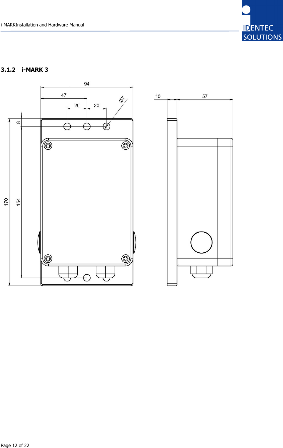
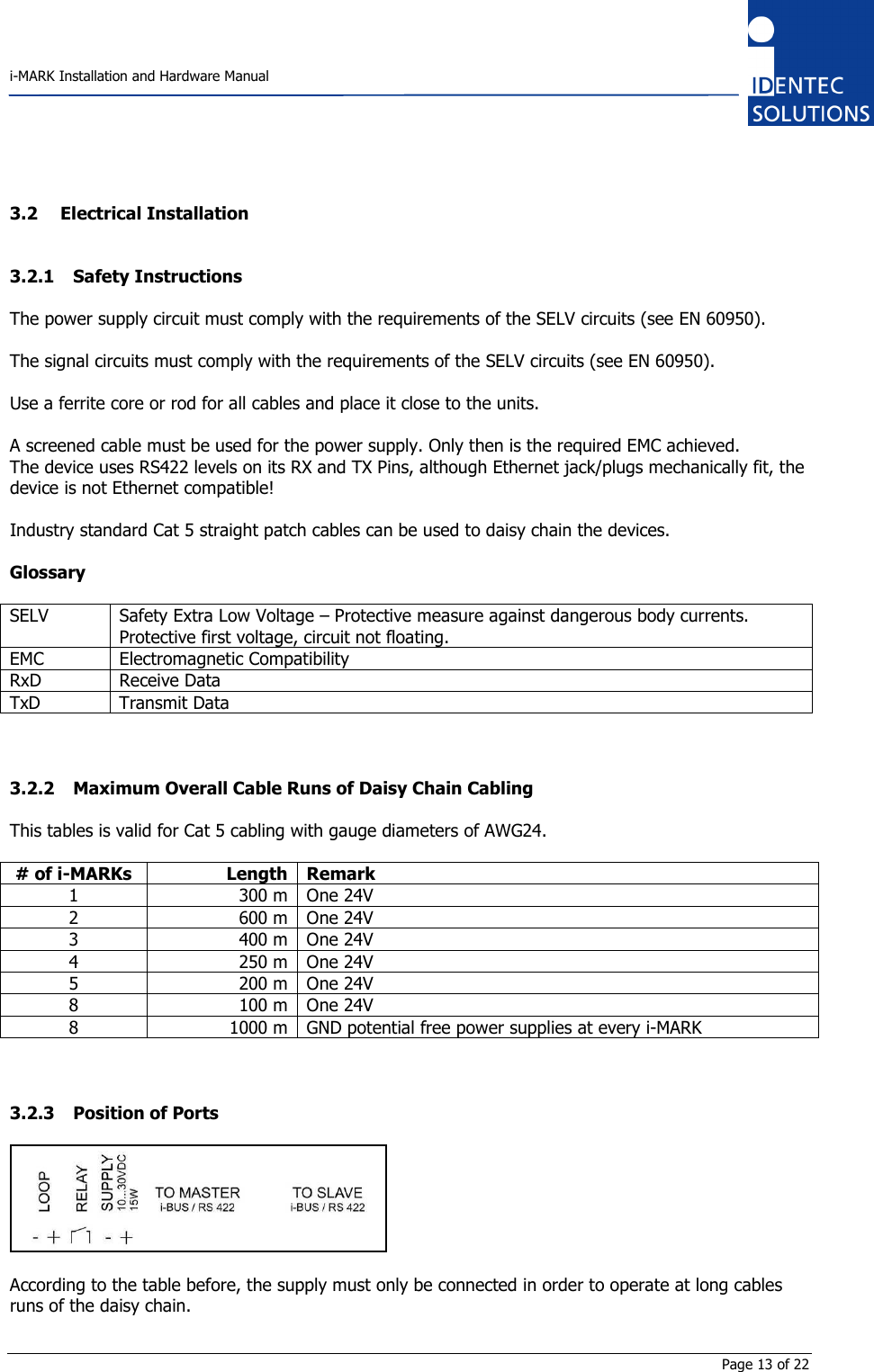
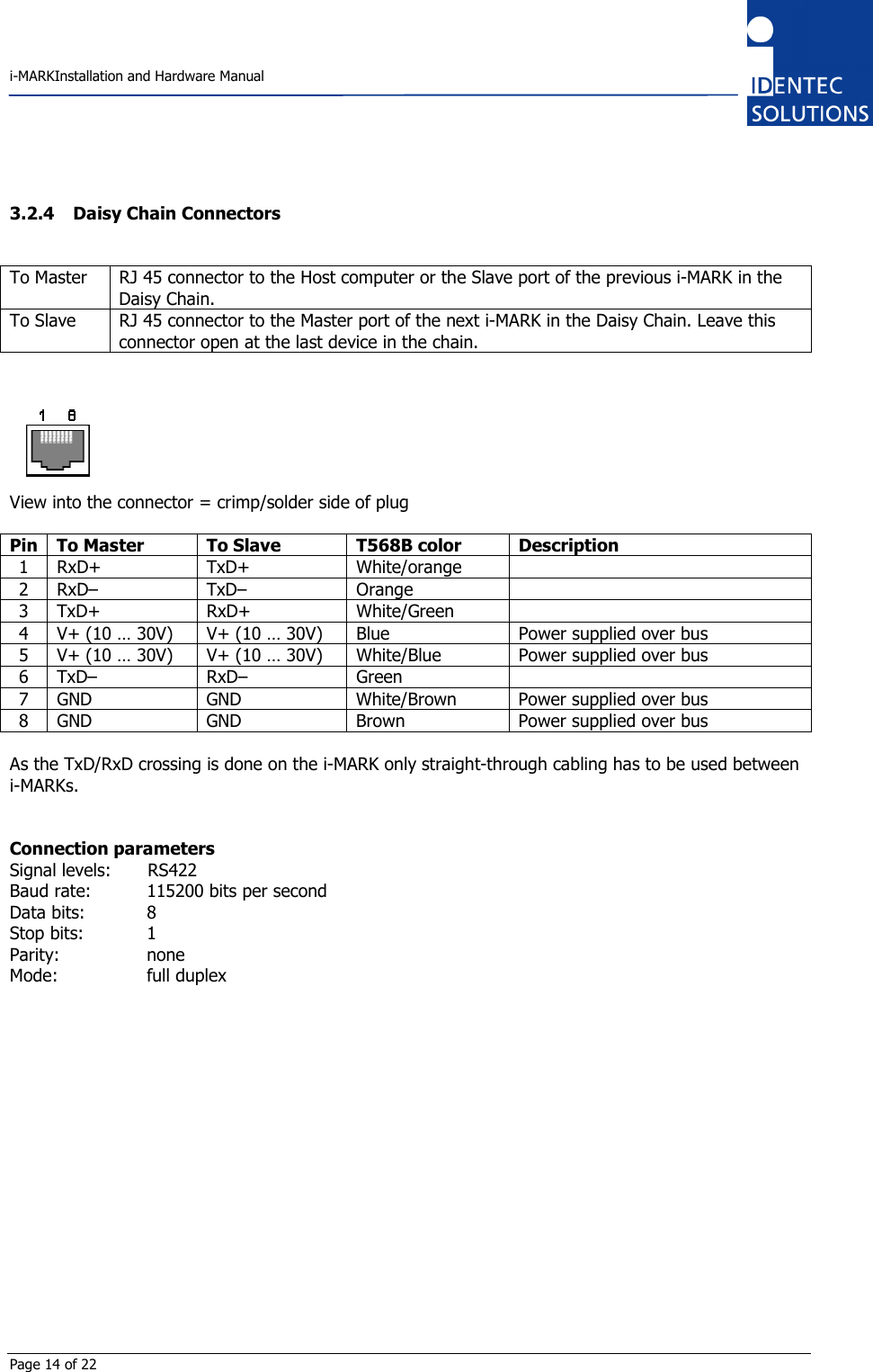
ILR IM3 User Manual
User Manual
Navigation menu
Upload a User Manual
Namespaces
Wiki Guide
HTML
PDF
Info
Views
User Manual
Discussion / Help
Navigation