Identec Solutions ILR-IM3 Position Marker User Manual CERTIFICATE OF COMPLIANCE
Identec Solutions, Inc. Position Marker CERTIFICATE OF COMPLIANCE
User Manual

Rhein Tech Laboratories, Inc. Client: Identec Solutions Inc.
360 Herndon Parkway Model Name: i-Mark 3
Suite 1400 Standards: FCC 15.209/IC RSS-210
FCC/IC ID: O2E-ILR-IM3/3538B-IM3 Herndon, VA 20170
http://www.rheintech.com Report #: 2007198
Page 28 of 34
Appendix H: Manual
Please refer to the following pages.

i-MARK 2, i-MARK 3
Installation and Hardware Manual

i-MARKInstallation and Hardware Manual
Page 2 of 22
Proprietary Notice
This document contains confidential information proprietary to IDENTEC SOLUTIONS and may not be
used or disclosed to other parties in whole or in part without prior written authorization from IDENTEC
SOLUTIONS.
Disclaimer and Limitation of Liability
IDENTEC SOLUTIONS AG and its affiliates, subsidiaries, officers, directors, employees and agents
provide the information contained in this Manual on an “as-is” basis and do not make any express or
implied warranties or representations with respect to such information including, without limitation,
warranties as to non-infringement, reliability, fitness for a particular purpose, usefulness,
completeness, accuracy or up-to-dateness. IDENTEC SOLUTIONS shall not in any circumstances be
liable to any person for any special, incidental, indirect or consequential damages, including without
limitation, damages resulting from use of or reliance on information presented herein, or loss of profits
or revenues or costs of replacement goods, even if informed in advance of the possibility of such
damages.
Trademarks
“IDENTEC SOLUTIONS”, “Intelligent Long Range”, “ILR” and the stylized “i” are registered trademarks
and “i-Q”, “i-D”, “i-B”, “i-CARD”, “i-PORT”, “i-LINKS”, “Solutions. It’s in our name.”, “Smarten up your
assets” are trademarks of IDENTEC SOLUTIONS, Inc. and/or IDENTEC SOLUTIONS AG.
Copyright Notice
Copyright © 2007 IDENTEC SOLUTIONS. All rights reserved.
No part of this document may be reproduced or transmitted in any form by any means, photographic,
electronic, mechanical or otherwise, or used in any information storage and retrieval system, without
the prior written permission of IDENTEC SOLUTIONS.
Reg. No. IM.0732.EN
Order Code:
Issue 0 / June 2007
– 25. June 2007 –
IDENTEC SOLUTIONS AG,
Millenium Park 2, 6890 Lustenau, Austria
Phone: +43 5577 87387- 0, Fax: +43 5577 87387-15
Email: info@identecsolutions.at
www.identecsolutions.com
Subject to alteration without prior notice.
© Copyright IDENTEC SOLUTIONS 2007
Printed in Germany

i-MARK Installation and Hardware Manual
Page 3 of 22
Radio Frequency Compliance Statement
IDENTEC SOLUTIONS, Inc. is the responsible party for the compliance of the following devices:
MODEL: i-MARK 2 i-MARK 3
FCC ID: O2E-ILR-IM2 O2E-ILR-IM3
CANADA: 3538B-IM2 3538B-IM3
EUROPE: CE 0678(!) CE 0678(!)
The user(s) of these products are cautioned to only use accessories and peripherals approved, in
advance, by IDENTEC SOLUTIONS, Inc. The use of accessories and peripherals, other than those
approved by IDENTEC SOLUTIONS, Inc., or unauthorized changes to approved products, may void the
compliance of these products and may result in the loss of the user(s) authority to operate the
equipment.
Operation is subject to the following conditions: (1) these devices may not cause harmful interference,
and (2) these devices must accept any interference, including interference that may cause undesired
operation of the device.
FCC Compliance
This equipment has been tested and found to comply with the limits for a Class A digital device,
pursuant to Part 15 of the FCC Rules. These limits are designed to provide reasonable protection
against harmful interference when the equipment is operated in a commercial environment. This
equipment generates, uses, and can radiate radio frequency energy and, if not installed and used in
accordance with the instruction manual, may cause harmful interference to radio communication.
Operation of this equipment in a residential area is likely to cause harmful interference in which case
the user will be required to correct the interference at his/her own expense.
For FCC compliance, the supplied ferrite cores must be placed onto the driver loops where the leads
attach to the i-MARK 3.
Warning: Changes or modifications to this unit not expressly approved by the party responsible for
compliance could void the user’s authority to operate the equipment.
Industry Canada Compliance
This Class A digital apparatus meets all requirements of the Canadian Interference-Causing Equipment
Regulations.
Cet appareil numérique de la classe A respecte toutes les exigences du Règlement sur le matériel
brouilleur du Canada.
European Notification according R&TTE Directive
This equipment complies to Art. 6.4 of R&TTE Directive (1999/5/EC). It is tested for compliance with the
following standards:
EN 300 220-1 V1.3.1 (2000-09), EN 300 220-3 V1.3.1 (2000-09), ETSI EN 301 489 V1.4.1 (2002-08), ETSI
EN 301 489 V1.4.1 (2002-08)
i-MARKInstallation and Hardware Manual
Page 4 of 22
This product contains components that are sensitive to electrostatic discharges. Please observe the
special instructions for their protection. Incorrect handling can damage the unit and cause the
invalidation of the warranty.
Minimum safety precautions against electrostatic discharge:
• Establish earth contact before you touch the unit. For example, touch the earthing screw on the
unit. Even better: Use an antistatic ribbon and earth yourself permanently for the time you
handle the unit.
• Avoid unnecessary contact with the unit connectors and assemblies inside the unit.
• Only open the unit if the operational settings (as described in the manual) expressly require this.
• Use antistatic tools for the setting of the unit. (Warning: Do not touch life-threatening voltages
with these tools).
• Do not store unit and components without protective packaging.
• Only remove unit and components from the packaging immediately prior to installation.
These notes are not sufficient to guarantee complete protection from electrostatic
discharges! We recommend the use of suitable protective equipment.

i-MARK Installation and Hardware Manual
Page 5 of 22
Contents
1
SAFETY INSTRUCTIONS ...............................................................................................7
2
INTRODUCTION............................................................................................................9
2.1
P
REPARATIONS
...............................................................................................................9
2.2
S
COPE OF
T
HIS
D
OCUMENT
...............................................................................................9
2.3
R
ESPONSIBILITY
.............................................................................................................9
2.4
U
PDATES
....................................................................................................................10
2.5
S
COPE OF
D
ELIVERY
—V
ISUAL
I
NSPECTION
..........................................................................10
2.6
A
SSOCIATED
D
OCUMENTS
...............................................................................................10
2.7
B
LUETOOTH
M
ODULE
.....................................................................................................10
2.8
I
NTERNAL
M
AINS
S
UPPLY
................................................................................................10
3
INSTALLATION ...........................................................................................................11
3.1
M
ECHANICAL
I
NSTALLATION
.............................................................................................11
3.1.1
i-MARK 2...................................................................................................................11
3.1.2
i-MARK 3...................................................................................................................12
3.2
E
LECTRICAL
I
NSTALLATION
..............................................................................................13
3.2.1
Safety Instructions.....................................................................................................13
3.2.2
Maximum Overall Cable Runs of Daisy Chain Cabling ...................................................13
3.2.3
Position of Ports ........................................................................................................13
3.2.4
Daisy Chain Connectors .............................................................................................14
4
INITIAL OPERATION ..................................................................................................15
4.1
G
ENERAL
....................................................................................................................15
4.2
T
OOLS REQUIRED
..........................................................................................................15
4.3
C
ONFIGURATION
...........................................................................................................15
4.3.1
Adjusting the Inductive Loop Field ..............................................................................15
4.3.2
Adjusting the Inductive Loop Field ..............................................................................15
4.3.3
Operation Mode—Continuous/host only.......................................................................16
4.3.4
Operation Mode—Slave/master ..................................................................................16
4.3.5
Synchronization Mechanism........................................................................................16
4.3.6
Slot Configuration Examples.......................................................................................17
4.4
C
HECKING THE
I
NSTALLATION
..........................................................................................18
5
TROUBLESHOOTING ...................................................................................................19
5.1
G
ENERAL
....................................................................................................................19
5.2
S
TATUS
D
ISPLAY
(LED
S
) ................................................................................................19
5.3
L
OOP
E
RROR
...............................................................................................................19
6
MAINTENANCE............................................................................................................20
6.1
G
ENERAL
....................................................................................................................20
6.2
T
AG
B
ATTERY
L
IFE
........................................................................................................20
6.3
P
RECAUTIONARY
M
AINTENANCE
........................................................................................20
6.4
E
XCHANGING A MARKER WITHIN THE DAISY CHAIN
.................................................................20
6.5
S
PARE
P
ARTS
...............................................................................................................21
6.5.1
Recommended spare parts stock ................................................................................21
6.5.2
Preparing the spare parts...........................................................................................21
6.5.3
Examination and repair of exchanged parts.................................................................21
6.6
R
ETURNS
....................................................................................................................21

i-MARKInstallation and Hardware Manual
Page 6 of 22
7
TECHNICAL SPECIFICATIONS ....................................................................................22
7.1
O
PERATING
D
ATA
.........................................................................................................22
7.2
E
LECTRICAL
D
ATA
.........................................................................................................22
7.3
M
ECHANICAL
D
ATA
........................................................................................................22
7.4
E
NVIRONMENTAL
C
ONDITIONS
.........................................................................................22

i-MARK Installation and Hardware Manual
Page 7 of 22
1 Safety Instructions
The system described in this manual is for exclusive operation by trained employees. Only qualified
personnel that know the potential dangers involved should perform the installation, settings,
maintenance and repair of the units used.
Operational Safety
The correct and safe use of these systems assumes that operating and service personnel follow the
safety measures described in the manual alongside the generally acceptable safety procedures.
If there is a possibility that safe operation cannot be guaranteed the system must be switched off and
secured against accidental use. Then the service unit responsible must be informed.
Safety Documents
This ILR system was designed, tested and supplied in perfect condition according to document IEC348
Safety Requirements for Electronic Units of Class 1.
Condensate / Change of Temperature
Moving the systems from a cold to a warm environment could lead to dangerous situations due to
condensation. Therefore it must be ensured that the system can adjust itself to the warmer
temperature.
Do not open the housing
There is no need to open the housing in order to set any ILR unit. No unit has any internal setting
elements or displays. All settings are performed using software via the Service Interface.
Earthing
Before establishing any connections the housing of the system must be earthed.
Connections / Power Supply
The supply circuits must comply with the conditions set out for the SELV circuits (see EN 60950).
The signal circuits must comply with the conditions set out for the SELV circuits (see EN 60950).
Use screened cables for the power supply. This is the only way to achieve the prescribed EMC.
During maintenance damage could occur if printed circuit boards or cables are connected or
disconnected whilst the power supply is still on. Therefore only work on the connection and the
components when they are not live.
Fuses
Only experts who are aware of the dangers involved may replace the fuses. It must be ensured that
only fuses of the required current rating and the correct type are used for replacement. The use of
repaired fuses and/or short-circuiting the fuse holders is prohibited.
Spare Parts
We recommend that only personnel, original products, spare and replacement parts authorized by
IDENTEC SOLUTIONS be used for installation, service and repair. Otherwise IDENTEC SOLUTIONS
does not accept any responsibility for materials used, work carried out or possible consequences.

i-MARKInstallation and Hardware Manual
Page 8 of 22
Electrostatic Discharge
Semi-conductors of the type MOS or CMOS as well as two-pin types and precision resistance are
sensitive to ESD. All components, printed circuit boards and auxiliary systems should therefore always
be classed as sensitive to electrostatic discharge.
Before opening the cover the unit should be placed onto an ESD-protected surface. As with all work on
modern electronic modules the use of ESD clamps and ESD mats during work on the unit is
recommended.
• Sufficiently protect all printed circuit boards that were removed from the unit from damage.
• Observe all normal precautions for the use of tools.
• Use ESD-protected packaging material.
Never use measuring units with low impedance for measuring or testing systems with semi-conductor
components. Never use high voltage testing units or dielectric test units to test systems with semi-
conductor components.
If it is necessary to check the isolating properties of the field wiring, the assemblies (electronic units
and sensors) should be disconnected.
Earth the test units.
IDENTEC SOLUTIONS does not accept returns of products where the regulations concerning the ESD
precautions and protective packaging materials were not followed.
ESD – Electrostatic Discharge
EMC – Electromagnetic Compatibility
SELV – Safety Extra Low Voltage – Protective measure against dangerous body currents, formerly: protective first voltage range
i-MARK Installation and Hardware Manual
Page 9 of 22
2 Introduction
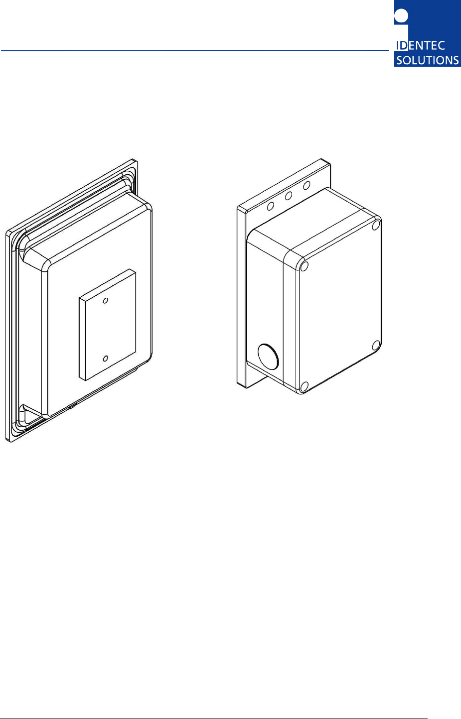
Compact Unit i-MARK 2
Central unit i-MARK 3
2.1 Preparations
This installation manual must be read carefully prior to starting the installation. The described
installation work assumes that installation materials like cable, antenna and data tag holder etc are
available
2.2 Scope of This Document
This document is the hardware description of both the i-MARK 2 and i-MARK 3. This document is
intended only for mechanical and electrical installation of this central units. A general system
description, especially of the Position Marker technology can be found in the extra system description;
please see below.
2.3 Responsibility
IDENTEC SOLUTIONS is not responsible for any errors occurring in this document.

i-MARKInstallation and Hardware Manual
Page 10 of 22
2.4 Updates
Updates will be provided on request. The information in this document can be changed without prior
notice from IDENTEC SOLUTIONS.
2.5 Scope of Delivery—Visual Inspection
Check delivery whether it is complete and for any damages. If the delivery is not complete or
damaged immediately inform the carrier. The customer service department of IDENTEC SOLUTIONS
should also be informed to facilitate the repair or exchange of the system.
2.6 Associated Documents
System description
• Reg-No: IM.0721.DE, German, order code:
• Reg-No: IM.0731.EN, English, order code:
Hardware description and installation manual (this document)
• Reg-No: IM.0732.DE, German, order code:
• Reg-No: IM.0732.EN, English, order code:
Firmware description and Programmer’s Guide
• Reg-No: IM.0733.DE, German, order code:
• Reg-No: IM.0733.EN, English, order code:
2.7 Bluetooth Module
The Bluetooth module is optional, when installed it enables any Bluetooth device to communicate with
a position marker using the protocol described before via RF.
Note: The Bluetooth interface only allows communicating with the device itself and does not forward
the messages on the RS422 bus.
2.8 Internal Mains Supply
The compact unit i-MARK 2 is available with an internal power supply to operate at a mains voltage of
230 VAC (Europe).
i-MARK Installation and Hardware Manual
Page 11 of 22
3 Installation
3.1 Mechanical Installation
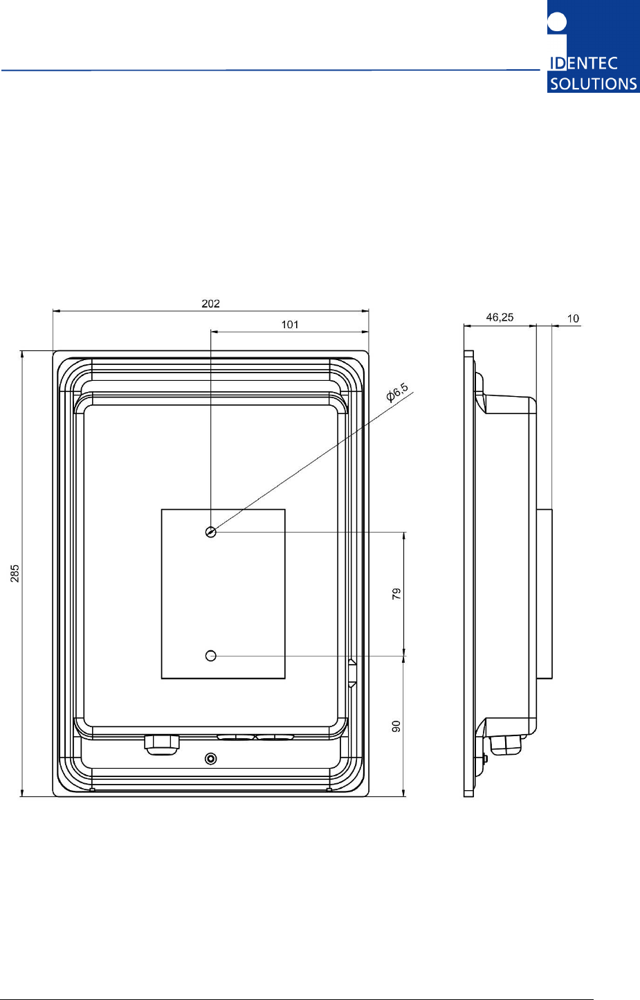
3.1.1 i-MARK 2
i-MARKInstallation and Hardware Manual
Page 12 of 22
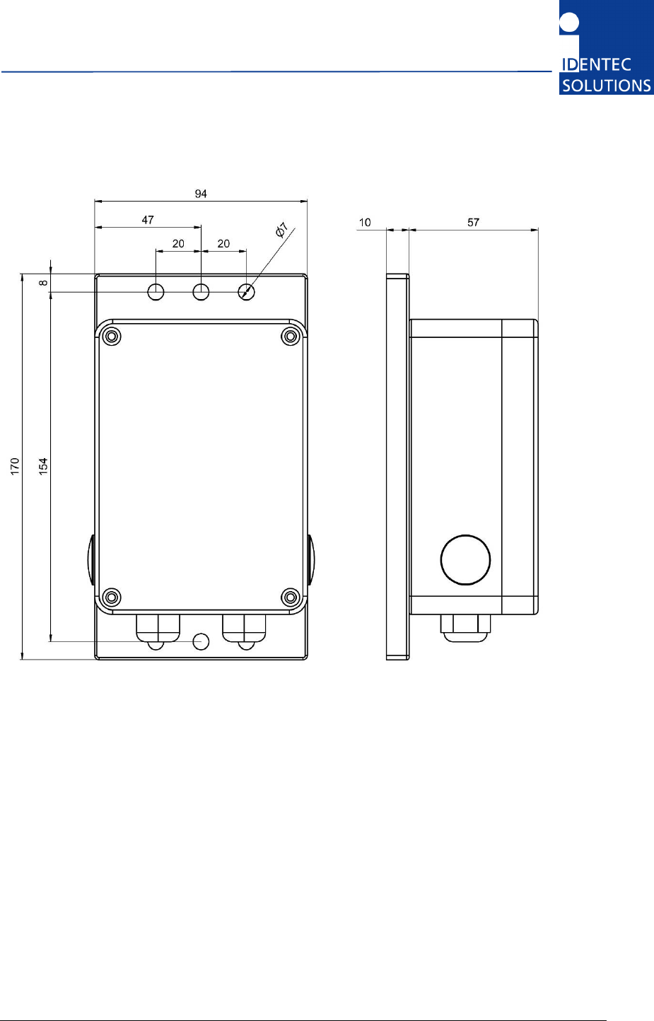
3.1.2 i-MARK 3
i-MARK Installation and Hardware Manual
Page 13 of 22
3.2 Electrical Installation
3.2.1 Safety Instructions
The power supply circuit must comply with the requirements of the SELV circuits (see EN 60950).
The signal circuits must comply with the requirements of the SELV circuits (see EN 60950).
Use a ferrite core or rod for all cables and place it close to the units.
A screened cable must be used for the power supply. Only then is the required EMC achieved.
The device uses RS422 levels on its RX and TX Pins, although Ethernet jack/plugs mechanically fit, the
device is not Ethernet compatible!
Industry standard Cat 5 straight patch cables can be used to daisy chain the devices.
Glossary
SELV Safety Extra Low Voltage – Protective measure against dangerous body currents.
Protective first voltage, circuit not floating.
EMC Electromagnetic Compatibility
RxD Receive Data
TxD Transmit Data
3.2.2 Maximum Overall Cable Runs of Daisy Chain Cabling
This tables is valid for Cat 5 cabling with gauge diameters of AWG24.
# of i-MARKs Length
Remark
1 300 m
One 24V
2 600 m
One 24V
3 400 m
One 24V
4 250 m
One 24V
5 200 m
One 24V
8 100 m
One 24V
8 1000 m
GND potential free power supplies at every i-MARK
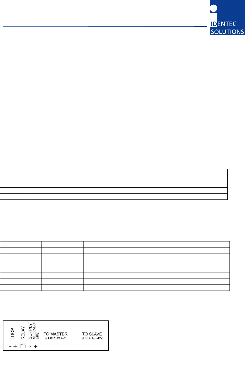
3.2.3 Position of Ports
According to the table before, the supply must only be connected in order to operate at long cables
runs of the daisy chain.

i-MARKInstallation and Hardware Manual
Page 14 of 22
3.2.4 Daisy Chain Connectors
To Master RJ 45 connector to the Host computer or the Slave port of the previous i-MARK in the
Daisy Chain.
To Slave RJ 45 connector to the Master port of the next i-MARK in the Daisy Chain. Leave this
connector open at the last device in the chain.
View into the connector = crimp/solder side of plug
Pin
To Master To Slave T568B color Description
1 RxD+ TxD+ White/orange
2 RxD– TxD– Orange
3 TxD+ RxD+ White/Green
4 V+ (10 … 30V) V+ (10 … 30V) Blue Power supplied over bus
5 V+ (10 … 30V) V+ (10 … 30V) White/Blue Power supplied over bus
6 TxD– RxD– Green
7 GND GND White/Brown Power supplied over bus
8 GND GND Brown Power supplied over bus
As the TxD/RxD crossing is done on the i-MARK only straight-through cabling has to be used between
i-MARKs.
Connection parameters
Signal levels: RS422
Baud rate: 115200 bits per second
Data bits: 8
Stop bits: 1
Parity: none
Mode: full duplex

i-MARK Installation and Hardware Manual
Page 15 of 22
4 Initial Operation
4.1 General
Do not open the housing.
Opening the housing is not necessary in order to set the i-MARK. The unit has no internal setting
elements or displays. All settings are performed using software via the service interface.
4.2 Tools required
Hardware
PDA running Windows CE with installed Bluetooth interface or,
PC running Windows XP with installed Bluetooth interface
Software
PDA Service Tool “i-MARK-Controller”
PC Service Tool “i-MARK Config”
4.3 Configuration
In a standard installation only this settings need configuring:
• Adjust the inductive loop field
• Give every i-MARK a unique ID
• Set transmission slots (required only if several loops are in close proximity)
4.3.1 Adjusting the Inductive Loop Field
The size of the loop field is adjusted by adjusting the loop current using one of the Service tools.
4.3.2 Adjusting the Inductive Loop Field
Every i-MARK in the entire application must have a unique ID in order to avoid confusion. This unique
ID value is an integer value.

i-MARKInstallation and Hardware Manual
Page 16 of 22
4.3.3 Operation Mode—Continuous/host only
Note: The default operation mode is “continuous”, as most i-MARK installations will be autonomous.
In the continuous operation mode the i-MARK will transmit the LF telegram based on the slot
configuration and synchronized time (refer to the section 4.3.5).
In cases where an application may need to have full control over when the i-MARK transmits the LF
telegram the i-MARK can be switched into host only mode. The host is then responsible for telling the
i-MARK when to transmit a LF telegram.
4.3.4 Operation Mode—Slave/master
Note: This default operation mode is master.
The recommended configuration is to have a host present on the RS422 bus. This allows for the
retrieval of device status information and detection of device failure in real time. In this application,
the host will be the master and must send the synchronization messages to the i-MARK and all of the
i-MARKs must be configured as slaves.
In applications where an i-HUB or host is not required on the bus, but synchronization needs to occur,
a single i-MARK on the bus can be configured as a master. An i-MARK which is configured as a master
must be the first device in the bus hierarchy. When configured as a master it is only able to
communicate with devices which are connected off of its slave port. As such, all other i-MARKs
connected must be configured as a slave device. This single master on the bus will be in charge of
broadcasting the synchronization messages on the bus.
In slave mode the position marker will only transmit the LF telegram based on the synchronization
scheme or host request depending in the operating mode.
In master mode the device will additionally transmit synchronization telegrams and this independently
on the operating mode it is configured in.
4.3.5 Synchronization Mechanism
Note: This setting is only of importance if several i-MARKs are in close proximity to each other. The
default factory setting is that all time slots are used.
The synchronization mechanism goal is to avoid having multiple i-MARKs in overlapped transmit areas
transmit at the same time and disturb each other.
For this task, all the devices must be synchronized, and follow the synchronization mechanism
described below.
The modules synchronization is done by having 1 master device (i-HUB or Host application or a
i-MARK in master mode) to broadcast on the bus a synchronization telegram on a regular interval.
Default configuration is, that a device send in each of the 12 slots.
The time is divided in 12 slots of 20 milliseconds each.

i-MARK Installation and Hardware Manual
Page 17 of 22
For each i-MARK the application must define in which slot the device will transmit the LF telegram
making sure that the devices will not disturb each other. If all i-MARKs are synchronized, the slot
sequences on all i-MARKs shall start at the same time.
4.3.6 Slot Configuration Examples
Configuration example with two (2) i-MARKS, none of them can transmit at the same
time.
Slot Number 1 2 3 4 5 6 7 8 9 10 11 12
Marker 1 T T T T T T
Marker 2 T T T T T T
Configuration example with 4 i-MARKs, none of them can transmit at the same time.
Slot number 1 2 3 4 5 6 7 8 9 10 11 12
Marker 1 T T T
Marker 2 T T T
Marker 3 T T T
Marker 4 T T T
Configuration example with 8 i-MARKs
The cross table below defines which devices cannot transmit at the same time.
Marker 1 2 3 4 5 6 7 8
1 X X X
2 X X X
3 X X X X X
4 X X X X X
5 X X X X X
6 X X X X X
7 X X X
8 X X X
Results in a slot configuration table:
Slot number 1 2 3 4 5 6 7 8 9 10 11 12
Marker 1 T T T
Marker 2 T T T
Marker 3 T T T
Marker 4 T T T
Marker 5 T T T
Marker 6 T T T
Marker 7 T T T
Marker 8 T T T
4.4 Verifying the Installation
After completing the installation the operation must be systematically checked. The installation check
can be divided into three sections:
• Visual test
• Basic operational check
• Detailed operational check
If the basic check of the operational behavior is to be carried out using a (portable) PC a final check
via the intended user control system should also be carried out.

i-MARK Installation and Hardware Manual
Page 19 of 22
5 Troubleshooting
5.1 General
This chapter covers how faults can be recognized and rectified. There are potentially four main
problem sources:
• The user control system, including task requirements, communication cables, peripheral units
with possible object recognition switches.
• The ILR system including peripheral units and their cables, also potential object recognition
switches.
• The environment including large objects between antenna and tag, electrical disturbance sources,
human intervention, etc.
• The quality of the technical design, including alignment between antenna, ratio of task
requirements/available communication time etc. The information about system performance is
contained in the relevant datasheets.
When planning the total system do not forget these problem sources and “Fault finding procedures on
system level” should possibly be included in the host system. How this could look in detail depends on
the relevant system concept and very likely varies from one system to another.
5.2 Status Display (LEDs)
LOOP This LED lights green during sending a LF telegram (about 20 ms). In the case of a
loop error (loop broken or the set point of the loop current couldn’t be reached) the
LED lights red when sending a LF telegram.
RUN This LED blinks green, indicating the system is running normal.
BUS Lights green during receive and orange during response – also for Bluetooth.
ERR Blinking: system error on start-up, firmware execution failed.
5.3 Loop Error
There are three types of possible errors. Every of the following errors will switch the LOOP LED to red.
Also the marker will try to continue sending.
Loop broken Loop current is too low or near zero
Loop current out of range When setting the loop current (power) the marker tries to control the
output signal in a way, that the preset current is measured during LF
transmission. This adjustment is only done once, if the loop current is
changed by the user. During normal operation the loop current is
observed every telegram. If then the loop current is ±20 % out of range
the error condition will set.
Loop shorten

i-MARKInstallation and Hardware Manual
Page 20 of 22
6 Maintenance
6.1 General
In principle, the ILR system is maintenance-free. When correctly installed it operates for many years
without any problems.
6.2 Tag Battery Life
The selected batteries are long life lithium batteries whose service life depends on the extent of the
data communication and the ambient temperature of the application area. If this temperature is
extreme the service life of the battery is slightly reduced.
The long-term load due to high temperatures should therefore be avoided. However, the service life of
the batteries in most industrial environments should be at least 6 years depending on the type of the
tag and the operating conditions mentioned on the data sheets of the tag.
6.3 Precautionary Maintenance
Regular checking of all ports and cables belonging to the system is recommended. Unstable
connections could lead to damage and malfunctions of the system and therefore should be repaired as
soon as possible.
A Brief Checklist
• Are all casing intact?
• Are all cables intact?
• Are all connectors intact?
• Are all connectors securely fastened?
• Are all screws still tight?
• Is there suddenly a malfunction at a specific unit?
6.4 Exchanging a marker within the daisy chain
• Stop the application program on the host
• Exchange the reader
• Restart the application program on the host. If the application on the host checks on startup the
marker serial numbers as recommended, it will detect the changed configuration and require
either manual intervention or automatically configure the new device.
• Firmware Update
The firmware is stored in a FLASH memory an can be updated if needed.

i-MARK Installation and Hardware Manual
Page 21 of 22
6.5 Spare Parts
6.5.1 Recommended spare parts stock
In order to keep the down time of the system during malfunctions as short as possible it is
recommended to have certain spare parts in stock. At least one central unit, one antenna and one
antenna cable should be available. With larger systems with more than approx. 15 i-MARKs the
doubling of the recommended stock quantity should be considered.
Furthermore, it is recommended to have several spare tags in stock,
corresponding to approx. 0.5 – 1 % of the total number of tags.
6.5.2 Preparing the spare parts
In general all spare parts can be used immediately after delivery from IDENTEC SOLUTIONS.
However, for the compact communicator there are various settings of the communication parameters.
In order to keep the down times short it is recommended to set these parameters before the
component is entered into the spare part stock system. In most cases all units within an identification
system are used in the same way so that only one setting is required.
6.5.3 Examination and repair of exchanged parts
The data tags and compact communicators are complex electronic power units on which the customer
can carry out only very limited repairs. Normally the repairs are carried out at IDENTEC SOLUTIONS or
possibly at a distributor.
Before a part is sent in for repair a short examination should be carried out.
6.6 Returns
Parts or main components returned for repair or exchange must be handled with great care. PC cards
must be returned in the appropriate ESD-protecting packaging material.
All returns should include a completed returns form (see appendix) and be sent to the local distributor
or to:
IDENTEC SOLUTIONS AG
Service Department
Millenium Park 2
6890 Lustenau
AUSTRIA / AUTRICHE
i-MARKInstallation and Hardware Manual
Page 22 of 22
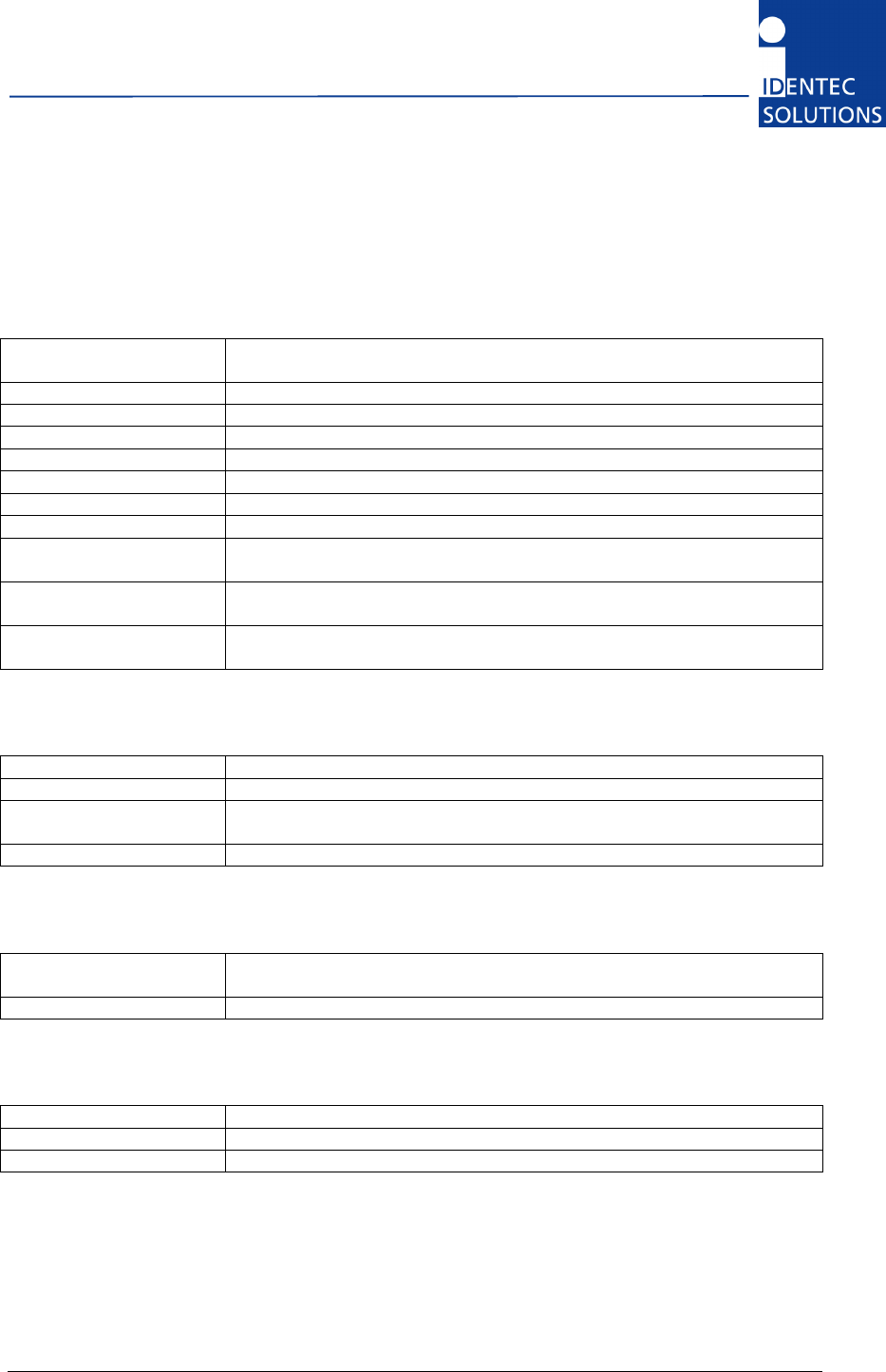
7 Technical Specifications
7.1 Operating Data
Range i-MARK 2: Adjustable by the loop current up to app 3 m
i-MARK 3: Depending on loop design and adjustable by the loop current
Operating Frequency 125 kHz
Number of loops 1
RF error protection 16 bit CRC
Certification CE, EN 300220 (EU), FCC Part 15 (US)
Firmware updates Via host computer interface
Configuration memory Non-volatile EEPROM memory
Status display 4 LEDs
Maximum number of
readers per daisy chain
16
Maximum cable runs
between two i-MARKS
300 m
Maximum overall cable
runs of daisy chain
1000 m (only with GND free power supplies at every i-MARK)
7.2 Electrical Data
Host interface RS422, Daisy Chain
Baud rate 115 kBaud, fixed
Supply voltage i-MARK 2: 10 to 30 V DC or 230 VAC (internal PSU, Europe only)
i-MARK 3: 10 to 20 V DC
Power consumption Max. 20 W per i-MARK
7.3 Mechanical Data
Overall dimensions i-MARK 2: 285 × 202 × 56.25 mm
i-MARK 3: 170 × 94 × 67 mm
Case material Plastics
7.4 Environmental Conditions
Operating temperature –20
°C to +60
°C
Humidity Up to 90% non-condensing
Protection class IP40, IP65 with additional protection for connector, Ref. IEC 529