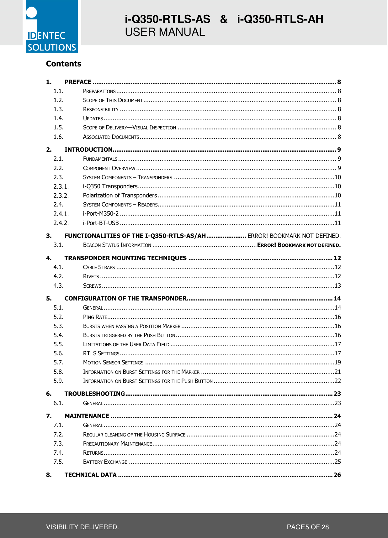
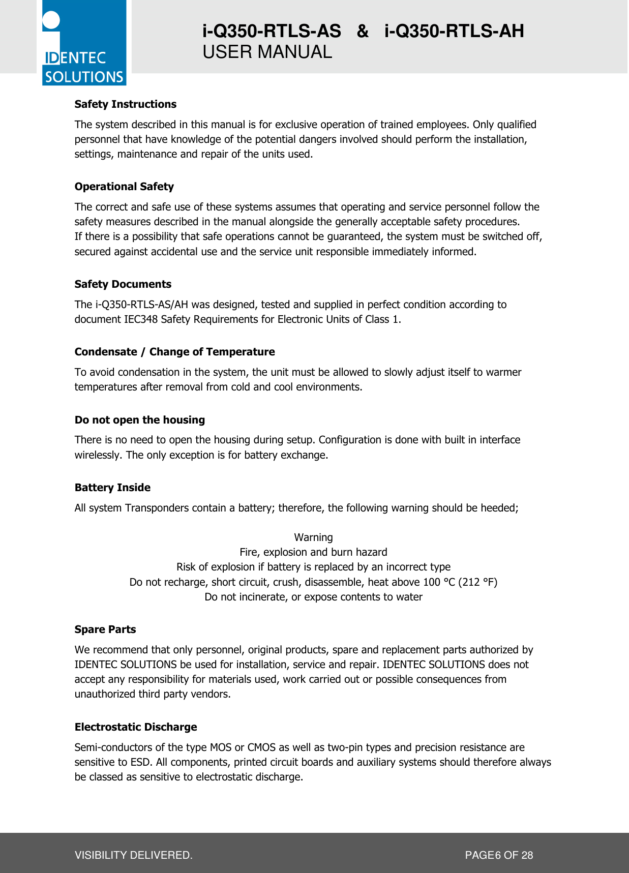
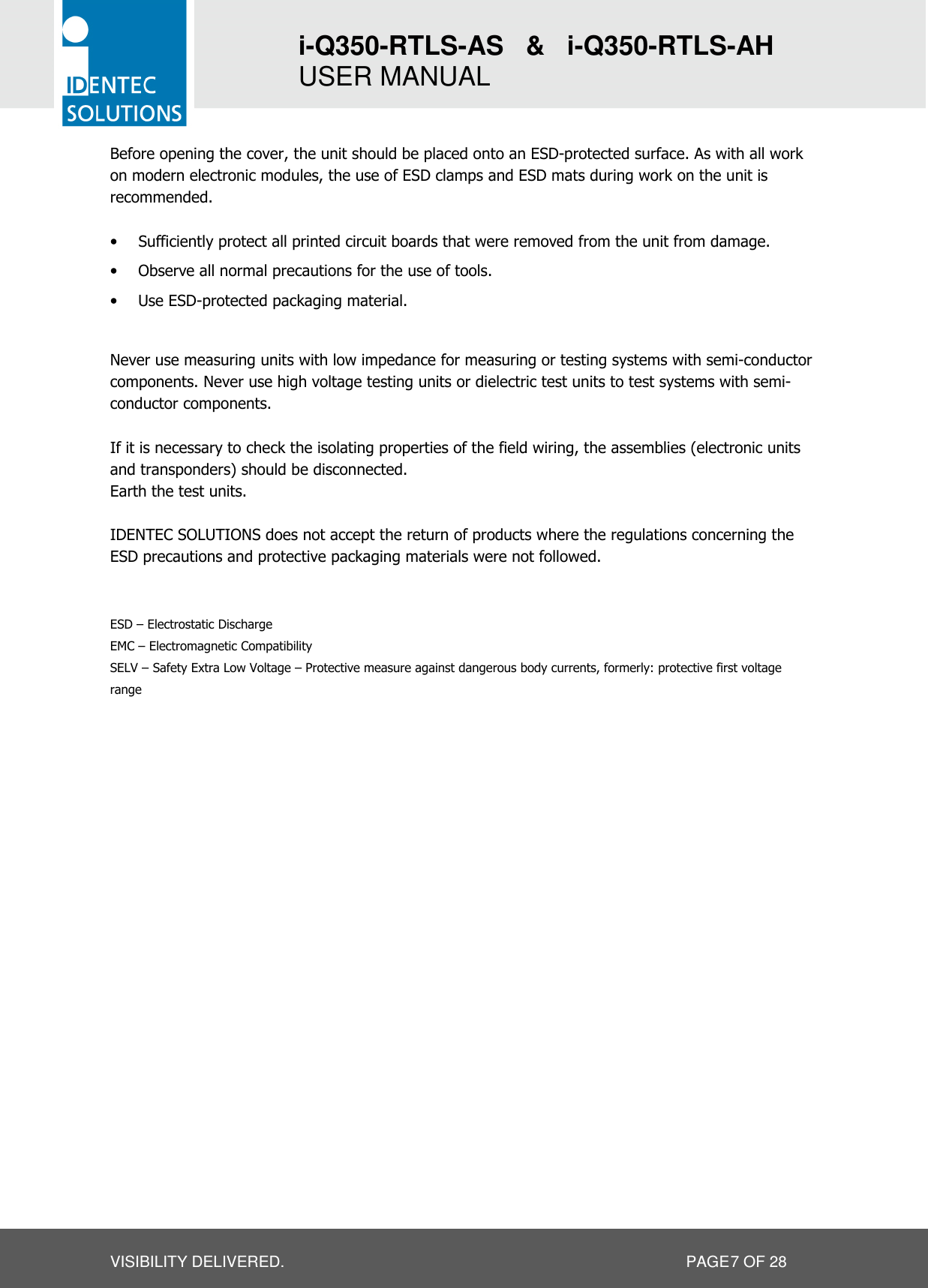
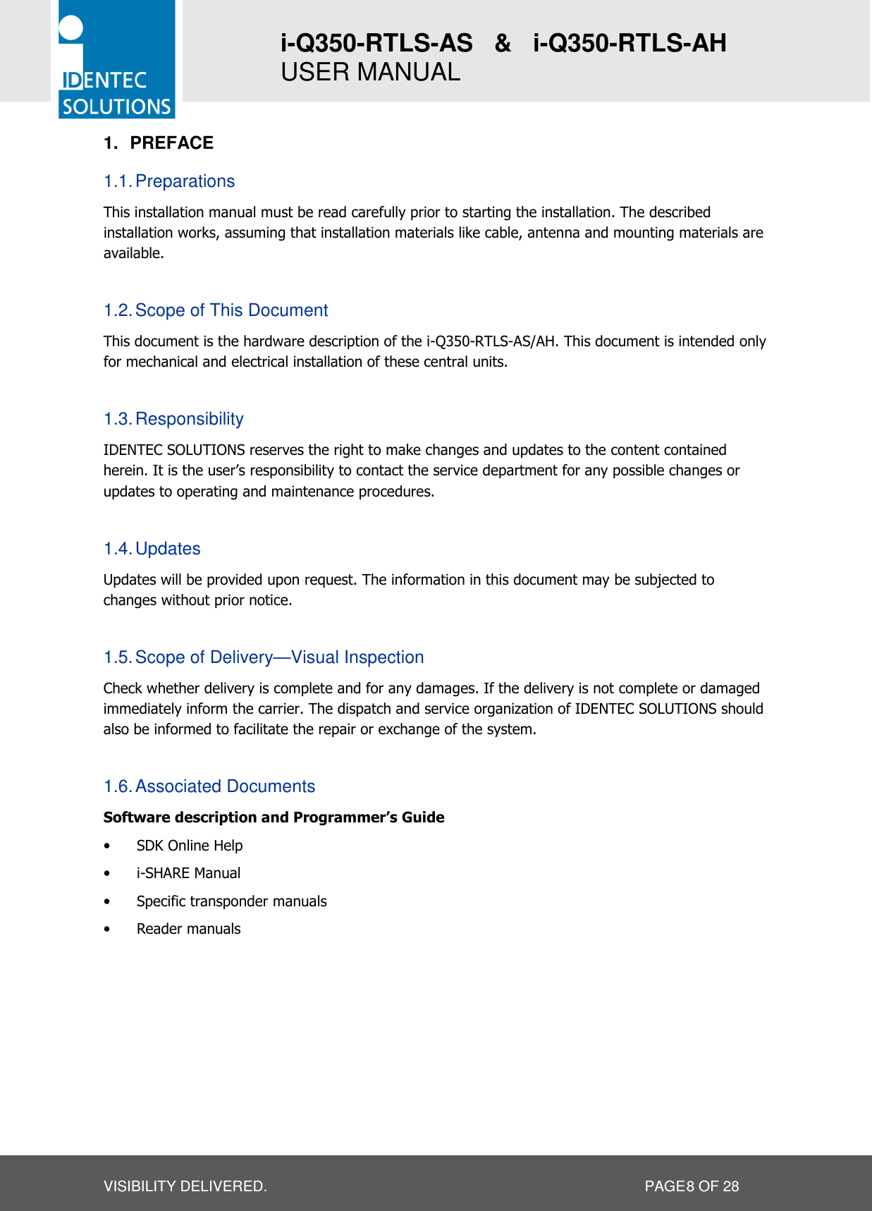
Identec Solutions ILR-IQ350LS Active transponder TAG User Manual M EN i Q350 RTLS AH AS V13cert
Identec Solutions AG Active transponder TAG M EN i Q350 RTLS AH AS V13cert
UserManual.wiki
>
Identec Solutions
>
ILR IQ350LS User Manual
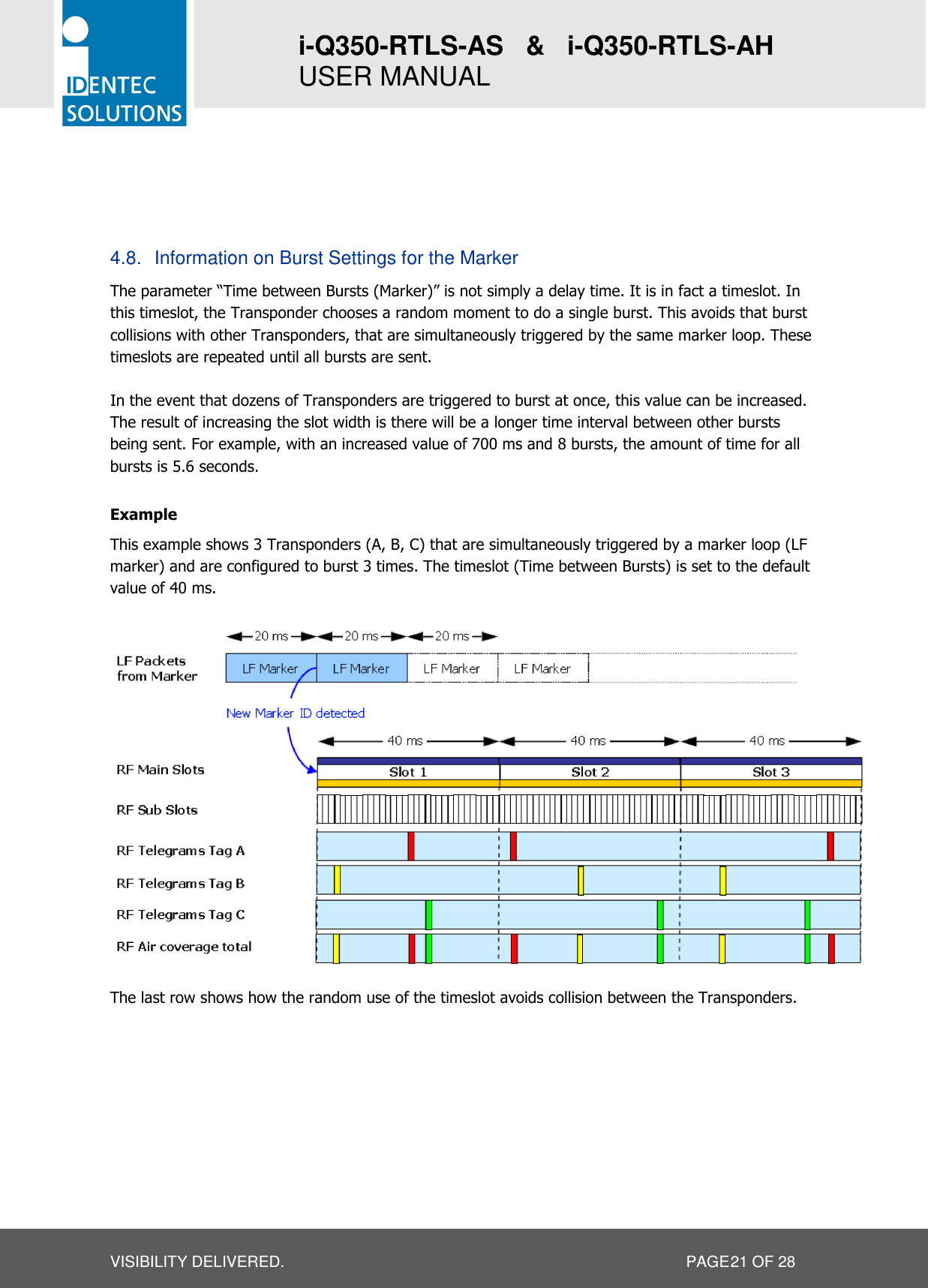
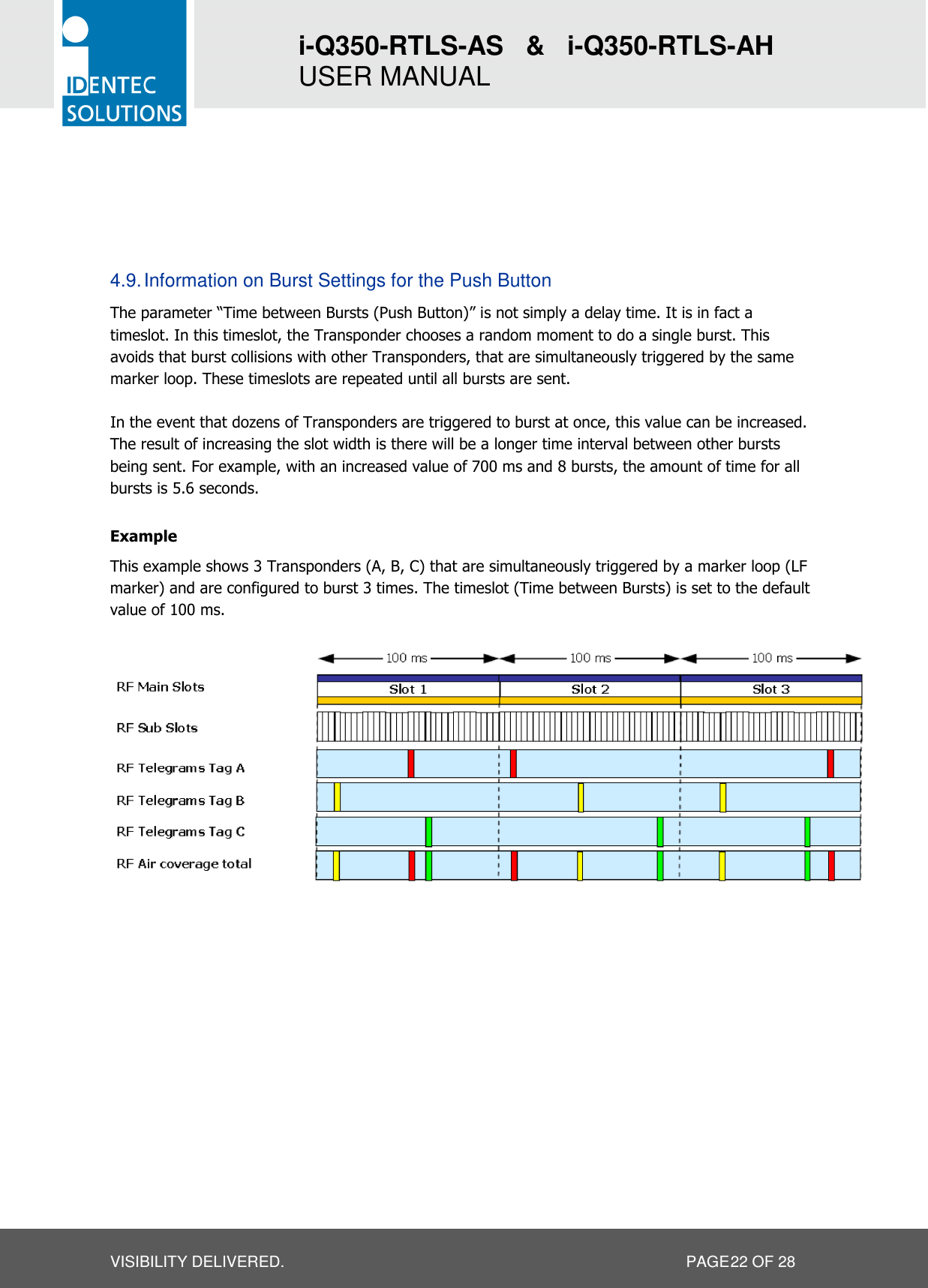
Users manual
Navigation menu
Upload a User Manual
Namespaces
Wiki Guide
HTML
PDF
Info
Views
User Manual
Discussion / Help
Navigation