Identec Solutions ILR-IQ350LS Active transponder TAG User Manual M EN i Q350 RTLS AH AS V13cert
Identec Solutions AG Active transponder TAG M EN i Q350 RTLS AH AS V13cert
Users manual
i-Q350-RTLS -AS
RTLS Transponder – Screw Fixing
i-Q350-RTLS -AH
RTLS Transponder – Hook Fixing
User Manual

i-Q350-RTLS-AS & i-Q350-RTLS-AH
USER MANUAL
VISIBILITY DELIVERED. PAGE 2 OF 28
Proprietary Notice
This document contains confidential information proprietary to IDENTEC SOLUTIONS and may not be
used or disclosed to other parties in whole or in part without the prior written authorization from
IDENTEC SOLUTIONS.
Disclaimer and Limitation of Liability
IDENTEC SOLUTIONS AG and its affiliates, subsidiaries, officers, directors, employees and agents do
not make any express or implied warranties or representations with respect to such information
including, without limitation, warranties as to non-infringement, reliability, suitability for a particular
purpose and accuracy. IDENTEC SOLUTIONS shall not under any circumstances be liable to any
person for any special, incidental, indirect or consequential damages, including without limitation,
damages resulting from use of or reliance on information presented herein, or loss of profits or
revenues or costs of replacement goods, even if informed in advance of the possibility of such
damages.
Trademarks
“IDENTEC SOLUTIONS”, “Intelligent Long Range”, “ILR” and the stylized “i” are registered
trademarks and “i-CARD”, “i-PORT”, “i-LINKS”, “Visibility Delivered.” are trademarks of IDENTEC
SOLUTIONS, Inc. and/or IDENTEC SOLUTIONS AG.
Copyright Notice
Copyright © 2016 IDENTEC SOLUTIONS. All rights reserved.
No part of this document may be reproduced or transmitted in any form by any means, photographic,
electronic, mechanical or otherwise, or used in any information storage and retrieval system, without
the prior written permission of IDENTEC SOLUTIONS.
Issue 1.3 / March 2017 (FEK)
Subject to alteration without prior notice.
© Copyright IDENTEC SOLUTIONS 2017
Printed in Austria
Radio Frequency Compliance Statement

i-Q350-RTLS-AS & i-Q350-RTLS-AH
USER MANUAL
VISIBILITY DELIVERED. PAGE 3 OF 28
IDENTEC SOLUTIONS is the responsible party for the compliance of the following devices:
MODEL: i-Q350-RTLS-AS & i-Q350-RTLS-AH
Region/Country Organization Marking
EUROPE: EC CE
USA: FCC FCC ID:
OO4-ILR-IQ350LS
Canada: Industry Canada IC:
3538A-IQ350LS
The user(s) of these products are cautioned to only use accessories and peripherals approved, in
advance, by IDENTEC SOLUTIONS. The use of accessories and peripherals, other than those approved by
IDENTEC SOLUTIONS, or unauthorized changes to approved products, may void the compliance of these
products and may result in the loss of the user(s) authority to operate the equipment.
European Notification according to R&TTE Directive
It is tested for compliance with the following standards:
ETSI EN 301 489-1 (V1.9.2), ETSI EN 301 489-3 (V1.6.1), ETSI EN 301 489-17 (V2.2.1)
ETSI EN 300 220-1 V2.4.1 (2012), ETSI EN 300 220-2 V2.4.1 (2012), ETSI EN 300 328 V1.9.1
EN 60950-1 (2006+A11/2009+A1/2010+A12/2011+A2/2013),
IEC 60950-1 (2005+A1/2009+A2/2013), EN 62311 (2008)
USA Notification
This device complies with part 15 of the FCC Rules. Operation is subject to the following two
conditions:
(1) This device may not cause harmful interference, and
(2) this device must accept any interference received, including interference that may cause
undesired operation.
Canada Certification
This device complies with Industry Canada’s license exempt RSS’s. Operation is subject to the
following two conditions:
(1) This device may not cause harmful interference, and
(2) this device must accept any interference received, including interference that may cause
undesired operation.
Le présent appareil est conforme aux CNR d‘Industrie Canada applicables aux appareils radio exempts
de licence. L‘exploitation est autorisée aux deux conditions suivantes:
(1) l‘appareil ne doit pas produire de brouillage, et
(2) l‘utilisateur de l‘appareil doit accepter tout brouillage radioélectrique subi, même si le brouillage
est susceptible d‘en compromettre le fonctionnement.

i-Q350-RTLS-AS & i-Q350-RTLS-AH
USER MANUAL
VISIBILITY DELIVERED. PAGE 4 OF 28
RF Exposure
To satisfy FCC and IC RF Exposure requirements for mobile devices, a separation distance of 20 cm
or more should be maintained between the antenna of this device and persons during operation. To
ensure compliance, operation at closer than this distance is not recommended. This transmitter must
not be co-located or operating in conjunction with any other antenna or transmitter.
Pour satisfaire aux exigences FCC et IC concernant l'exposition aux champs RF pour les appareils
mobiles, une distance de séparation de 20 cm ou plus doit être maintenu entre l'antenne de ce
dispositif et les personnes pendant le fonctionnement. Pour assurer la conformité, il est déconseillé
d'utiliser cet équipement à une distance inférieure. Cet émetteur ne doit pas être co-situé ou
fonctionner conjointement avec une autre antenne ou un autre émetteur.
This product contains components that are sensitive to electrostatic discharges. Please observe the
special instructions for their protection. Incorrect handling can damage the unit and cause the
invalidation of the warranty.
Minimum safety precautions against electrostatic discharge:
• Establish earth contact before you touch the unit. (For example, touch the earthing screw on the
unit.) Best practice is to use an antistatic ribbon and earth yourself permanently for the time you
handle the unit.
• Avoid unnecessary contact with the unit connectors and assemblies inside the unit.
• Only open the unit if the operational settings (as described in the manual) expressly requires it.
• Use antistatic tools for the setting of the unit. (Warning: Do not touch life-threatening voltages
with these tools).
• Do not store unit and components without protective packaging.
• Remove unit and components from the packaging only prior to installation.
These notes are not sufficient to guarantee complete protection from electrostatic
discharges! We recommend the use of suitable protective equipment.

i-Q350-RTLS-AS & i-Q350-RTLS-AH
USER MANUAL
VISIBILITY DELIVERED. PAGE 5 OF 28
Contents
1. PREFACE ....................................................................................................................................... 8
1.1. P
REPARATIONS
.......................................................................................................................... 8
1.2. S
COPE OF
T
HIS
D
OCUMENT
........................................................................................................... 8
1.3. R
ESPONSIBILITY
........................................................................................................................ 8
1.4. U
PDATES
................................................................................................................................. 8
1.5. S
COPE OF
D
ELIVERY
—V
ISUAL
I
NSPECTION
........................................................................................ 8
1.6. A
SSOCIATED
D
OCUMENTS
............................................................................................................. 8
2. INTRODUCTION ............................................................................................................................ 9
2.1. F
UNDAMENTALS
......................................................................................................................... 9
2.2. C
OMPONENT
O
VERVIEW
............................................................................................................... 9
2.3. S
YSTEM
C
OMPONENTS
–
T
RANSPONDERS
......................................................................................... 10
i-Q350 Transponders ............................................................................................................. 10
Polarization of Transponders .................................................................................................. 10
2.4. S
YSTEM
C
OMPONENTS
–
R
EADERS
.................................................................................................. 11
i-Port-M350-2 ....................................................................................................................... 11
i-Port-BT-USB ....................................................................................................................... 11
3. FUNCTIONALITIES OF THE I-Q350-RTLS-AS/AH ...................... ERROR! BOOKMARK NOT DEFINED.
3.1. B
EACON
S
TATUS
I
NFORMATION
.......................................................... E
RROR
!
B
OOKMARK NOT DEFINED
.
4. TRANSPONDER MOUNTING TECHNIQUES ................................................................................ 12
4.1. C
ABLE
S
TRAPS
......................................................................................................................... 12
4.2. R
IVETS
.................................................................................................................................. 12
4.3. S
CREWS
................................................................................................................................. 13
5. CONFIGURATION OF THE TRANSPONDER................................................................................. 14
5.1. G
ENERAL
................................................................................................................................ 14
5.2. P
ING
R
ATE
.............................................................................................................................. 16
5.3. B
URSTS WHEN PASSING A
P
OSITION
M
ARKER
..................................................................................... 16
5.4. B
URSTS TRIGGERED BY THE
P
USH
B
UTTON
........................................................................................ 16
5.5. L
IMITATIONS OF THE
U
SER
D
ATA
F
IELD
........................................................................................... 17
5.6. RTLS
S
ETTINGS
....................................................................................................................... 17
5.7. M
OTION
S
ENSOR
S
ETTINGS
......................................................................................................... 19
5.8. I
NFORMATION ON
B
URST
S
ETTINGS FOR THE
M
ARKER
.......................................................................... 21
5.9. I
NFORMATION ON
B
URST
S
ETTINGS FOR THE
P
USH
B
UTTON
................................................................... 22
6. TROUBLESHOOTING ................................................................................................................... 23
6.1. G
ENERAL
................................................................................................................................ 23
7. MAINTENANCE ........................................................................................................................... 24
7.1. G
ENERAL
................................................................................................................................ 24
7.2. R
EGULAR CLEANING OF THE
H
OUSING
S
URFACE
.................................................................................. 24
7.3. P
RECAUTIONARY
M
AINTENANCE
..................................................................................................... 24
7.4. R
ETURNS
................................................................................................................................ 24
7.5. B
ATTERY
E
XCHANGE
.................................................................................................................. 25
8. TECHNICAL DATA ....................................................................................................................... 26

i-Q350-RTLS-AS & i-Q350-RTLS-AH
USER MANUAL
VISIBILITY DELIVERED. PAGE 6 OF 28
Safety Instructions
The system described in this manual is for exclusive operation of trained employees. Only qualified
personnel that have knowledge of the potential dangers involved should perform the installation,
settings, maintenance and repair of the units used.
Operational Safety
The correct and safe use of these systems assumes that operating and service personnel follow the
safety measures described in the manual alongside the generally acceptable safety procedures.
If there is a possibility that safe operations cannot be guaranteed, the system must be switched off,
secured against accidental use and the service unit responsible immediately informed.
Safety Documents
The i-Q350-RTLS-AS/AH was designed, tested and supplied in perfect condition according to
document IEC348 Safety Requirements for Electronic Units of Class 1.
Condensate / Change of Temperature
To avoid condensation in the system, the unit must be allowed to slowly adjust itself to warmer
temperatures after removal from cold and cool environments.
Do not open the housing
There is no need to open the housing during setup. Configuration is done with built in interface
wirelessly. The only exception is for battery exchange.
Battery Inside
All system Transponders contain a battery; therefore, the following warning should be heeded;
Warning
Fire, explosion and burn hazard
Risk of explosion if battery is replaced by an incorrect type
Do not recharge, short circuit, crush, disassemble, heat above 100 °C (212 °F)
Do not incinerate, or expose contents to water
Spare Parts
We recommend that only personnel, original products, spare and replacement parts authorized by
IDENTEC SOLUTIONS be used for installation, service and repair. IDENTEC SOLUTIONS does not
accept any responsibility for materials used, work carried out or possible consequences from
unauthorized third party vendors.
Electrostatic Discharge
Semi-conductors of the type MOS or CMOS as well as two-pin types and precision resistance are
sensitive to ESD. All components, printed circuit boards and auxiliary systems should therefore always
be classed as sensitive to electrostatic discharge.

i-Q350-RTLS-AS & i-Q350-RTLS-AH
USER MANUAL
VISIBILITY DELIVERED. PAGE 7 OF 28
Before opening the cover, the unit should be placed onto an ESD-protected surface. As with all work
on modern electronic modules, the use of ESD clamps and ESD mats during work on the unit is
recommended.
• Sufficiently protect all printed circuit boards that were removed from the unit from damage.
• Observe all normal precautions for the use of tools.
• Use ESD-protected packaging material.
Never use measuring units with low impedance for measuring or testing systems with semi-conductor
components. Never use high voltage testing units or dielectric test units to test systems with semi-
conductor components.
If it is necessary to check the isolating properties of the field wiring, the assemblies (electronic units
and transponders) should be disconnected.
Earth the test units.
IDENTEC SOLUTIONS does not accept the return of products where the regulations concerning the
ESD precautions and protective packaging materials were not followed.
ESD – Electrostatic Discharge
EMC – Electromagnetic Compatibility
SELV – Safety Extra Low Voltage – Protective measure against dangerous body currents, formerly: protective first voltage
range

i-Q350-RTLS-AS & i-Q350-RTLS-AH
USER MANUAL
VISIBILITY DELIVERED. PAGE 8 OF 28
1. PREFACE
1.1. Preparations
This installation manual must be read carefully prior to starting the installation. The described
installation works, assuming that installation materials like cable, antenna and mounting materials are
available.
1.2. Scope of This Document
This document is the hardware description of the i-Q350-RTLS-AS/AH. This document is intended only
for mechanical and electrical installation of these central units.
1.3. Responsibility
IDENTEC SOLUTIONS reserves the right to make changes and updates to the content contained
herein. It is the user’s responsibility to contact the service department for any possible changes or
updates to operating and maintenance procedures.
1.4. Updates
Updates will be provided upon request. The information in this document may be subjected to
changes without prior notice.
1.5. Scope of Delivery—Visual Inspection
Check whether delivery is complete and for any damages. If the delivery is not complete or damaged
immediately inform the carrier. The dispatch and service organization of IDENTEC SOLUTIONS should
also be informed to facilitate the repair or exchange of the system.
1.6. Associated Documents
Software description and Programmer’s Guide
• SDK Online Help
• i-SHARE Manual
• Specific transponder manuals
• Reader manuals

i-Q350-RTLS-AS & i-Q350-RTLS-AH
USER MANUAL
VISIBILITY DELIVERED. PAGE 9 OF 28
2. INTRODUCTION
2.1. Fundamentals
The IDENTEC SOLUTIONS’ SensorSMART Platform is the latest development in asset management,
localization and process optimization. Developed to deliver the last mile in industrial communication,
the SensorSMART Platform fulfills a niche not previously addressed by available networks.
The SensorSMART Platform takes the complexity out of managing assets, personnel safety monitoring
and/or the tracking of valuable cargo and the need for multiple technologies. The unique combination
of active RFID, RTLS and WSN in one platform eliminates the necessity for complex deployments of
multiple technologies, or the need to compromise with one technology’s specific functionalities. The
pinnacle of the SensorSMART Platform is that it captures the best of RFID, WSN, and RTLS while also
avoiding the less desirable features of each technology. Third party application development is also
simplified for added flexibility.
2.2. Component Overview
i-Q350-RTLS-AS & i-Q350-RTLS-AH
USER MANUAL
VISIBILITY DELIVERED. PAGE 10 OF 28
2.3. System Components – Transponders
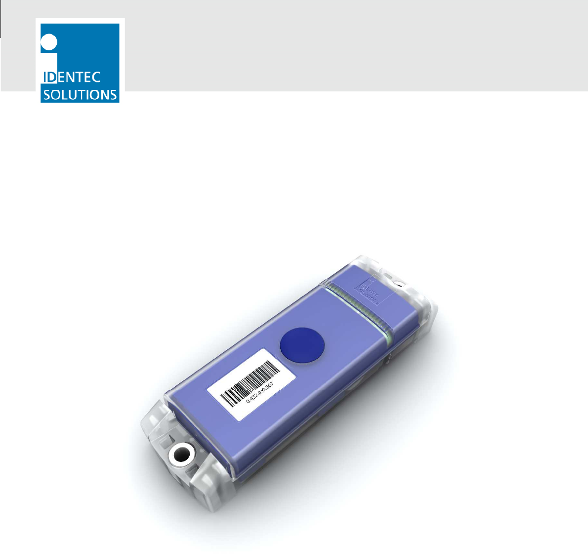
i-Q350 Transponders
IDENTEC SOLUTIONS’ Real Time Locating System (RTLS) allows long-range localization in
both indoor and out- door environments. Highly robust and value driven, the SensorSMART
RTLS is designed to offer maximum reliability and functionally.
Highly accurate, the RTLS enables real-time data collection and visibility with minimal human
intervention. IDENTEC SOLUTIONS’ RTLS is well suited for a variety of wireless applications
including:
• Identification
• Tracking
• Localization of high value assets and personnel.
The high speed localization delivers instant identification as well as the precise location of
assets or personnel within a 1m (3ft) radius.
Easy to integrate, the RTLS system has a rugged design that delivers outstanding
performance even in the most challenging industrial environments.
The i-Q350L RTLS in conjunction with the
i-SAT 300 RTLS reference generator allows communication even with rapidly-moving
Transponders.
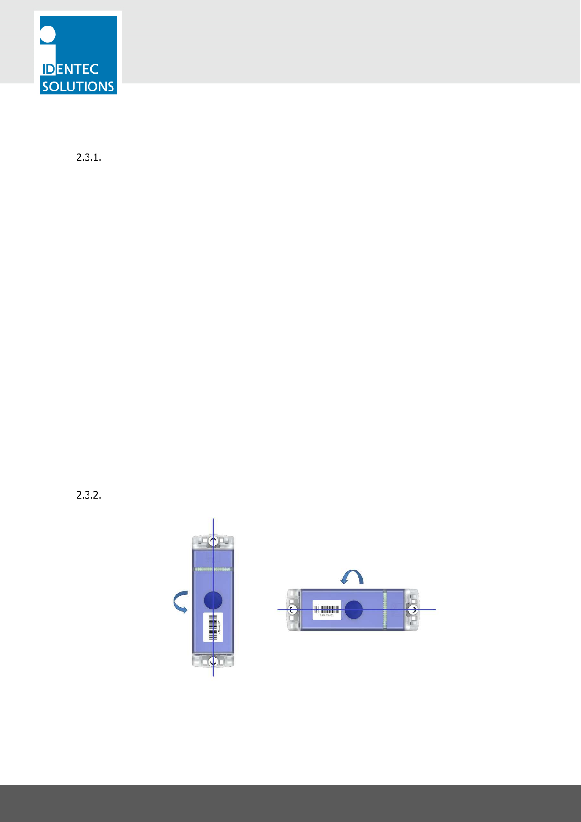
Polarization of Transponders
Polarization is dependent on orientation and is rotation symmetrical.
Vertically Polarized
Horizontally Polarized
i-Q350-RTLS-AS & i-Q350-RTLS-AH
USER MANUAL
VISIBILITY DELIVERED. PAGE 11 OF 28
2.4. System Components – Readers
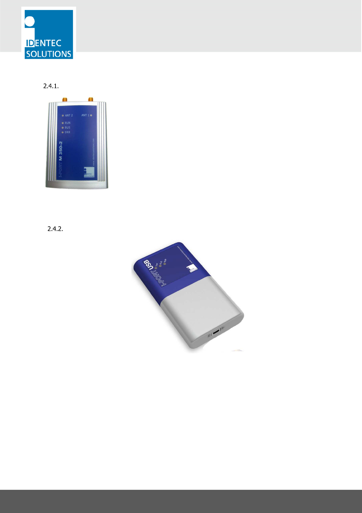
i-Port-M350-2
The i-PORT M350-2 is a reader for the i-Q350 and i-B350 series of
IDENTEC SOLUTIONS’s Response and Broadcast Transponders. Built into a
compact housing, the i-PORT M350-2 reads and writes data to the
transponders at distances of up to 500 meters (1640 feet) on two
antennas. Connection to the host system is established via a RS422
interface, resulting in the capability to connect up to 8 readers in a Daisy
Chain using commercially available CAT 5 cables and connectors.
A simple master/slave protocol enables data exchange. Not only does the
protocol contain the data received from the transponder, but it can also
provide information about the time of data reception, field strength and
information about the number of times the transponder has been received
by the reader.
i-Port-BT-USB
The battery powered mobile reader with Bluetooth and USB interface communicates with a
wide spectrum of handheld devices and tablet computers. It is ideally suited for mobile
applications such as laydown yards and personnel safety.
With its integrated Bluetooth interface, the mobile reader can communicate with a wide range
of mobile devices independent of platform or operating system.
The compact and robust housing with internal antenna is designed to be mounted onto a
handheld device or a tablet computer. The small form factor also allows users to carry the
reader in a pocket.
i-Q350-RTLS-AS & i-Q350-RTLS-AH
USER MANUAL
VISIBILITY DELIVERED. PAGE 12 OF 28
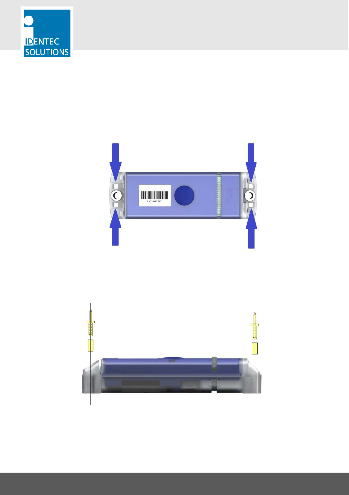
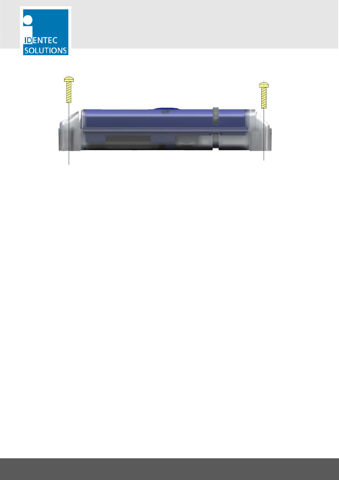
3. TRANSPONDER MOUNTING TECHNIQUES
The Transponder can be mounted either with cable straps using the 2 slots at each end, by using
rivets or screws described in the following 3 subchapters.
3.1. Cable Straps
3.2. Rivets
i-Q350-RTLS-AS & i-Q350-RTLS-AH
USER MANUAL
VISIBILITY DELIVERED. PAGE 13 OF 28
3.3. Screws

i-Q350-RTLS-AS & i-Q350-RTLS-AH
USER MANUAL
VISIBILITY DELIVERED. PAGE 14 OF 28
4. CONFIGURATION OF THE TRANSPONDER
4.1. General
The i-Q350-RTLS-AS/AH is not configured directly. It is configured wirelessly using an ILR GEN3
compatible device, e.g. an i-PORT M350 or i-Port-USB-BT
Things to be configured
• Beacon ping rate (It is recommended to set it at more than 20 seconds. In case there are more
than 500 Transponders in the antenna field it is recommended to set it at more than 60 seconds)
• Monitoring data:
- Monitoring interval (15 min to 2 hours, in steps of 1 minute)
- Data to be monitored
Important Note
Do not open the housing! Configuration is done wirelessly.
The Response mode of the i-Q350-RTLS-AS/AH offers the following features for configuration:
• Broadcast mode can be configured for simultaneous operation. In this case the Transponder
responds to commands from a reader as well as broadcasting configurable data at a regular
interval.
• Marker technology for locating the Transponder in an inductive loop and measuring travel time
between gates.
• Bursts triggered by a marker field can be configured independent of regular broadcast pings.
• Bursts triggered by the push button can be configured independent of regular broadcast pings.
Tools Needed
• PC running Microsoft Windows, with SensorSMART Tools installed
• Connection to an i-PORT-M350 or i-Port-BT-USB, to communicate with the Transponders
i-Q350-RTLS-AS & i-Q350-RTLS-AH
USER MANUAL
VISIBILITY DELIVERED. PAGE 15 OF 28
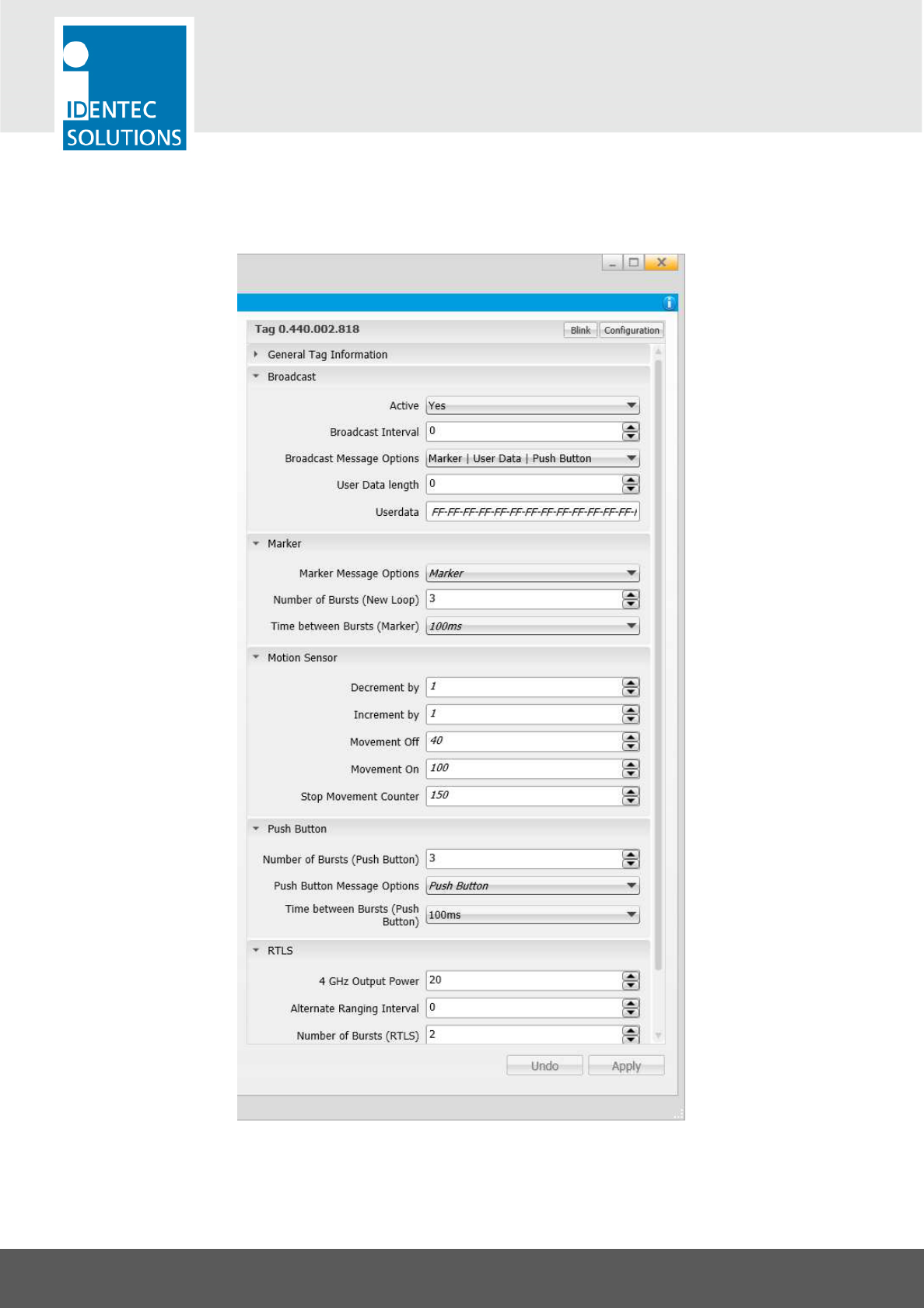
Overview on the Configuration Software

i-Q350-RTLS-AS & i-Q350-RTLS-AH
USER MANUAL
VISIBILITY DELIVERED. PAGE 16 OF 28
4.2. Ping Rate
Note: These settings can be found in the ILR Tag Configuration software tool in the section
“Broadcast”
• Active: Activates or de-activates the broadcast function that regularly sends out messages.
• Broadcast Interval: 0 = no broadcast messages are sent, value > 0 = Broadcast interval in
seconds. This can be set in steps of 0.5 sec, from 0.5 sec up to 300 sec.
• Broadcast Message Options: The options in this field depend on the capabilities of the
Transponder. The subchapter “Limitations of the User Data Field” lists the possible options of this
Transponder type.
• User Data Length: Configure the number of Bytes from the “User Data” that is sent with a
broadcast message. The number starts from Byte 0 (zero). The limits of the User Data length
are described at the end of this chapter.
4.3. Bursts when passing a Position Marker
Note: These settings can be found in the ILR Tag Configuration software tool in the section “Marker”
• Number of Bursts (New Loop): 0 = no bursts, max. 15 bursts
• Time between Bursts (Marker): This sets a timeslot inside which the Transponder sends out a
single burst. This gives a random delay between every single burst message to avoid collisions
with Transponders that are triggered by the same source to burst. Possible settings are 40, 100,
200, 300, 400, 500, 600, and 700 ms. Pls. read the details in the following subchapter
“Information on Burst Settings”.
• Marker Message Options: Entering a marker field triggers a burst. This parameter determines
the contents of the burst messages.
4.4. Bursts triggered by the Push Button
Note: These settings can be found in the ILR Tag Configuration software tool in the section “Push
Button”
• Number of Bursts (Push Button): 0 = no bursts, max. 15 bursts
• Time between Bursts (Push Button): This sets a timeslot within the Transponder sends a single
burst. This gives a random delay between every single burst message to avoid collisions with
Transponders that are triggered by the same source to burst. Possible settings are 100, 200,
300, 400, 500, 600, and 700 ms. Please read the details in the following subchapter
“Information on Burst Settings”.
• Push Button Message Options: Pushing the button triggers a burst. This parameter determines
the contents of the burst messages.
i-Q350-RTLS-AS & i-Q350-RTLS-AH
USER MANUAL
VISIBILITY DELIVERED. PAGE 17 OF 28
4.5. Limitations of the User Data Field
The total length of the broadcast message (burst or ping) is limited to 50 Bytes. Depending on the
broadcast message options, these are the allowed number of bytes for the user data:
Message Type Length of User Data
User Data only max. 50 Bytes
Marker | User Data max. 38 Bytes
Push Button | User Data max. 43 Bytes
Push Button | User Data | Marker max. 32 Bytes
4.6. RTLS Settings
Note: These settings can be found in the ILR Tag Configuration software tool in the edit block “RTLS”
The RTLS Transponder allows precise location calculation by ranging to up 15 reference nodes (i-SAT
300, i-PORT M 350 RTLS) at the same time. By default, this is done at an interval set by the
parameter “Ranging Interval”. In addition, the RTLS Transponders contain a motion sensor with a
software filter (see next subchapter) that switches between standard and alternate ranging intervals.
This is set with the parameters “Ranging Behavior”, “Ranging Interval” and “Alternate Ranging
Interval”. Ranging describes the process used to measure the distance between a Transponder and a
reader through the exchange of a specific set of messages. A ranging can be initiated based on time
(interval) or event (motion or application request)”.
Adjustable parameters in the section “RTLS” are:
• 2.4 GHz Output Power: This is the Tx power for the RTLS ranging. Increasing the output power
will greatly impact the communication range, but also have a massive impact on the power
consumption. The following table shows the power consumption during a transmission depending
of the output power.
Output power in
dBm
Power consumption increase compared to 0
dBm
Estimated range*
0 0 % 40 m
10 9 % 170 m
* Estimated range in outdoor operation and in line of sight
• Ranging Behavior:
The ranging process consists of multiple bidirectional communications, in order to calculate the distance
between the Transponder and the reader. i-Q350-RTLS Transponders are able to identify if they are in
i-Q350-RTLS-AS & i-Q350-RTLS-AH
USER MANUAL
VISIBILITY DELIVERED. PAGE 18 OF 28
motion or stand still. In the case of movement, the Transponder will switch to the “in motion” behavior
and use the alternate ranging interval. Two behaviors are available and described hereafter.
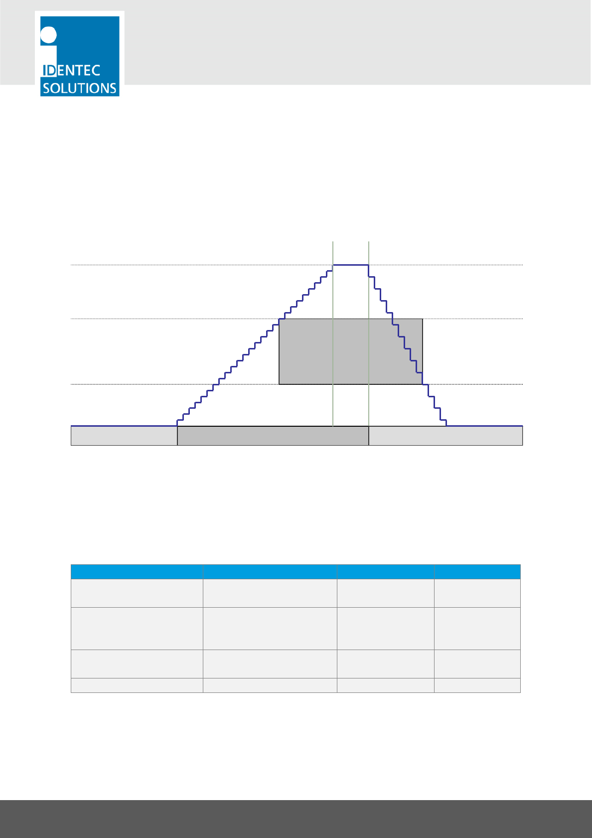
Continuous ranging behavior:
While in motion, the i-Q350-RTLS Transponder will perform ranging using the interval specified in
“alternate ranging interval”. After the Transponder detects that it has stopped moving, it will perform
ranging using the standard ranging interval.
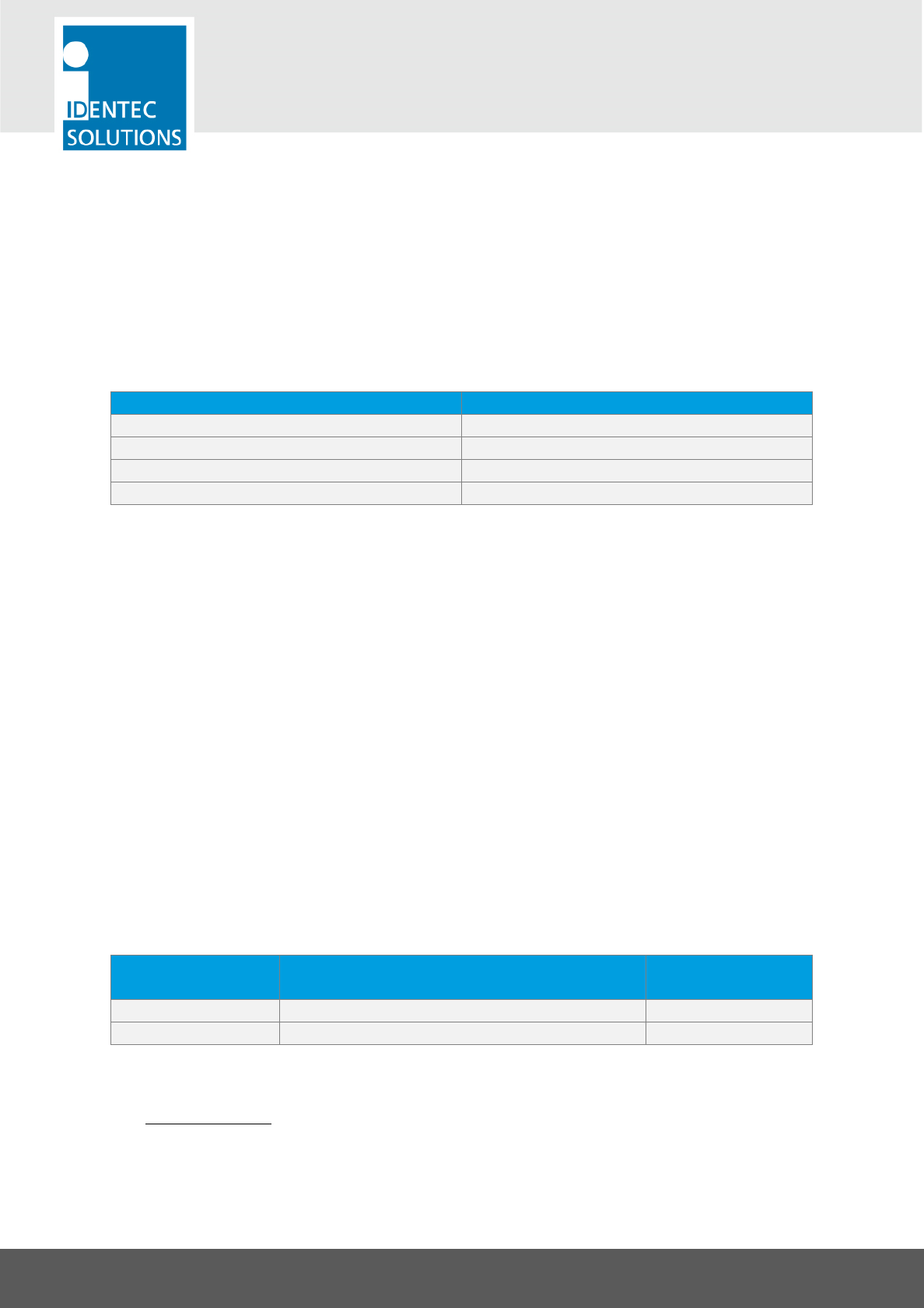
The following figure represents the behavior of the Transponder over time. The ranging is in orange,
while the bursts on RTLS event are in blue. This example shows 3 UHF bursts.
In this mode, the Transponder will broadcast distances measured after the ranging is done. As soon
as the Transponder considers it has stopped moving, it resumes its standard behavior.
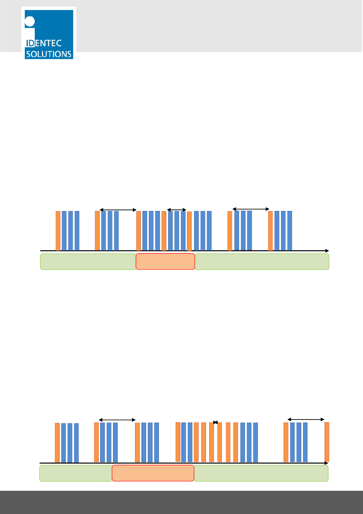
On Stop ranging behavior:
The i-Q350-RTLS Transponder will keep its standard ranging interval while moving. As soon as the i-
Q350 RTLS detects that it has stopped moving, it will perform 6 measurements with the interval
specified in the “alternate ranging interval”.
The following figure represents the behavior of the Transponder over time. The ranging is in orange,
while the bursts on RTLS event are in blue. This example shows 3 UHF bursts.
Tag stands still Tag stands still
Tag is in motion
Ranging
Ranging interval
Alternate ranging
interval
RTLS Event
Bursts
Ranging interval
Ranging interval
Tag stands still Tag stands still
Tag is in motion
Ranging interval Alternate ranging
interval
Ranging
RTLS Event
Bursts

i-Q350-RTLS-AS & i-Q350-RTLS-AH
USER MANUAL
VISIBILITY DELIVERED. PAGE 19 OF 28
In this mode, the Transponder will broadcast its distance measured, only after the 6 ranging intervals
are done. In order to save the amount of data transmitted, the Transponder will send only the
smallest distance measured with each reader or i-SAT. As soon as the Transponder considers it has
stopped moving, it resumes its standard behavior.
• Ranging Interval: This sets the standard ranging interval, which the Transponder performs
constantly. This can be set in steps of seconds from 1 second up to 4 hours 39 minutes. The
default value is 5 minutes.
• Alternate Ranging Interval: This sets the faster ranging interval, triggered by the motion
sensor. This can be set in steps of seconds from 1 second up to 4 hours 39 minutes. The default
value is 10 seconds.
Classic Use Cases
Case Ranging interval
Alternate
ranging
interval
In motion
behavior
Localization on fix interval
only Application dependent 0 0 (on stop)
Localization on fix interval
and different interval when
moving
Application dependent Application
dependent 1 (continuous)
Localization on fix interval
and fast positioning when
stopping
Application dependent Application
dependent 0 (on stop)
Localization only when
moving 0 Application
dependent 1 (continuous)
Localization only when
stopping 0 Application
dependent 0 (on stop)
Do not perform localization 0 0 0 (on stop)
4.7. Motion Sensor Settings
Note: These settings can be found in the ILR Tag Configuration software tool in the edit block
“Motion Sensor”
•
Stop Movement Counter:
Maximum value of the motion counter. If this value is reached, the
counter stops increasing. Range: 0 to 65534 (default: 150)
•
Movement On
: Threshold at which the Transponder is considered to be in motion. Typically, this
is the upper value. Range: 0 to 65534 (default: 100)
•
Movement Off:
Threshold at which the Transponder is considered to remain in its place. Typically,
this is the lower value. Range: 0 to 65534 (default: 40)
i-Q350-RTLS-AS & i-Q350-RTLS-AH
USER MANUAL
VISIBILITY DELIVERED. PAGE 20 OF 28
•
Increment by
: Rate of increase of the movement counter. Range: 1 to 254 (default: 1)
•
Decrement by
: Rate of decrease of the movement counter. Range: 1 to 254 (default: 1)
The Transponder contains a motion sensor that is interrogated every 100 ms. If motion is detected,
the movement counter is increased. If no motion is detected the movement counter is decreased. If
the value of the movement counter reaches the threshold value “Movement On”, the Transponder
can switch its ranging status from “On Stop” to “Default” or vice versa according to the setting
“Ranging Behavior”. If the value of the movement counter drops below the threshold value
“Movement Off” the ranging behavior is switched again.
So by adjusting these 5 parameters of the movement counter, short-term influences can be
eliminated.
Classic Use Cases
Behavior Top movement Counter Movement On Movement Off
Standard Application dependent Application
dependent
Application
dependent
Transponder never reports
movement
Top movement Counter >
Movement Off
Movement On >
Top movement
Counter
0
Transponder always report
movement
Top counter > Movement
On 0 Movement Off >
Top counter
ILLEGAL 0 0 0
Tag considered as
“in motion”
Stop Movement Counter
Tag stationary Tag in motion
Movement On
Movement Off
Tag stationary
Increment by 1
Decrement by 2
i-Q350-RTLS-AS & i-Q350-RTLS-AH
USER MANUAL
VISIBILITY DELIVERED. PAGE 21 OF 28
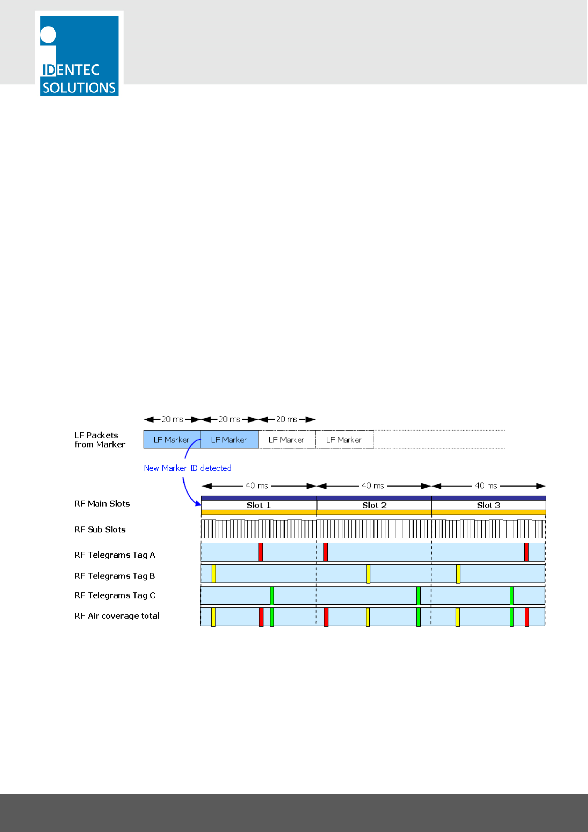
4.8. Information on Burst Settings for the Marker
The parameter “Time between Bursts (Marker)” is not simply a delay time. It is in fact a timeslot. In
this timeslot, the Transponder chooses a random moment to do a single burst. This avoids that burst
collisions with other Transponders, that are simultaneously triggered by the same marker loop. These
timeslots are repeated until all bursts are sent.
In the event that dozens of Transponders are triggered to burst at once, this value can be increased.
The result of increasing the slot width is there will be a longer time interval between other bursts
being sent. For example, with an increased value of 700 ms and 8 bursts, the amount of time for all
bursts is 5.6 seconds.
Example
This example shows 3 Transponders (A, B, C) that are simultaneously triggered by a marker loop (LF
marker) and are configured to burst 3 times. The timeslot (Time between Bursts) is set to the default
value of 40 ms.
The last row shows how the random use of the timeslot avoids collision between the Transponders.
i-Q350-RTLS-AS & i-Q350-RTLS-AH
USER MANUAL
VISIBILITY DELIVERED. PAGE 22 OF 28
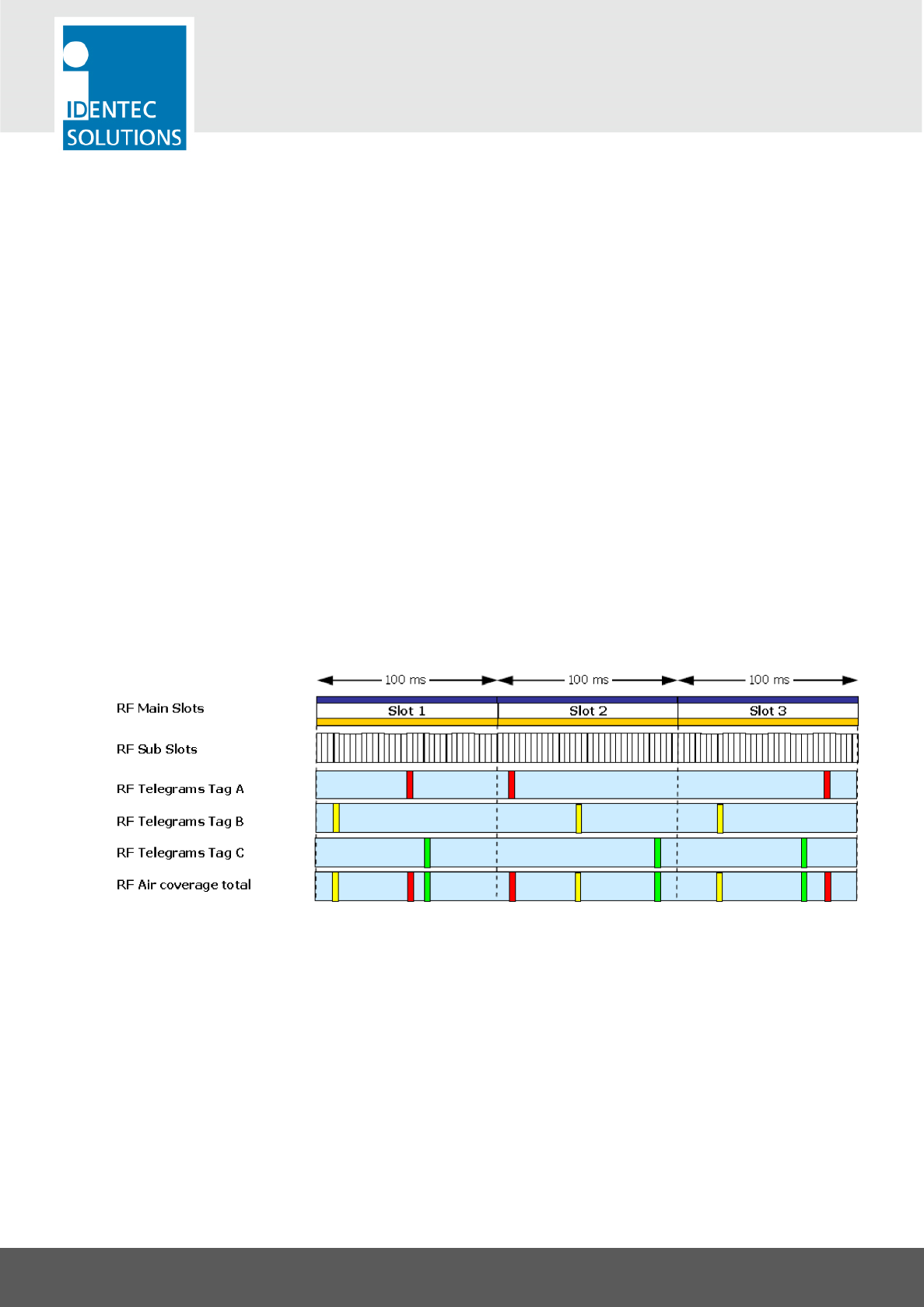
4.9. Information on Burst Settings for the Push Button
The parameter “Time between Bursts (Push Button)” is not simply a delay time. It is in fact a
timeslot. In this timeslot, the Transponder chooses a random moment to do a single burst. This
avoids that burst collisions with other Transponders, that are simultaneously triggered by the same
marker loop. These timeslots are repeated until all bursts are sent.
In the event that dozens of Transponders are triggered to burst at once, this value can be increased.
The result of increasing the slot width is there will be a longer time interval between other bursts
being sent. For example, with an increased value of 700 ms and 8 bursts, the amount of time for all
bursts is 5.6 seconds.
Example
This example shows 3 Transponders (A, B, C) that are simultaneously triggered by a marker loop (LF
marker) and are configured to burst 3 times. The timeslot (Time between Bursts) is set to the default
value of 100 ms.

i-Q350-RTLS-AS & i-Q350-RTLS-AH
USER MANUAL
VISIBILITY DELIVERED. PAGE 23 OF 28
5. TROUBLESHOOTING
5.1. General
This chapter covers how faults can be recognized and rectified. There are potentially four main
problem sources:
• The user control system, including task requirements, communication cables, peripheral units with
possible object recognition switches.
• The SensorSMART platform, including peripheral units and their cables, also potential object
recognition switches.
• The environment, including large objects between antenna and Transponder electrical disturbance
sources, intervention by persons, etc.
• The quality of the technical design, including alignment between antenna, data, ratio of task
requirements/available communication time etc. The information about system performance is
contained in the relevant datasheets.
When planning the total system, do not overlook the problem sources and “Fault finding procedures
on system level” should be included in the host system. How this could look in detail depends on the
relevant system concept and very likely varies from one system to another.

i-Q350-RTLS-AS & i-Q350-RTLS-AH
USER MANUAL
VISIBILITY DELIVERED. PAGE 24 OF 28
6. MAINTENANCE
6.1. General
When installed correctly, the ILR System will operate virtually maintenance free for many years.
However, in the event maintenance is required, only trained and authorized personnel are permitted
to perform the updates, make changes and perform any necessary maintenance.
6.2. Regular cleaning of the Housing Surface
Remove dust with a brush or compressed air. If there are fatty or oily substances, use a soft cloth
moistened with a mild rinsing agent.
Warning
Do not clean the Transponder in a dishwasher. Do not sandblast the Transponder. Do not use a high
pressure water jet or steam cleaner. Do not use cleaning products containing chemical additives.
6.3. Precautionary Maintenance
A regular check of the system is recommended. Unstable connections could lead to damage and
malfunctions of the system and would therefore need to be repaired as soon as possible.
A Brief Checklist
• Are all housings intact?
• Are all cables intact?
• Are all connectors intact?
• Are all connectors securely fastened?
• Are all screws still tight?
• Is there a malfunction in a specific unit?
6.4. Returns
Parts or main components returned for repair or exchange must be handled with great care. All
returns should include an error description and a short application overview and be sent to the local
distributor or to:
IDENTEC SOLUTIONS AG
Service Department
Millenium Park 2
6890 Lustenau
AUSTRIA
i-Q350-RTLS-AS & i-Q350-RTLS-AH
USER MANUAL
VISIBILITY DELIVERED. PAGE 25 OF 28
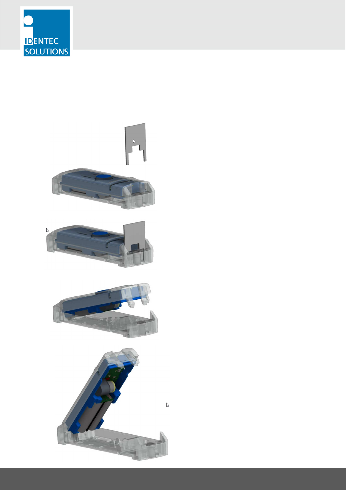
6.5. Battery Exchange
Tools Needed
• RTLS Housing battery compartment removal key
•
Replacement Battery Pack for i-Q350 RTLS (455791)
• WARNING: Batteries only to be replaced by qualified Personnel with correct tools
Open the Housing/Battery Compartment
- Insert tool into designated slots on the
Transponder
- Push down carefully to release the front of the
Transponder housing from the back
- Warning: CAREFULLY take the Transponder in
your hand
Remove The Old Battery Pack
- Pull out the battery gently with fingers
Place new battery pack in
- Place new battery pack in
- Check it is secure and in the correct direction
Close housing

i-Q350-RTLS-AS & i-Q350-RTLS-AH
USER MANUAL
VISIBILITY DELIVERED. PAGE 26 OF 28
7. TECHNICAL DATA
Communication Broadcast 350
Operation Mode Transmits ID and user data in pre-defined interval
Read Range up to 500m*
Compatibility i-PORT M350, i-PORT-USB-BT
Operating Frequency 868 MHz (EU) or 920 MHz (NA) configurable
Transmit Power <1mW (according to national regulations)
Communication Response 350
Operation Mode Bi-directional communication (wake up, read commands &respond)
Read Range up to 250m*
Compatibility i-PORT M350, i-PORT-USB-BT
Operating Frequency 868 MHz (EU) or 920 MHz (NA)
Transmit Power <1mW (according to national regulations)
Communication RTLS
Operation Mode Distance Measurement, bidirectional
Read Range up to 300m*
Compatibility i-PORT M350 RTLS and i-SAT 300 RTLS
Operating Frequency 2.4 GHz
Transmit Power <100 mW (according to national regulations)
Communication Marker
Operation Mode
Receives Marker ID over LF and transmits information over UHF broadcast
Read Range up to 5m (16ft)*
Compatibility i-MARK-SR
Operating Frequency 125 kHz
Data
Data Retention > 10 years without power
Write Cycles 100,000 writes
Memory Size 10,000 Bytes user definable
Identification Code 48 bit fixed ID
Configuration
Device i-PROG M350L or i-PORT M350 or i-Port-USB-BT
Ping Rate Configurable from 0.5 to 300 seconds insteps of 0.5 seconds
Number of Bursts Configurable from 0 to 15
Broadcast User Data Up to 50 Bytes
*The communication range depends on the antenna type, antenna height, the antenna cable runs and the environmental conditions.

i-Q350-RTLS-AS & i-Q350-RTLS-AH
USER MANUAL
VISIBILITY DELIVERED. PAGE 27 OF 28
Electrical
Power Source Battery Pack (replaceable); 2x Lithium cells
Battery Monitoring Yes
Environmental Conditions
Operating Temperature
–20 °C to +85 °C (–4 °F to +185 °F)
Storage Temperature
–20 °C to +85 °C (–4 °F to +185 °F)
Humidity 10% to 95% relative humidity @ 30°C, non-condensing
Shock
EN 60068
-
2
-
32:
Multiple drops to concrete from 1m (3ft),
5
times
EN 60068-2-29: 50G on all 3 axis, 3 times per axis
Vibrations
EN 60068
-
2
-
6: 5G, 20 sin wave cycles per axis, 5
-
500Hz
EN 60068
-
2
-
64: noise 5 to 1000Hz, 90 minutes per axis
Chemical UV resistant for outdoor usage
Standard/Certification
Europe CE (EN 300 220-1, -3; EN 301 489-1,-3; EN 60950)
North America FCC Part 15 (US); Industry Canada
Mechanical Data
Dimensions 138.5 × 43.6 × 28.3 mm (5.45 × 1.72 × 1.11 inches)
Enclosure Material Plastic
Enclosure Rating IP 65
Weight t.b.d
i-Q350-RTLS-AS & i-Q350-RTLS-AH
USER MANUAL
VISIBILITY DELIVERED. PAGE 28 OF 28
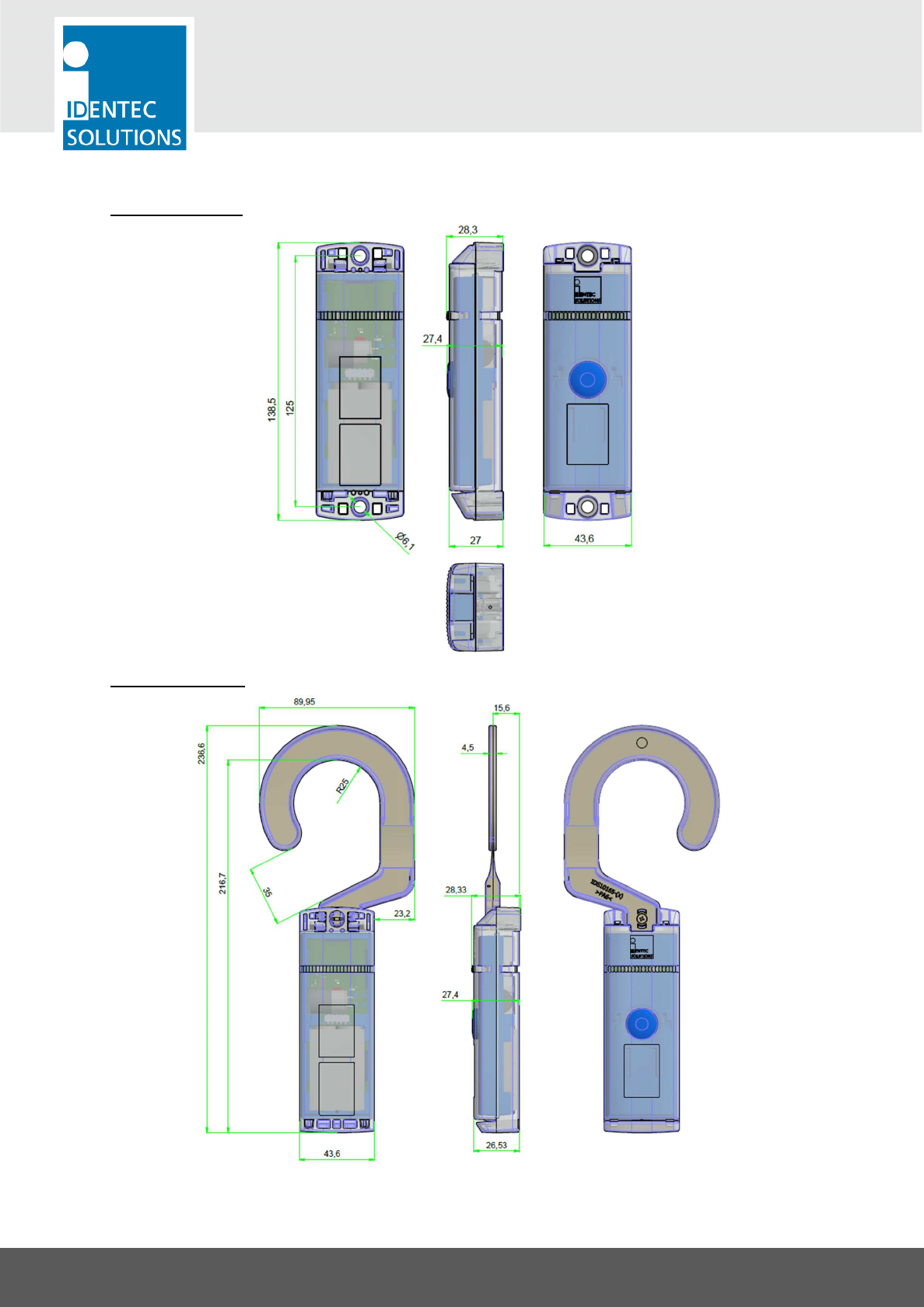
Dimensional Drawing
i-Q350-RTLS-AS:
i-Q350-RTLS-AH: