Identec Solutions IPORT3-NAE Transceiver for ID-System User Manual Proprietary Notice
Identec Solutions AG Transceiver for ID-System Proprietary Notice
UserManual.wiki
>
Identec Solutions
>
IPORT3 NAE User Manual
Users Manual
Navigation menu
Upload a User Manual
Namespaces
Wiki Guide
HTML
PDF
Info
Views
User Manual
Discussion / Help
Navigation


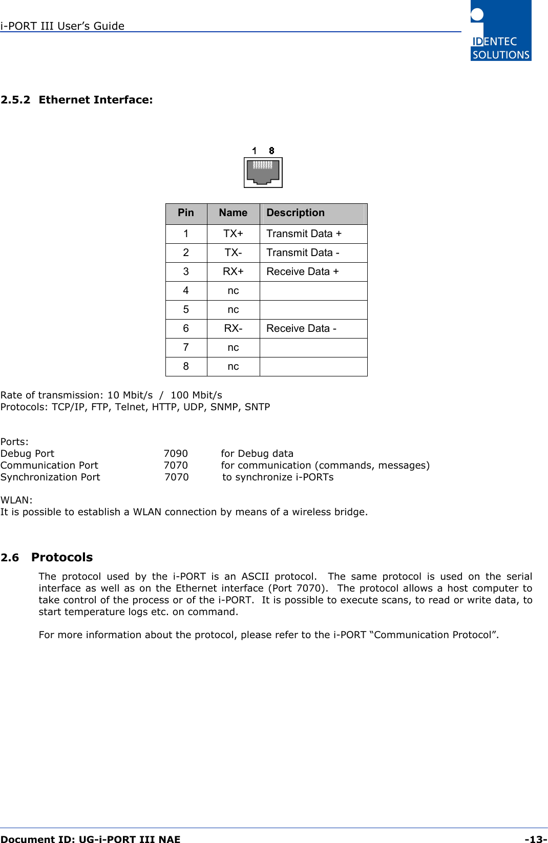
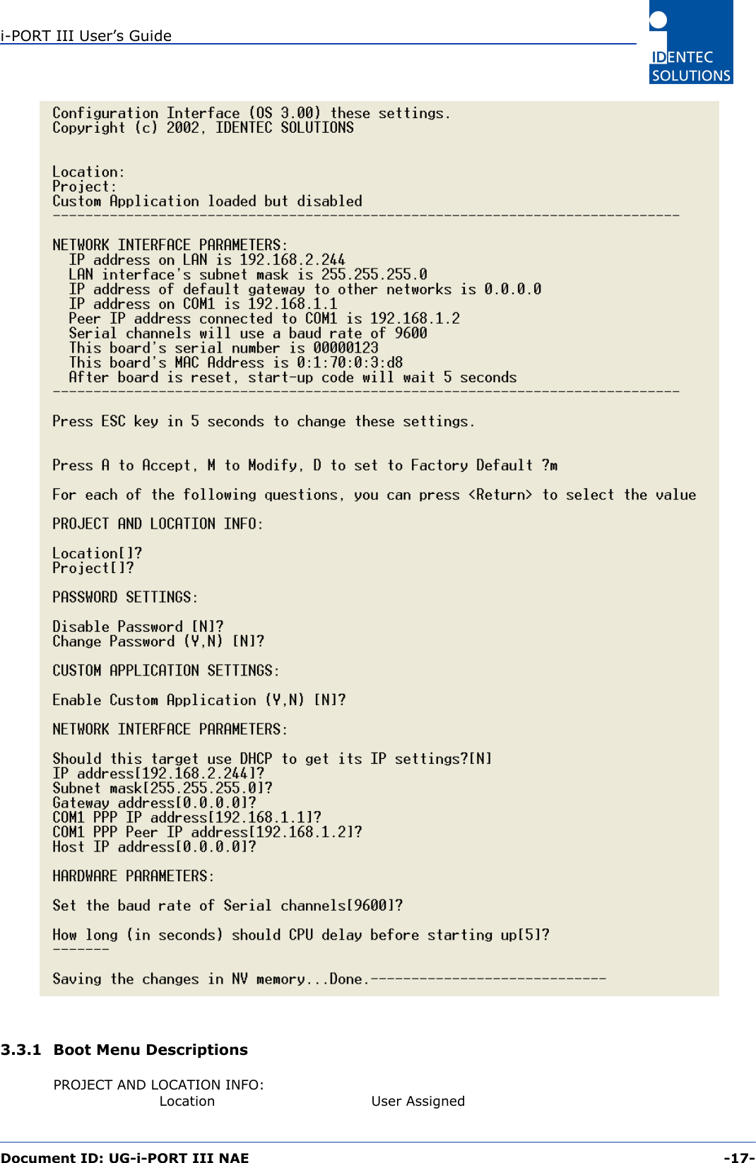
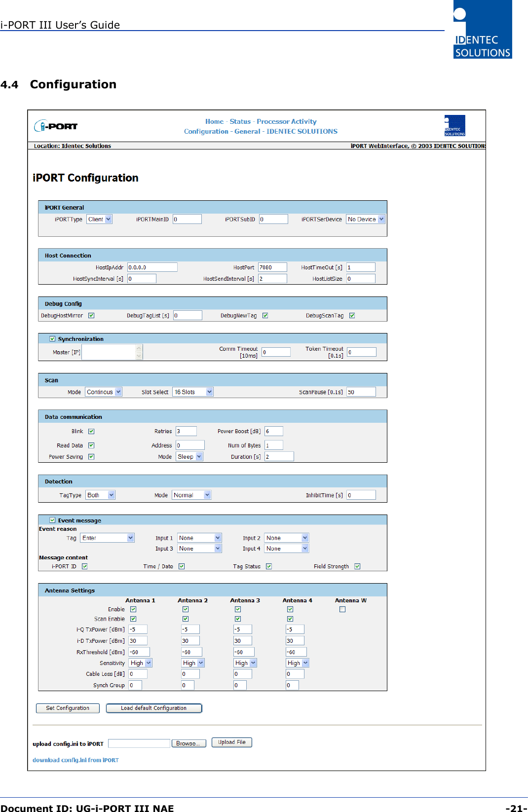
![i-PORT III User’s Guide Document ID: UG-i-PORT III NAE -8- 2.2 Physical Description 211238,721,918020,5905201a The amount of space required to mount the i-PORT is 200 x 250 x 60 mm (B x H x W). The i-PORT weighs approx. 2 kg. A socket wrench (size 3) is required to open the i-PORT. Use the rubber grommet with hole to feed cables through the housing to the outside (cable diameter 4.75 mm to 6 mm); seal the unused feed-through with the blind plugs. These feed-through are intended for RG58 (antenna), Ethernet or serial cables. For power supply, use the PG fitting [screw joint]. If plugs [jacks, connectors] do not fit through the grommet (i.e. Ethernet), you may cut through the grommet (Note: impermeability!). Enclosure rating IP64 (total protection from water sprayed from all directions) is thus achieved. If greater enclosure rating is required, the i-PORT must be placed in an additional housing.](https://usermanual.wiki/Identec-Solutions/IPORT3-NAE/User-Guide-481279-Page-8.png)