Identec Solutions IQ310CST Active UHF Transponder User Manual
Identec Solutions AG Active UHF Transponder
User Manual
ILR Series i-Q310 Transponders
Models CST/SET/ATR/LPT/DRT/ATN
Installation and Operation Manual

Page 2 of 23
i-Q 310 ISO 18000-7 Transponder Series
Proprietary Notice
This document contains confidential information proprietary to IDENTEC SOLUTIONS and may not be used or
disclosed to other parties in whole or in part without prior written authorization from IDENTEC SOLUTIONS.
Disclaimer and Limitation of Liability
IDENTEC SOLUTIONS AG and its affiliates, subsidiaries, officers, directors, employees and agents provide the
information contained in this Manual on an “as-is” basis and do not make any express or implied warranties or
representations with respect to such information including, without limitation, warranties as to non-infringement,
reliability, fitness for a particular purpose, usefulness, completeness, accuracy or up-to-datedness. IDENTEC
SOLUTIONS shall not in any circumstances be liable to any person for any special, incidental, indirect or
consequential damages, including without limitation, damages resulting from use of or reliance on information
presented herein, or loss of profits or revenues or costs of replacement goods, even if informed in advance of the
possibility of such damages.
Trademarks
“IDENTEC SOLUTIONS”, “Intelligent Long Range”, “ILR” and the stylized “i” are registered trademarks and “i-Q”,
“i-D”, “i-B”, “i-CARD”, “i-PORT”, “i-LINKS”, “Solutions. It’s in our name.”, “Smarten up your assets” are
trademarks of IDENTEC SOLUTIONS, Inc. and/or IDENTEC SOLUTIONS AG.
Copyright Notice
Copyright © 2009 IDENTEC SOLUTIONS. All rights reserved.
No part of this document may be reproduced or transmitted in any form by any means, photographic, electronic,
mechanical or otherwise, or used in any information storage and retrieval system, without the prior written
permission of IDENTEC SOLUTIONS.
Reg. No. IM.0782.EN
Order Code:
Issue 0 / June 2009
– 30. July 2009 –
IDENTEC SOLUTIONS, Inc.
Liberty Plaza II, Suite 375
5057 Keller Springs Rd, Addison, Texas 75001
USA
Tel: (972) 535 4144, Fax: (469) 424-0404, Toll Free: 1 866 402 4211
info@identecsolutions.com
www.identecsolutions.com
Subject to alteration without prior notice.
© Copyright IDENTEC SOLUTIONS 2009
Printed in Germany

Page 3 of 23
i-Q 310 ISO 18000-7 Transponder Series
Radio Frequency Compliance Statement
IDENTEC SOLUTIONS is the responsible party for the compliance of the following devices:
MODELS: i-Q310 CST, i-Q310 SET, i-Q310 ATR, i-Q310 LPT, i-Q310, i-Q310 DRT, i-Q310 ATN
EUROPE: CE
USA FCC, HERO
Canada Industy Canada
USA: FCC ID OO4-IQ310 for Models i-Q310 SET, i-Q310 ATR, i-Q310 LPT, i-Q310 DRT
FCC ID OO4-IQ310CST for Model i-Q310 CST
FCC ID OO4-IQ310ATN for Model i-Q310 ATN
Industry Canada: IC:3538A-IQ310 for Models i-Q310 SET, i-Q310 ATR, i-Q310 LPT, i-Q310 DRT
IC:3538A-IQ310CST for Model i-Q310 CST
IC:3538A-IQ310ATN for Model i-Q310 ATN
HERO:
The user(s) of these products are cautioned to only use accessories and peripherals approved, in advance, by
IDENTEC SOLUTIONS. The use of accessories and peripherals, other than those approved by IDENTEC SOLUTIONS,
or any changes or modifications not expressly approved by the party responsible for compliance could void the user’s
authority to operate the equipment.
European Notification according R&TTE Directive
This equipment complies to Art. 6.4 of R&TTE Directive (1999/5/EC). It is tested for compliance with the following
standards: ETSI EN 300 220, ETSI EN 301 489, EN 60950
USA Notification
This device complies with part 15 of the FCC Rules. Operation is subject to the following two conditions: (1) This
device may not cause harmful interference, and (2) this device must accept any interference received, including
interference that may cause undesired operation.
The user(s) of these products are cautioned to only use accessories and peripherals approved, in advance, by
IDENTEC SOLUTIONS. The use of accessories and peripherals, other than those approved by IDENTEC SOLUTIONS,
or any changes or modifications not expressly approved by the party responsible for compliance could void the user’s
authority to operate the equipment.
The device has been tested and found to comply with the limits for a Class A digital device, pursuant to part 15
of the FCC Rules. These limits are designed to provide reasonable protection against harmful interference when
the equipment is operated in a commercial environment. This equipment generates, uses, and can radiate radio
frequency energy and, if not installed and used in accordance with the instruction manual, may cause harmful
interference to radio communications. Operation of this equipment in a residential area is likely to cause harmful
interference in which case the user will be required to correct the interference at his own expense.

Page 4 of 23
i-Q 310 ISO 18000-7 Transponder Series
Safety Precautions
Important Safety Notes
The system described in this manual is for exclusive operation by trained employees. Only qualified personnel that know the potential
dangers involved should perform the installation, settings, maintenance and repair of the units used.
On account of high operating temperature of 80°C (+176°F) care must be taken, if the tags are heated. To avoid burn wait a while until the
tags have cooled down or use gloves. At temperatures below 0°C (+32°F) tags can be iced. In this case, wait a while until tags are warmed
up or use gloves.
The models i-Q310 SET, i-Q310 CST, i-Q310 ATR, i-Q310 LPT and i-Q310 DRT contain replaceable battery. Due to UL safety clauses this
battery must be replaced only by skilled personnel. See also chapter Battery Replacement Procedure.
All tags contain a battery. That is the reason for the following instructions:
CAUTION
CAUTIONCAUTION
CAUTION
RISK OF EXPLOSION IF BATTERY IS REPLACED
RISK OF EXPLOSION IF BATTERY IS REPLACEDRISK OF EXPLOSION IF BATTERY IS REPLACED
RISK OF EXPLOSION IF BATTERY IS REPLACED
BY AN INCORRECT TYPE.
BY AN INCORRECT TYPE.BY AN INCORRECT TYPE.
BY AN INCORRECT TYPE.
DISPOSE OF USED BATTERIES ACCORDING
DISPOSE OF USED BATTERIES ACCORDINGDISPOSE OF USED BATTERIES ACCORDING
DISPOSE OF USED BATTERIES ACCORDING
TO THE INSTRUCTIONS
TO THE INSTRUCTIONSTO THE INSTRUCTIONS
TO THE INSTRUCTIONS
Operational Safety
The correct and safe use of these systems assumes that operating and service personnel follow the safety measures described in the manual
alongside the generally acceptable safety procedures.
If there is a possibility that safe operation cannot be guaranteed the system must be switched off and secured against accidental use. Then
the service unit responsible must be informed.
Electrostatic Discharge
This product contains components that are sensitive to electrostatic discharges. Please observe the special instructions for
their protection. Incorrect handling can damage the unit and cause the invalidation of the warranty.
Safety Documents
This ILR system was designed, tested and supplied in perfect condition according to document testreport EN60950.
Condensation/Change of Temperature
Moving the systems from a cold to a warm environment could lead to dangerous situations due to condensation. Therefore it must be
ensured that the system can adjust itself to the warmer temperature.
Spare Parts
We recommend that only original products, spare and replacement parts authorized by IDENTEC SOLUTIONS be used for installation, service
and repair. Otherwise IDENTEC SOLUTIONS does not accept any responsibility for materials used, work carried out or possible consequences.

Page 5 of 23
i-Q 310 ISO 18000-7 Transponder Series

Page 6 of 23
i-Q 310 ISO 18000-7 Transponder Series
Contents
1 INTRODUCTION...........................................................................................................7
1.1 I-Q310 SERIES TRANSPONDER FUNCTIONALITY .................................................................. 7
1.2 CST AND SET FEATURES AND BENEFITS ........................................................................... 7
2 TECHNICAL SPECIFICATIONS......................................................................................8
3 TRANSPONDER DESCRIPTION.....................................................................................9
3.1 HOUSING................................................................................................................. 9
3.2 TRANSPONDER DATA MEMORY ..................................................................................... 10
3.3 USB INTERFACE ...................................................................................................... 10
3.4 BATTERY INSTALLATION AND POWER UP INDICATION ........................................................... 11
4 INSTALLATION...........................................................................................................12
4.1 SET MOUNTING OPTIONS........................................................................................... 12
4.2 MOUNTING THE SET TRANSPONDER .............................................................................. 13
4.3 MOUNTING THE CST TRANSPONDER............................................................................... 14
4.4 TRANSPONDER ENCLOSURE PROTECTION.......................................................................... 15
5 INITIAL OPERATION..................................................................................................16
5.1 ACTIVATING THE TRANSPONDER ................................................................................... 16
5.1.1 How to Activate the Transponder............................................................................ 16
5.1.2 Battery Replacement Procedure.............................................................................. 17
5.1.3 CST/SET LED description and operation................................................................... 18
5.1.3.1 Sensor LEDs....................................................................................................................18
5.1.3.2 Light Sensor input ............................................................................................................18
5.1.3.3 Push Button.....................................................................................................................18
5.1.3.4 Humidity Sensor input.......................................................................................................18
5.1.3.5 BAT power LED................................................................................................................19
5.2 CONFIGURATION ...................................................................................................... 19
6 USB OPERATION ........................................................................................................20
6.1 USING THE USB CONNECTION ..................................................................................... 20
6.2 DISCONNECTING THE USB CONNECTION ......................................................................... 20
7 MAINTENANCE AND TROUBLESHOOTING .................................................................21
7.1 TROUBLESHOOTING .................................................................................................. 21
7.2 TRANSPONDER BATTERY............................................................................................. 21
7.2.1 Replacing the Transponder’s Battery....................................................................... 21
7.3 RETURNS............................................................................................................... 22
8 ASSOCIATED DOCUMENTS.........................................................................................23

Page 7 of 23
i-Q 310 ISO 18000-7 Transponder Series
1 Introduction
1.1 i-Q310 Series Transponder Functionality
The i-Q ISO 18000-7 transponders are high performance active RFID devices suitable for a wide
variety of applications. The transponder responds to interrogator commands over the distance of
100 (and more) meters in line of sight. The transponders have a battery with a typical operational
life of 3 or more years. This battery is easily replaceable in most models (ATR, DRT, LPT, SET and
CST) for prolonged life span. The exception is the ATN transponder that has a non-removable
sealed battery.
The i-Q310 series includes the following transponders:
• i-Q310 ATR = Asset Transponder
• i-Q310 ATN = Asset Transponder with Non-Replaceable Battery
• i-Q310 DRT = Data Rich Transponder
• i-Q310 LPT = License Plate Transponder
• i-Q310 SET = Sensor Transponder
• i-Q310 CST = Container Security Transponder
For description and instructions for ATR, ATN, DRT and LPT Transponders, please see a separate i-Q310 Series
Installation and Operation Manual for ATR, ATN, DRT and LPT.
1.2 CST and SET Features and Benefits
100-meters (300 ft) read/write range allows automated identification, tracking and tracing of assets without
human intervention.
The CST and SET transponders offer two memory areas.
o The SET and CST have 128kB of memory allocated for user data
o The SET and CST have 32 bits of memory allocated for a fixed, unique, Identification Code.
o The SET and CST have 32kB of memory allocated for sensor logging.
433 MHz operating frequency allows low-power, long communication range and high data transmission rates
with minimal interference due to local conditions.
ISO / IEC 18000-7 compatible allows manufacturer independent interoperation. US DoD and NATO ITV
compatible.
All transponders carry a speaker for acoustic signalization during search, locate, alarms.
The CST and SET transponders provide USB 2.0 Hardwire Interface for fast and secure data transfer with
USB connection with mini-B connector.
3-year battery lifetime and more delivers long-time maintenance-free operation, without battery
replacement.
CST and SET transponders have a replaceable battery for extended lifetime.
Communication on demand eliminates RF flooding through software-controlled read/write operations.
Non-line-of-sight data transmission allows tags to be buried while transmitting for improved tracking and
tracing efficiency.

i-Q310 ISO 18000-7 Transponder Series
Page 8 of 23
2 Technical Specifications
Performance
Read rate Up to 100 tags/s (Collect Tag Identification Code only)
Max. response time < 150 ms (single tag)
RF Communication
Read range Up to 100 m (300 feet) @ free air
Write range Up to 100 m (300 feet) @ free air
Operating frequency 433.92MHz
Data rate (download to tag) 27.778 Kbits/s
Data rate (upload to reader) 27.778 Kbits/s
Frequency 433.92MHz international ISM band
Modulation FSK ± 50 kHz at 27.778 kHz data rate
Sensitivity -85dBm / range at least 300ft (~100m)
Maximum transmission power 1mW– comply with national regulations
Standard / Certification ISO/IEC 18000-7
Hardwire Communication
Standard USB 2.0
Connector Mini-B
Electrical
Power source Lithium battery (replaceable, except ATN)
Expected battery life Typically 3 years and more depending on usage
Battery monitoring Yes
Data
Data retention >10 years without power
Write cycles 100,000 writes to a tag
Memory size 128k bytes/32k bytes
Identification code 32 bit fixed ID
Environmental
Operating temperature –40°C to +80°C (–40ºF to +176ºF)
Humidity 10% to 90% relative humidity at 30°C (+86ºF)
Shock 50 G, 3 times DIN IEC 68-2-27
Multiple drops to concrete from 1 m (3 ft)
Vibration 3 G, 20 sine wave cycles, 5 Hz to 150 Hz,
DIN IEC 68-2-6
5 G, noise 5 Hz to 1000 Hz, 30 minutes
DIN IEC 68-2-64
Physical
Dimensions (CST) 7 in. length x 4.24 in. width x 3.97 in height.
(17.7 cm x 10.7 cm x 10 cm)
Weight (CST) 200 g (7 oz)
Dimensions (SET) with
bracket 6.25 in. length x 2.15 in. width x 1.75 in. height
(15cm x 5.5 cm x 4.5 cm)
Dimensions (SET) without
bracket 5.76 in length x 2.17 in width x 1.53 in height
(14.6 cm x 5.5 cm x 3.9 cm
Weight (SET) 100 g (3.52 oz)
Enclosure Plastic (ASA / Luran® S)
Enclosure rating IP 65
i-Q310 ISO 18000-7 Transponder Series
Page 9 of 23
3 Transponder Description
3.1 Housing
The SET and CST i-Q310 transponders are made of a rugged plastic housing with IP 65 rating. On the
front side (see Fig. 3.1 and 3.2) there are identification labels, which provide information about the type
of the tag, the tag manufacturer and prime contractor, certifications, barcode and the IAW MIL-Std-129P
markings where appropriate. On the rear side of the transponder, there are brackets with openings for
transponder mounting and for clip-on magnetic mounts. The SET and CST transponders have identical
front panel markings, sensors, and LEDs.
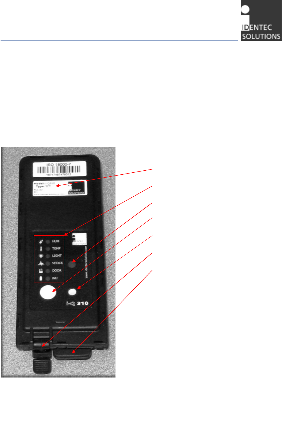
Figure 3.1 Front view of the SET transponder
Product label
Sensor LEDs
Light Sensor input
Push Button
Humidity Sensor input
USB cover
Battery cover
i-Q310 ISO 18000-7 Transponder Series
Page 10 of 23
Figure 3.2 Front view of the CST transponder
3.2 Transponder Data Memory
The CST and SET models of the i-Q310 series transponders offer 128 kBytes of non-volatile memory for
general purpose and user data. In addition, 32kBytes of non-volatile memory is available for sensor
logging.
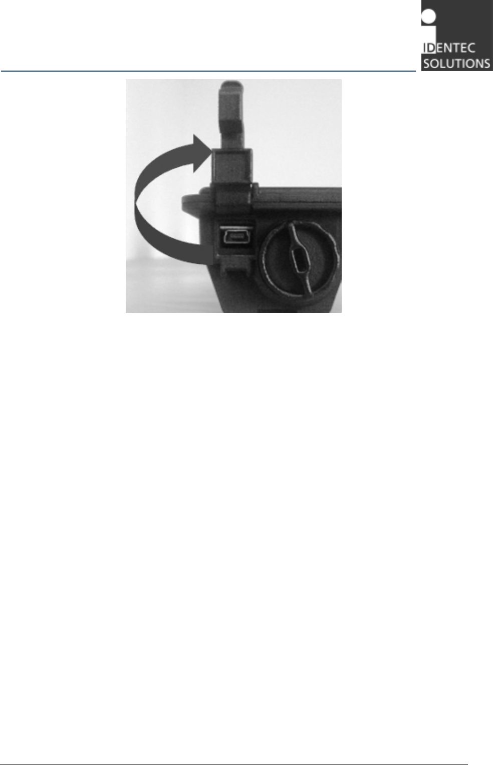
3.3 USB Interface
The transponders are enabled for fast and secure data transfer using USB connection with mini-B
connector. The USB connector is placed next to the battery cap under a separate cover (Fig. 3.3).
i-Q310 ISO 18000-7 Transponder Series
Page 11 of 23
Figure 3.3 USB connector
3.4 Battery installation and power up indication
The transponder ships with the battery reversed; please see Chapter 5 for details on how to power and
activate the transponder.
i-Q310 ISO 18000-7 Transponder Series
Page 12 of 23
4 Installation
4.1 SET Mounting Options
The transponders are designed with two mounting holes so they can be firmly mounted onto virtually
any surface. The transponder can be mounted using various methods dependent on the particular
application. Among the common types of mounting are:
• Screws
• Rivets
• Double sided tape
• Wire ties
• Mounting bracket (Fig. 4.1 and 4.2)
• Magnetic mount (Fig. 4.3)
Figure 4.1 The SET mounting bracket
Figure 4.2 Installing the SET transponder into the bracket
i-Q310 ISO 18000-7 Transponder Series
Page 13 of 23
Figure 4.3 Magnetic mount installation for the SET
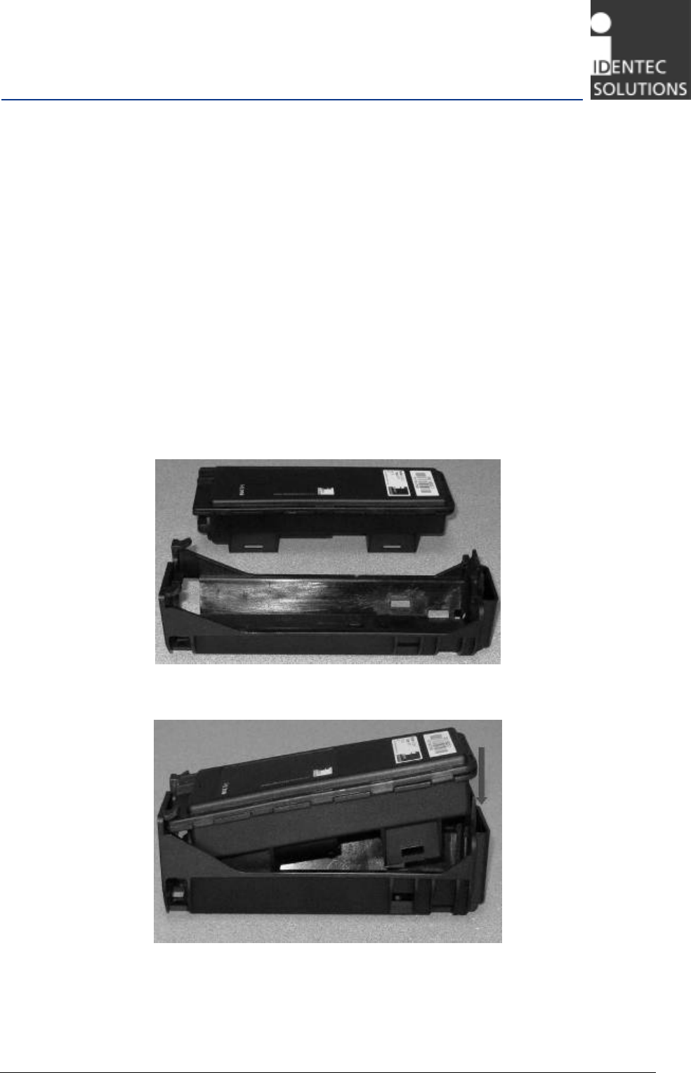
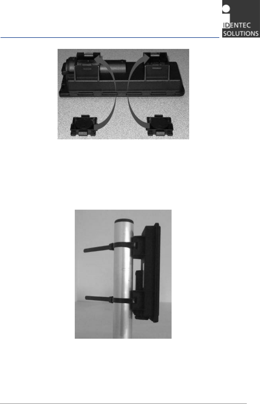
4.2 Mounting the SET Transponder
The transponder has slots that allow mounting using wire ties without the mounting bracket. The
mounting bracket has also openings in order to be wire tied to a post or other object (Fig 2.4).
Figure 4.4 SET Mounting with wire ties
i-Q310 ISO 18000-7 Transponder Series
Page 14 of 23
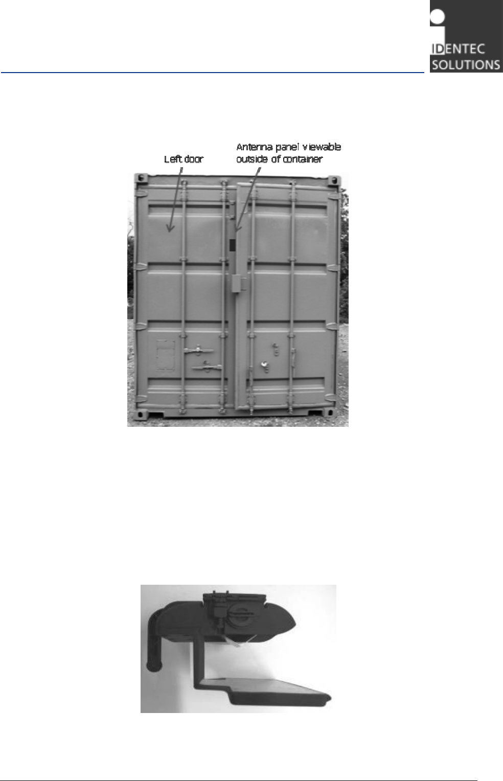
4.3 Mounting the CST transponder
The CST is intended for ISO shipping containers like the one shown below in Fig 4.5.
Figure 4.5 ISO container (typical)
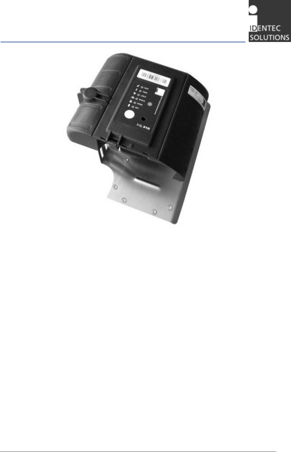
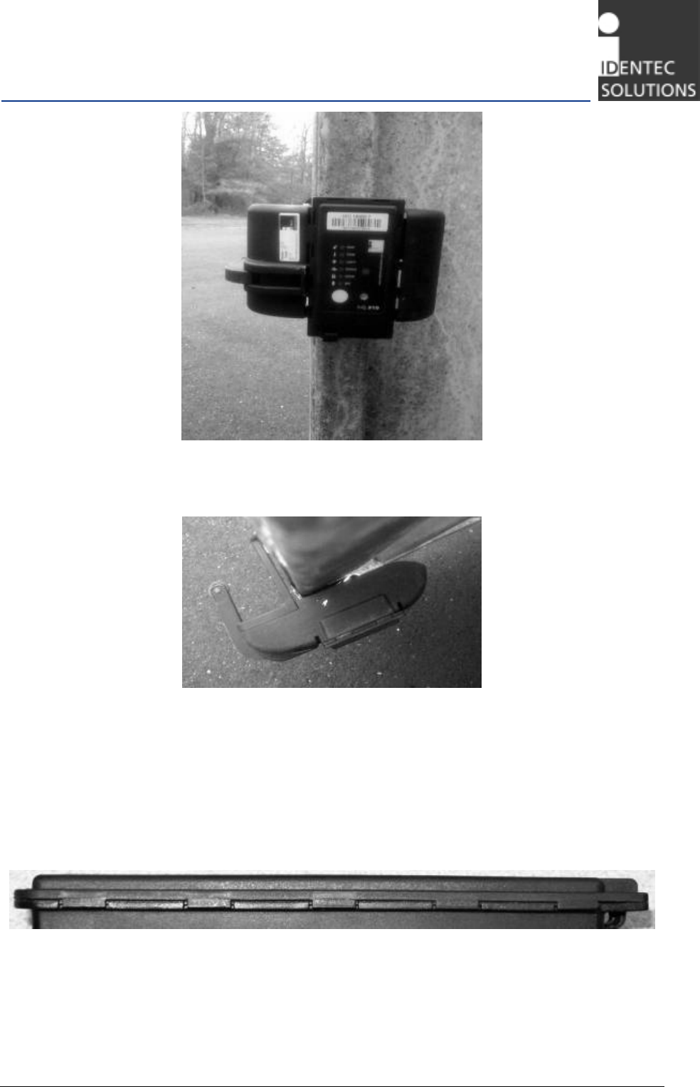
The CST transponder is shown below mounted in various orientations. The ISO door mount opening on
the CST is 55mm (2.17”) shown in Figure 4.6. It must be mounted on the left door with the antenna
outside the container and the sensor body and switch mounted inside the container, shown in Figs 4.8
and 4.9.
The roller switch arm shown in Fig 4.6 and 4.8 should contact the right door to detect a breach or
opening of the door.
Figure 4.6 CST door mount opening
i-Q310 ISO 18000-7 Transponder Series
Page 15 of 23
Figure 4.7 CST inside left door mounting
Figure 4.8 CST inside left door mounting
4.4 Transponder enclosure protection
The CST and SET transponders all have enclosures rated at IP 65. This means that the transponders
are dust tight and water tight. However care should be taken to not immerse in liquids or subject to
powerful jets of water. The transponder casing should not be opened at any time in order to preserve
the integrity of the IP 65 rating and maintain the factory seal.
Figure 4.9 Transponder seal
i-Q310 ISO 18000-7 Transponder Series
Page 16 of 23
5 Initial Operation
5.1 Activating the Transponder
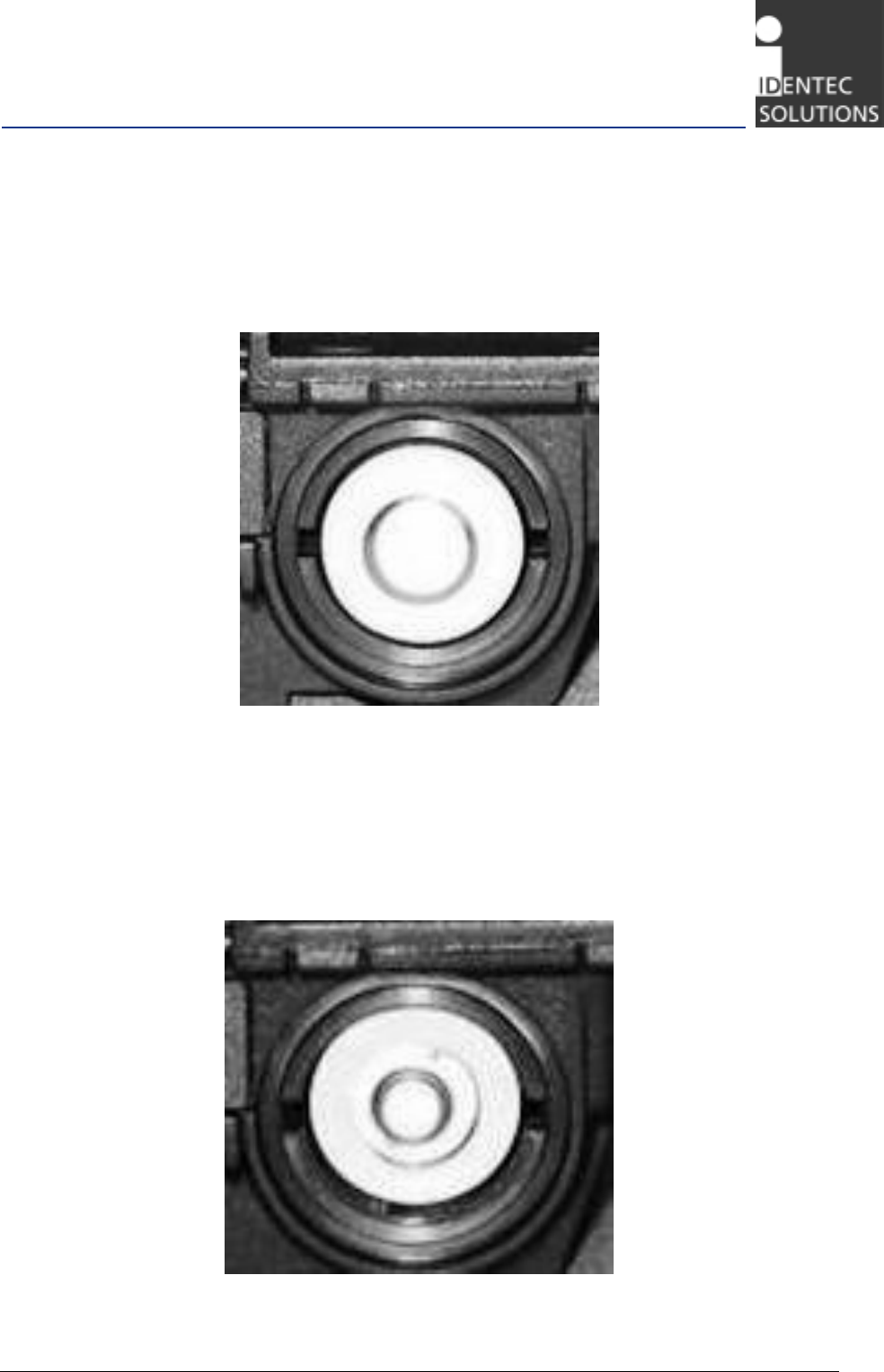
The i-Q310 ISO 18000-7 transponders needs to be activated. They are shipped with a reversed battery
to prevent communication and battery consumption (Fig. 5.1).
Figure 5.1 Battery shown reversed with
the negative (-) terminal shown.
5.1.1 How to Activate the Transponder
Before use, the battery cover has to be opened, battery flipped over and securely closed. This activates
the transponder for operation. Use only A size 3.6 V Lithium Li-SOCl2 batteries.
Figure 5.2 Battery shown in correct orientation with
the positive (+) terminal shown.
i-Q310 ISO 18000-7 Transponder Series
Page 17 of 23
5.1.2 Battery Replacement Procedure
Before starting battery replacement regard following instructions:
1. Due to UL safety clauses this battery must be replaced only by skilled personnel.
2. Warning Fire, explosion and burn hazard
Risk of explosion if battery is replaced by an incorrect type
Do not recharge, short circuit, crush, disassemble, heat above 100°(212°F)
Do not incinerate, or expose contents to water
3. Use only A size 3.6 V Lithium Li-SOCl2 batteries, preferred type: Saft LS 17500
4. Do not replace the battery or open the battery compartment outdoors or in cold or moist
environment. Always replace it in a warm and dry place. If the tag has been brought from a
cold (less than 10 °C/50 °F) into a warm environment it should warm up for 1hour.
5. Do not dispose used batteries into household waste. Used batteries are hazardous waste.
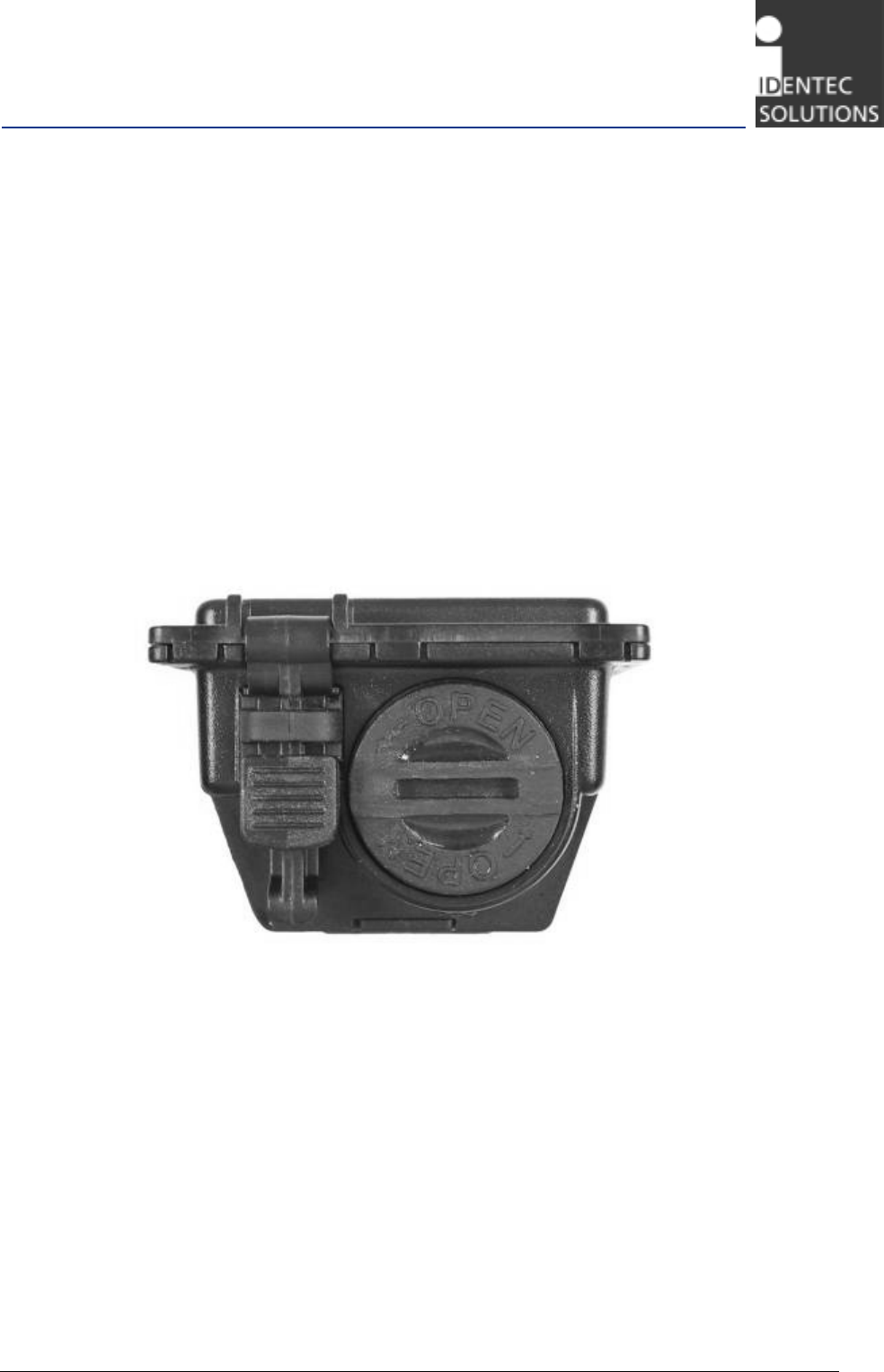
1. Remove the battery cover by rotating counter clockwise while slightly depressing cover (Fig 5.3).
Figure 5.3 Opening the Battery Cap
2. Remove the battery and put it back with the poles reversed (Fig. 5.2). The ⊕ should point out.
3. Replace the battery cover by rotating it clockwise while slightly depressing it.
4. When you hear a short beep, the transponder is activated and ready for operation (see section
5.1.3).
5. If no beep is heard, either the battery is not oriented correctly or it needs to be replaced.
6. Follow steps 2 – 4 for battery replacement in case of depletion.
Note: To keep moisture and dust out of the transponder take care to not lose the o-ring seal on the
battery cover or to leave the battery cover off the transponder for extended periods.
i-Q310 ISO 18000-7 Transponder Series
Page 18 of 23
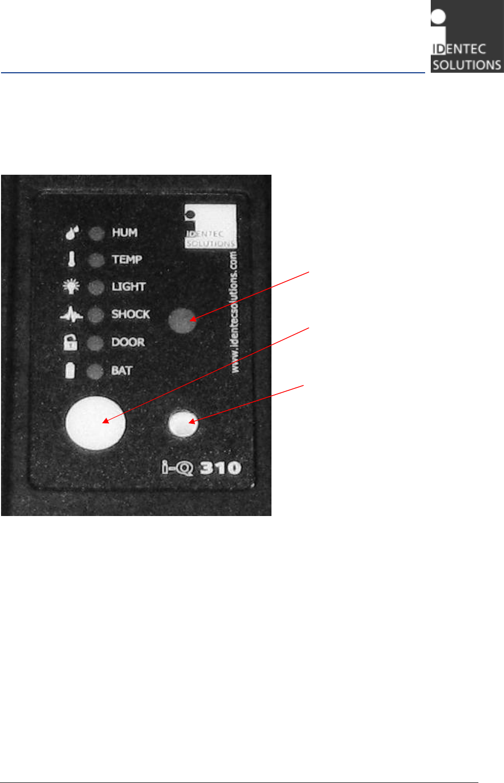
5.1.3 CST/SET LED description and operation
Figure 5.4 LED indicators and sensor inputs
5.1.3.1
Sensor LEDs
The sensor LEDs are illuminated when……….???
5.1.3.2
Light Sensor input
Need description for content
5.1.3.3
Push Button
Need description for content
5.1.3.4
Humidity Sensor input
Need description for content
Light Sensor
Push Button
Humidity Sensor

i-Q310 ISO 18000-7 Transponder Series
Page 19 of 23
5.1.3.5
BAT power LED
The SET and CST transponders have an LED for battery status as indicated in Fig 5.4. If the battery has
more than a 15% charge remaining the LED will be green. Below this level the battery warning flag is
set in memory, and the LED will illuminate red. The battery LED will be off when the battery charge is
depleted or not installed.
5.2 Configuration
The i-Q310 series transponders are not configured directly. They are configured using the i-PORT M-310
device via the air interface and appropriate software. Please see the FDU and Handheld User’s Guide for
information on how to configure transponders.

i-Q310 ISO 18000-7 Transponder Series
Page 20 of 23
6 USB Operation
Important Note
While a transponder is connected via USB to a PC it is continuously powered by the internal battery. In
order to save battery life, please close the USB connection and remove the transponder from the USB
connection after data transfer.
On account of high operating temperature only use usb cable specified up to +80°C (+176°F).
6.1 Using the USB Connection
Please see the FDU Software Manual for details.
6.2 Disconnecting the USB Connection
As the transponder is not operating as a USB mass storage device with buffers that must be flushed
before removal, it is quite easy to disconnect it from the USB connection:
• Stop the service software or cancel the connection to the transponder in the service software.
• Remove the transponder from the USB connection.
• Protect the USB connector by safely tightening the protective rubber lid of the transponder.

i-Q310 ISO 18000-7 Transponder Series
Page 21 of 23
7 Maintenance and Troubleshooting
7.1 Troubleshooting
The transponder does not respond to interrogation at all.
• Make sure the battery is inserted in a correct orientation.
• Make sure the battery is not depleted. Change the battery.
• Tighten the battery cap in order to ensure that both poles are in contact with the transponder’s
circuits.
The transponder is not accessible through USB.
• Ensure that the USB cable is tightly plugged into the transponder and the host PC.
• Switch the USB cable.
• Are the correct drivers installed, communication configured? Please refer to the FDU Software
User’s Manual.
Other issues:
If none of the above steps resolved the issue or there are other issues with the transponder not
mentioned here, please contact technical support.
7.2 Transponder Battery
The battery of the transponder has a typical lifetime expectancy of more than 3 years. A depleted
battery can be replaced with a new one.
7.2.1 Replacing the Transponder’s Battery
For steps on how to replace the battery, please see Chapter 5.
Safety Instructions
Do not replace the battery or open the battery compartment outdoors or in cold or moist environment.
Always replace it in a warm and dry place. If the transponder has been brought from a cold (less than
10 °C/50 °F) into a warm environment it should warm up for 1 hour.
Replace the battery only with a type provided by or recommended by IDENTEC SOLUTIONS.
The battery has to be disposed as special refuse.
Important Note
If the battery is replaced after the transponder has signaled a “battery low” status, simply replace the
battery following the description in advance. The transponder will automatically recognize the battery
exchange and will automatically reset its battery usage counter.
If the battery is replaced on a regular precautionary basis without the “battery low” signal, after
replacing the battery, the transponder needs a service command in order to reset its battery usage
counter.

i-Q310 ISO 18000-7 Transponder Series
Page 22 of 23
7.3 Returns
Parts or main components returned for repair or exchange must be handled with great care. All returns
should include a completed returns form (see appendix) and be sent to:
IDENTEC SOLUTIONS, Inc.
5057 Keller Springs Rd., Ste 375
Addison, TX 75001
USA

i-Q310 ISO 18000-7 Transponder Series
Page 23 of 23
8 Associated Documents
Manuals
IM.0780.EN System Description, English
IM.0781.EN i-PORT F310 Hardware and Installation Manual, English
IM.0782.EN i-Q310 Series Transponder Installation and Operation Manual for ATN, ATR, DRT and
LPT, English
IM.0783.EN i-PORT H310 Handheld Interrogator Module, English
Data Sheets
ID.0680.EN i-PORT F310, English
ID.0681.EN i-Q310 ATN—Asset Transponder, English
ID.0682.EN i-Q310 ATR—Asset Transponder, English
ID.0683.EN i-Q310 DRT—Data Rich Transponder, English
ID.0684.EN i-Q310 SET—Sensor Transponder, English
ID.0685.EN i-Q310 LPT—License Plate Transponder, English
ID.0686.EN i-Q310 CST—Container Security Transponder, English
ID.0689.EN i-PORT H310 Handheld Interrogator Module, English